EP2995796A1 - Uniflow scavenging 2-cycle engine - Google Patents
Uniflow scavenging 2-cycle engine Download PDFInfo
- Publication number
- EP2995796A1 EP2995796A1 EP14795189.1A EP14795189A EP2995796A1 EP 2995796 A1 EP2995796 A1 EP 2995796A1 EP 14795189 A EP14795189 A EP 14795189A EP 2995796 A1 EP2995796 A1 EP 2995796A1
- Authority
- EP
- European Patent Office
- Prior art keywords
- cylinder
- piston
- gas
- port
- scavenge
- Prior art date
- Legal status (The legal status is an assumption and is not a legal conclusion. Google has not performed a legal analysis and makes no representation as to the accuracy of the status listed.)
- Granted
Links
Images


Classifications
-
- F—MECHANICAL ENGINEERING; LIGHTING; HEATING; WEAPONS; BLASTING
- F02—COMBUSTION ENGINES; HOT-GAS OR COMBUSTION-PRODUCT ENGINE PLANTS
- F02B—INTERNAL-COMBUSTION PISTON ENGINES; COMBUSTION ENGINES IN GENERAL
- F02B25/00—Engines characterised by using fresh charge for scavenging cylinders
- F02B25/02—Engines characterised by using fresh charge for scavenging cylinders using unidirectional scavenging
- F02B25/04—Engines having ports both in cylinder head and in cylinder wall near bottom of piston stroke
-
- F—MECHANICAL ENGINEERING; LIGHTING; HEATING; WEAPONS; BLASTING
- F02—COMBUSTION ENGINES; HOT-GAS OR COMBUSTION-PRODUCT ENGINE PLANTS
- F02B—INTERNAL-COMBUSTION PISTON ENGINES; COMBUSTION ENGINES IN GENERAL
- F02B75/00—Other engines
- F02B75/02—Engines characterised by their cycles, e.g. six-stroke
-
- F—MECHANICAL ENGINEERING; LIGHTING; HEATING; WEAPONS; BLASTING
- F02—COMBUSTION ENGINES; HOT-GAS OR COMBUSTION-PRODUCT ENGINE PLANTS
- F02D—CONTROLLING COMBUSTION ENGINES
- F02D19/00—Controlling engines characterised by their use of non-liquid fuels, pluralities of fuels, or non-fuel substances added to the combustible mixtures
- F02D19/06—Controlling engines characterised by their use of non-liquid fuels, pluralities of fuels, or non-fuel substances added to the combustible mixtures peculiar to engines working with pluralities of fuels, e.g. alternatively with light and heavy fuel oil, other than engines indifferent to the fuel consumed
- F02D19/08—Controlling engines characterised by their use of non-liquid fuels, pluralities of fuels, or non-fuel substances added to the combustible mixtures peculiar to engines working with pluralities of fuels, e.g. alternatively with light and heavy fuel oil, other than engines indifferent to the fuel consumed simultaneously using pluralities of fuels
- F02D19/10—Controlling engines characterised by their use of non-liquid fuels, pluralities of fuels, or non-fuel substances added to the combustible mixtures peculiar to engines working with pluralities of fuels, e.g. alternatively with light and heavy fuel oil, other than engines indifferent to the fuel consumed simultaneously using pluralities of fuels peculiar to compression-ignition engines in which the main fuel is gaseous
-
- F—MECHANICAL ENGINEERING; LIGHTING; HEATING; WEAPONS; BLASTING
- F02—COMBUSTION ENGINES; HOT-GAS OR COMBUSTION-PRODUCT ENGINE PLANTS
- F02M—SUPPLYING COMBUSTION ENGINES IN GENERAL WITH COMBUSTIBLE MIXTURES OR CONSTITUENTS THEREOF
- F02M21/00—Apparatus for supplying engines with non-liquid fuels, e.g. gaseous fuels stored in liquid form
- F02M21/02—Apparatus for supplying engines with non-liquid fuels, e.g. gaseous fuels stored in liquid form for gaseous fuels
- F02M21/0218—Details on the gaseous fuel supply system, e.g. tanks, valves, pipes, pumps, rails, injectors or mixers
- F02M21/0248—Injectors
- F02M21/0278—Port fuel injectors for single or multipoint injection into the air intake system
-
- F—MECHANICAL ENGINEERING; LIGHTING; HEATING; WEAPONS; BLASTING
- F02—COMBUSTION ENGINES; HOT-GAS OR COMBUSTION-PRODUCT ENGINE PLANTS
- F02M—SUPPLYING COMBUSTION ENGINES IN GENERAL WITH COMBUSTIBLE MIXTURES OR CONSTITUENTS THEREOF
- F02M21/00—Apparatus for supplying engines with non-liquid fuels, e.g. gaseous fuels stored in liquid form
- F02M21/02—Apparatus for supplying engines with non-liquid fuels, e.g. gaseous fuels stored in liquid form for gaseous fuels
- F02M21/04—Gas-air mixing apparatus
- F02M21/042—Mixer comprising a plurality of bores or flow passages
-
- F—MECHANICAL ENGINEERING; LIGHTING; HEATING; WEAPONS; BLASTING
- F02—COMBUSTION ENGINES; HOT-GAS OR COMBUSTION-PRODUCT ENGINE PLANTS
- F02B—INTERNAL-COMBUSTION PISTON ENGINES; COMBUSTION ENGINES IN GENERAL
- F02B75/00—Other engines
- F02B75/02—Engines characterised by their cycles, e.g. six-stroke
- F02B2075/022—Engines characterised by their cycles, e.g. six-stroke having less than six strokes per cycle
- F02B2075/025—Engines characterised by their cycles, e.g. six-stroke having less than six strokes per cycle two
-
- F—MECHANICAL ENGINEERING; LIGHTING; HEATING; WEAPONS; BLASTING
- F02—COMBUSTION ENGINES; HOT-GAS OR COMBUSTION-PRODUCT ENGINE PLANTS
- F02D—CONTROLLING COMBUSTION ENGINES
- F02D19/00—Controlling engines characterised by their use of non-liquid fuels, pluralities of fuels, or non-fuel substances added to the combustible mixtures
- F02D19/06—Controlling engines characterised by their use of non-liquid fuels, pluralities of fuels, or non-fuel substances added to the combustible mixtures peculiar to engines working with pluralities of fuels, e.g. alternatively with light and heavy fuel oil, other than engines indifferent to the fuel consumed
- F02D19/0639—Controlling engines characterised by their use of non-liquid fuels, pluralities of fuels, or non-fuel substances added to the combustible mixtures peculiar to engines working with pluralities of fuels, e.g. alternatively with light and heavy fuel oil, other than engines indifferent to the fuel consumed characterised by the type of fuels
- F02D19/0642—Controlling engines characterised by their use of non-liquid fuels, pluralities of fuels, or non-fuel substances added to the combustible mixtures peculiar to engines working with pluralities of fuels, e.g. alternatively with light and heavy fuel oil, other than engines indifferent to the fuel consumed characterised by the type of fuels at least one fuel being gaseous, the other fuels being gaseous or liquid at standard conditions
- F02D19/0647—Controlling engines characterised by their use of non-liquid fuels, pluralities of fuels, or non-fuel substances added to the combustible mixtures peculiar to engines working with pluralities of fuels, e.g. alternatively with light and heavy fuel oil, other than engines indifferent to the fuel consumed characterised by the type of fuels at least one fuel being gaseous, the other fuels being gaseous or liquid at standard conditions the gaseous fuel being liquefied petroleum gas [LPG], liquefied natural gas [LNG], compressed natural gas [CNG] or dimethyl ether [DME]
-
- Y—GENERAL TAGGING OF NEW TECHNOLOGICAL DEVELOPMENTS; GENERAL TAGGING OF CROSS-SECTIONAL TECHNOLOGIES SPANNING OVER SEVERAL SECTIONS OF THE IPC; TECHNICAL SUBJECTS COVERED BY FORMER USPC CROSS-REFERENCE ART COLLECTIONS [XRACs] AND DIGESTS
- Y02—TECHNOLOGIES OR APPLICATIONS FOR MITIGATION OR ADAPTATION AGAINST CLIMATE CHANGE
- Y02T—CLIMATE CHANGE MITIGATION TECHNOLOGIES RELATED TO TRANSPORTATION
- Y02T10/00—Road transport of goods or passengers
- Y02T10/10—Internal combustion engine [ICE] based vehicles
- Y02T10/30—Use of alternative fuels, e.g. biofuels
Definitions
- the present invention relates to a uniflow scavenging 2-cycle engine which combusts a premixed gas generated by injecting a fuel gas into an active gas sucked from a scavenge port.
- a scavenge port is provided in an end portion in a stroke direction of a piston of a cylinder, and an exhaust port is provided on the other end portion side in the stroke direction of the piston of the cylinder.
- Patent Document 1 As the communicating hole is provided in the inner wall of the scavenge port, the strength of the inner wall of the scavenge port is decreased. Also, when a plurality of scavenge ports are provided, the thickness of the partition wall between the adjacent scavenge ports becomes thinner to increase the width of the scavenge ports. Therefore, depending on a position where the communicating hole is provided, in addition to a decrease in the strength of the partition wall of the scavenge port, it is difficult to perform even a machining which provides the communicating hole in the partition wall of the scavenge port.
- the present invention has been made in view of such problems, and an object thereof is to provide a uniflow scavenging 2-cycle engine capable of achieving a configuration which injects the fuel gas into an active gas flowing from the scavenge port by a simple machining, without decreasing the strength of the inner wall of the scavenge port.
- a uniflow scavenging 2-cycle engine which includes a cylinder in which a combustion chamber is formed; a piston which slides within the cylinder; a scavenge port which is provided on one end side in a stroke direction of the piston in the cylinder to suck an active gas into the combustion chamber in accordance with the sliding movement of the piston; and a fuel injection unit which has an injection port located on the outside of the cylinder, and injects the fuel gas into the active gas sucked into the scavenge port.
- a plurality of the scavenge ports may be provided to be spaced apart from each other in a circumferential direction of the piston, and the injection port of the fuel injection unit may be located on the radially outer side of the cylinder in a partition wall between the adjacent scavenge ports.
- the fuel injection unit may have a pipe unit into which the fuel gas is introduced, and the pipe unit may be spaced apart from the cylinder on the radially outer side of the cylinder, may surround the cylinder in the circumferential direction, and may be supported independently of the cylinder.
- the fuel injection unit is provided so that its injection port is located on the outside of the cylinder, a configuration which injects the fuel gas into the active gas flowing from the scavenge port can be achieved by a simple machining, without decreasing the strength of the inner wall of the scavenge port.
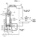
- FIG. 1 is a diagram illustrating an overall configuration of a uniflow scavenging 2-cycle engine 100 in a first embodiment of the present invention.
- the uniflow scavenging 2-cycle engine 100 of this embodiment for example, is used in a vessel or the like.
- the uniflow scavenging 2-cycle engine 100 is configured to include a cylinder 110 (a cylinder head 110a and a cylinder block 110b), a piston 112, a support unit 114, a pilot injection valve 116, an exhaust port 118, an exhaust valve driving device 120, an exhaust valve 122, a scavenge port 124, a scavenge chamber 126, a fuel injection unit 128, a rotary encoder 130 and a combustion chamber 140.
- the uniflow scavenging 2-cycle engine 100 is controlled by a control unit, such as a governor (a speed governor 150), a fuel injection control unit 152 and an exhaust control unit 154.
- the piston 112 connected to a crosshead (not illustrated) slidably reciprocates inside the cylinder 110 through four consecutive strokes, such as intake (air supply), compression, combustion and exhaust.
- intake air supply
- compression combustion
- exhaust exhaust
- a crosshead type piston 112 it is possible to form a relatively long stroke within the cylinder 110, and the crosshead can be subjected to the lateral pressure acting on the piston 112. Accordingly, it is possible to achieve a higher output of the uniflow scavenging 2-cycle engine 100.
- the cylinder 110 is spaced apart from a crank chamber (not illustrated) to which the crosshead is fitted, it is possible to prevent the fouling and deterioration of the crank chamber even when using a low-quality fuel oil.
- the support unit 114 has a base 114a, a locking section 114b and a guide section 114c, and fixedly supports the cylinder 110.
- the base 114a is formed with a cylinder hole 114d into which the cylinder 110 is inserted, and a guide hole 114e into which the guide section 114c is inserted, and supports the overall load of the uniflow scavenging 2-cycle engine 100.
- the locking section 114b is fitted to a groove provided on an outer circumferential surface of the cylinder block 110b of the cylinder 110, and is located above the cylinder hole 114d to lock the cylinder 110 onto the upper surface of the base 114a.
- a rod 112a protruding from the piston 112 in the stroke direction is inserted into the guide section 114c to reduce the radial deviation of the piston 112.
- the pilot injection valve 116 is provided in the cylinder head 110a above the top dead center of the piston 112 which is an end portion in the stroke direction of the cylinder 110 to inject an appropriate amount of fuel at a desired point in the engine cycle.
- fuel oil is naturally ignited by the heat of the combustion chamber 140 surrounded by the cylinder head 110a, a cylinder liner in the cylinder block 110b and the piston 112, and is combusted in a short time to significantly raise the temperature of the combustion chamber 140. Therefore, the premixed gas containing a fuel gas can be reliably combusted at a desired timing.
- the exhaust port 118 is an opening provided on one end side in the stroke direction of the piston 112 in the cylinder 110, that is, on the top of the cylinder head 110a above the top dead center of the piston 112, and is open and closed to exhaust the exhaust gas after combustion occurring in the cylinder 110.
- the exhaust valve driving device 120 causes the exhaust valve 122 to vertically slide at a predetermined timing to open and close the exhaust port 118.
- the exhaust gas exhausted through the exhaust port 118 is supplied to a turbine side of a turbocharger (not illustrated), for example, and is exhausted to the outside.
- the scavenge port 124 is a hole which passes through from an inner circumferential surface (an inner circumferential surface of the cylinder block 110b) of the other end (one end portion) side in the stroke direction of the piston 112 of the cylinder 110 to the outer circumferential surface, and a plurality of scavenge ports 124 are provided over the entire periphery of the cylinder 110 so as to be spaced apart from one another.
- the scavenge port 124 sucks the active gas into the cylinder 110 in accordance with the sliding movement of the piston 112.
- Such an active gas includes oxygen, an oxidizing agent such as ozone or a mixed gas (e.g., air).
- the scavenge chamber 126 is filled with an inert gas (e.g., air) pressed by a compressor of a turbocharger (not illustrated), and the active gas is sucked from the scavenge port 124 under a differential pressure between the scavenge chamber 126 and the cylinder 110.
- a pressure gauge may be provided in the scavenge port 124 to control other parameters, such as an injection amount of the fuel gas, depending on the measured value.
- FIGS. 2A to 2D are diagrams for describing a fuel injection unit 128, FIG. 2A illustrates a part of the cylinder 110 and the fuel injection unit 128 in the same cross-section as in FIG. 1 , FIG. 2B illustrates a cross-section taken along the line II (b)-II (b) in FIG. 2A , and FIG. 2C illustrates a view taken along an arrow II (c) in FIG. 2B . Further, FIG. 2D illustrates an enlarged view of a broken line part of FIG. 2C . In FIGS. 2A to 2D , in order to facilitate understanding, the cross-sectional structure of the fuel injection unit 128 and the piston 112 are not illustrated.
- the fuel injection unit 128 has mixing tubes 128a and 128b which are formed separately from the cylinder 110.
- Each of the mixing tubes 128a and 128b is an annular member which surrounds a radially outer side of the cylinder 110 in the circumferential direction.
- the mixing tube 128a is disposed further on the one end side (an upper side in FIG. 2A ) in the stroke direction of the piston 112 than the scavenge port 124
- the mixing tube 128b is disposed further on the other end side (a lower side of FIG. 2A ) in the stroke direction of the piston 112 than the scavenge port 124.
- a ring 156a is fitted to a groove 110c formed on the upper side of the mixing tube 128a, thereby restricting the upward movement of the mixing tube 128a by the ring 156a.
- a ring 156b is fitted to a groove 110d formed on the lower side of the mixing tube 128b, thereby restricting the downward movement of the mixing tube 128b by the ring 156b.
- the mixing tube 128b includes two members 158a and 158b which surround the cylinder 110 by half the circumference in the circumferential direction, and protrusions 158c and 158d provided at the respective both end portions of the members 158a and 158b are fastened by a chain and a nut (a so-called G-coupling). That is, the mixing tube 128b tightens the cylinder 110 from the outer circumferential side, and the vertical movement of the mixing tube 128b in FIG. 2A is also limited by the frictional force of a contact portion between the mixing tube 128b and the cylinder 110.
- the fixing means of the mixing tube 128b has been described, the mixing tube 128a is also fastened by the same structure as the mixing tube 128b.
- a mixing chamber which annularly extends is formed on the inside of each of the mixing tubes 128a and 128b.
- Each mixing chamber communicates with a fuel pipe (not illustrated) through which the fuel gas obtained by gasifying a liquefied natural gas (LNG) flows, and an active pipe (not illustrated) through which the active gas flows through a switching valve 128c.
- LNG liquefied natural gas
- the fuel gas from the fuel pipe is mixed with the active gas from the active pipe in the mixing chamber to generate a premixed gas.
- the fuel gas it is possible to apply, for example, a gas obtained by gasifying a liquefied petroleum gas (LPG), light oil and heavy oil, without being limited to the LNG.
- LPG liquefied petroleum gas
- a circulation tube 128d is provided between the mixing tube 128a and the mixing tube 128b, and both ends are fixed to each of the mixing tube 128a and the mixing tube 128b.
- the circulation tube 128d is disposed for each partition wall 124a one by one, at a position (the radially outer side of the partition wall 124a of the scavenge port 124) which faces the partition wall 124a provided between the adjacent scavenge ports 124, of the outer circumferential surface of the cylinder 110.
- the circulation tube 128d includes a circulation tube communicating with the mixing tube 128a, and a circulation tube communicating with the mixing tube 128b, and these are alternately disposed in the circumferential direction of the cylinder 110. That is, one of the adjacent circulation tubes 128d communicates with the mixing tube 128a, and the other thereof communicates with the mixing tube 128b. Moreover, the premixed gas containing the fuel gas flowing from the mixing tube 128a or the mixing tube 128b flows through the circulation tube 128d.
- an injection port 128e is formed in the circulation tube 128d.
- the injection port 128e is a hole through which the inner circumferential surface and the outer circumferential surface of the circulation tube 128d communicate with each other. That is, the injection port 128e is located on the radially outer side (the outer side of the cylinder 110) between the adjacent scavenge ports 124. In addition, the injection port 128e is open in a direction toward the circumferential direction of the cylinder 110 from the circulation tube 128d.
- the switching valve 128c when the switching valve 128c is open by receiving a command from a fuel injection control unit 152 to be described below, the premixed gas is ejected from the injection port 128e which is only open. Then, the premixed gas is sprayed from the injection port 128e of the fuel injection unit 128 toward the active gas, which flows from the scavenge chamber 126 toward the scavenge port 124. At this time, a vortex is generated in the active gas near the scavenge port 124, and it is possible to promote mixing between the active gas and the premixed gas by the vortex.
- the fuel injection control unit 152 is provided on the radially outer side of the cylinder 110 separately from the cylinder 110. Therefore, it is possible to form the fuel injection unit 128 by a simple machining, without decreasing the strength of the partition wall 124a of the scavenge ports 124, and without requiring a high difficulty of machining the partition wall 124a of the scavenge port 124.
- the circulation tube 128d formed with the injection port 128e is located on the radially outer side of the cylinder 110 between the adjacent scavenge ports 124. Therefore, it is possible to avoid a situation in which the circulation tube 128d disturbs the flow of the active gas circulating through the scavenge port 124.
- the rotary encoder 130 is provided on a crank mechanism (not illustrated) to detect an angle signal (hereinafter, referred to as a crank angle signal) of the crank.
- the governor 150 derives an amount of fuel injection, based on the engine output command value input from the upper controller, and the engine rotational speed obtained by the crank angle signal from the rotary encoder 130, and outputs the derived amount of fuel injection to the fuel injection control unit 152.
- the fuel injection control unit 152 controls the switching valve 128c (see FIG. 2A ), based on information that indicates the derived amount of fuel injection input from the governor 150, and the crank angle signal from the rotary encoder 130.
- the exhaust control unit 154 outputs an exhaust valve operating signal to the exhaust valve driving device 120, based on a signal relating to the amount of fuel injection from the fuel injection control unit 152, and the crank angle signal from the rotary encoder 130.
- FIG. 3 is a diagram illustrating the operation of each control unit. As illustrated in FIG. 3 , in the exhaust stroke after the combustion stroke, the exhaust port 118 and the scavenge port 124 are in the closed state, and the exhaust gas fills the combustion chamber 140 (within the cylinder 110).
- the exhaust control unit 154 opens the exhaust valve 122 through the exhaust valve driving device 120, and the scavenge port 124 is open in accordance with the sliding operation of the piston 112 (t1 illustrated in FIG. 3 ). Then, the active gas is sucked from the scavenge port 124.
- the fuel injection control unit 152 opens the switching valve 128c, based on the information indicating the derived amount of fuel injection input from the governor 150, and the engine rotational speed derived by the crank angle signal from the rotary encoder 130, thereby injecting the premixed gas to the radially outer side of the cylinder 110 of the scavenge port 124 from the fuel injection unit 128.
- the premixed gas is included in the active gas before being sucked into the scavenge port 124.
- the premixed gas rises, while forming a swirl for promoting the mixing between the active gas and the fuel gas included in the premixed gas, and pushes out the exhaust gas of the combustion chamber 140 (within the cylinder 110) from the exhaust port 118.
- the fuel injection control unit 152 closes the switching valve 128c, and the injection of the fuel gas into the scavenge port 124 from the fuel injection unit 128 is stopped. Further, the scavenge port 124 is closed, and the suction of the active gas is stopped.
- the exhaust control unit 154 maintains the exhaust valve 122 in the open state, and subsequently, the exhaust gas of the combustion chamber 140 (within the cylinder 110) is discharged from the exhaust port 118 by the ascent of the piston 112.
- the exhaust control unit 154 closes the exhaust valve 122 to close the exhaust port 118 (t2 illustrated in FIG. 3 ). Moreover, an explosion is generated by the combustion action of the combustion chamber 140.
- FIG. 4 is an explanatory diagram for describing a uniflow scavenging 2-cycle engine 200 of the second embodiment.
- FIG. 4 of the structure of the uniflow scavenging 2-cycle engine 200, functional units of a control system, configurations above the cylinder block 110b, and the scavenge chamber 126 are not illustrated.
- a mixing tube 228a and a mixing tube (pipe unit) 228b into which the active gas and the fuel gas are introduced surround the cylinder 110 in the circumferential direction, in a state of being spaced apart from the cylinder 110 on the radially outer side of the cylinder 110, without coming into contact with the cylinder 110.
- a base 202 and a support rod 204 are disposed to support the fuel injection unit 228.
- the base 202 is an annular member fixed to the base 114a on one end side in the stroke direction of the cylinder 110, and has an outer diameter larger than that of the cylinder 110, and the rod 112a of the piston 112 is inserted into the base 202. Further, a step is formed on a lower surface 202b of the base 202 to fit the base 114a, and an upper surface 202a of the base 202 is substantially horizontally maintained.
- the support rod 204 is a rod-like member which is fixed to the upper surface 202a of the base 202, its one end is fixed to the base 202 and the other end supports the mixing tube 228b.
- a circulation tube 228d of the fuel injection unit 228 is fixed to the mixing tube 228a at one end and is fixed to the mixing tube 228b at the other end.
- the fuel injection unit 228 is fixedly supported by the base 202 via a support rod 204 and does not come into contact with the cylinder 110.
- the cylinder 110 is supported by the support unit 114, and when releasing the support of the support unit 114, it is possible to pull the cylinder 110 upward without detaching the fuel injection unit 228. For this reason, detachment of the cylinder 110 becomes easier during maintenance or the like, and the workability is improved.
- the mixing tubes 128a and 128b are fixed to the cylinder 110 by both the G-coupling structure and the rings 156a and 156b
- the mixing tubes may be fixed to the cylinder 110 by one of the G-coupling structure and the rings 156a and 156b.
- the fuel injection units 128 and 228 are configured to include the mixing tubes 128a, 128b, 228a and 228b, the switching valve 128c, the circulation tubes 128d and 228d, and the injection port 128e, any configuration may be adopted as long as the injection port 128e is located on the radially outer side of the cylinder 110 to inject the fuel gas to the active gas which is sucked into the scavenge port 124.
- the injection port 128e may be located in front of the scavenge port 124 and may be located to be shifted to one end side or the other end side in the stroke direction of the piston 112 from the scavenge port 124.
- a configuration may be adopted in which only the fuel gas is injected from the fuel injection unit 128 to generate the premixed gas by being mixed with the active gas in the cylinder 110.
- the present invention can be utilized in a uniflow scavenging 2-cycle engine which combusts the premixed gas generated by injecting the fuel gas into the active gas sucked from the scavenge port.
Landscapes
- Engineering & Computer Science (AREA)
- Chemical & Material Sciences (AREA)
- Combustion & Propulsion (AREA)
- Mechanical Engineering (AREA)
- General Engineering & Computer Science (AREA)
- Oil, Petroleum & Natural Gas (AREA)
- Chemical Kinetics & Catalysis (AREA)
- General Chemical & Material Sciences (AREA)
- Fuel-Injection Apparatus (AREA)
- Combustion Methods Of Internal-Combustion Engines (AREA)
- Cylinder Crankcases Of Internal Combustion Engines (AREA)
Abstract
Description
- The present invention relates to a uniflow scavenging 2-cycle engine which combusts a premixed gas generated by injecting a fuel gas into an active gas sucked from a scavenge port.
- Priority is claimed on Japanese Patent Application No.
2013-100529, filed on May 10, 2013 - In a uniflow scavenging 2-cycle engine (a 2-stroke engine) which is also used as an engine of a vessel, a scavenge port is provided in an end portion in a stroke direction of a piston of a cylinder, and an exhaust port is provided on the other end portion side in the stroke direction of the piston of the cylinder. When an active gas is sucked into a combustion chamber from the scavenge port in an intake (air supply) stroke, the exhaust gases generated by the combustion operation are exhausted by being pushed out of the exhaust port by the sucked active gas. At this time, a premixed gas is generated by injecting the fuel gas into the sucked active gas, the combustion operation is performed by compressing the generated premixed gas, and the piston reciprocates within the cylinder by the explosive pressure generated by the combustion operation.
- In such a uniflow scavenging 2-cycle engine, when the mixing between the fuel gas and the active gas is insufficient, the concentration of the fuel gas locally increases, and there are problems such as pre-ignition and emission of an unburned gas. Therefore, for example, as disclosed in Patent Document 1, a communicating hole is provided in an inner wall of the scavenge port, and a nozzle tube protrudes into the scavenge port from the communicating hole. Moreover, there is disclosed a technique for securing the mixing time of the fuel gas and the active gas within the cylinder, by injecting the fuel gas into the scavenge port from the nozzle tube, and by starting the mixing between the active gas and the fuel gas before the active gas is sucked into the cylinder.
- Japanese Patent No.
3908855 - However, in the configuration of Patent Document 1, as the communicating hole is provided in the inner wall of the scavenge port, the strength of the inner wall of the scavenge port is decreased. Also, when a plurality of scavenge ports are provided, the thickness of the partition wall between the adjacent scavenge ports becomes thinner to increase the width of the scavenge ports. Therefore, depending on a position where the communicating hole is provided, in addition to a decrease in the strength of the partition wall of the scavenge port, it is difficult to perform even a machining which provides the communicating hole in the partition wall of the scavenge port.
- The present invention has been made in view of such problems, and an object thereof is to provide a uniflow scavenging 2-cycle engine capable of achieving a configuration which injects the fuel gas into an active gas flowing from the scavenge port by a simple machining, without decreasing the strength of the inner wall of the scavenge port.
- In order to solve the above-mentioned problems, according to a first aspect of the present invention, there is provided a uniflow scavenging 2-cycle engine which includes a cylinder in which a combustion chamber is formed; a piston which slides within the cylinder; a scavenge port which is provided on one end side in a stroke direction of the piston in the cylinder to suck an active gas into the combustion chamber in accordance with the sliding movement of the piston; and a fuel injection unit which has an injection port located on the outside of the cylinder, and injects the fuel gas into the active gas sucked into the scavenge port.
- In a second aspect, a plurality of the scavenge ports may be provided to be spaced apart from each other in a circumferential direction of the piston, and the injection port of the fuel injection unit may be located on the radially outer side of the cylinder in a partition wall between the adjacent scavenge ports.
- In the first or second aspect, the fuel injection unit may have a pipe unit into which the fuel gas is introduced, and the pipe unit may be spaced apart from the cylinder on the radially outer side of the cylinder, may surround the cylinder in the circumferential direction, and may be supported independently of the cylinder.
- According to the uniflow scavenging 2-cycle engine of the present invention, since the fuel injection unit is provided so that its injection port is located on the outside of the cylinder, a configuration which injects the fuel gas into the active gas flowing from the scavenge port can be achieved by a simple machining, without decreasing the strength of the inner wall of the scavenge port.
-
-
FIG. 1 is an explanatory diagram illustrating an overall configuration of a uniflow scavenging 2-cycle engine in a first embodiment of the present invention. -
FIG. 2A is a cross-sectional view of a part of the cylinder and the fuel injection unit in the same cross-section as inFIG. 1 for illustrating the fuel injection unit. -
FIG. 2B is a cross-sectional view taken along the line II (b) - II (b) ofFIG. 2A . -
FIG. 2C is a view taken along an arrow II (c) ofFIG. 2B . -
FIG. 2D is an enlarged view of a dashed line part ofFIG. 2C . -
FIG. 3 is a diagram illustrating the operation of each control unit in the embodiment. -
FIG. 4 is a diagram for illustrating a uniflow scavenging 2-cycle engine according to a second embodiment of the present invention. - Hereinafter, preferred embodiments of the present invention will be described in detail with reference to the accompanying drawings. Dimensions, materials, and other specific numerical values illustrated in these embodiments are merely examples for facilitating understanding of the present invention, and unless specifically indicated otherwise, the present invention is not limited thereto. In addition, in the present specification and drawings, the elements having substantially the same functions and configurations are denoted by the same reference numerals and the repeated description thereof will not be described. Further, the elements which are not directly related to the present invention will not be illustrated.
-
FIG. 1 is a diagram illustrating an overall configuration of a uniflow scavenging 2-cycle engine 100 in a first embodiment of the present invention. The uniflow scavenging 2-cycle engine 100 of this embodiment, for example, is used in a vessel or the like. Specifically, the uniflow scavenging 2-cycle engine 100 is configured to include a cylinder 110 (acylinder head 110a and acylinder block 110b), apiston 112, asupport unit 114, apilot injection valve 116, anexhaust port 118, an exhaustvalve driving device 120, anexhaust valve 122, ascavenge port 124, ascavenge chamber 126, afuel injection unit 128, arotary encoder 130 and acombustion chamber 140. The uniflow scavenging 2-cycle engine 100 is controlled by a control unit, such as a governor (a speed governor 150), a fuelinjection control unit 152 and anexhaust control unit 154. - In the uniflow scavenging 2-
cycle engine 100, thepiston 112 connected to a crosshead (not illustrated) slidably reciprocates inside thecylinder 110 through four consecutive strokes, such as intake (air supply), compression, combustion and exhaust. In such acrosshead type piston 112, it is possible to form a relatively long stroke within thecylinder 110, and the crosshead can be subjected to the lateral pressure acting on thepiston 112. Accordingly, it is possible to achieve a higher output of the uniflow scavenging 2-cycle engine 100. Further, since thecylinder 110 is spaced apart from a crank chamber (not illustrated) to which the crosshead is fitted, it is possible to prevent the fouling and deterioration of the crank chamber even when using a low-quality fuel oil. - The
support unit 114 has abase 114a, alocking section 114b and aguide section 114c, and fixedly supports thecylinder 110. Thebase 114a is formed with acylinder hole 114d into which thecylinder 110 is inserted, and aguide hole 114e into which theguide section 114c is inserted, and supports the overall load of the uniflow scavenging 2-cycle engine 100. Thelocking section 114b is fitted to a groove provided on an outer circumferential surface of thecylinder block 110b of thecylinder 110, and is located above thecylinder hole 114d to lock thecylinder 110 onto the upper surface of thebase 114a. Arod 112a protruding from thepiston 112 in the stroke direction is inserted into theguide section 114c to reduce the radial deviation of thepiston 112. - The
pilot injection valve 116 is provided in thecylinder head 110a above the top dead center of thepiston 112 which is an end portion in the stroke direction of thecylinder 110 to inject an appropriate amount of fuel at a desired point in the engine cycle. Such fuel oil is naturally ignited by the heat of thecombustion chamber 140 surrounded by thecylinder head 110a, a cylinder liner in thecylinder block 110b and thepiston 112, and is combusted in a short time to significantly raise the temperature of thecombustion chamber 140. Therefore, the premixed gas containing a fuel gas can be reliably combusted at a desired timing. - The
exhaust port 118 is an opening provided on one end side in the stroke direction of thepiston 112 in thecylinder 110, that is, on the top of thecylinder head 110a above the top dead center of thepiston 112, and is open and closed to exhaust the exhaust gas after combustion occurring in thecylinder 110. The exhaustvalve driving device 120 causes theexhaust valve 122 to vertically slide at a predetermined timing to open and close theexhaust port 118. Thus, the exhaust gas exhausted through theexhaust port 118 is supplied to a turbine side of a turbocharger (not illustrated), for example, and is exhausted to the outside. - The
scavenge port 124 is a hole which passes through from an inner circumferential surface (an inner circumferential surface of thecylinder block 110b) of the other end (one end portion) side in the stroke direction of thepiston 112 of thecylinder 110 to the outer circumferential surface, and a plurality ofscavenge ports 124 are provided over the entire periphery of thecylinder 110 so as to be spaced apart from one another. - The
scavenge port 124 sucks the active gas into thecylinder 110 in accordance with the sliding movement of thepiston 112. Such an active gas includes oxygen, an oxidizing agent such as ozone or a mixed gas (e.g., air). Thescavenge chamber 126 is filled with an inert gas (e.g., air) pressed by a compressor of a turbocharger (not illustrated), and the active gas is sucked from thescavenge port 124 under a differential pressure between thescavenge chamber 126 and thecylinder 110. Although the pressure of thescavenge chamber 126 can be substantially constant, when the pressure of thescavenge chamber 126 changes, a pressure gauge may be provided in thescavenge port 124 to control other parameters, such as an injection amount of the fuel gas, depending on the measured value. -
FIGS. 2A to 2D are diagrams for describing afuel injection unit 128,FIG. 2A illustrates a part of thecylinder 110 and thefuel injection unit 128 in the same cross-section as inFIG. 1 ,FIG. 2B illustrates a cross-section taken along the line II (b)-II (b) inFIG. 2A , andFIG. 2C illustrates a view taken along an arrow II (c) inFIG. 2B . Further,FIG. 2D illustrates an enlarged view of a broken line part ofFIG. 2C . InFIGS. 2A to 2D , in order to facilitate understanding, the cross-sectional structure of thefuel injection unit 128 and thepiston 112 are not illustrated. - As illustrated in
FIG. 2A , thefuel injection unit 128 has mixingtubes cylinder 110. Each of themixing tubes cylinder 110 in the circumferential direction. The mixingtube 128a is disposed further on the one end side (an upper side inFIG. 2A ) in the stroke direction of thepiston 112 than thescavenge port 124, and the mixingtube 128b is disposed further on the other end side (a lower side ofFIG. 2A ) in the stroke direction of thepiston 112 than thescavenge port 124. - As illustrated in
FIG. 2A , on the outer circumferential surface of thecylinder 110, aring 156a is fitted to agroove 110c formed on the upper side of the mixingtube 128a, thereby restricting the upward movement of the mixingtube 128a by thering 156a. Similarly, on the outer circumferential surface of thecylinder 110, aring 156b is fitted to agroove 110d formed on the lower side of the mixingtube 128b, thereby restricting the downward movement of the mixingtube 128b by thering 156b. - Further, as illustrated in
FIG. 2B , the mixingtube 128b includes twomembers cylinder 110 by half the circumference in the circumferential direction, andprotrusions members tube 128b tightens thecylinder 110 from the outer circumferential side, and the vertical movement of the mixingtube 128b inFIG. 2A is also limited by the frictional force of a contact portion between the mixingtube 128b and thecylinder 110. Here, although the fixing means of the mixingtube 128b has been described, the mixingtube 128a is also fastened by the same structure as the mixingtube 128b. - A mixing chamber which annularly extends is formed on the inside of each of the
mixing tubes valve 128c. - Moreover, the fuel gas from the fuel pipe is mixed with the active gas from the active pipe in the mixing chamber to generate a premixed gas. Here, as the fuel gas, it is possible to apply, for example, a gas obtained by gasifying a liquefied petroleum gas (LPG), light oil and heavy oil, without being limited to the LNG.
- As illustrated in
FIG. 2C , acirculation tube 128d is provided between the mixingtube 128a and the mixingtube 128b, and both ends are fixed to each of the mixingtube 128a and the mixingtube 128b. As illustrated inFIG. 2D , thecirculation tube 128d is disposed for eachpartition wall 124a one by one, at a position (the radially outer side of thepartition wall 124a of the scavenge port 124) which faces thepartition wall 124a provided between theadjacent scavenge ports 124, of the outer circumferential surface of thecylinder 110. - The
circulation tube 128d includes a circulation tube communicating with the mixingtube 128a, and a circulation tube communicating with the mixingtube 128b, and these are alternately disposed in the circumferential direction of thecylinder 110. That is, one of theadjacent circulation tubes 128d communicates with the mixingtube 128a, and the other thereof communicates with the mixingtube 128b. Moreover, the premixed gas containing the fuel gas flowing from the mixingtube 128a or the mixingtube 128b flows through thecirculation tube 128d. - As illustrated in
FIG. 2D , aninjection port 128e is formed in thecirculation tube 128d. Theinjection port 128e is a hole through which the inner circumferential surface and the outer circumferential surface of thecirculation tube 128d communicate with each other. That is, theinjection port 128e is located on the radially outer side (the outer side of the cylinder 110) between theadjacent scavenge ports 124. In addition, theinjection port 128e is open in a direction toward the circumferential direction of thecylinder 110 from thecirculation tube 128d. - Moreover, when the switching
valve 128c is open by receiving a command from a fuelinjection control unit 152 to be described below, the premixed gas is ejected from theinjection port 128e which is only open. Then, the premixed gas is sprayed from theinjection port 128e of thefuel injection unit 128 toward the active gas, which flows from thescavenge chamber 126 toward thescavenge port 124. At this time, a vortex is generated in the active gas near thescavenge port 124, and it is possible to promote mixing between the active gas and the premixed gas by the vortex. - Further, in this embodiment, the fuel
injection control unit 152 is provided on the radially outer side of thecylinder 110 separately from thecylinder 110. Therefore, it is possible to form thefuel injection unit 128 by a simple machining, without decreasing the strength of thepartition wall 124a of thescavenge ports 124, and without requiring a high difficulty of machining thepartition wall 124a of thescavenge port 124. - In addition, the
circulation tube 128d formed with theinjection port 128e is located on the radially outer side of thecylinder 110 between theadjacent scavenge ports 124. Therefore, it is possible to avoid a situation in which thecirculation tube 128d disturbs the flow of the active gas circulating through thescavenge port 124. - Returning to
FIG. 1 , therotary encoder 130 is provided on a crank mechanism (not illustrated) to detect an angle signal (hereinafter, referred to as a crank angle signal) of the crank. - The
governor 150 derives an amount of fuel injection, based on the engine output command value input from the upper controller, and the engine rotational speed obtained by the crank angle signal from therotary encoder 130, and outputs the derived amount of fuel injection to the fuelinjection control unit 152. - The fuel
injection control unit 152 controls the switchingvalve 128c (seeFIG. 2A ), based on information that indicates the derived amount of fuel injection input from thegovernor 150, and the crank angle signal from therotary encoder 130. - The
exhaust control unit 154 outputs an exhaust valve operating signal to the exhaustvalve driving device 120, based on a signal relating to the amount of fuel injection from the fuelinjection control unit 152, and the crank angle signal from therotary encoder 130. - Hereinafter, the operation of each control unit in the engine cycle of the uniflow scavenging 2-
cycle engine 100 will be described. -
FIG. 3 is a diagram illustrating the operation of each control unit. As illustrated inFIG. 3 , in the exhaust stroke after the combustion stroke, theexhaust port 118 and thescavenge port 124 are in the closed state, and the exhaust gas fills the combustion chamber 140 (within the cylinder 110). - When the
piston 112 moves downward and approaches the bottom dead center, by the explosive pressure generated by the combustion action of thecombustion chamber 140, theexhaust control unit 154 opens theexhaust valve 122 through the exhaustvalve driving device 120, and thescavenge port 124 is open in accordance with the sliding operation of the piston 112 (t1 illustrated inFIG. 3 ). Then, the active gas is sucked from thescavenge port 124. - Moreover, the fuel
injection control unit 152 opens the switchingvalve 128c, based on the information indicating the derived amount of fuel injection input from thegovernor 150, and the engine rotational speed derived by the crank angle signal from therotary encoder 130, thereby injecting the premixed gas to the radially outer side of thecylinder 110 of thescavenge port 124 from thefuel injection unit 128. Thus, the premixed gas is included in the active gas before being sucked into thescavenge port 124. - The premixed gas rises, while forming a swirl for promoting the mixing between the active gas and the fuel gas included in the premixed gas, and pushes out the exhaust gas of the combustion chamber 140 (within the cylinder 110) from the
exhaust port 118. - In the compression stroke in which the
piston 112 rises toward the top dead center from the bottom dead center, the fuelinjection control unit 152 closes the switchingvalve 128c, and the injection of the fuel gas into thescavenge port 124 from thefuel injection unit 128 is stopped. Further, thescavenge port 124 is closed, and the suction of the active gas is stopped. - At this time, the
exhaust control unit 154 maintains theexhaust valve 122 in the open state, and subsequently, the exhaust gas of the combustion chamber 140 (within the cylinder 110) is discharged from theexhaust port 118 by the ascent of thepiston 112. - Thereafter, when the
piston 112 further ascends, theexhaust control unit 154 closes theexhaust valve 122 to close the exhaust port 118 (t2 illustrated inFIG. 3 ). Moreover, an explosion is generated by the combustion action of thecombustion chamber 140. - In this way, by combusting the premixed gas in the
combustion chamber 140, as described above, the exhaust stroke, the intake stroke, the compression stroke and the combustion stroke are repeated. - Hereinafter, a second
fuel injection unit 228 and its support structure in a second embodiment of the present invention will be described. Since the second embodiment is different from the first embodiment only in thefuel injection unit 228 and its support structure, here, the same configuration as the first embodiment will not be described, and only thefuel injection unit 228 and its support structure of the different configuration will be described. -
FIG. 4 is an explanatory diagram for describing a uniflow scavenging 2-cycle engine 200 of the second embodiment. InFIG. 4 , of the structure of the uniflow scavenging 2-cycle engine 200, functional units of a control system, configurations above thecylinder block 110b, and thescavenge chamber 126 are not illustrated. - Although the
fuel injection unit 228 has substantially the same configuration as thefuel injection unit 128 in the first embodiment, a mixingtube 228a and a mixing tube (pipe unit) 228b into which the active gas and the fuel gas are introduced surround thecylinder 110 in the circumferential direction, in a state of being spaced apart from thecylinder 110 on the radially outer side of thecylinder 110, without coming into contact with thecylinder 110. - Moreover, a
base 202 and asupport rod 204 are disposed to support thefuel injection unit 228. Thebase 202 is an annular member fixed to thebase 114a on one end side in the stroke direction of thecylinder 110, and has an outer diameter larger than that of thecylinder 110, and therod 112a of thepiston 112 is inserted into thebase 202. Further, a step is formed on alower surface 202b of the base 202 to fit thebase 114a, and anupper surface 202a of thebase 202 is substantially horizontally maintained. - The
support rod 204 is a rod-like member which is fixed to theupper surface 202a of thebase 202, its one end is fixed to thebase 202 and the other end supports the mixingtube 228b. Acirculation tube 228d of thefuel injection unit 228 is fixed to the mixingtube 228a at one end and is fixed to the mixingtube 228b at the other end. - That is, the
fuel injection unit 228 is fixedly supported by thebase 202 via asupport rod 204 and does not come into contact with thecylinder 110. Thecylinder 110 is supported by thesupport unit 114, and when releasing the support of thesupport unit 114, it is possible to pull thecylinder 110 upward without detaching thefuel injection unit 228. For this reason, detachment of thecylinder 110 becomes easier during maintenance or the like, and the workability is improved. - Although the preferred embodiments of the present invention have been described with reference to the accompanying drawings, the present invention is not limited to such embodiments. It is obvious to those skilled in the art that various changes and modifications are conceivable within the scope described in the claims, and those are understood as naturally belonging to the technical scope of the present invention.
- For example, in the above-described embodiments, although the description has been given of a case where the mixing
tubes cylinder 110 by both the G-coupling structure and therings cylinder 110 by one of the G-coupling structure and therings - Further, in the above-described embodiments, although the description has been given of a case where the
fuel injection units mixing tubes valve 128c, thecirculation tubes injection port 128e, any configuration may be adopted as long as theinjection port 128e is located on the radially outer side of thecylinder 110 to inject the fuel gas to the active gas which is sucked into thescavenge port 124. - Further, in the above-described embodiment, although the description has been given of a case where the
injection port 128e is located on the radially outer side of thecylinder 110 between theadjacent scavenge ports 124, theinjection port 128e may be located in front of thescavenge port 124 and may be located to be shifted to one end side or the other end side in the stroke direction of thepiston 112 from thescavenge port 124. - Further, in the above-described embodiment, the description has been given of a case where the premixed gas of the fuel gas and the active gas is ejected from the
fuel injection unit 128 toward the active gas which flows toward thescavenge ports 124 from thescavenge chamber 126. However, a configuration may be adopted in which only the fuel gas is injected from thefuel injection unit 128 to generate the premixed gas by being mixed with the active gas in thecylinder 110. - The present invention can be utilized in a uniflow scavenging 2-cycle engine which combusts the premixed gas generated by injecting the fuel gas into the active gas sucked from the scavenge port.
-
- 100, 200 Uniflow scavenging 2-cycle engine
- 110 Cylinder
- 112 Piston
- 114 Support unit
- 124 Scavenge port
- 124a Partition wall
- 128, 228 Fuel injection unit
- 128e Injection port
- 202 Base
Claims (3)
- A uniflow scavenging 2-cycle engine comprising:a cylinder in which a combustion chamber is formed;a piston which slides within the cylinder;a scavenge port which is provided on one end side in a stroke direction of the piston in the cylinder to suck an active gas into the combustion chamber in accordance with the sliding movement of the piston; anda fuel injection unit which has an injection port located on the outside of the cylinder, and injects the fuel gas into the active gas sucked into the scavenge port.
- The uniflow scavenging 2-cycle engine of claim 1, wherein a plurality of the scavenge ports are provided to be spaced apart from each other in a circumferential direction of the piston, and
the injection port of the fuel injection unit is located on the radially outer side of the cylinder in a partition wall between the adjacent scavenge ports. - The uniflow scavenging 2-cycle engine of claim 1 or 2, wherein the fuel injection unit has a pipe unit into which the fuel gas is introduced, and
the pipe unit is spaced apart from the cylinder on the radially outer side of the cylinder, surrounds the cylinder in the circumferential direction, and is supported independently of the cylinder.
Applications Claiming Priority (2)
| Application Number | Priority Date | Filing Date | Title |
|---|---|---|---|
| JP2013100529 | 2013-05-10 | ||
| PCT/JP2014/062453 WO2014181861A1 (en) | 2013-05-10 | 2014-05-09 | Uniflow scavenging 2-cycle engine |
Publications (3)
| Publication Number | Publication Date |
|---|---|
| EP2995796A1 true EP2995796A1 (en) | 2016-03-16 |
| EP2995796A4 EP2995796A4 (en) | 2017-01-04 |
| EP2995796B1 EP2995796B1 (en) | 2019-04-24 |
Family
ID=51867333
Family Applications (1)
| Application Number | Title | Priority Date | Filing Date |
|---|---|---|---|
| EP14795189.1A Active EP2995796B1 (en) | 2013-05-10 | 2014-05-09 | Uniflow scavenging 2-cycle engine |
Country Status (7)
| Country | Link |
|---|---|
| US (1) | US9790843B2 (en) |
| EP (1) | EP2995796B1 (en) |
| JP (1) | JP6061026B2 (en) |
| KR (1) | KR101792831B1 (en) |
| CN (1) | CN105209729B (en) |
| DK (1) | DK2995796T3 (en) |
| WO (1) | WO2014181861A1 (en) |
Families Citing this family (2)
| Publication number | Priority date | Publication date | Assignee | Title |
|---|---|---|---|---|
| JP5949183B2 (en) | 2012-06-06 | 2016-07-06 | 株式会社Ihi | 2-stroke uniflow engine |
| JP5983196B2 (en) | 2012-08-31 | 2016-08-31 | 株式会社Ihi | Uniflow scavenging 2-cycle engine |
Family Cites Families (20)
| Publication number | Priority date | Publication date | Assignee | Title |
|---|---|---|---|---|
| JPS5472306A (en) * | 1977-11-18 | 1979-06-09 | Nippon Soken Inc | Two-cycle engine |
| US4682570A (en) * | 1984-11-26 | 1987-07-28 | John Velencei | Internal combustion engine (JV-1) |
| JPH06100094B2 (en) * | 1989-05-09 | 1994-12-12 | いすゞ自動車株式会社 | Control device for two-cycle adiabatic engine |
| DK176118B1 (en) | 1997-04-29 | 2006-09-04 | Man B & W Diesel As | Method of operating a diesel-fueled dual-fuel internal combustion engine and such engine |
| US5870982A (en) * | 1997-11-12 | 1999-02-16 | Strawz; Frank T. | Intake valve of a supercharged two stroke engine |
| US6062178A (en) * | 1998-05-20 | 2000-05-16 | Southwest Research Institute | Method of operating uni-flow two-cycle engine during reduced load conditions |
| JP2002371917A (en) * | 2001-04-13 | 2002-12-26 | Mitsubishi Heavy Ind Ltd | Gas injection device for gas engine |
| US7841322B2 (en) * | 2007-11-16 | 2010-11-30 | Dynamic Fuel Systems, Inc. | Super cooled air and fuel induction system for internal combustion engines |
| JP5811539B2 (en) * | 2011-01-24 | 2015-11-11 | 株式会社Ihi | 2-cycle engine |
| DE102011003909B4 (en) * | 2011-02-10 | 2018-05-30 | Man Diesel & Turbo Se | Two-stroke internal combustion engine and method of operating the same |
| CN103732904B (en) * | 2011-06-14 | 2016-08-24 | Wsc斯利有限公司 | The method of postcritical diesel combustion |
| JP2013234596A (en) * | 2012-05-08 | 2013-11-21 | Mitsubishi Heavy Ind Ltd | Two cycle divided chamber-type gas engine |
| JP5949183B2 (en) | 2012-06-06 | 2016-07-06 | 株式会社Ihi | 2-stroke uniflow engine |
| JP6019941B2 (en) | 2012-08-31 | 2016-11-02 | 株式会社Ihi | Uniflow scavenging 2-cycle engine |
| JP6115045B2 (en) | 2012-08-31 | 2017-04-19 | 株式会社Ihi | Uniflow scavenging 2-cycle engine |
| JP5983196B2 (en) | 2012-08-31 | 2016-08-31 | 株式会社Ihi | Uniflow scavenging 2-cycle engine |
| JP6036128B2 (en) | 2012-10-03 | 2016-11-30 | 株式会社Ihi | Uniflow scavenging 2-cycle engine |
| JP5480961B1 (en) * | 2012-12-14 | 2014-04-23 | 川崎重工業株式会社 | Gas engine drive system and ship |
| WO2014181864A1 (en) | 2013-05-10 | 2014-11-13 | 株式会社Ihi | Uniflow scavenging 2-cycle engine |
| DK2995794T3 (en) | 2013-05-10 | 2018-05-22 | Ihi Corp | LENGTH RINSE TOTAL ENGINE |
-
2014
- 2014-05-09 JP JP2015515905A patent/JP6061026B2/en active Active
- 2014-05-09 WO PCT/JP2014/062453 patent/WO2014181861A1/en not_active Ceased
- 2014-05-09 DK DK14795189.1T patent/DK2995796T3/en active
- 2014-05-09 CN CN201480025812.XA patent/CN105209729B/en active Active
- 2014-05-09 EP EP14795189.1A patent/EP2995796B1/en active Active
- 2014-05-09 KR KR1020157025145A patent/KR101792831B1/en active Active
-
2015
- 2015-11-09 US US14/935,889 patent/US9790843B2/en active Active
Also Published As
| Publication number | Publication date |
|---|---|
| US20160061097A1 (en) | 2016-03-03 |
| KR20150119287A (en) | 2015-10-23 |
| EP2995796A4 (en) | 2017-01-04 |
| KR101792831B1 (en) | 2017-11-01 |
| JP6061026B2 (en) | 2017-01-18 |
| EP2995796B1 (en) | 2019-04-24 |
| JPWO2014181861A1 (en) | 2017-02-23 |
| CN105209729B (en) | 2017-07-28 |
| CN105209729A (en) | 2015-12-30 |
| WO2014181861A1 (en) | 2014-11-13 |
| DK2995796T3 (en) | 2019-06-03 |
| US9790843B2 (en) | 2017-10-17 |
Similar Documents
| Publication | Publication Date | Title |
|---|---|---|
| EP2891780B1 (en) | Uniflow scavenging two-cycle engine | |
| EP2995795B1 (en) | Uniflow scavenging 2-cycle engine | |
| EP2891779B1 (en) | Uniflow scavenging two-cycle engine | |
| EP2905450A1 (en) | Uniflow scavenging 2-cycle engine | |
| JP5998671B2 (en) | 2-cycle engine | |
| US20160061099A1 (en) | Uniflow scavenging 2-cycle engine | |
| EP2995796B1 (en) | Uniflow scavenging 2-cycle engine | |
| JP6003288B2 (en) | Uniflow scavenging 2-cycle engine |
Legal Events
| Date | Code | Title | Description |
|---|---|---|---|
| PUAI | Public reference made under article 153(3) epc to a published international application that has entered the european phase |
Free format text: ORIGINAL CODE: 0009012 |
|
| 17P | Request for examination filed |
Effective date: 20151118 |
|
| AK | Designated contracting states |
Kind code of ref document: A1 Designated state(s): AL AT BE BG CH CY CZ DE DK EE ES FI FR GB GR HR HU IE IS IT LI LT LU LV MC MK MT NL NO PL PT RO RS SE SI SK SM TR |
|
| AX | Request for extension of the european patent |
Extension state: BA ME |
|
| DAX | Request for extension of the european patent (deleted) | ||
| A4 | Supplementary search report drawn up and despatched |
Effective date: 20161205 |
|
| RIC1 | Information provided on ipc code assigned before grant |
Ipc: F02B 25/04 20060101AFI20161129BHEP Ipc: F02B 23/02 20060101ALI20161129BHEP Ipc: F02M 21/02 20060101ALI20161129BHEP |
|
| STAA | Information on the status of an ep patent application or granted ep patent |
Free format text: STATUS: EXAMINATION IS IN PROGRESS |
|
| 17Q | First examination report despatched |
Effective date: 20171012 |
|
| GRAP | Despatch of communication of intention to grant a patent |
Free format text: ORIGINAL CODE: EPIDOSNIGR1 |
|
| STAA | Information on the status of an ep patent application or granted ep patent |
Free format text: STATUS: GRANT OF PATENT IS INTENDED |
|
| INTG | Intention to grant announced |
Effective date: 20181114 |
|
| GRAS | Grant fee paid |
Free format text: ORIGINAL CODE: EPIDOSNIGR3 |
|
| GRAA | (expected) grant |
Free format text: ORIGINAL CODE: 0009210 |
|
| STAA | Information on the status of an ep patent application or granted ep patent |
Free format text: STATUS: THE PATENT HAS BEEN GRANTED |
|
| AK | Designated contracting states |
Kind code of ref document: B1 Designated state(s): AL AT BE BG CH CY CZ DE DK EE ES FI FR GB GR HR HU IE IS IT LI LT LU LV MC MK MT NL NO PL PT RO RS SE SI SK SM TR |
|
| REG | Reference to a national code |
Ref country code: GB Ref legal event code: FG4D |
|
| REG | Reference to a national code |
Ref country code: CH Ref legal event code: EP |
|
| REG | Reference to a national code |
Ref country code: DE Ref legal event code: R096 Ref document number: 602014045428 Country of ref document: DE |
|
| REG | Reference to a national code |
Ref country code: CH Ref legal event code: NV Representative=s name: NOVAGRAAF INTERNATIONAL SA, CH Ref country code: AT Ref legal event code: REF Ref document number: 1124437 Country of ref document: AT Kind code of ref document: T Effective date: 20190515 Ref country code: IE Ref legal event code: FG4D |
|
| REG | Reference to a national code |
Ref country code: DK Ref legal event code: T3 Effective date: 20190529 |
|
| REG | Reference to a national code |
Ref country code: NL Ref legal event code: MP Effective date: 20190424 |
|
| REG | Reference to a national code |
Ref country code: LT Ref legal event code: MG4D |
|
| PG25 | Lapsed in a contracting state [announced via postgrant information from national office to epo] |
Ref country code: NL Free format text: LAPSE BECAUSE OF FAILURE TO SUBMIT A TRANSLATION OF THE DESCRIPTION OR TO PAY THE FEE WITHIN THE PRESCRIBED TIME-LIMIT Effective date: 20190424 |
|
| PG25 | Lapsed in a contracting state [announced via postgrant information from national office to epo] |
Ref country code: NO Free format text: LAPSE BECAUSE OF FAILURE TO SUBMIT A TRANSLATION OF THE DESCRIPTION OR TO PAY THE FEE WITHIN THE PRESCRIBED TIME-LIMIT Effective date: 20190724 Ref country code: FI Free format text: LAPSE BECAUSE OF FAILURE TO SUBMIT A TRANSLATION OF THE DESCRIPTION OR TO PAY THE FEE WITHIN THE PRESCRIBED TIME-LIMIT Effective date: 20190424 Ref country code: PT Free format text: LAPSE BECAUSE OF FAILURE TO SUBMIT A TRANSLATION OF THE DESCRIPTION OR TO PAY THE FEE WITHIN THE PRESCRIBED TIME-LIMIT Effective date: 20190824 Ref country code: AL Free format text: LAPSE BECAUSE OF FAILURE TO SUBMIT A TRANSLATION OF THE DESCRIPTION OR TO PAY THE FEE WITHIN THE PRESCRIBED TIME-LIMIT Effective date: 20190424 Ref country code: HR Free format text: LAPSE BECAUSE OF FAILURE TO SUBMIT A TRANSLATION OF THE DESCRIPTION OR TO PAY THE FEE WITHIN THE PRESCRIBED TIME-LIMIT Effective date: 20190424 Ref country code: SE Free format text: LAPSE BECAUSE OF FAILURE TO SUBMIT A TRANSLATION OF THE DESCRIPTION OR TO PAY THE FEE WITHIN THE PRESCRIBED TIME-LIMIT Effective date: 20190424 Ref country code: LT Free format text: LAPSE BECAUSE OF FAILURE TO SUBMIT A TRANSLATION OF THE DESCRIPTION OR TO PAY THE FEE WITHIN THE PRESCRIBED TIME-LIMIT Effective date: 20190424 Ref country code: ES Free format text: LAPSE BECAUSE OF FAILURE TO SUBMIT A TRANSLATION OF THE DESCRIPTION OR TO PAY THE FEE WITHIN THE PRESCRIBED TIME-LIMIT Effective date: 20190424 |
|
| PG25 | Lapsed in a contracting state [announced via postgrant information from national office to epo] |
Ref country code: GR Free format text: LAPSE BECAUSE OF FAILURE TO SUBMIT A TRANSLATION OF THE DESCRIPTION OR TO PAY THE FEE WITHIN THE PRESCRIBED TIME-LIMIT Effective date: 20190725 Ref country code: BG Free format text: LAPSE BECAUSE OF FAILURE TO SUBMIT A TRANSLATION OF THE DESCRIPTION OR TO PAY THE FEE WITHIN THE PRESCRIBED TIME-LIMIT Effective date: 20190724 Ref country code: RS Free format text: LAPSE BECAUSE OF FAILURE TO SUBMIT A TRANSLATION OF THE DESCRIPTION OR TO PAY THE FEE WITHIN THE PRESCRIBED TIME-LIMIT Effective date: 20190424 Ref country code: PL Free format text: LAPSE BECAUSE OF FAILURE TO SUBMIT A TRANSLATION OF THE DESCRIPTION OR TO PAY THE FEE WITHIN THE PRESCRIBED TIME-LIMIT Effective date: 20190424 Ref country code: LV Free format text: LAPSE BECAUSE OF FAILURE TO SUBMIT A TRANSLATION OF THE DESCRIPTION OR TO PAY THE FEE WITHIN THE PRESCRIBED TIME-LIMIT Effective date: 20190424 |
|
| REG | Reference to a national code |
Ref country code: AT Ref legal event code: MK05 Ref document number: 1124437 Country of ref document: AT Kind code of ref document: T Effective date: 20190424 |
|
| PG25 | Lapsed in a contracting state [announced via postgrant information from national office to epo] |
Ref country code: IS Free format text: LAPSE BECAUSE OF FAILURE TO SUBMIT A TRANSLATION OF THE DESCRIPTION OR TO PAY THE FEE WITHIN THE PRESCRIBED TIME-LIMIT Effective date: 20190824 |
|
| REG | Reference to a national code |
Ref country code: DE Ref legal event code: R097 Ref document number: 602014045428 Country of ref document: DE |
|
| PG25 | Lapsed in a contracting state [announced via postgrant information from national office to epo] |
Ref country code: RO Free format text: LAPSE BECAUSE OF FAILURE TO SUBMIT A TRANSLATION OF THE DESCRIPTION OR TO PAY THE FEE WITHIN THE PRESCRIBED TIME-LIMIT Effective date: 20190424 Ref country code: CZ Free format text: LAPSE BECAUSE OF FAILURE TO SUBMIT A TRANSLATION OF THE DESCRIPTION OR TO PAY THE FEE WITHIN THE PRESCRIBED TIME-LIMIT Effective date: 20190424 Ref country code: AT Free format text: LAPSE BECAUSE OF FAILURE TO SUBMIT A TRANSLATION OF THE DESCRIPTION OR TO PAY THE FEE WITHIN THE PRESCRIBED TIME-LIMIT Effective date: 20190424 Ref country code: EE Free format text: LAPSE BECAUSE OF FAILURE TO SUBMIT A TRANSLATION OF THE DESCRIPTION OR TO PAY THE FEE WITHIN THE PRESCRIBED TIME-LIMIT Effective date: 20190424 Ref country code: MC Free format text: LAPSE BECAUSE OF FAILURE TO SUBMIT A TRANSLATION OF THE DESCRIPTION OR TO PAY THE FEE WITHIN THE PRESCRIBED TIME-LIMIT Effective date: 20190424 Ref country code: SK Free format text: LAPSE BECAUSE OF FAILURE TO SUBMIT A TRANSLATION OF THE DESCRIPTION OR TO PAY THE FEE WITHIN THE PRESCRIBED TIME-LIMIT Effective date: 20190424 |
|
| REG | Reference to a national code |
Ref country code: BE Ref legal event code: MM Effective date: 20190531 |
|
| PG25 | Lapsed in a contracting state [announced via postgrant information from national office to epo] |
Ref country code: IT Free format text: LAPSE BECAUSE OF FAILURE TO SUBMIT A TRANSLATION OF THE DESCRIPTION OR TO PAY THE FEE WITHIN THE PRESCRIBED TIME-LIMIT Effective date: 20190424 Ref country code: LU Free format text: LAPSE BECAUSE OF NON-PAYMENT OF DUE FEES Effective date: 20190509 Ref country code: SM Free format text: LAPSE BECAUSE OF FAILURE TO SUBMIT A TRANSLATION OF THE DESCRIPTION OR TO PAY THE FEE WITHIN THE PRESCRIBED TIME-LIMIT Effective date: 20190424 |
|
| PLBE | No opposition filed within time limit |
Free format text: ORIGINAL CODE: 0009261 |
|
| STAA | Information on the status of an ep patent application or granted ep patent |
Free format text: STATUS: NO OPPOSITION FILED WITHIN TIME LIMIT |
|
| GBPC | Gb: european patent ceased through non-payment of renewal fee |
Effective date: 20190724 |
|
| PG25 | Lapsed in a contracting state [announced via postgrant information from national office to epo] |
Ref country code: TR Free format text: LAPSE BECAUSE OF FAILURE TO SUBMIT A TRANSLATION OF THE DESCRIPTION OR TO PAY THE FEE WITHIN THE PRESCRIBED TIME-LIMIT Effective date: 20190424 |
|
| 26N | No opposition filed |
Effective date: 20200127 |
|
| PG25 | Lapsed in a contracting state [announced via postgrant information from national office to epo] |
Ref country code: IE Free format text: LAPSE BECAUSE OF NON-PAYMENT OF DUE FEES Effective date: 20190509 Ref country code: GB Free format text: LAPSE BECAUSE OF NON-PAYMENT OF DUE FEES Effective date: 20190724 |
|
| PG25 | Lapsed in a contracting state [announced via postgrant information from national office to epo] |
Ref country code: SI Free format text: LAPSE BECAUSE OF FAILURE TO SUBMIT A TRANSLATION OF THE DESCRIPTION OR TO PAY THE FEE WITHIN THE PRESCRIBED TIME-LIMIT Effective date: 20190424 Ref country code: BE Free format text: LAPSE BECAUSE OF NON-PAYMENT OF DUE FEES Effective date: 20190531 |
|
| PG25 | Lapsed in a contracting state [announced via postgrant information from national office to epo] |
Ref country code: FR Free format text: LAPSE BECAUSE OF NON-PAYMENT OF DUE FEES Effective date: 20190624 |
|
| PG25 | Lapsed in a contracting state [announced via postgrant information from national office to epo] |
Ref country code: CY Free format text: LAPSE BECAUSE OF FAILURE TO SUBMIT A TRANSLATION OF THE DESCRIPTION OR TO PAY THE FEE WITHIN THE PRESCRIBED TIME-LIMIT Effective date: 20190424 |
|
| PG25 | Lapsed in a contracting state [announced via postgrant information from national office to epo] |
Ref country code: MT Free format text: LAPSE BECAUSE OF FAILURE TO SUBMIT A TRANSLATION OF THE DESCRIPTION OR TO PAY THE FEE WITHIN THE PRESCRIBED TIME-LIMIT Effective date: 20190424 Ref country code: HU Free format text: LAPSE BECAUSE OF FAILURE TO SUBMIT A TRANSLATION OF THE DESCRIPTION OR TO PAY THE FEE WITHIN THE PRESCRIBED TIME-LIMIT; INVALID AB INITIO Effective date: 20140509 |
|
| PG25 | Lapsed in a contracting state [announced via postgrant information from national office to epo] |
Ref country code: MK Free format text: LAPSE BECAUSE OF FAILURE TO SUBMIT A TRANSLATION OF THE DESCRIPTION OR TO PAY THE FEE WITHIN THE PRESCRIBED TIME-LIMIT Effective date: 20190424 |
|
| REG | Reference to a national code |
Ref country code: DE Ref legal event code: R081 Ref document number: 602014045428 Country of ref document: DE Owner name: MITSUI E&S DU CO., LTD., AIOI-SHI, JP Free format text: FORMER OWNER: IHI CORPORATION, TOKYO, JP |
|
| PGFP | Annual fee paid to national office [announced via postgrant information from national office to epo] |
Ref country code: DE Payment date: 20250402 Year of fee payment: 12 |
|
| PGFP | Annual fee paid to national office [announced via postgrant information from national office to epo] |
Ref country code: DK Payment date: 20250516 Year of fee payment: 12 |
|
| PGFP | Annual fee paid to national office [announced via postgrant information from national office to epo] |
Ref country code: CH Payment date: 20250601 Year of fee payment: 12 |