EP2995551B1 - Lower deck mobile crew rest with lowered floor - Google Patents
Lower deck mobile crew rest with lowered floor Download PDFInfo
- Publication number
- EP2995551B1 EP2995551B1 EP15185372.8A EP15185372A EP2995551B1 EP 2995551 B1 EP2995551 B1 EP 2995551B1 EP 15185372 A EP15185372 A EP 15185372A EP 2995551 B1 EP2995551 B1 EP 2995551B1
- Authority
- EP
- European Patent Office
- Prior art keywords
- floor
- crew rest
- lowerable
- mobile crew
- aircraft
- Prior art date
- Legal status (The legal status is an assumption and is not a legal conclusion. Google has not performed a legal analysis and makes no representation as to the accuracy of the status listed.)
- Not-in-force
Links
Images


Classifications
-
- B—PERFORMING OPERATIONS; TRANSPORTING
- B64—AIRCRAFT; AVIATION; COSMONAUTICS
- B64D—EQUIPMENT FOR FITTING IN OR TO AIRCRAFT; FLIGHT SUITS; PARACHUTES; ARRANGEMENT OR MOUNTING OF POWER PLANTS OR PROPULSION TRANSMISSIONS IN AIRCRAFT
- B64D11/00—Passenger or crew accommodation; Flight-deck installations not otherwise provided for
-
- B—PERFORMING OPERATIONS; TRANSPORTING
- B64—AIRCRAFT; AVIATION; COSMONAUTICS
- B64D—EQUIPMENT FOR FITTING IN OR TO AIRCRAFT; FLIGHT SUITS; PARACHUTES; ARRANGEMENT OR MOUNTING OF POWER PLANTS OR PROPULSION TRANSMISSIONS IN AIRCRAFT
- B64D9/00—Equipment for handling freight; Equipment for facilitating passenger embarkation or the like
-
- B—PERFORMING OPERATIONS; TRANSPORTING
- B64—AIRCRAFT; AVIATION; COSMONAUTICS
- B64D—EQUIPMENT FOR FITTING IN OR TO AIRCRAFT; FLIGHT SUITS; PARACHUTES; ARRANGEMENT OR MOUNTING OF POWER PLANTS OR PROPULSION TRANSMISSIONS IN AIRCRAFT
- B64D11/00—Passenger or crew accommodation; Flight-deck installations not otherwise provided for
- B64D2011/0046—Modular or preassembled units for creating cabin interior structures
-
- B—PERFORMING OPERATIONS; TRANSPORTING
- B64—AIRCRAFT; AVIATION; COSMONAUTICS
- B64D—EQUIPMENT FOR FITTING IN OR TO AIRCRAFT; FLIGHT SUITS; PARACHUTES; ARRANGEMENT OR MOUNTING OF POWER PLANTS OR PROPULSION TRANSMISSIONS IN AIRCRAFT
- B64D11/00—Passenger or crew accommodation; Flight-deck installations not otherwise provided for
- B64D2011/0069—Rest berths, beds or the like
- B64D2011/0076—Rest berths, beds or the like for crew members, e.g. for sleeping during flight
Definitions
- Embodiments of the present disclosure relate generally to lower deck mobile crew rests and improvements to the user experience and use of space therein.
- Crew rests may be used on some aircraft to offer crew members a resting place on long haul flights. Alternatively, passenger seats may be used, although this means that those seats are unavailable for paying customers and also means the crew does not have a comfortable place to sleep.
- lower deck mobile crew rests LDMCRs
- LDMCRs lower deck mobile crew rests
- a LDMCR is generally provided as a container-like space that can be loaded and unloaded onto the aircraft. It is generally desirable that the rest area include space, privacy, and comfort for the users. The rest area may include bunk space, stowage space, lavatory space, and other areas. Improvements to LDMCR containers are desirable in order to improve comfort as well as to improve the loading processes of the LDMCR.
- WO2007/042276 Airbus GMBH; Schuld Michael; Kwik Harry
- the passageway comprises a passageway floor and a displacement device, wherein the displacement device is designed to variably set the height (hi) of the passageway floor.
- Embodiments of the invention described herein thus provide systems and methods for improving lower deck mobile crew rests, the user experience, and the use of space therein.
- a lower floor with a second floor surface that can be extended and retracted from the lower floor.
- a mobile crew rest for an aircraft according to the features of claim 1.
- the lowerable portion may comprise an accordion-like connection to the stationary floor portion of the lower floor.
- the lowerable portion may extend below the stationary floor portion up to about 0.7 meters.
- the lower deck mobile crew rest may have one or more bunk spaces in the interior portion, and the lowerable floor portion may move below the bunk or storage spaces, creating more leg space for users.
- the lowerable floor portion may be vertically raised or lowered via an electrical system, a pneumatic system, a pulley system, manually via a mechanical system, or any combination thereof.
- the lowerable floor portion may be lowered into a space created in a cargo bay area technical floor.
- Embodiments of the present invention provide a crew rest container 10 or space configured to enhance the user experience.
- the crew rest container 10 generally has an upper ceiling 12 and a lower floor 14.
- the floors of crew rest spaces are formed as a traditional, flat floor panel.
- the present disclosure provides a lower floor 14 that can be lowered.
- the present disclosure provides a lower floor 14 with a second floor surface 20 that can be extended and retracted from the lower floor 14.
- this provides a first stationary floor surface formed by the lower floor 14 at a first level "A" and a second floor surface 20 formed by the extendable and retractable second floor surface 20 at a second level "B".
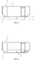
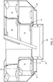
- FIG. 1 When the crew rest container 10 is to be loaded onto an aircraft, the second floor 20 is retracted, as is shown in FIG. 2 . This provides a flat lower surface 22 for the container 10, which can ease the loading and installation process.
- the second floor surface 20 may be extended, as is shown in FIGS. 1 and 5 . This provides a portion of the floor that is lowered further, which may allow a user to stand upright inside the container 10.
- a crew rest container 10 may generally have one or more bunks 16 and/or one or more storage spaces 18. Because some of the bunks 16 may be positioned close to the lower floor 14, access to these spaces can be difficult for users. Additionally, mobile crew rests are often provided as being about 1.6 meters in height due to aircraft space considerations. Such a height does not always allow a person to stand fully upright in the rest area. By providing a second, lowerable floor portion 20, a container occupant may be allowed to stand upright. The added space can also help accommodate a ladder for reaching upper bunks 16. In one example, the second lowerable floor portion 20 may add up to about 0.5 meters to the space. In another example, the second lowerable floor portion 20 may add between about 0.2 to about 0.7 meters to the space. Greater or lesser spaces may be provided, depending upon aircraft needs and space requirements available.
- the lower floor 14 of the container 10 may have stationary edges 24. These stationary edges 24 may form bunk spaces 16, storage spaces 18, or provide space for any other use. These stationary edges 24 do not move when the second lowerable floor surface 20 is lowered.
- the area to be lowered is generally positioned interiorly from the stationary edges 24.
- the area to be lowered may be formed as having sidewall portions 26 and a floor panel 28.
- the second floor surface 20 when lowered, may have an accordion-like cooperation with the stationary edges 24.
- the accordion-like sides of the lowerable portion 20 are provided as foldable flaps 30.
- Foldable flaps 30 can fold upon one another upon retraction, as illustrated by FIG. 4A . They can be opened upon expansion of the lowerable portion 20, as illustrated by FIG. 4B .
- the walls may be provided as sidewalls that simply rise up and into the interior space of the container. This may render the lowerable portion generally level with the stationary lower floor 14.
- FIGS. 1 and 2 As well as FIGS. 6 and 7 .
- a technical floor 32 of the aircraft cargo area may be designed to be movable.
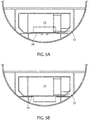
- the technical floor may have a movable portion 34 that is configured to slide open, as illustrated by FIG. 5B .
- the movable portion 34 of the technical floor 32 may be configured to move via mechanical pressure.
- the movable portion 34 of the technical floor 32 may be configured to open automatically via an electrical system.
- the movable portion 34 of the technical floor 32 may be configured to telescope open in at least one portion thereof. This could result in the moveable portion 34 being opened back against a stationary portion of the floor 32.
- the technical floor 32 may have one or more portions 34 that slide or ride over the stationary portion of the floor 32 such that at least a portion of the moveable portion 34 and the stationary portion of the technical floor 32 overlap when opened.
- the second floor surface 20 of the container 10 may be lowered.
- the second floor surface 20 may be vertically raised and/or lowered into the technical floor space created via an electrical system, a pneumatic system, a pulley system, manually via a mechanical system, any combination thereof, or using any other appropriate displacement method.
- lowering of the second floor surface 20 of the container 10 may take place via user pressure from inside the container 10.
- a user may simply need to release a lock feature, and the lowerable portion 20 may release via gravity.
- the floor may be lowered upon activation of a press button or a lever on a user interface, sending a signal to a displacement system to cause movement/electronic floor lowering.
- Lowering of the second floor surface 20 of the container may take place automatically once the technical floor space is created, such that a technical floor movement system interfaces with a container floor lowering system.
- the systems may be mechanically linked such that movement of one system causes related movement of the other system. It should be understood that various lowering or displacement features may be used and are considered within the scope of this disclosure.
- a lock feature that maintains the lowerable second floor portion 20 in its locked position until released.
- the general goal is that when the container 10 is being loaded and/or unloaded, the lowerable floor 20 is retracted and does not interfere with the loading and/or unloading process.
Landscapes
- Engineering & Computer Science (AREA)
- Aviation & Aerospace Engineering (AREA)
- Floor Finish (AREA)
Description
- Embodiments of the present disclosure relate generally to lower deck mobile crew rests and improvements to the user experience and use of space therein.
- Crew rests may be used on some aircraft to offer crew members a resting place on long haul flights. Alternatively, passenger seats may be used, although this means that those seats are unavailable for paying customers and also means the crew does not have a comfortable place to sleep. When needed, lower deck mobile crew rests (LDMCRs) may be installed in an aircraft when possible (i.e., when the aircraft is large enough and there is no cargo in the cargo bay). When not needed, the LDMCR can be removed from the aircraft so the aircraft is able to accommodate more cargo.
- A LDMCR is generally provided as a container-like space that can be loaded and unloaded onto the aircraft. It is generally desirable that the rest area include space, privacy, and comfort for the users. The rest area may include bunk space, stowage space, lavatory space, and other areas. Improvements to LDMCR containers are desirable in order to improve comfort as well as to improve the loading processes of the LDMCR.
WO2007/042276 (Airbus GMBH; Schuld Michael; Kwik Harry) relates to a vertically movable passageway for a space in the ceiling region in an aircraft cabin. In this arrangement the passageway comprises a passageway floor and a displacement device, wherein the displacement device is designed to variably set the height (hi) of the passageway floor. - Embodiments of the invention described herein thus provide systems and methods for improving lower deck mobile crew rests, the user experience, and the use of space therein. There is provided a lower floor with a second floor surface that can be extended and retracted from the lower floor.
- In one example, there is provided a mobile crew rest for an aircraft, according to the features of claim 1. The lowerable portion may comprise an accordion-like connection to the stationary floor portion of the lower floor. The lowerable portion may extend below the stationary floor portion up to about 0.7 meters.
- As shown in the figures, the lower deck mobile crew rest may have one or more bunk spaces in the interior portion, and the lowerable floor portion may move below the bunk or storage spaces, creating more leg space for users. There may be a lock feature provided in order to keep the lowerable floor portion in the retracted position when desired. In use, the lowerable floor portion may be vertically raised or lowered via an electrical system, a pneumatic system, a pulley system, manually via a mechanical system, or any combination thereof. The lowerable floor portion may be lowered into a space created in a cargo bay area technical floor.
- In another example, there is provided a method for using a mobile crew rest in an aircraft having a cargo bay area with a technical floor having a moveable portion, according to the features of
claim 10. -
-
FIG. 1 shows a side plan view of a lower deck mobile crew rest having a lowerable floor portion in a lowered, extended position. -
FIG. 2 shows a side plan view of the lower deck mobile crew rest ofFIG. 1 , with the lowerable floor portion in its retracted, raised position. -
FIG. 3 shows a side perspective view of a lower deck mobile crew rest. -
FIG. 4A shows a side plan view of a lower deck mobile crew rest having an accordion-like lowerable floor portion in the retracted position. -
FIG. 4B shows a side plan view of a lower deck mobile crew rest having an accordion-like lowerable floor portion in the extended position. -
FIG. 5A shows a cargo area of an aircraft having a lower deck mobile crew rest installed, prior to extension of the lowerable floor portion. -
FIG. 5B shows a cargo area of an aircraft having a lower deck mobile crew rest installed, with a portion of the technical floor moved aside. -
FIG. 6 shows a side perspective view of a lower deck mobile crew rest having a lowerable floor portion in a lowered, extended position. -
FIG. 7 shows a side perspective view of a lower deck mobile crew rest having a lowerable floor portion in a raised, retracted position. - Embodiments of the present invention provide a
crew rest container 10 or space configured to enhance the user experience. The crew restcontainer 10 generally has anupper ceiling 12 and alower floor 14. Traditionally, the floors of crew rest spaces are formed as a traditional, flat floor panel. The present disclosure provides alower floor 14 that can be lowered. - Accordingly, the present disclosure provides a
lower floor 14 with asecond floor surface 20 that can be extended and retracted from thelower floor 14. In use, this provides a first stationary floor surface formed by thelower floor 14 at a first level "A" and asecond floor surface 20 formed by the extendable and retractablesecond floor surface 20 at a second level "B". This is illustrated byFIG. 1 . When thecrew rest container 10 is to be loaded onto an aircraft, thesecond floor 20 is retracted, as is shown inFIG. 2 . This provides a flatlower surface 22 for thecontainer 10, which can ease the loading and installation process. Once thecontainer 10 is positioned on-board the aircraft in the desired location, thesecond floor surface 20 may be extended, as is shown inFIGS. 1 and5 . This provides a portion of the floor that is lowered further, which may allow a user to stand upright inside thecontainer 10. - As illustrated by
FIG. 3 , acrew rest container 10 may generally have one ormore bunks 16 and/or one ormore storage spaces 18. Because some of thebunks 16 may be positioned close to thelower floor 14, access to these spaces can be difficult for users. Additionally, mobile crew rests are often provided as being about 1.6 meters in height due to aircraft space considerations. Such a height does not always allow a person to stand fully upright in the rest area. By providing a second,lowerable floor portion 20, a container occupant may be allowed to stand upright. The added space can also help accommodate a ladder for reachingupper bunks 16. In one example, the secondlowerable floor portion 20 may add up to about 0.5 meters to the space. In another example, the secondlowerable floor portion 20 may add between about 0.2 to about 0.7 meters to the space. Greater or lesser spaces may be provided, depending upon aircraft needs and space requirements available. - In one example, the
lower floor 14 of thecontainer 10 may havestationary edges 24. Thesestationary edges 24 may formbunk spaces 16,storage spaces 18, or provide space for any other use. Thesestationary edges 24 do not move when the secondlowerable floor surface 20 is lowered. The area to be lowered is generally positioned interiorly from thestationary edges 24. The area to be lowered may be formed as havingsidewall portions 26 and afloor panel 28. When the lowerable floor is retracted into the interior space of the container 10 (e.g., upon loading) as illustrated byFIG. 2 , the sidewalls are raised, causing thefloor panel 28 to be raised as well. This may cause thefloor panel 28 to actually be positioned above thelower floor 14 or generally level with thelower floor 14. - In one example, when lowered, the
second floor surface 20 may have an accordion-like cooperation with the stationary edges 24. In this example, the accordion-like sides of thelowerable portion 20 are provided as foldable flaps 30. One example of this is illustrated byFIG. 4 . Foldable flaps 30 can fold upon one another upon retraction, as illustrated byFIG. 4A . They can be opened upon expansion of thelowerable portion 20, as illustrated byFIG. 4B . In another example, the walls may be provided as sidewalls that simply rise up and into the interior space of the container. This may render the lowerable portion generally level with the stationarylower floor 14. One example of this is illustrated byFIGS. 1 and 2 , as well asFIGS. 6 and 7 . In either embodiment, it is generally desirable that theflaps 30 and/orsidewalls 26 maintain an airtight connection with thecontainer space 10. This can help prevent debris from hindering extension and retraction, as well as can help maintain the desired pressure within thecontainer 10. - One example of a LDMCR 10 positioned on board an aircraft in the cargo holding area is illustrated by
FIG. 5 . In order to provide space for lowering of thesecond floor surface 20, atechnical floor 32 of the aircraft cargo area may be designed to be movable. For example, the technical floor may have amovable portion 34 that is configured to slide open, as illustrated byFIG. 5B . Themovable portion 34 of thetechnical floor 32 may be configured to move via mechanical pressure. Themovable portion 34 of thetechnical floor 32 may be configured to open automatically via an electrical system. Themovable portion 34 of thetechnical floor 32 may be configured to telescope open in at least one portion thereof. This could result in themoveable portion 34 being opened back against a stationary portion of thefloor 32. For example, thetechnical floor 32 may have one ormore portions 34 that slide or ride over the stationary portion of thefloor 32 such that at least a portion of themoveable portion 34 and the stationary portion of thetechnical floor 32 overlap when opened. In any event, once thetechnical floor 32 has provided the appropriate space, thesecond floor surface 20 of thecontainer 10 may be lowered. - The
second floor surface 20 may be vertically raised and/or lowered into the technical floor space created via an electrical system, a pneumatic system, a pulley system, manually via a mechanical system, any combination thereof, or using any other appropriate displacement method. For example, lowering of thesecond floor surface 20 of thecontainer 10 may take place via user pressure from inside thecontainer 10. A user may simply need to release a lock feature, and thelowerable portion 20 may release via gravity. The floor may be lowered upon activation of a press button or a lever on a user interface, sending a signal to a displacement system to cause movement/electronic floor lowering. Lowering of thesecond floor surface 20 of the container may take place automatically once the technical floor space is created, such that a technical floor movement system interfaces with a container floor lowering system. The systems may be mechanically linked such that movement of one system causes related movement of the other system. It should be understood that various lowering or displacement features may be used and are considered within the scope of this disclosure. - Regardless of the lowering system used, there may be provided a lock feature that maintains the lowerable
second floor portion 20 in its locked position until released. The general goal is that when thecontainer 10 is being loaded and/or unloaded, thelowerable floor 20 is retracted and does not interfere with the loading and/or unloading process. - Changes and modifications, additions and deletions may be made to the structures and methods recited above and shown in the drawings without departing from the scope as defined in the following claims.
Claims (10)
- A mobile crew rest (10) for an aircraft, comprising:an interior crew rest space, anda lower floor (14),characterised in thatthe mobile crew rest is a lower deck mobile crew rest container that is loadable and unloadable onto a lower deck of an aircraft and the lower floor (14) comprises a lowerable floor portion (20) configured to be moveable from a raised position in which the lower deck mobile crew rest container is loadable onto the aircraft to a lowered position once the lower deck mobile crew rest container (10) is installed in the lower deck of an aircraft such that in the lowered position the lower floor (14) comprises a first floor surface at a first level (A) and a second floor surface at a second level (B), the first level (A) being higher than the second level (B).
- The mobile crew rest (10) of claim 1, wherein the second floor surface (20, 28) is generally level with the first floor surface when the portion of the lowerable floor portion (20) is in the raised position.
- The mobile crew rest (10) of either claim 1 or 2, wherein the lowerable portion (20) comprises an accordion-like connection (30) to the first floor surface of the lower floor (14).
- The mobile crew rest (10) of any of the preceding claims, wherein the lowerable floor portion (20) is configured to be retracted into the interior crew rest space.
- The mobile crew rest (10) of any of the preceding claims, wherein the lowerable portion (20) extends below the first floor surface up to about 0.7 meters.
- The mobile crew rest (10) of any of the preceding claims, further comprising one or more bunk spaces (16) in the interior portion, and wherein the lowerable floor portion (20) moves below the bunk (16) or storage spaces (18), creating more leg space for users.
- The mobile crew rest (10) of any of the preceding claims, further comprising a lock feature.
- The mobile crew rest (10) of any of the preceding claims, wherein the lowerable floor portion (20) is vertically raised or lowered via an electrical system, a pneumatic system, a pulley system, manually via a mechanical system, or any combination thereof.
- The mobile crew rest (10) of any of the preceding claims, wherein the lowerable floor portion (20) is lowered into a space created in a cargo bay area technical floor (32).
- A method for using a mobile crew rest (10), according to any of the preceding claims, in an aircraft having a cargo bay area with a technical floor (32) having a moveable portion (34), comprising the steps of:moving the moveable portion (34) of the technical floor (32); andextending the lowerable floor portion (20) into a space created by the movable portion (34).
Applications Claiming Priority (1)
| Application Number | Priority Date | Filing Date | Title |
|---|---|---|---|
| US201462050370P | 2014-09-15 | 2014-09-15 |
Publications (2)
| Publication Number | Publication Date |
|---|---|
| EP2995551A1 EP2995551A1 (en) | 2016-03-16 |
| EP2995551B1 true EP2995551B1 (en) | 2018-02-28 |
Family
ID=54147072
Family Applications (1)
| Application Number | Title | Priority Date | Filing Date |
|---|---|---|---|
| EP15185372.8A Not-in-force EP2995551B1 (en) | 2014-09-15 | 2015-09-15 | Lower deck mobile crew rest with lowered floor |
Country Status (2)
| Country | Link |
|---|---|
| US (1) | US9896209B2 (en) |
| EP (1) | EP2995551B1 (en) |
Families Citing this family (8)
| Publication number | Priority date | Publication date | Assignee | Title |
|---|---|---|---|---|
| EP3170747A1 (en) * | 2015-11-18 | 2017-05-24 | Airbus Operations GmbH | Aircraft for the transport of passengers having lower deck facilities |
| WO2018037268A1 (en) * | 2016-08-24 | 2018-03-01 | Zodiac Aerospace S.A. | Enhanced lower deck commercial cabins |
| DE102017202068A1 (en) * | 2017-02-09 | 2018-08-09 | Airbus Operations Gmbh | Cabin monument for an aircraft |
| DE102017106411B4 (en) * | 2017-03-24 | 2022-05-12 | Airbus Operations Gmbh | Multifunctional container system for producing a container that can be used in an aircraft hold |
| FR3066474B1 (en) * | 2017-05-19 | 2021-06-25 | Zodiac Aerospace | MODULAR ARRANGEMENT INTENDED TO WELCOME AT LEAST ONE PASSENGER OF AN AIRCRAFT AND AIRCRAFT CABIN INCLUDING AT LEAST ONE SUCH MODULAR ARRANGEMENT, ESPECIALLY AT THE LEVEL OF A CARGO ZONE OF THE AIRCRAFT |
| CA3081247A1 (en) | 2019-05-21 | 2020-11-21 | Bombardier Inc. | Aircraft with crew quarters |
| BR112022016092A2 (en) | 2020-02-20 | 2022-10-04 | Air New Zealand Ltd | MULTI-LAYER SLEEPING COMPARTMENT |
| JP1684497S (en) | 2020-02-20 | 2021-05-10 |
Family Cites Families (6)
| Publication number | Priority date | Publication date | Assignee | Title |
|---|---|---|---|---|
| DE2630210C3 (en) * | 1976-07-05 | 1979-10-18 | Hans Guido Dr. 8000 Muenchen Mutke | Device for the horizontal transport of people, in particular in aircraft |
| DE4416506C2 (en) | 1994-05-10 | 1999-12-02 | Daimler Chrysler Aerospace | Passenger plane |
| US6808142B2 (en) * | 2000-06-06 | 2004-10-26 | Mitsubishi Heavy Industries, Ltd. | Aircraft with a plurality of upper and lower cabins functioning as cargo compartments or passenger cabins and method of loading cargos for aircraft |
| US8011617B2 (en) * | 2005-06-17 | 2011-09-06 | Curry James M | Compact cargo lift for commerical aircraft |
| DE102005048709A1 (en) * | 2005-10-12 | 2007-04-26 | Airbus Deutschland Gmbh | Vertically movable corridor for rest rooms in the ceiling area |
| US8888043B1 (en) * | 2012-09-12 | 2014-11-18 | The Boeing Company | Crew bunk system and method |
-
2015
- 2015-09-15 EP EP15185372.8A patent/EP2995551B1/en not_active Not-in-force
- 2015-09-15 US US14/854,526 patent/US9896209B2/en not_active Expired - Fee Related
Non-Patent Citations (1)
| Title |
|---|
| None * |
Also Published As
| Publication number | Publication date |
|---|---|
| EP2995551A1 (en) | 2016-03-16 |
| US20160075432A1 (en) | 2016-03-17 |
| US9896209B2 (en) | 2018-02-20 |
Similar Documents
| Publication | Publication Date | Title |
|---|---|---|
| US9896209B2 (en) | Lower deck mobile crew rest with lowered floor | |
| US10246191B2 (en) | Partition wall for a vehicle cabin, a monument arrangement in a cabin of a transportation means, and a transportation means with a cabin along with at least one such partition wall arranged therein | |
| US8979189B2 (en) | Cantilevered tray table and aircraft passenger suite including the same | |
| EP2939920B1 (en) | Deployable floor panel arrangement for aircraft cabin area | |
| US9435360B2 (en) | Vacuum powered lifting mechanism | |
| US20210179254A1 (en) | Door assembly and seat unit | |
| US20180116391A1 (en) | Table For Aircraft Interiors | |
| EP3786063B1 (en) | Stowable door folding table | |
| CN104229141B (en) | Fold Desk system and include the aircraft of this system | |
| US9340294B1 (en) | Aircraft cabin egress | |
| CN107826232A (en) | Aircraft cabin regions include the aircraft and its operating method of the aircraft cabin regions | |
| JP6782552B2 (en) | Deadweight carousel and method of storing cargo for use on aircraft | |
| EP2956359A1 (en) | Aircraft | |
| US10314285B1 (en) | Platform and guide panel for aircraft cabin egress | |
| US7658577B2 (en) | Fastening device for fastening a movable element | |
| US9605472B2 (en) | Connecting means comprising a hatch and a bellows | |
| KR101563663B1 (en) | Helicopter deck apparatus | |
| US20260015077A1 (en) | Methods, systems, and devices for a door for a vehicle | |
| US9981609B2 (en) | Rotating luggage bin | |
| US9517845B2 (en) | Movable personnel platform for unloading a unit load device | |
| US10647428B2 (en) | Cargo unit for an aircraft and a lower deck catering system | |
| CA2979255C (en) | Quick release hook device for trailers | |
| NO337177B1 (en) | Ramp for forming a temporary transport connection between a ship and a surface |
Legal Events
| Date | Code | Title | Description |
|---|---|---|---|
| PUAI | Public reference made under article 153(3) epc to a published international application that has entered the european phase |
Free format text: ORIGINAL CODE: 0009012 |
|
| AK | Designated contracting states |
Kind code of ref document: A1 Designated state(s): AL AT BE BG CH CY CZ DE DK EE ES FI FR GB GR HR HU IE IS IT LI LT LU LV MC MK MT NL NO PL PT RO RS SE SI SK SM TR |
|
| AX | Request for extension of the european patent |
Extension state: BA ME |
|
| 17P | Request for examination filed |
Effective date: 20160916 |
|
| RBV | Designated contracting states (corrected) |
Designated state(s): AL AT BE BG CH CY CZ DE DK EE ES FI FR GB GR HR HU IE IS IT LI LT LU LV MC MK MT NL NO PL PT RO RS SE SI SK SM TR |
|
| GRAP | Despatch of communication of intention to grant a patent |
Free format text: ORIGINAL CODE: EPIDOSNIGR1 |
|
| INTG | Intention to grant announced |
Effective date: 20170824 |
|
| GRAJ | Information related to disapproval of communication of intention to grant by the applicant or resumption of examination proceedings by the epo deleted |
Free format text: ORIGINAL CODE: EPIDOSDIGR1 |
|
| GRAL | Information related to payment of fee for publishing/printing deleted |
Free format text: ORIGINAL CODE: EPIDOSDIGR3 |
|
| GRAS | Grant fee paid |
Free format text: ORIGINAL CODE: EPIDOSNIGR3 |
|
| GRAR | Information related to intention to grant a patent recorded |
Free format text: ORIGINAL CODE: EPIDOSNIGR71 |
|
| GRAA | (expected) grant |
Free format text: ORIGINAL CODE: 0009210 |
|
| INTC | Intention to grant announced (deleted) | ||
| AK | Designated contracting states |
Kind code of ref document: B1 Designated state(s): AL AT BE BG CH CY CZ DE DK EE ES FI FR GB GR HR HU IE IS IT LI LT LU LV MC MK MT NL NO PL PT RO RS SE SI SK SM TR |
|
| INTG | Intention to grant announced |
Effective date: 20180122 |
|
| REG | Reference to a national code |
Ref country code: GB Ref legal event code: FG4D Ref country code: CH Ref legal event code: EP |
|
| REG | Reference to a national code |
Ref country code: AT Ref legal event code: REF Ref document number: 973805 Country of ref document: AT Kind code of ref document: T Effective date: 20180315 |
|
| REG | Reference to a national code |
Ref country code: IE Ref legal event code: FG4D |
|
| REG | Reference to a national code |
Ref country code: DE Ref legal event code: R096 Ref document number: 602015008278 Country of ref document: DE |
|
| REG | Reference to a national code |
Ref country code: NL Ref legal event code: MP Effective date: 20180228 |
|
| REG | Reference to a national code |
Ref country code: LT Ref legal event code: MG4D |
|
| REG | Reference to a national code |
Ref country code: AT Ref legal event code: MK05 Ref document number: 973805 Country of ref document: AT Kind code of ref document: T Effective date: 20180228 |
|
| PG25 | Lapsed in a contracting state [announced via postgrant information from national office to epo] |
Ref country code: ES Free format text: LAPSE BECAUSE OF FAILURE TO SUBMIT A TRANSLATION OF THE DESCRIPTION OR TO PAY THE FEE WITHIN THE PRESCRIBED TIME-LIMIT Effective date: 20180228 Ref country code: NO Free format text: LAPSE BECAUSE OF FAILURE TO SUBMIT A TRANSLATION OF THE DESCRIPTION OR TO PAY THE FEE WITHIN THE PRESCRIBED TIME-LIMIT Effective date: 20180528 Ref country code: FI Free format text: LAPSE BECAUSE OF FAILURE TO SUBMIT A TRANSLATION OF THE DESCRIPTION OR TO PAY THE FEE WITHIN THE PRESCRIBED TIME-LIMIT Effective date: 20180228 Ref country code: HR Free format text: LAPSE BECAUSE OF FAILURE TO SUBMIT A TRANSLATION OF THE DESCRIPTION OR TO PAY THE FEE WITHIN THE PRESCRIBED TIME-LIMIT Effective date: 20180228 Ref country code: NL Free format text: LAPSE BECAUSE OF FAILURE TO SUBMIT A TRANSLATION OF THE DESCRIPTION OR TO PAY THE FEE WITHIN THE PRESCRIBED TIME-LIMIT Effective date: 20180228 Ref country code: CY Free format text: LAPSE BECAUSE OF FAILURE TO SUBMIT A TRANSLATION OF THE DESCRIPTION OR TO PAY THE FEE WITHIN THE PRESCRIBED TIME-LIMIT Effective date: 20180228 Ref country code: LT Free format text: LAPSE BECAUSE OF FAILURE TO SUBMIT A TRANSLATION OF THE DESCRIPTION OR TO PAY THE FEE WITHIN THE PRESCRIBED TIME-LIMIT Effective date: 20180228 |
|
| REG | Reference to a national code |
Ref country code: FR Ref legal event code: PLFP Year of fee payment: 4 |
|
| PG25 | Lapsed in a contracting state [announced via postgrant information from national office to epo] |
Ref country code: LV Free format text: LAPSE BECAUSE OF FAILURE TO SUBMIT A TRANSLATION OF THE DESCRIPTION OR TO PAY THE FEE WITHIN THE PRESCRIBED TIME-LIMIT Effective date: 20180228 Ref country code: SE Free format text: LAPSE BECAUSE OF FAILURE TO SUBMIT A TRANSLATION OF THE DESCRIPTION OR TO PAY THE FEE WITHIN THE PRESCRIBED TIME-LIMIT Effective date: 20180228 Ref country code: BG Free format text: LAPSE BECAUSE OF FAILURE TO SUBMIT A TRANSLATION OF THE DESCRIPTION OR TO PAY THE FEE WITHIN THE PRESCRIBED TIME-LIMIT Effective date: 20180528 Ref country code: RS Free format text: LAPSE BECAUSE OF FAILURE TO SUBMIT A TRANSLATION OF THE DESCRIPTION OR TO PAY THE FEE WITHIN THE PRESCRIBED TIME-LIMIT Effective date: 20180228 Ref country code: GR Free format text: LAPSE BECAUSE OF FAILURE TO SUBMIT A TRANSLATION OF THE DESCRIPTION OR TO PAY THE FEE WITHIN THE PRESCRIBED TIME-LIMIT Effective date: 20180529 Ref country code: AT Free format text: LAPSE BECAUSE OF FAILURE TO SUBMIT A TRANSLATION OF THE DESCRIPTION OR TO PAY THE FEE WITHIN THE PRESCRIBED TIME-LIMIT Effective date: 20180228 |
|
| PG25 | Lapsed in a contracting state [announced via postgrant information from national office to epo] |
Ref country code: RO Free format text: LAPSE BECAUSE OF FAILURE TO SUBMIT A TRANSLATION OF THE DESCRIPTION OR TO PAY THE FEE WITHIN THE PRESCRIBED TIME-LIMIT Effective date: 20180228 Ref country code: EE Free format text: LAPSE BECAUSE OF FAILURE TO SUBMIT A TRANSLATION OF THE DESCRIPTION OR TO PAY THE FEE WITHIN THE PRESCRIBED TIME-LIMIT Effective date: 20180228 Ref country code: IT Free format text: LAPSE BECAUSE OF FAILURE TO SUBMIT A TRANSLATION OF THE DESCRIPTION OR TO PAY THE FEE WITHIN THE PRESCRIBED TIME-LIMIT Effective date: 20180228 Ref country code: AL Free format text: LAPSE BECAUSE OF FAILURE TO SUBMIT A TRANSLATION OF THE DESCRIPTION OR TO PAY THE FEE WITHIN THE PRESCRIBED TIME-LIMIT Effective date: 20180228 Ref country code: PL Free format text: LAPSE BECAUSE OF FAILURE TO SUBMIT A TRANSLATION OF THE DESCRIPTION OR TO PAY THE FEE WITHIN THE PRESCRIBED TIME-LIMIT Effective date: 20180228 |
|
| REG | Reference to a national code |
Ref country code: DE Ref legal event code: R097 Ref document number: 602015008278 Country of ref document: DE |
|
| PG25 | Lapsed in a contracting state [announced via postgrant information from national office to epo] |
Ref country code: DK Free format text: LAPSE BECAUSE OF FAILURE TO SUBMIT A TRANSLATION OF THE DESCRIPTION OR TO PAY THE FEE WITHIN THE PRESCRIBED TIME-LIMIT Effective date: 20180228 Ref country code: SK Free format text: LAPSE BECAUSE OF FAILURE TO SUBMIT A TRANSLATION OF THE DESCRIPTION OR TO PAY THE FEE WITHIN THE PRESCRIBED TIME-LIMIT Effective date: 20180228 Ref country code: CZ Free format text: LAPSE BECAUSE OF FAILURE TO SUBMIT A TRANSLATION OF THE DESCRIPTION OR TO PAY THE FEE WITHIN THE PRESCRIBED TIME-LIMIT Effective date: 20180228 Ref country code: SM Free format text: LAPSE BECAUSE OF FAILURE TO SUBMIT A TRANSLATION OF THE DESCRIPTION OR TO PAY THE FEE WITHIN THE PRESCRIBED TIME-LIMIT Effective date: 20180228 |
|
| PLBE | No opposition filed within time limit |
Free format text: ORIGINAL CODE: 0009261 |
|
| STAA | Information on the status of an ep patent application or granted ep patent |
Free format text: STATUS: NO OPPOSITION FILED WITHIN TIME LIMIT |
|
| 26N | No opposition filed |
Effective date: 20181129 |
|
| PG25 | Lapsed in a contracting state [announced via postgrant information from national office to epo] |
Ref country code: SI Free format text: LAPSE BECAUSE OF FAILURE TO SUBMIT A TRANSLATION OF THE DESCRIPTION OR TO PAY THE FEE WITHIN THE PRESCRIBED TIME-LIMIT Effective date: 20180228 |
|
| PG25 | Lapsed in a contracting state [announced via postgrant information from national office to epo] |
Ref country code: MC Free format text: LAPSE BECAUSE OF FAILURE TO SUBMIT A TRANSLATION OF THE DESCRIPTION OR TO PAY THE FEE WITHIN THE PRESCRIBED TIME-LIMIT Effective date: 20180228 |
|
| REG | Reference to a national code |
Ref country code: CH Ref legal event code: PL |
|
| REG | Reference to a national code |
Ref country code: BE Ref legal event code: MM Effective date: 20180930 |
|
| REG | Reference to a national code |
Ref country code: IE Ref legal event code: MM4A |
|
| PG25 | Lapsed in a contracting state [announced via postgrant information from national office to epo] |
Ref country code: LU Free format text: LAPSE BECAUSE OF NON-PAYMENT OF DUE FEES Effective date: 20180915 |
|
| PG25 | Lapsed in a contracting state [announced via postgrant information from national office to epo] |
Ref country code: IE Free format text: LAPSE BECAUSE OF NON-PAYMENT OF DUE FEES Effective date: 20180915 |
|
| PG25 | Lapsed in a contracting state [announced via postgrant information from national office to epo] |
Ref country code: BE Free format text: LAPSE BECAUSE OF NON-PAYMENT OF DUE FEES Effective date: 20180930 Ref country code: CH Free format text: LAPSE BECAUSE OF NON-PAYMENT OF DUE FEES Effective date: 20180930 Ref country code: LI Free format text: LAPSE BECAUSE OF NON-PAYMENT OF DUE FEES Effective date: 20180930 |
|
| PG25 | Lapsed in a contracting state [announced via postgrant information from national office to epo] |
Ref country code: MT Free format text: LAPSE BECAUSE OF NON-PAYMENT OF DUE FEES Effective date: 20180915 |
|
| PG25 | Lapsed in a contracting state [announced via postgrant information from national office to epo] |
Ref country code: TR Free format text: LAPSE BECAUSE OF FAILURE TO SUBMIT A TRANSLATION OF THE DESCRIPTION OR TO PAY THE FEE WITHIN THE PRESCRIBED TIME-LIMIT Effective date: 20180228 |
|
| PG25 | Lapsed in a contracting state [announced via postgrant information from national office to epo] |
Ref country code: PT Free format text: LAPSE BECAUSE OF FAILURE TO SUBMIT A TRANSLATION OF THE DESCRIPTION OR TO PAY THE FEE WITHIN THE PRESCRIBED TIME-LIMIT Effective date: 20180228 |
|
| PG25 | Lapsed in a contracting state [announced via postgrant information from national office to epo] |
Ref country code: MK Free format text: LAPSE BECAUSE OF NON-PAYMENT OF DUE FEES Effective date: 20180228 Ref country code: HU Free format text: LAPSE BECAUSE OF FAILURE TO SUBMIT A TRANSLATION OF THE DESCRIPTION OR TO PAY THE FEE WITHIN THE PRESCRIBED TIME-LIMIT; INVALID AB INITIO Effective date: 20150915 |
|
| PG25 | Lapsed in a contracting state [announced via postgrant information from national office to epo] |
Ref country code: IS Free format text: LAPSE BECAUSE OF FAILURE TO SUBMIT A TRANSLATION OF THE DESCRIPTION OR TO PAY THE FEE WITHIN THE PRESCRIBED TIME-LIMIT Effective date: 20180628 |
|
| GBPC | Gb: european patent ceased through non-payment of renewal fee |
Effective date: 20190915 |
|
| PG25 | Lapsed in a contracting state [announced via postgrant information from national office to epo] |
Ref country code: GB Free format text: LAPSE BECAUSE OF NON-PAYMENT OF DUE FEES Effective date: 20190915 |
|
| PGFP | Annual fee paid to national office [announced via postgrant information from national office to epo] |
Ref country code: DE Payment date: 20200819 Year of fee payment: 6 Ref country code: FR Payment date: 20200819 Year of fee payment: 6 |
|
| REG | Reference to a national code |
Ref country code: DE Ref legal event code: R082 Ref document number: 602015008278 Country of ref document: DE Representative=s name: GODEMEYER BLUM LENZE PATENTANWAELTE, PARTNERSC, DE Ref country code: DE Ref legal event code: R081 Ref document number: 602015008278 Country of ref document: DE Owner name: SAFRAN CABIN NETHERLANDS N.V., NL Free format text: FORMER OWNER: DRIESSEN AEROSPACE GROUP N.V., ALKMAAR, NL |
|
| REG | Reference to a national code |
Ref country code: DE Ref legal event code: R119 Ref document number: 602015008278 Country of ref document: DE |
|
| PG25 | Lapsed in a contracting state [announced via postgrant information from national office to epo] |
Ref country code: FR Free format text: LAPSE BECAUSE OF NON-PAYMENT OF DUE FEES Effective date: 20210930 Ref country code: DE Free format text: LAPSE BECAUSE OF NON-PAYMENT OF DUE FEES Effective date: 20220401 |