EP2995547A2 - Method and apparatus for drilling multiple subsea wells from an offshore platform at a single site - Google Patents
Method and apparatus for drilling multiple subsea wells from an offshore platform at a single site Download PDFInfo
- Publication number
- EP2995547A2 EP2995547A2 EP15191275.5A EP15191275A EP2995547A2 EP 2995547 A2 EP2995547 A2 EP 2995547A2 EP 15191275 A EP15191275 A EP 15191275A EP 2995547 A2 EP2995547 A2 EP 2995547A2
- Authority
- EP
- European Patent Office
- Prior art keywords
- drilling riser
- deck
- drilling
- platform according
- tension leg
- Prior art date
- Legal status (The legal status is an assumption and is not a legal conclusion. Google has not performed a legal analysis and makes no representation as to the accuracy of the status listed.)
- Withdrawn
Links
Images




Classifications
-
- E—FIXED CONSTRUCTIONS
- E21—EARTH OR ROCK DRILLING; MINING
- E21B—EARTH OR ROCK DRILLING; OBTAINING OIL, GAS, WATER, SOLUBLE OR MELTABLE MATERIALS OR A SLURRY OF MINERALS FROM WELLS
- E21B7/00—Special methods or apparatus for drilling
- E21B7/12—Underwater drilling
-
- B—PERFORMING OPERATIONS; TRANSPORTING
- B63—SHIPS OR OTHER WATERBORNE VESSELS; RELATED EQUIPMENT
- B63B—SHIPS OR OTHER WATERBORNE VESSELS; EQUIPMENT FOR SHIPPING
- B63B21/00—Tying-up; Shifting, towing, or pushing equipment; Anchoring
- B63B21/50—Anchoring arrangements or methods for special vessels, e.g. for floating drilling platforms or dredgers
- B63B21/502—Anchoring arrangements or methods for special vessels, e.g. for floating drilling platforms or dredgers by means of tension legs
-
- B—PERFORMING OPERATIONS; TRANSPORTING
- B63—SHIPS OR OTHER WATERBORNE VESSELS; RELATED EQUIPMENT
- B63B—SHIPS OR OTHER WATERBORNE VESSELS; EQUIPMENT FOR SHIPPING
- B63B27/00—Arrangement of ship-based loading or unloading equipment for cargo or passengers
- B63B27/19—Other loading or unloading equipment involving an intermittent action, not provided in groups B63B27/04 - B63B27/18
-
- B—PERFORMING OPERATIONS; TRANSPORTING
- B63—SHIPS OR OTHER WATERBORNE VESSELS; RELATED EQUIPMENT
- B63B—SHIPS OR OTHER WATERBORNE VESSELS; EQUIPMENT FOR SHIPPING
- B63B35/00—Vessels or similar floating structures specially adapted for specific purposes and not otherwise provided for
- B63B35/44—Floating buildings, stores, drilling platforms, or workshops, e.g. carrying water-oil separating devices
- B63B35/4413—Floating drilling platforms, e.g. carrying water-oil separating devices
-
- E—FIXED CONSTRUCTIONS
- E21—EARTH OR ROCK DRILLING; MINING
- E21B—EARTH OR ROCK DRILLING; OBTAINING OIL, GAS, WATER, SOLUBLE OR MELTABLE MATERIALS OR A SLURRY OF MINERALS FROM WELLS
- E21B15/00—Supports for the drilling machine, e.g. derricks or masts
- E21B15/003—Supports for the drilling machine, e.g. derricks or masts adapted to be moved on their substructure, e.g. with skidding means; adapted to drill a plurality of wells
-
- E—FIXED CONSTRUCTIONS
- E21—EARTH OR ROCK DRILLING; MINING
- E21B—EARTH OR ROCK DRILLING; OBTAINING OIL, GAS, WATER, SOLUBLE OR MELTABLE MATERIALS OR A SLURRY OF MINERALS FROM WELLS
- E21B15/00—Supports for the drilling machine, e.g. derricks or masts
- E21B15/02—Supports for the drilling machine, e.g. derricks or masts specially adapted for underwater drilling
-
- E—FIXED CONSTRUCTIONS
- E21—EARTH OR ROCK DRILLING; MINING
- E21B—EARTH OR ROCK DRILLING; OBTAINING OIL, GAS, WATER, SOLUBLE OR MELTABLE MATERIALS OR A SLURRY OF MINERALS FROM WELLS
- E21B19/00—Handling rods, casings, tubes or the like outside the borehole, e.g. in the derrick; Apparatus for feeding the rods or cables
- E21B19/002—Handling rods, casings, tubes or the like outside the borehole, e.g. in the derrick; Apparatus for feeding the rods or cables specially adapted for underwater drilling
- E21B19/004—Handling rods, casings, tubes or the like outside the borehole, e.g. in the derrick; Apparatus for feeding the rods or cables specially adapted for underwater drilling supporting a riser from a drilling or production platform
-
- E—FIXED CONSTRUCTIONS
- E21—EARTH OR ROCK DRILLING; MINING
- E21B—EARTH OR ROCK DRILLING; OBTAINING OIL, GAS, WATER, SOLUBLE OR MELTABLE MATERIALS OR A SLURRY OF MINERALS FROM WELLS
- E21B19/00—Handling rods, casings, tubes or the like outside the borehole, e.g. in the derrick; Apparatus for feeding the rods or cables
- E21B19/002—Handling rods, casings, tubes or the like outside the borehole, e.g. in the derrick; Apparatus for feeding the rods or cables specially adapted for underwater drilling
- E21B19/004—Handling rods, casings, tubes or the like outside the borehole, e.g. in the derrick; Apparatus for feeding the rods or cables specially adapted for underwater drilling supporting a riser from a drilling or production platform
- E21B19/006—Handling rods, casings, tubes or the like outside the borehole, e.g. in the derrick; Apparatus for feeding the rods or cables specially adapted for underwater drilling supporting a riser from a drilling or production platform including heave compensators
-
- E—FIXED CONSTRUCTIONS
- E21—EARTH OR ROCK DRILLING; MINING
- E21B—EARTH OR ROCK DRILLING; OBTAINING OIL, GAS, WATER, SOLUBLE OR MELTABLE MATERIALS OR A SLURRY OF MINERALS FROM WELLS
- E21B19/00—Handling rods, casings, tubes or the like outside the borehole, e.g. in the derrick; Apparatus for feeding the rods or cables
- E21B19/02—Rod or cable suspensions
-
- E—FIXED CONSTRUCTIONS
- E21—EARTH OR ROCK DRILLING; MINING
- E21B—EARTH OR ROCK DRILLING; OBTAINING OIL, GAS, WATER, SOLUBLE OR MELTABLE MATERIALS OR A SLURRY OF MINERALS FROM WELLS
- E21B19/00—Handling rods, casings, tubes or the like outside the borehole, e.g. in the derrick; Apparatus for feeding the rods or cables
- E21B19/08—Apparatus for feeding the rods or cables; Apparatus for increasing or decreasing the pressure on the drilling tool; Apparatus for counterbalancing the weight of the rods
-
- E—FIXED CONSTRUCTIONS
- E21—EARTH OR ROCK DRILLING; MINING
- E21B—EARTH OR ROCK DRILLING; OBTAINING OIL, GAS, WATER, SOLUBLE OR MELTABLE MATERIALS OR A SLURRY OF MINERALS FROM WELLS
- E21B33/00—Sealing or packing boreholes or wells
- E21B33/02—Surface sealing or packing
- E21B33/03—Well heads; Setting-up thereof
- E21B33/06—Blow-out preventers, i.e. apparatus closing around a drill pipe, e.g. annular blow-out preventers
-
- E—FIXED CONSTRUCTIONS
- E21—EARTH OR ROCK DRILLING; MINING
- E21B—EARTH OR ROCK DRILLING; OBTAINING OIL, GAS, WATER, SOLUBLE OR MELTABLE MATERIALS OR A SLURRY OF MINERALS FROM WELLS
- E21B41/00—Equipment or details not covered by groups E21B15/00 - E21B40/00
- E21B41/10—Guide posts, e.g. releasable; Attaching guide lines to underwater guide bases
-
- E—FIXED CONSTRUCTIONS
- E21—EARTH OR ROCK DRILLING; MINING
- E21B—EARTH OR ROCK DRILLING; OBTAINING OIL, GAS, WATER, SOLUBLE OR MELTABLE MATERIALS OR A SLURRY OF MINERALS FROM WELLS
- E21B7/00—Special methods or apparatus for drilling
- E21B7/12—Underwater drilling
- E21B7/128—Underwater drilling from floating support with independent underwater anchored guide base
-
- E—FIXED CONSTRUCTIONS
- E21—EARTH OR ROCK DRILLING; MINING
- E21B—EARTH OR ROCK DRILLING; OBTAINING OIL, GAS, WATER, SOLUBLE OR MELTABLE MATERIALS OR A SLURRY OF MINERALS FROM WELLS
- E21B7/00—Special methods or apparatus for drilling
- E21B7/12—Underwater drilling
- E21B7/132—Underwater drilling from underwater buoyant support
-
- B—PERFORMING OPERATIONS; TRANSPORTING
- B63—SHIPS OR OTHER WATERBORNE VESSELS; RELATED EQUIPMENT
- B63B—SHIPS OR OTHER WATERBORNE VESSELS; EQUIPMENT FOR SHIPPING
- B63B35/00—Vessels or similar floating structures specially adapted for specific purposes and not otherwise provided for
- B63B35/44—Floating buildings, stores, drilling platforms, or workshops, e.g. carrying water-oil separating devices
- B63B2035/442—Spar-type semi-submersible structures, i.e. shaped as single slender, e.g. substantially cylindrical or trussed vertical bodies
Definitions
- This invention relates to offshore drilling and production platforms. More particularly, it relates to a method and apparatus for drilling a plurality of wells at a single platform (or vessel) location and installing production risers on those wells.
- TLP tension leg platforms
- semis semi-submersible floating vessels
- a tension leg platform is a vertically moored floating structure typically used for the offshore production of oil and/or gas, and is particularly suited for water depths greater than about 1000 ft.
- the platform is permanently moored by tethers or tendons grouped at each of the structure's corners.
- a group of tethers is called a tension leg.
- the tethers have relatively high axial stiffness (low elasticity) such that virtually all vertical motion of the platform is eliminated. This allows the platform to have the production wellheads on deck (connected directly to the subsea wells by rigid risers), instead of on the seafloor. This feature enables less expensive well completions and allows better control over the production from the oil or gas reservoir.
- a semi-submersible is a particular type of floating vessel that is supported primarily on large pontoon-like structures that are submerged below the sea surface.
- the operating decks are elevated perhaps 100 or more feet above the pontoons on large steel columns.
- This design has the advantage of submerging most of the area of components in contact with the sea thereby minimizing loading from wind, waves and currents.
- Semi-submersibles can operate in a wide range of water depths, including deep water.
- the unit may stay on location using dynamic positioning (DP) and/or be anchored by means of catenary mooring lines terminating in piles or anchors in the seafloor.
- DP dynamic positioning
- Semi-submersibles can be used for drilling, workover operations, and production platforms, depending on the equipment with which they are equipped. When fitted with a drilling package, they are typically called semi-submersible drilling rigs.
- DeepDraftSemi® vessel offered by SBM Atlantia, Inc. (Houston, Texas) is a semi-submersible fitted with oil and gas production facilities that is suitable for use in ultra deep water conditions.
- the unit is designed to optimize vessel motions to accommodate steel catenary risers (SCRs).
- a floating, offshore drilling and/or production platform is equipped with a rail-mounted transport system that can be positioned at a plurality of selected positions over the well bay of the vessel.
- the transport system can move a drilling riser with a drilling riser tensioner system and a blowout preventer from one drilling location to another without removing them from the well bay of the vessel.
- the drilling riser is lifted just clear of a first well head and positioned over an adjacent, second well head using guidelines.
- the transport system may then move the upper end of the drilling riser (together with its attached tensioner and BOP) to a second drilling location.
- a dummy wellhead may be provided on the seafloor in order to secure the lower end of the drilling riser without removing it from the sea while production risers are being installed.
- the invention may best be understood by reference to one particular preferred embodiment whose apparatus is illustrated in Figures 1 - 7 and an associated method of use is illustrated in Figure 8 as a sequence of steps.
- the drawing figures outline general equipment and methodology for drilling multiple wells from a floating unit, and the installation of production risers, while minimizing or eliminating the need to retrieve the drilling riser when moving between wells.
- One particular feature of the system is a transfer trolley, which is suspended from the lower deck (the production deck) of the floating platform.
- the transfer trolley is set to run down the length of the well pattern.
- the position of the transfer trolley is held side to side by fixed rails, or similar, which may form part of the deck structure.
- the end-to-end position of the transfer trolley may be shifted using a rack-and-pinion arrangement with the pinion(s) turned by hydraulic motors or the like.
- the end-to-end position of the transfer trolley may be controlled by other means - for example by a pair of opposing winches used to translate the transfer trolley.
- the transfer trolley may be used to transport the assembled drilling riser together with an associated tensioner and blowout preventer (BOP) between well bay positions.
- BOP tensioner and blowout preventer
- the production deck (the lower deck) of the floating structure may contain discrete (separate) tensioners 42 for the near-vertical production risers. These tensioners may be arranged in a regular geometric pattern, as shown in Figures 1 . It should be noted that the spacing of the well bay on the structure may be chosen to be consistent with the physical requirements to fit production tensioners, surface trees, connection jumpers, and other required equipment for drilling, production, work over and so forth.
- the wells may be spaced on the seafloor to provide access space as required for various seafloor activities related to drilling, production, etc.
- the seafloor and surface spacing may not necessarily be identical (due to different space requirements) but may be established in a way to minimize the offset angles between corresponding seafloor and surface locations.
- the TLP includes provision for installation of a total of 27 riser tensioners in a 9-by-3 array of well slots 20 on the lower deck 82 of a TLP.
- the drilling riser is deployed only from the central of the three columns, with the ability to reach each of the 27 subsea well head locations from at least one of the nine positions within the central column. For certain well patterns, less than the full 9 central column positions may be needed to reach each of the wells on the seafloor.
- the central column may initially be open to allow translation of the hanging drilling riser to locations appropriate for reaching the well heads.
- Production risers in the two outer columns may be installed first, with tensioners 42 and surface trees 40 mounted on the lower deck (production deck) 82.
- Tree access platforms 16 may be provided in production deck structure 18.
- Figure 1 shows the outer columns with all production risers installed, a single production riser installed at one end of the central column, and the drilling riser 36 near the midpoint of the central column.
- Figure 1 also shows a smaller BOP 28 (used for well completion) on a Production Riser Tensioner 42 (connected to production riser tension joint 44) in the outer row adjacent to the larger drilling BOP 26, confirming adequate clearance between the two BOP's.
- FIG 2 shows the production deck 82 of a TLP equipped with a drilling riser transport system according to the invention viewed from the opposite end of the well bay as that shown in Figure 1 and with the topsides structure (drilling deck) in place.
- the two winches 22 shown at the near end of the opening in the lower deck 82 are for the drilling riser guidelines 24.
- This view also shows the routing of the production 10, annulus 14 and control jumpers 12 for each of the surface trees. These jumpers are routed outward on the two outer columns of wells.
- the boxes 84 above the central (open) column represent the tie off locations for the central wells. Note that there is ample clearance for hook up of hard piping to the drilling BOP 26.
- FIG. 3 The leftmost illustration in Figure 3 is a side view of a drilling riser assembly comprising drilling riser tension joint 36, a drilling riser tensioner system 30 and a high-pressure blowout preventer (BOP) 26 supported in a drilling riser transfer system 32 according to the invention.
- BOP blowout preventer
- the support inserts for both the production tensioners 42 and drilling riser tensioner 32 may rest on brackets 38 extending outward from the main beams 64 along the edges of the opening in the lower deck.
- the drilling riser 36 may be moved by means of a transporter 32 which fits around the Drilling Riser Transport (DRT) support insert 66 and can lift it clear of the support brackets 38.
- DTR Drilling Riser Transport
- Winches 22 may be constant tension winches.
- Guide wire rope 24 may be routed around sheave 86 and through openings in drilling riser tensioner 30 and hole 62 (see Figure 6 ) in transport trolley 32.
- the transporter 32 may move the drilling riser assembly (26 + 30 + 36 in Figure 3 ) on rails 34 ( Figure 1 ) by means of a rack-and-pinion drive system, located on the edges of the opening in the lower deck.
- Racks 70 may be attached to well bay support beams 64 and/or tracks 72 and pinions 68 may be mounted on transport trolley 32 and connected to hydraulic drive motors 52.
- the transporter may be supported by Hilman rollers 54 (Hilman Inc., Marlboro, NJ 07746) resting on horizontal tracks 72.
- the drive system of the illustrated embodiment uses four drive motors.
- the motion of the transporter may be controlled by guide rollers (not shown) reacting on the sides of the track on one or both sides of the opening in the lower deck.
- adaptor frame 66 is shown in the retracted position.
- the extended position of the adaptor frame 66 is shown in phantom in the lower left view of Figure 4 .
- the adaptor frame 66 is supported by deck support brackets 38 and not (to any significant degree) by transport trolley 32.
- the retracted position of adaptor frame 66 is that used during drilling operations.
- the reactive force of the drilling riser tensioner system 30 is transmitted to the deck structure 64 via deck support brackets 38.
- the supports of transport trolley 32 e.g., Hilman rollers 54 and support arms 88) are not exposed to the dynamic loads of heave compensation imposed by tensioner system 30.
- Figure 5 is similar to Figure 4 , but with adaptor frame 66 in the extended position.
- the DRT support insert 66 may be lifted relative to the transporter 32 by four hydraulic cylinders 66, two on each side of the insert.
- the geometric shape of the support insert and the transporter may be such that overlap between the two parts provides guidance as the support insert rises, limiting lateral loads on the hydraulic cylinders.
- Extending adapter frame 66 results in lifting the drilling riser assembly sufficiently to clear the wellhead on the seafloor to which is was connected. This permits the drilling riser assembly to be moved horizontally within the well bay without disconnecting either the drilling BOP 26 or the drilling riser tensioner system 30. Moreover, the drilling riser itself may remain in the sea. In certain embodiments, a dummy wellhead may be provided on the seafloor for landing and securing the lower end of the drilling riser while production risers are run. This can help to prevent collisions between the risers.
- Figure 6 contains four views of a transport trolley 32 according to one embodiment of the invention -- an isometric view, a top plan view, a side view and an end view.
- Adapter frame lift cylinders 60 are shown within transport trolley 32.
- openings 62 for guidelines 24 which may be sized to also permit passage of the remote ROV guide post tops (see Figure 8 ).
- Figure 7 contains four views of an adapter frame 66 according to one embodiment of the invention -- an isometric view, a top plan view, a side view and an end view.
- Adapter frame 66 has a central opening 67 with a perimeter rim 74 which may project into opening 67.
- Rim (or flange) 74 may be sized and configured to fit drilling riser tensioner system 30. Drilling riser tensioner system 30 is supported on rim 74.
- Load brackets 80 are sized and configured to engage deck support brackets 38.
- Lift extensions 78 are sized and configured to engage adapter frame lift cylinders 60.
- load extensions 80 may be reinforced with gussets 90.
- the transfer method begins at Step 1 with the drilling riser and its associated tieback connector attached to a home position wellhead.
- the guidelines are slackened so that the ROV can unlock the upper section of the guideposts ("guide post tops") and move them to the adjacent wellhead.
- the guide arms may be folded down (using the ROV) and the guidelines reattached to the drilling riser by positioning the guidelines in the lower guide arms via gates in the guide arms.
- the tieback is disconnected from the home position wellhead and lifted by extending the adapter frame lift cylinders 60.
- the transporter 32 may concurrently move the drilling riser to the closest available drilling position over the target wellhead.
- the lower guide arms may be free to swivel around the tie back connector to align and connect with the guidelines and guideposts.
- the guide arms may be sized such that, in the folded position, they may pass through passageways in the drilling riser tensioner and openings 67 in drilling riser transfer trolley 32.
- the drilling riser may be lowered (Step 5) by retracting hydraulic lift cylinders 60, and the tie back connector landed and locked on the adjacent wellhead.
Landscapes
- Engineering & Computer Science (AREA)
- Geology (AREA)
- Life Sciences & Earth Sciences (AREA)
- Mining & Mineral Resources (AREA)
- Geochemistry & Mineralogy (AREA)
- Fluid Mechanics (AREA)
- Environmental & Geological Engineering (AREA)
- General Life Sciences & Earth Sciences (AREA)
- Physics & Mathematics (AREA)
- Mechanical Engineering (AREA)
- Chemical & Material Sciences (AREA)
- Combustion & Propulsion (AREA)
- Ocean & Marine Engineering (AREA)
- Architecture (AREA)
- Civil Engineering (AREA)
- Structural Engineering (AREA)
- Earth Drilling (AREA)
Abstract
Description
- This application claims the benefit of
U.S. Provisional Application No. 61/543,663, filed on October 5, 2011 U.S. Provisional Application No. 61/606,031 U.S. Provisional Application No. 61/610,805, filed on March 14, 2012 - This invention relates to offshore drilling and production platforms. More particularly, it relates to a method and apparatus for drilling a plurality of wells at a single platform (or vessel) location and installing production risers on those wells.
- Both tension leg platforms (TLP's) and semi-submersible floating vessels ("semis") can be used for offshore drilling and production operations.
- A tension leg platform (TLP) is a vertically moored floating structure typically used for the offshore production of oil and/or gas, and is particularly suited for water depths greater than about 1000 ft.
- The platform is permanently moored by tethers or tendons grouped at each of the structure's corners. A group of tethers is called a tension leg. The tethers have relatively high axial stiffness (low elasticity) such that virtually all vertical motion of the platform is eliminated. This allows the platform to have the production wellheads on deck (connected directly to the subsea wells by rigid risers), instead of on the seafloor. This feature enables less expensive well completions and allows better control over the production from the oil or gas reservoir.
- A semi-submersible is a particular type of floating vessel that is supported primarily on large pontoon-like structures that are submerged below the sea surface. The operating decks are elevated perhaps 100 or more feet above the pontoons on large steel columns. This design has the advantage of submerging most of the area of components in contact with the sea thereby minimizing loading from wind, waves and currents. Semi-submersibles can operate in a wide range of water depths, including deep water. The unit may stay on location using dynamic positioning (DP) and/or be anchored by means of catenary mooring lines terminating in piles or anchors in the seafloor. Semi-submersibles can be used for drilling, workover operations, and production platforms, depending on the equipment with which they are equipped. When fitted with a drilling package, they are typically called semi-submersible drilling rigs.
- The DeepDraftSemi® vessel offered by SBM Atlantia, Inc. (Houston, Texas) is a semi-submersible fitted with oil and gas production facilities that is suitable for use in ultra deep water conditions. The unit is designed to optimize vessel motions to accommodate steel catenary risers (SCRs).
- A floating, offshore drilling and/or production platform is equipped with a rail-mounted transport system that can be positioned at a plurality of selected positions over the well bay of the vessel. The transport system can move a drilling riser with a drilling riser tensioner system and a blowout preventer from one drilling location to another without removing them from the well bay of the vessel. Using the transport system, the drilling riser is lifted just clear of a first well head and positioned over an adjacent, second well head using guidelines. The transport system may then move the upper end of the drilling riser (together with its attached tensioner and BOP) to a second drilling location. A dummy wellhead may be provided on the seafloor in order to secure the lower end of the drilling riser without removing it from the sea while production risers are being installed.
-
-
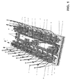
Figure 1 is a perspective view of an isolated well bay on an offshore drilling platform according to one particular embodiment of the invention that provides for 27 production riser tensioners and up to nine locations of a moveable drilling riser tensioner and blowout preventer. -
Figure 2 shows the well bay illustrated inFigure 1 installed in the lower deck ("production deck") of a TLP. -
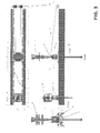
Figure 3 shows both a production riser tensioner and surface tree assembly as well as a drilling riser tension joint, drilling riser tensioner and blowout preventer assembly on a transport trolley according to the invention. -
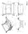
Figure 4 shows various views of an adapter frame in the retracted (drilling) position within a transport trolley according to the invention. -
Figure 5 shows various views of an adapter frame in the extended (transfer) position within a transport trolley according to the invention. -
Figure 6 shows various views of a transport trolley according to the invention. -
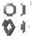
Figure 7 shows various views of an adaptor frame (or drilling riser support insert) according to the invention. -
Figure 8 illustrates the sequential steps used in transferring a drilling riser between adjacent wells on the seafloor in a method according to the invention. - The invention may best be understood by reference to one particular preferred embodiment whose apparatus is illustrated in
Figures 1 - 7 and an associated method of use is illustrated inFigure 8 as a sequence of steps. The drawing figures outline general equipment and methodology for drilling multiple wells from a floating unit, and the installation of production risers, while minimizing or eliminating the need to retrieve the drilling riser when moving between wells. - The system shown is intended for use on a well pattern which is essentially rectangular in shape, but it should be understood that similar methodology could be adapted to well patterns of a more square shape or other patterns.
- One particular feature of the system is a transfer trolley, which is suspended from the lower deck (the production deck) of the floating platform. The transfer trolley is set to run down the length of the well pattern. The position of the transfer trolley is held side to side by fixed rails, or similar, which may form part of the deck structure. The end-to-end position of the transfer trolley may be shifted using a rack-and-pinion arrangement with the pinion(s) turned by hydraulic motors or the like. The end-to-end position of the transfer trolley may be controlled by other means - for example by a pair of opposing winches used to translate the transfer trolley.
- The transfer trolley may be used to transport the assembled drilling riser together with an associated tensioner and blowout preventer (BOP) between well bay positions.
- The production deck (the lower deck) of the floating structure may contain discrete (separate)
tensioners 42 for the near-vertical production risers. These tensioners may be arranged in a regular geometric pattern, as shown inFigures 1 . It should be noted that the spacing of the well bay on the structure may be chosen to be consistent with the physical requirements to fit production tensioners, surface trees, connection jumpers, and other required equipment for drilling, production, work over and so forth. The wells may be spaced on the seafloor to provide access space as required for various seafloor activities related to drilling, production, etc. The seafloor and surface spacing may not necessarily be identical (due to different space requirements) but may be established in a way to minimize the offset angles between corresponding seafloor and surface locations. - Referring in particular to
Figures 1 and2 , the TLP includes provision for installation of a total of 27 riser tensioners in a 9-by-3 array ofwell slots 20 on the lower deck 82 of a TLP. The drilling riser is deployed only from the central of the three columns, with the ability to reach each of the 27 subsea well head locations from at least one of the nine positions within the central column. For certain well patterns, less than the full 9 central column positions may be needed to reach each of the wells on the seafloor. The central column may initially be open to allow translation of the hanging drilling riser to locations appropriate for reaching the well heads. Production risers in the two outer columns may be installed first, withtensioners 42 andsurface trees 40 mounted on the lower deck (production deck) 82. As additional risers are added, inserts may be placed in the central column to allow installation of production riser tensioners therein.Tree access platforms 16 may be provided inproduction deck structure 18.Figure 1 shows the outer columns with all production risers installed, a single production riser installed at one end of the central column, and thedrilling riser 36 near the midpoint of the central column.Figure 1 also shows a smaller BOP 28 (used for well completion) on a Production Riser Tensioner 42 (connected to production riser tension joint 44) in the outer row adjacent to thelarger drilling BOP 26, confirming adequate clearance between the two BOP's. -
Figure 2 shows the production deck 82 of a TLP equipped with a drilling riser transport system according to the invention viewed from the opposite end of the well bay as that shown inFigure 1 and with the topsides structure (drilling deck) in place. The twowinches 22 shown at the near end of the opening in the lower deck 82 are for thedrilling riser guidelines 24. This view also shows the routing of theproduction 10,annulus 14 and control jumpers 12 for each of the surface trees. These jumpers are routed outward on the two outer columns of wells. Theboxes 84 above the central (open) column represent the tie off locations for the central wells. Note that there is ample clearance for hook up of hard piping to thedrilling BOP 26. - The leftmost illustration in
Figure 3 is a side view of a drilling riser assembly comprising drilling riser tension joint 36, a drillingriser tensioner system 30 and a high-pressure blowout preventer (BOP) 26 supported in a drillingriser transfer system 32 according to the invention. - As shown in the uppermost view of
Figure 3 (a top plan view), the support inserts for both theproduction tensioners 42 anddrilling riser tensioner 32 may rest onbrackets 38 extending outward from themain beams 64 along the edges of the opening in the lower deck. Thedrilling riser 36 may be moved by means of atransporter 32 which fits around the Drilling Riser Transport (DRT)support insert 66 and can lift it clear of thesupport brackets 38. - Also shown in the top and side views of
Figure 3 arewinches 22 forguide wire ropes 24.Winches 22 may be constant tension winches.Guide wire rope 24 may be routed around sheave 86 and through openings indrilling riser tensioner 30 and hole 62 (seeFigure 6 ) intransport trolley 32. - As illustrated in
Figure 4 , thetransporter 32 may move the drilling riser assembly (26 + 30 + 36 inFigure 3 ) on rails 34 (Figure 1 ) by means of a rack-and-pinion drive system, located on the edges of the opening in the lower deck.Racks 70 may be attached to well bay support beams 64 and/or tracks 72 andpinions 68 may be mounted ontransport trolley 32 and connected tohydraulic drive motors 52. The transporter may be supported by Hilman rollers 54 (Hilman Inc., Marlboro, NJ 07746) resting onhorizontal tracks 72. As shown inFigure 4 , the drive system of the illustrated embodiment uses four drive motors. In addition, the motion of the transporter may be controlled by guide rollers (not shown) reacting on the sides of the track on one or both sides of the opening in the lower deck. - In
Figure 4 ,adaptor frame 66 is shown in the retracted position. The extended position of theadaptor frame 66 is shown in phantom in the lower left view ofFigure 4 . When in the retracted position, theadaptor frame 66 is supported bydeck support brackets 38 and not (to any significant degree) bytransport trolley 32. It will be appreciated that the retracted position ofadaptor frame 66 is that used during drilling operations. When in the retracted position, the reactive force of the drillingriser tensioner system 30 is transmitted to thedeck structure 64 viadeck support brackets 38. The supports of transport trolley 32 (e.g.,Hilman rollers 54 and support arms 88) are not exposed to the dynamic loads of heave compensation imposed bytensioner system 30. -
Figure 5 is similar toFigure 4 , but withadaptor frame 66 in the extended position. As shown inFigure 5 , theDRT support insert 66 may be lifted relative to thetransporter 32 by fourhydraulic cylinders 66, two on each side of the insert. The geometric shape of the support insert and the transporter may be such that overlap between the two parts provides guidance as the support insert rises, limiting lateral loads on the hydraulic cylinders. - Extending
adapter frame 66 results in lifting the drilling riser assembly sufficiently to clear the wellhead on the seafloor to which is was connected. This permits the drilling riser assembly to be moved horizontally within the well bay without disconnecting either thedrilling BOP 26 or the drillingriser tensioner system 30. Moreover, the drilling riser itself may remain in the sea. In certain embodiments, a dummy wellhead may be provided on the seafloor for landing and securing the lower end of the drilling riser while production risers are run. This can help to prevent collisions between the risers. -
Figure 6 contains four views of atransport trolley 32 according to one embodiment of the invention -- an isometric view, a top plan view, a side view and an end view. Adapterframe lift cylinders 60 are shown withintransport trolley 32. Also shown areopenings 62 forguidelines 24 which may be sized to also permit passage of the remote ROV guide post tops (seeFigure 8 ). -
Figure 7 contains four views of anadapter frame 66 according to one embodiment of the invention -- an isometric view, a top plan view, a side view and an end view.Adapter frame 66 has acentral opening 67 with aperimeter rim 74 which may project intoopening 67. Rim (or flange) 74 may be sized and configured to fit drillingriser tensioner system 30. Drillingriser tensioner system 30 is supported onrim 74. Load brackets 80 are sized and configured to engagedeck support brackets 38. Liftextensions 78 are sized and configured to engage adapterframe lift cylinders 60. In a system according to the invention, the static load of the drilling riser assembly is borne onlift extensions 78 whentransport trolley 32 is moved horizontally but the static and dynamic loads are borne by load extensions 80 when the drilling riser is connected and tensioned bytensioner system 30. As shown inFigure 7 , load extensions 80 may be reinforced withgussets 90. - Specific design parameters for one particular preferred embodiment of a drilling riser transport system according to the invention are:
- The
transporter 32 may be supported by four sets ofHillman rollers 54. - The top of the
DRT support insert 66 is level with the top of the support rails when thetransporter lift cylinders 60 are retracted. - The
DRT 30 fits within theinner opening 67 of thesupport insert 66, and is supported by aledge 74 around the perimeter of the opening. - Lift of the
DRT support insert 66 relative to thetransporter 32 is sufficient to clear the well head and its associated guide posts. - Maximum load carried by the
DRT support insert 66 is carried through the brackets 80. - Static load only is carried by the
transporter 32 during lift and movement of the drilling riser. - The
transporter 32 carries no load when the DRT support insert 66is resting on the brackets 80. - The transporter may be driven by a
rack 70 andpinion 68 system powered byhydraulic drive motors 52. - As shown in the sequence illustrated in
Figure 8 , the transfer method according to the invention begins at Step 1 with the drilling riser and its associated tieback connector attached to a home position wellhead. At Step 2, the guidelines are slackened so that the ROV can unlock the upper section of the guideposts ("guide post tops") and move them to the adjacent wellhead. If not already deployed, the guide arms may be folded down (using the ROV) and the guidelines reattached to the drilling riser by positioning the guidelines in the lower guide arms via gates in the guide arms. In Step 3, the tieback is disconnected from the home position wellhead and lifted by extending the adapterframe lift cylinders 60. This provides sufficient clearance to move the tieback connector from the home position wellhead to the adjacent wellhead by applying a selected amount of tension to theguidelines 24 using guide line winches 22 (which may be constant tension winches). Thetransporter 32 may concurrently move the drilling riser to the closest available drilling position over the target wellhead. The lower guide arms may be free to swivel around the tie back connector to align and connect with the guidelines and guideposts. The guide arms may be sized such that, in the folded position, they may pass through passageways in the drilling riser tensioner andopenings 67 in drillingriser transfer trolley 32. After full positioning tension is applied to the guidelines thereby realigning the tieback connector over the adjacent well (Step 4), the drilling riser may be lowered (Step 5) by retractinghydraulic lift cylinders 60, and the tie back connector landed and locked on the adjacent wellhead. - Although particular embodiments of the present invention have been shown and described, they are not intended to limit what this patent covers. One skilled in the art will understand that various changes and modifications may be made without departing from the scope of the present invention as literally and equivalently covered by the following claims.
Claims (18)
- A tension leg platform comprising:a deck structure of a drilling deck for supporting topsides equipment and a production deck equipped with a well bay;an upper surface on the production deck and an undersurface on the production deck and a through opening in the production deck from the upper surface to the undersurface;the production deck further comprising a drilling riser assembly that comprises a drilling tensioning joint (36), a drilling riser tensioner system (30) and a high-pressure blowout preventer (26), the drilling riser assembly being supported in a drilling riser transfer system,wherein the driller riser assembly comprises a transporter adapted for translational movement within the through opening along a length of the well bay,the production deck is situated below the drilling deck in the deck structure, anda position of the transporter is held side-to-side by fixed rails forming a part of the deck structure.
- The tension leg platform according to claim 1, wherein the transporter with the drilling riser tensioner system (30) and the high-pressure blowout preventer (26) is configured to be translationally moved within the through opening without removing the drilling riser together with the drilling riser tensioner system (30) and the high-pressure blowout preventer (26) from the well bay or without disconnecting either the high-pressure blowout preventer or the drilling riser tensioner system.
- The tension leg platform according to claim 1, wherein the production deck is placed below the drilling deck with a clearance sufficient to allow the transporter with the drilling riser tensioner system (30) and the high-pressure blowout preventer (26) to be translationally moved within the through opening.
- The tension leg platform according to claim 1, wherein the transporter comprises an adapter frame moveable from a first position in which a load on the adapter frame is borne by the drilling riser transfer system to a second position wherein a load on the adapter frame is substantially borne by the deck support structure and not by the drilling riser transfer system.
- The tension leg platform according to claim 4, further comprising a drilling riser having a first end and an opposing second end supported by the adapter frame.
- The tension leg platform according to claim 4 or 5, wherein the drilling riser tensioner is attached to the drilling riser and the adapter frame.
- The tension leg platform according to claim 2, further comprising rollers on the transporter.
- The tension leg platform according to claim 7, wherein the rollers are non-motorized, load-carrying devices.
- The tension leg platform according to claim 7, further comprising a pair of tracks on opposing sides of the through opening in the deck sized and spaced to engage the rollers on the transporter.
- The tension leg platform according to any of the preceding claims, further comprising a rack on the production deck proximate the opening and a motor-driven pinion on the transporter sized and spaced to engage the rack.
- The tension leg platform according to claim 4, 5 or 6, further comprising hydraulic cylinders on the transporter operable to move the adapter frame from the first position to the second position.
- The tension leg platform according to claim 4, 5 or 6, further comprising projecting load extensions on the adapter frame sized and spaced to engage the deck support structure when the adapter frame is in the second position.
- The tension leg platform according to claim 12, further comprising support brackets connected to the deck support structure and projecting into the opening such that the load extensions on the adapter frame rest on the support brackets when the adapter frame is in the second position.
- The tension leg platform according to claim 4, 5 or 6, wherein the first position, wherein a load on the adapter frame is borne by the transporter, is elevated relative to the second position, wherein a load on the adapter frame is substantially borne by the deck support structure and not by the transporter.
- The tension leg platform according to claim 11, further comprising projecting lift extensions on the adapter frame sized and spaced to engage the hydraulic cylinders.
- The tension leg platform according to any of the preceding claims, further comprising:a pair of openings in the transporter;at least two guide lines each passing through one of the openings in the transporter;at least two winches connected to the deck support structure and engaged with a guide line; and,a pair of sheaves mounted on the adapter frame and in contact with the guide lines.
- The tension leg platform according to claim 16, wherein the guide lines are connected to a drilling riser supported by the adapter frame.
- A drilling riser transport system for a tension leg platform according to any one of the preceding claims, the drilling riser transport system comprising:a support structure;a transport trolley adapted for translational movement on the support structure;and,an adapter frame attached to the transport trolley and moveable from a first position wherein a drilling riser connected to the adapter frame is supported by the transport trolley to a second position wherein the drilling riser is supported by the support structure and not by the transport trolley.
Applications Claiming Priority (4)
| Application Number | Priority Date | Filing Date | Title |
|---|---|---|---|
| US201161543663P | 2011-10-05 | 2011-10-05 | |
| US201261606031P | 2012-03-02 | 2012-03-02 | |
| US201261610805P | 2012-03-14 | 2012-03-14 | |
| EP12844498.1A EP2769045B1 (en) | 2011-10-05 | 2012-10-05 | Method and apparatus for drilling multiple subsea wells from an offshore platform at a single site |
Related Parent Applications (2)
| Application Number | Title | Priority Date | Filing Date |
|---|---|---|---|
| EP12844498.1A Division EP2769045B1 (en) | 2011-10-05 | 2012-10-05 | Method and apparatus for drilling multiple subsea wells from an offshore platform at a single site |
| EP12844498.1A Division-Into EP2769045B1 (en) | 2011-10-05 | 2012-10-05 | Method and apparatus for drilling multiple subsea wells from an offshore platform at a single site |
Publications (2)
| Publication Number | Publication Date |
|---|---|
| EP2995547A2 true EP2995547A2 (en) | 2016-03-16 |
| EP2995547A3 EP2995547A3 (en) | 2016-10-05 |
Family
ID=48135028
Family Applications (2)
| Application Number | Title | Priority Date | Filing Date |
|---|---|---|---|
| EP15191275.5A Withdrawn EP2995547A3 (en) | 2011-10-05 | 2012-10-05 | Method and apparatus for drilling multiple subsea wells from an offshore platform at a single site |
| EP12844498.1A Active EP2769045B1 (en) | 2011-10-05 | 2012-10-05 | Method and apparatus for drilling multiple subsea wells from an offshore platform at a single site |
Family Applications After (1)
| Application Number | Title | Priority Date | Filing Date |
|---|---|---|---|
| EP12844498.1A Active EP2769045B1 (en) | 2011-10-05 | 2012-10-05 | Method and apparatus for drilling multiple subsea wells from an offshore platform at a single site |
Country Status (7)
| Country | Link |
|---|---|
| US (4) | US9238943B2 (en) |
| EP (2) | EP2995547A3 (en) |
| KR (4) | KR101735901B1 (en) |
| CN (2) | CN107654192B (en) |
| GB (1) | GB2506761A (en) |
| SG (2) | SG11201401714UA (en) |
| WO (1) | WO2013062736A1 (en) |
Families Citing this family (19)
| Publication number | Priority date | Publication date | Assignee | Title |
|---|---|---|---|---|
| SG11201401714UA (en) * | 2011-10-05 | 2014-09-26 | Seahorse Equip Corp | Method and apparatus for drilling multiple subsea wells from an offshore platform at a single site |
| WO2013057166A2 (en) | 2011-10-18 | 2013-04-25 | Total Sa | A floating offshore facility and a method for drilling a well |
| US9352808B2 (en) | 2012-01-16 | 2016-05-31 | Seahorse Equipment Corp | Offshore platform having SCR porches mounted on riser keel guide |
| US9464488B2 (en) * | 2013-09-30 | 2016-10-11 | National Oilwell Varco, L.P. | Performing simultaneous operations on multiple wellbore locations using a single mobile drilling rig |
| CN103590763B (en) * | 2013-11-23 | 2015-07-29 | 湖北江汉建筑工程机械有限公司 | A kind of oil drilling platform preventer transport erecting device |
| US20190194895A1 (en) * | 2015-10-29 | 2019-06-27 | Maersk Drilling A/S | Methods and apparatus for forming an offshore well |
| WO2017071707A1 (en) * | 2015-10-29 | 2017-05-04 | Maersk Drilling A/S | Offshore drilling and a configurable support structure for the same |
| US9670732B1 (en) * | 2016-01-14 | 2017-06-06 | Chevron U.S.A. Inc. | Batch drilling using multiple mudline closure devices |
| CN105857519A (en) * | 2016-03-22 | 2016-08-17 | 浙江海洋学院 | Four-anchor positioning system of engineering ship |
| NO20160906A1 (en) | 2016-05-26 | 2017-10-30 | Sembcorp Marine Integrated Yard Pte Ltd | Sea bed terminal for drilling |
| US9976364B2 (en) | 2016-09-07 | 2018-05-22 | Frontier Deepwater Appraisal Solutions LLC | Floating oil and gas facility with a movable wellbay assembly |
| CN106639917A (en) * | 2017-03-16 | 2017-05-10 | 上海振华重工(集团)股份有限公司 | Sleeve tensioner moving system and sleeve tensioning system |
| CN106882727A (en) * | 2017-03-16 | 2017-06-23 | 上海振华重工(集团)股份有限公司 | Slide plate containing box jacking system and sleeve pipe clamping system |
| GB2560931B (en) * | 2017-03-28 | 2023-01-11 | Equinor Energy As | Connector |
| GB2568740B (en) * | 2017-11-27 | 2020-04-22 | Equinor Energy As | Wellhead load relief device |
| NL2020273B1 (en) * | 2018-01-12 | 2019-07-18 | Itrec Bv | Drilling vessel |
| US10612315B2 (en) * | 2018-02-08 | 2020-04-07 | Saudi Arabian Oil Company | Smart skidding system for land operations |
| WO2022067410A1 (en) * | 2020-10-02 | 2022-04-07 | Petróleo Brasileiro S.A. - Petrobras | Polyvalent riser balcony |
| CN113187443B (en) * | 2021-04-30 | 2022-10-25 | 刘刚 | Drilling equipment and method for stratum containing shallow gas or natural gas hydrate area |
Family Cites Families (44)
| Publication number | Priority date | Publication date | Assignee | Title |
|---|---|---|---|---|
| US3474629A (en) * | 1967-12-08 | 1969-10-28 | Shell Oil Co | Rotatable drilling platform |
| US3502143A (en) | 1968-05-29 | 1970-03-24 | Shell Oil Co | Marine riser support system |
| ES435704A1 (en) * | 1974-03-18 | 1977-02-01 | Finn Tveten & So Ans Y Ans Ake | Parking device for blowout preventer |
| US4108318A (en) * | 1974-06-07 | 1978-08-22 | Sedco, Inc. Of Dallas, Texas | Apparatus for offshore handling and running of a BOP stack |
| GB2046330B (en) * | 1979-02-15 | 1982-10-27 | British National Oil Corp | Apparatus for use in placing a submarine structure on the sea bed alongside an underwater well and method of drilling a plurality of closely spaced underwater wells |
| US4625806A (en) * | 1979-09-26 | 1986-12-02 | Chevron Research Company | Subsea drilling and production system for use at a multiwell site |
| US4324077A (en) * | 1979-10-26 | 1982-04-13 | Lee C. Moore Corporation | Method of moving a drilling rig long and short distances |
| US4305468A (en) * | 1980-05-05 | 1981-12-15 | Conoco Inc. | Method for drilling wellbores from an offshore platform |
| US4367796A (en) * | 1980-11-21 | 1983-01-11 | Global Marine, Inc. | Blowout preventer and guideline handling |
| US4435108A (en) * | 1981-08-11 | 1984-03-06 | Sedco, Inc. | Method of installing sub-sea templates |
| FI64919B (en) * | 1982-06-15 | 1983-10-31 | Waertsilae Oy Ab | FLYTANDE BORRNINGSPLATTFORM |
| US4624318A (en) * | 1983-05-26 | 1986-11-25 | Chevron Research Company | Method and means for storing a marine riser |
| US4557332A (en) * | 1984-04-09 | 1985-12-10 | Shell Offshore Inc. | Drilling riser locking apparatus and method |
| US4702320A (en) | 1986-07-31 | 1987-10-27 | Otis Engineering Corporation | Method and system for attaching and removing equipment from a wellhead |
| FR2607773B1 (en) * | 1986-12-03 | 1989-03-31 | Sedco Forex Sa Services Techni | SEMI-SUBMERSIBLE CATAMARAN-TYPE PLATFORM FOR DRILLING AT SEA |
| US5150987A (en) * | 1991-05-02 | 1992-09-29 | Conoco Inc. | Method for installing riser/tendon for heave-restrained platform |
| US5492436A (en) * | 1994-04-14 | 1996-02-20 | Pool Company | Apparatus and method for moving rig structures |
| GB2315083A (en) | 1996-07-11 | 1998-01-21 | Philip Head | Accessing sub sea oil well |
| NO309134B1 (en) * | 1997-01-07 | 2000-12-18 | Lund Mohr & Giaever Enger Mari | Hull construction for one-hull vessels |
| NO980987D0 (en) * | 1997-12-11 | 1998-03-06 | Ormen Brede As | Drilling and production vessels |
| NL1010884C2 (en) * | 1998-12-23 | 2000-06-26 | Hans Van Der Poel | Work ship. |
| US6691784B1 (en) * | 1999-08-31 | 2004-02-17 | Kvaerner Oil & Gas A.S. | Riser tensioning system |
| GB2358032B (en) * | 2000-01-05 | 2002-03-27 | Sedco Forex Internat Inc | Method and apparatus for drillig subsea wells |
| US6554075B2 (en) | 2000-12-15 | 2003-04-29 | Halliburton Energy Services, Inc. | CT drilling rig |
| FR2826051B1 (en) * | 2001-06-15 | 2003-09-19 | Bouygues Offshore | GROUND-SURFACE CONNECTION INSTALLATION OF A SUBSEA PIPE CONNECTED TO A RISER BY AT LEAST ONE FLEXIBLE PIPE ELEMENT HOLDED BY A BASE |
| US6672390B2 (en) | 2001-06-15 | 2004-01-06 | Shell Oil Company | Systems and methods for constructing subsea production wells |
| FR2841293B1 (en) | 2002-06-19 | 2006-03-03 | Bouygues Offshore | TELESCOPIC GUIDE FOR DRILLING AT SEA |
| US20040052586A1 (en) | 2002-08-07 | 2004-03-18 | Deepwater Technology, Inc. | Offshore platform with vertically-restrained buoy and well deck |
| US7032673B2 (en) | 2002-11-12 | 2006-04-25 | Vetco Gray Inc. | Orientation system for a subsea well |
| NO20025858D0 (en) * | 2002-12-06 | 2002-12-06 | Maritime Hydraulics As | Horizontal force equalized riser pull device |
| WO2005042914A1 (en) * | 2003-10-29 | 2005-05-12 | Saudi Arabian Oil Company | Blow out preventer transfer platform |
| US7021402B2 (en) * | 2003-12-15 | 2006-04-04 | Itrec B.V. | Method for using a multipurpose unit with multipurpose tower and a surface blow out preventer |
| SE530900C2 (en) * | 2007-04-02 | 2008-10-14 | Gva Consultants Ab | drilling device |
| US9062500B2 (en) * | 2007-07-20 | 2015-06-23 | Schlumberger Technology Corporation | System and method to facilitate interventions from an offshore platform |
| KR101594854B1 (en) * | 2008-02-15 | 2016-02-18 | 아이티알이씨 비. 브이. | Offshore drilling vessel |
| US8522880B2 (en) * | 2008-04-29 | 2013-09-03 | Itrec B.V. | Floating offshore structure for hydrocarbon production |
| US20100135728A1 (en) * | 2008-05-14 | 2010-06-03 | Kingtime Interanational Limited | Mobile offshore drilling and production platform |
| US8573308B2 (en) * | 2008-09-09 | 2013-11-05 | Bp Corporation North America Inc. | Riser centralizer system (RCS) |
| EP2186993B1 (en) * | 2008-11-17 | 2019-06-26 | Saipem S.p.A. | Vessel for operating on underwater wells and working method of said vessel |
| MY167555A (en) * | 2009-10-09 | 2018-09-14 | Bumi Armada Berhad | External turret with above water connection point |
| WO2012032104A2 (en) * | 2010-09-09 | 2012-03-15 | Aker Mh As | A seafastening apparatus for a tensioner assembly |
| BR112013007844A2 (en) | 2010-10-01 | 2016-06-07 | Aker Subsea Inc | slack-tied hull float riser system |
| SG11201401714UA (en) * | 2011-10-05 | 2014-09-26 | Seahorse Equip Corp | Method and apparatus for drilling multiple subsea wells from an offshore platform at a single site |
| WO2013057166A2 (en) | 2011-10-18 | 2013-04-25 | Total Sa | A floating offshore facility and a method for drilling a well |
-
2012
- 2012-10-05 SG SG11201401714UA patent/SG11201401714UA/en unknown
- 2012-10-05 EP EP15191275.5A patent/EP2995547A3/en not_active Withdrawn
- 2012-10-05 KR KR1020147027573A patent/KR101735901B1/en active Active
- 2012-10-05 KR KR1020137030746A patent/KR101600155B1/en active Active
- 2012-10-05 KR KR1020157030628A patent/KR101709035B1/en active Active
- 2012-10-05 EP EP12844498.1A patent/EP2769045B1/en active Active
- 2012-10-05 WO PCT/US2012/059058 patent/WO2013062736A1/en not_active Ceased
- 2012-10-05 GB GB1317868.6A patent/GB2506761A/en not_active Withdrawn
- 2012-10-05 SG SG10201602165RA patent/SG10201602165RA/en unknown
- 2012-10-05 CN CN201711035434.5A patent/CN107654192B/en active Active
- 2012-10-05 KR KR1020167014387A patent/KR101964783B1/en active Active
- 2012-10-05 US US13/646,277 patent/US9238943B2/en active Active
- 2012-10-05 CN CN201280059810.3A patent/CN104136704B/en active Active
-
2015
- 2015-10-21 US US14/919,486 patent/US9458671B2/en active Active
-
2016
- 2016-09-09 US US15/260,900 patent/US9677368B2/en active Active
-
2017
- 2017-05-19 US US15/600,107 patent/US9988848B2/en active Active
Non-Patent Citations (1)
| Title |
|---|
| None |
Also Published As
| Publication number | Publication date |
|---|---|
| KR20130138853A (en) | 2013-12-19 |
| EP2769045A1 (en) | 2014-08-27 |
| US9677368B2 (en) | 2017-06-13 |
| US20160376862A1 (en) | 2016-12-29 |
| WO2013062736A1 (en) | 2013-05-02 |
| US9988848B2 (en) | 2018-06-05 |
| KR101735901B1 (en) | 2017-05-15 |
| EP2769045A4 (en) | 2016-11-16 |
| EP2995547A3 (en) | 2016-10-05 |
| US20160145943A1 (en) | 2016-05-26 |
| GB2506761A (en) | 2014-04-09 |
| KR101964783B1 (en) | 2019-04-02 |
| GB201317868D0 (en) | 2013-11-20 |
| CN104136704B (en) | 2017-12-19 |
| CN104136704A (en) | 2014-11-05 |
| KR20160067196A (en) | 2016-06-13 |
| CN107654192B (en) | 2020-02-18 |
| EP2769045B1 (en) | 2019-11-06 |
| US20170298694A1 (en) | 2017-10-19 |
| KR20150123975A (en) | 2015-11-04 |
| KR101709035B1 (en) | 2017-02-21 |
| KR101600155B1 (en) | 2016-03-04 |
| KR20140129352A (en) | 2014-11-06 |
| SG11201401714UA (en) | 2014-09-26 |
| SG10201602165RA (en) | 2016-04-28 |
| US20130098627A1 (en) | 2013-04-25 |
| CN107654192A (en) | 2018-02-02 |
| US9238943B2 (en) | 2016-01-19 |
| US9458671B2 (en) | 2016-10-04 |
Similar Documents
| Publication | Publication Date | Title |
|---|---|---|
| US9988848B2 (en) | Method and apparatus for drilling multiple subsea wells from an offshore platform at a single site | |
| US11781384B2 (en) | Drilling installation: handling system, method for independent operations | |
| CN110077538B (en) | Offshore drilling system, vessel and method | |
| US9714546B2 (en) | Offshore drilling rig and a method of operating the same | |
| US9266586B2 (en) | Offshore vessel and method of operation of such an offshore vessel | |
| CN111491857B (en) | Vessel and method for performing subsea wellbore related activities | |
| WO2005059297A2 (en) | Method of using a multipurpose unit with multipurpose tower and a surface blow out preventer | |
| WO2017050336A1 (en) | Offshore drilling vessel | |
| EP3755618B1 (en) | Vessel and method for performing subsea wellbore related activities, e.g. workover activities, well maintenance, installing an object on a subsea well bore | |
| CN118306513A (en) | Semi-submersible drilling vessel for use in, for example, harsh environments | |
| EP3829967B1 (en) | Semi-submersible |
Legal Events
| Date | Code | Title | Description |
|---|---|---|---|
| PUAI | Public reference made under article 153(3) epc to a published international application that has entered the european phase |
Free format text: ORIGINAL CODE: 0009012 |
|
| 17P | Request for examination filed |
Effective date: 20151023 |
|
| AC | Divisional application: reference to earlier application |
Ref document number: 2769045 Country of ref document: EP Kind code of ref document: P |
|
| AK | Designated contracting states |
Kind code of ref document: A2 Designated state(s): AL AT BE BG CH CY CZ DE DK EE ES FI FR GB GR HR HU IE IS IT LI LT LU LV MC MK MT NL NO PL PT RO RS SE SI SK SM TR |
|
| RIC1 | Information provided on ipc code assigned before grant |
Ipc: B63B 21/50 20060101AFI20160502BHEP |
|
| PUAL | Search report despatched |
Free format text: ORIGINAL CODE: 0009013 |
|
| AK | Designated contracting states |
Kind code of ref document: A3 Designated state(s): AL AT BE BG CH CY CZ DE DK EE ES FI FR GB GR HR HU IE IS IT LI LT LU LV MC MK MT NL NO PL PT RO RS SE SI SK SM TR |
|
| RIC1 | Information provided on ipc code assigned before grant |
Ipc: B63B 21/50 20060101AFI20160826BHEP |
|
| RAP1 | Party data changed (applicant data changed or rights of an application transferred) |
Owner name: SINGLE BUOY MOORINGS INC. |
|
| 17Q | First examination report despatched |
Effective date: 20171213 |
|
| STAA | Information on the status of an ep patent application or granted ep patent |
Free format text: STATUS: THE APPLICATION HAS BEEN WITHDRAWN |
|
| 18W | Application withdrawn |
Effective date: 20201027 |