EP2995503A1 - A roof box - Google Patents
A roof box Download PDFInfo
- Publication number
- EP2995503A1 EP2995503A1 EP15185049.2A EP15185049A EP2995503A1 EP 2995503 A1 EP2995503 A1 EP 2995503A1 EP 15185049 A EP15185049 A EP 15185049A EP 2995503 A1 EP2995503 A1 EP 2995503A1
- Authority
- EP
- European Patent Office
- Prior art keywords
- box
- conduit
- cover
- internal volume
- inlet
- Prior art date
- Legal status (The legal status is an assumption and is not a legal conclusion. Google has not performed a legal analysis and makes no representation as to the accuracy of the status listed.)
- Granted
Links
Images


Classifications
-
- B—PERFORMING OPERATIONS; TRANSPORTING
- B60—VEHICLES IN GENERAL
- B60R—VEHICLES, VEHICLE FITTINGS, OR VEHICLE PARTS, NOT OTHERWISE PROVIDED FOR
- B60R9/00—Supplementary fittings on vehicle exterior for carrying loads, e.g. luggage, sports gear or the like
- B60R9/04—Carriers associated with vehicle roof
- B60R9/055—Enclosure-type carriers, e.g. containers, boxes
Definitions
- the invention has for an object a roof box (or "trunk"). Boxes are known for the carriage of luggage and items in general, which are intended to be mounted on the roof of a motor vehicle, in particular of a car, for example by means of typical roof bars.
- Boxes of this kind define an isolated loading space, wherein the baggage can be housed and protected from wind and weather, dust and staining substances in general.
- the luggage can be stowed on the vehicle in an easy and rapid manner, without the need to necessarily handle straps, cables or elastic nets, and the like.
- Roof boxes include a tub-shaped base body and a cover for closing the base body, wherein said isolated space is defined.
- roof boxes were realized which exhibit an aerodynamics conformation and different systems were devised for closing the cover on the base body.
- the technical task at the base of the present invention is therefore to provide a roof box which overcomes the drawback exhibited by the prior art of unwanted opening of the cover.
- the box 1 herein provided finds application within the field described in the discussion on the prior art and can therefore be mounted on the roof of motor vehicles for the carriage of luggage and items in general, e.g. by means of bars of the known type.
- the box 1 which may exhibit an elongated shape, firstly comprises a bottom base body 11 and an upper cover 12 for closing the base body 11. Once the box 1 is closed, an isolated internal volume V, wherein the items can be housed, comes to be defined therein - i.e. therein contained and thus isolated from the outside of the box.
- this volume is "empty", which means that it is suitable for receiving the items to be carried.
- the base body 11 is generally tub-shaped and with an internal concave side, while the cover 12 exhibits a convex shape and is in turn provided with an internal concave side, which is substantially arch-shaped.
- the base body 11 and the cover 12 may for example be made of plastic or any other materials suitable for the purpose.
- the box 1 is disposed axially to the vehicle, i.e., with the length thereof being parallel to the axis of the vehicle.
- the box 1 exhibits a front part 10 intended to be facing towards the front travel direction of the vehicle whereon it is fitted, and a rear opposite part.
- the box 1 is subject to air resistance, starting from the front side 10 or "face" of the box 1.
- the box 1 includes at least one Venturi effect device 2 which is able to put the outside of the box in communication with said internal volume V, so as to produce a depression therein.
- the Venturi effect device 2 (hereinafter the "Venturi device"), causes a decrease in pressure within the internal volume V of the box 1.
- the box 1 herein provided can be identified as a roof box also of the known type, to which the Venturi device 2 of the invention is coupled.
- the Venturi device 2 is preferably mounted on the cover 12, for example relative to the axial plane of the box 1.
- the Venturi device 2 can be placed centrally to the cover 12; preferably, it is placed at the major height area of the box itself.
- the Venturi device 2 comprises at least a first conduit 20 with a variable section, arranged above the cover 12 and adapted to receive an air flow produced during the running of the vehicle.
- the conduit is thus arranged at the outer surface of the cover 12 and is preferably oriented axially thereto (i.e. it exhibits a longitudinal parallel axis), so as to intercept said air flow effectively.
- the Venturi device 2 may include an external elongated element 21, for example, a generally plate-like element, which is laterally provided with transversal sidewalls in contact with the external surface of the cover 12, so as to define therewith the first conduit 20 (see Figures 1 and 1 a) .
- an external elongated element 21 for example, a generally plate-like element, which is laterally provided with transversal sidewalls in contact with the external surface of the cover 12, so as to define therewith the first conduit 20 (see Figures 1 and 1 a) .
- the external element 21 may be tile-shaped, specifically it may appear at least partially arched in the transverse direction, thereby forming a convexity.
- the external element 21 can be realized in a single piece, for example in plastic material.
- the external element 21 may exhibit substantially C-shaped cross-sections due the presence of the longitudinal sidewalls protruding downwards and contacting the external surface of the cover 12 with the lower free edges thereof.
- the internal section can be C-shaped, while the shape of the external surface, and thus its cross section profile, can be of a different type.
- the aforementioned first conduit 20 (see Figure 1 a) , is defined between the upper surface of the cover 12, covered by the external element 21, the ceiling of said element 21 and its sidewalls forming the sides thereof. It goes without saying that the shape of the lower edge of the sidewalls depends on the development of the external surface of the cover 12; the conduit is preferably open at its longitudinal ends 24, 25 and closed laterally by the sidewalls of the external element 21.
- the conduit has an inlet 24 for the air flow and an outlet 25 opposite the inlet.
- the external element 21 is preferably arranged with the length thereof disposed axially to the cover 12, so that the air flow may be effectively channeled into the first conduit 20.
- the external element 21 has a shape tapered in width, at least along a portion of its longitudinal extension.
- the width of such portion of the external element 21 decreases in a rear direction, i.e. in the direction of the back side of the box 1 (see figure 3 ).
- the external element 21 preferably includes a first front end 22 (relative to the orientation of the box 1), wherein it exhibits the major width thereof, thereby defining a passage for the inlet of air flow.
- the width of the external element 21 becomes narrower at least along a longitudinal portion, substantially up to a median zone and it may possibly, but not necessarily, widen along a next portion which comprises the rear end 23.
- the reduced section portion ST of the first conduit 20 may be defined by the presence of an obstructive element 31, whose additional features are more fully described here below, which obstructive element 31 is placed internally the first conduit 20, thereby defining a reduced light portion.
- the above-mentioned first conduit 20 includes at least one longitudinal portion with reduced cross-section ST, thereby defining a narrowing for the passage of the channeled air flow.
- this reduced section portion ST may exhibit a variable and non-constant section, and that in other words, it is a longitudinal portion along which the amplitude of the light of the conduit decreases.
- the conduit Upstream of this reduced section portion ST (or second portion), the conduit includes a portion with a larger section PT (or first portion), with a funnel-like development preferably tapered inwardly.
- upstream is defined in relation to the air flow direction.
- reduced section portion ST By the term “reduced section portion ST” herein utilized, it is meant that the section of this portion is smaller than that of a different portion of the conduit and vice versa with reference to the portion with larger section PT.
- the second portion ST is narrower than the first portion PT arranged upstream.
- Such length portions of the first conduit 20 do not necessarily exhibit a different thickness, i.e., the vertical dimensions thereof may not differ significantly from one another.
- the second portion ST may be thinner.
- the first and second PT, ST portions can be positioned relative thereto, as shown schematically in Figure 3 .
- the Venturi device 2 of the invention includes a communication path P between the internal volume V of the box 1 and a suction portion of the first conduit 20 which includes (or corresponds) to the already mentioned reduced section portion ST. Therefore, the path P starts from inside the box 1 (i.e. from the inner side of the cover 12), and then reaches the portion of the Venturi device 2 where pressure's decrease is generated.
- the air flows outside, through the rear inlet 25 of the first conduit 20 by passing through the rear end 23 of the external element 21.
- air suction from the inside of the box 1, may also help to decrease internal temperature.
- the Venturi device 2 includes an internal element 31, 32, comprising a second conduit 35, 36, 37, wherein said communication path P is defined, which extends between a first inlet 33 located within said internal volume V, and a second inlet 34 arranged in said suction portion (see Figure 5 ).
- This internal element 31, 32 is placed relative to a through hole 120 formed on the cover 12 of the box 1 (see figure 2 ).
- this internal element 31, 32 may comprise a first member 31, which is preferably a sleeve closed at the top and open at the bottom thereof, and realized, by way of example, in a single piece with the external element 21, which may identify aforementioned obstructive element that helps to decrease reduction in the amount of light of the main conduit (see Figures 2 and 3 ).
- the second inlet 34 of the second conduit may be defined by a through hole 37 formed transversely to the walls of the first member 31.
- a through hole 37 is facing toward the rear of the Venturi device 2 (and therefore of the box 1), i.e., towards the outlet 25 of the first conduit 20 (as shown in Figures 4 and 5 ).
- the aforementioned second inlet 34 may be located in the reduced section portion ST of the first conduit 20, or also downstream thereof, where pressure is however lower than that in the larger section portion located upstream.
- a second member 32 can be associated to the first member 31, for example via a rotatable coupling, according to the configuration shown in Figure 5 .
- Such second member 32 is provided for allowing alternately opening and obstruction of the communication path P between the internal volume V and the first conduit 20, on user's command.
- the second member 32 may conform a shutter 320, shown in Figure 2 as a wall with cylindrical development, which is so dimensioned as to be able to completely close the through hole of the first member 31; the shutter 320 is further suitable for being moved, by way of example, along a cylindrical surface, so as to allow passage of air.
- the user may decide whether to operate the depression effect of the inventive device 2, if need be.
- prongs 38 being inferiorly formed in the second member 32 and easily accessible when the cover 12 is open.
- the second member 32 has preferably a through hole 35 which is coaxial, or otherwise in communication with the internal space 36 of the first member 31.
- first inlet 33 of the second conduit 35, 36, 37 is defined by the through hole of the second member 32.
- suitable sealing means may be provided, which are for example realized by means of a ring 41 provided with an annular seat so as to accommodate an O-ring 42, which is so positioned as to circumscribe the internal element 31, 32, preferably on the upper side of the cover 12.
- Removable fastening means such as screw means, may be provided for easy assembly (and disassembly) of the Venturi device 2 herein described.
- aforesaid external element 21 may conform inferiorly one or more tangs 51 being internally threaded and arranged coaxial to small through holes 52 formed within the cover 12, wherein fixing screws 53 can be inserted, as shown by way of example in Figure 2 .
Landscapes
- Engineering & Computer Science (AREA)
- Mechanical Engineering (AREA)
- Body Structure For Vehicles (AREA)
- Fittings On The Vehicle Exterior For Carrying Loads, And Devices For Holding Or Mounting Articles (AREA)
Abstract
Description
- The invention has for an object a roof box (or "trunk"). Boxes are known for the carriage of luggage and items in general, which are intended to be mounted on the roof of a motor vehicle, in particular of a car, for example by means of typical roof bars.
- Boxes of this kind define an isolated loading space, wherein the baggage can be housed and protected from wind and weather, dust and staining substances in general.
- Further, owing to roof boxes, the luggage can be stowed on the vehicle in an easy and rapid manner, without the need to necessarily handle straps, cables or elastic nets, and the like.
- Roof boxes include a tub-shaped base body and a cover for closing the base body, wherein said isolated space is defined.
- One of the drawbacks exhibited by the roof boxes of the known type, is that its cover tends to open due to air resistance when the car is driven at high speed.
- In order to obviate this drawback, roof boxes were realized which exhibit an aerodynamics conformation and different systems were devised for closing the cover on the base body.
- However such measures turned out to be not fully resolutive for practical purposes.
- The technical task at the base of the present invention, is therefore to provide a roof box which overcomes the drawback exhibited by the prior art of unwanted opening of the cover.
- The technical task mentioned is attained by the roof box realized according to claim 1.
- Further characteristics and advantages of the present invention will become more apparent from the indicative, and therefore non-limiting, description of a preferred but non-exclusive embodiment of the roof box, as illustrated in the accompanying drawings wherein:
-
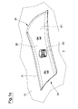
Figure 1 is an axonometric view of the box of the invention; -
Figure 1 a is an enlarged view of the particular K of the preceding figure. -
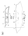
Figure 2 is an exploded axonometric view of a Venturi effect device included in the invention; -
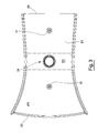
Figure 3 is a bottom view of an external element comprised within the device of the preceding figure; and -
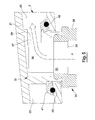
Figure 4 is an axonometric view of the external element of the preceding figure; and -
Figure 5 is a detail of a longitudinal sectional view of the roof box of the invention. - With reference to the above mentioned figures, by 1 it is indicated the roof box (or "trunk") according to the invention.
- The box 1 herein provided, finds application within the field described in the discussion on the prior art and can therefore be mounted on the roof of motor vehicles for the carriage of luggage and items in general, e.g. by means of bars of the known type.
- The box 1, which may exhibit an elongated shape, firstly comprises a
bottom base body 11 and anupper cover 12 for closing thebase body 11. Once the box 1 is closed, an isolated internal volume V, wherein the items can be housed, comes to be defined therein - i.e. therein contained and thus isolated from the outside of the box. - Accordingly, this volume is "empty", which means that it is suitable for receiving the items to be carried.
- The
base body 11 is generally tub-shaped and with an internal concave side, while thecover 12 exhibits a convex shape and is in turn provided with an internal concave side, which is substantially arch-shaped. - The
base body 11 and thecover 12 may for example be made of plastic or any other materials suitable for the purpose. - In use, the box 1 is disposed axially to the vehicle, i.e., with the length thereof being parallel to the axis of the vehicle.
- Therefore, the box 1 exhibits a
front part 10 intended to be facing towards the front travel direction of the vehicle whereon it is fitted, and a rear opposite part. - During normal running of the vehicle, the box 1 is subject to air resistance, starting from the
front side 10 or "face" of the box 1. - For the sake of brevity and simplicity, reference will be made to the aerodynamic effects of the known type produced relative to the box 1 herein provided during travel of the vehicle, as due to the fact that the box is crossing an air flow.
- According to an important aspect of the invention, the box 1 includes at least one Venturi
effect device 2 which is able to put the outside of the box in communication with said internal volume V, so as to produce a depression therein. - In other words, following the running of the vehicle, the Venturi effect device 2 (hereinafter the "Venturi device"), causes a decrease in pressure within the internal volume V of the box 1.
- Prior to describing further constructive and functional aspects of the invention, it should be noted that, the fact that pressure is so decreased within the internal volume V such to result to be lower than the external pressure, allows to overcome the drawback in the prior art.
- Indeed, even at high speed and therefore with a considerable air flow pressure being exerted on the
cover 12 of the box 1, the depression that is created within the internal volume V develops a resistance to the opening of thecover 12, thereby making it possible to obviate aforementioned drawbacks. - It should be further appreciated that, advantageously, the decrease of pressure within the internal volume V of the box 1, is functional to the travelling speed.
- Further advantages will be detailed within the description on how the present invention works.
- The box 1 herein provided can be identified as a roof box also of the known type, to which the Venturi
device 2 of the invention is coupled. - The Venturi
device 2 is preferably mounted on thecover 12, for example relative to the axial plane of the box 1. - In detail, the Venturi
device 2 can be placed centrally to thecover 12; preferably, it is placed at the major height area of the box itself. - Without prejudice to the generality of the foregoing, note that reference will be made hereinafter to the particular case wherein the Venturi
device 2 and the components thereof are associated with thecover 12 in the manner explained below; however, alternative embodiments are also possible, wherein arrangement of theinventive device 2 can be other than the one herein described. - According to the preferred embodiment of the invention, the Venturi
device 2 comprises at least afirst conduit 20 with a variable section, arranged above thecover 12 and adapted to receive an air flow produced during the running of the vehicle. - The conduit is thus arranged at the outer surface of the
cover 12 and is preferably oriented axially thereto (i.e. it exhibits a longitudinal parallel axis), so as to intercept said air flow effectively. - In detail, the Venturi
device 2 may include an externalelongated element 21, for example, a generally plate-like element, which is laterally provided with transversal sidewalls in contact with the external surface of thecover 12, so as to define therewith the first conduit 20 (seeFigures 1 and 1 a) . - In other words, as particularly shown in
Figures 2 and4 , theexternal element 21 may be tile-shaped, specifically it may appear at least partially arched in the transverse direction, thereby forming a convexity. - It should be appreciated that the
external element 21 can be realized in a single piece, for example in plastic material. - The
external element 21 may exhibit substantially C-shaped cross-sections due the presence of the longitudinal sidewalls protruding downwards and contacting the external surface of thecover 12 with the lower free edges thereof. - However, generally speaking, due to aerodynamic or aesthetic reasons, the internal section can be C-shaped, while the shape of the external surface, and thus its cross section profile, can be of a different type.
- The aforementioned first conduit 20 (see
Figure 1 a) , is defined between the upper surface of thecover 12, covered by theexternal element 21, the ceiling ofsaid element 21 and its sidewalls forming the sides thereof. It goes without saying that the shape of the lower edge of the sidewalls depends on the development of the external surface of thecover 12; the conduit is preferably open at itslongitudinal ends external element 21. - Therefore, the conduit has an
inlet 24 for the air flow and anoutlet 25 opposite the inlet. - The
external element 21 is preferably arranged with the length thereof disposed axially to thecover 12, so that the air flow may be effectively channeled into thefirst conduit 20. - The
external element 21 has a shape tapered in width, at least along a portion of its longitudinal extension. - In practice, the width of such portion of the
external element 21 decreases in a rear direction, i.e. in the direction of the back side of the box 1 (seefigure 3 ). - The
external element 21 preferably includes a first front end 22 (relative to the orientation of the box 1), wherein it exhibits the major width thereof, thereby defining a passage for the inlet of air flow. - From this
front end 22, the width of theexternal element 21 becomes narrower at least along a longitudinal portion, substantially up to a median zone and it may possibly, but not necessarily, widen along a next portion which comprises therear end 23. - Alternatively or, as preferable, in addition to the above described shape of the upper element, the reduced section portion ST of the
first conduit 20 may be defined by the presence of anobstructive element 31, whose additional features are more fully described here below, whichobstructive element 31 is placed internally thefirst conduit 20, thereby defining a reduced light portion. - By virtue of the arrangements explained above, or more generally in accordance with the several configurations of the
inventive Venturi device 2, the above-mentionedfirst conduit 20 includes at least one longitudinal portion with reduced cross-section ST, thereby defining a narrowing for the passage of the channeled air flow. - It should be appreciated that this reduced section portion ST may exhibit a variable and non-constant section, and that in other words, it is a longitudinal portion along which the amplitude of the light of the conduit decreases.
- Upstream of this reduced section portion ST (or second portion), the conduit includes a portion with a larger section PT (or first portion), with a funnel-like development preferably tapered inwardly.
- In this context, the term "upstream" is defined in relation to the air flow direction.
- By the term "reduced section portion ST" herein utilized, it is meant that the section of this portion is smaller than that of a different portion of the conduit and vice versa with reference to the portion with larger section PT. In particular, the second portion ST is narrower than the first portion PT arranged upstream.
- Such length portions of the
first conduit 20 do not necessarily exhibit a different thickness, i.e., the vertical dimensions thereof may not differ significantly from one another. - Alternatively, the second portion ST may be thinner.
- In the preferred case wherein the configuration of the conduit mentioned above is defined at least partially by the shape of the
external element 21, the first and second PT, ST portions can be positioned relative thereto, as shown schematically inFigure 3 . - Therefore, in use, the air flow enters into the
front inlet 24 of the conduit by passing beyond thefront end 22 of theexternal element 21, said air flow runs along the larger first portion PT and finally reaches the second ST portion, which is the one with a reduced section, wherein air flow is accelerated and pressure decreased due to the known Venturi effect. Advantageously, as seen inFigure 5 , the Venturidevice 2 of the invention includes a communication path P between the internal volume V of the box 1 and a suction portion of thefirst conduit 20 which includes (or corresponds) to the already mentioned reduced section portion ST. Therefore, the path P starts from inside the box 1 (i.e. from the inner side of the cover 12), and then reaches the portion of theVenturi device 2 where pressure's decrease is generated. - As a result, the air that is located within the internal volume V of the box 1 is sucked in through the communication path P and caused to flow out of the box 1.
- Then, the air flows outside, through the
rear inlet 25 of thefirst conduit 20 by passing through therear end 23 of theexternal element 21. - It should be appreciated that air suction from the inside of the box 1, may also help to decrease internal temperature.
- This is a further advantage resulting from use of the proposed solution, since it is known that roof boxes of this type are often used in the summer time for holiday travels and thus directly exposed to solar radiation. According to a preferred aspect of the invention, the
Venturi device 2 includes aninternal element second conduit first inlet 33 located within said internal volume V, and asecond inlet 34 arranged in said suction portion (seeFigure 5 ). - This
internal element hole 120 formed on thecover 12 of the box 1 (seefigure 2 ). - In detail, this
internal element first member 31, which is preferably a sleeve closed at the top and open at the bottom thereof, and realized, by way of example, in a single piece with theexternal element 21, which may identify aforementioned obstructive element that helps to decrease reduction in the amount of light of the main conduit (seeFigures 2 and3 ). - In detail, the
second inlet 34 of the second conduit may be defined by a throughhole 37 formed transversely to the walls of thefirst member 31. Preferably, such a throughhole 37 is facing toward the rear of the Venturi device 2 (and therefore of the box 1), i.e., towards theoutlet 25 of the first conduit 20 (as shown inFigures 4 and5 ). - Even more in detail, the aforementioned
second inlet 34 may be located in the reduced section portion ST of thefirst conduit 20, or also downstream thereof, where pressure is however lower than that in the larger section portion located upstream. - Thus, when the vehicle that mounts the roof box 1 of the invention is in motion, the air contained in the internal volume V is sucked in via the
second conduit outlet 25 of thefirst conduit 20, i.e., outwardly of theVenturi device 2. - According to an optional aspect of the invention, a
second member 32 can be associated to thefirst member 31, for example via a rotatable coupling, according to the configuration shown inFigure 5 . - Such
second member 32 is provided for allowing alternately opening and obstruction of the communication path P between the internal volume V and thefirst conduit 20, on user's command. - To be precise, the
second member 32 may conform ashutter 320, shown inFigure 2 as a wall with cylindrical development, which is so dimensioned as to be able to completely close the through hole of thefirst member 31; theshutter 320 is further suitable for being moved, by way of example, along a cylindrical surface, so as to allow passage of air. - In this manner, the user may decide whether to operate the depression effect of the
inventive device 2, if need be. - To this end, there may be provided
prongs 38 being inferiorly formed in thesecond member 32 and easily accessible when thecover 12 is open. - The
second member 32 has preferably a throughhole 35 which is coaxial, or otherwise in communication with theinternal space 36 of thefirst member 31. - In this case, the above-mentioned
first inlet 33 of thesecond conduit second member 32. In order to ensure the seal between theinternal element hole 120 formed on thecover 12, suitable sealing means may be provided, which are for example realized by means of aring 41 provided with an annular seat so as to accommodate an O-ring 42, which is so positioned as to circumscribe theinternal element cover 12. - Removable fastening means, such as screw means, may be provided for easy assembly (and disassembly) of the
Venturi device 2 herein described. - In detail, aforesaid
external element 21 may conform inferiorly one ormore tangs 51 being internally threaded and arranged coaxial to small throughholes 52 formed within thecover 12, wherein fixingscrews 53 can be inserted, as shown by way of example inFigure 2 .
Claims (10)
- A roof box (1) for a motor vehicle, comprising a base body (11) and a cover (12) for closing the base body (11), thereby defining an internal volume (V) that can contain items, characterised in that it comprises at least one Venturi effect device (2) being able to put the outside of the box (1) into communication with said internal volume (V), so as to produce a depression therein.
- The box (1) according to the preceding claim, wherein said Venturi effect device (2) is provided on the cover (12).
- The box (1) according to at least one of the preceding claims, wherein the device (2) comprises at least a first conduit (20) with a variable section, arranged at the external surface of the box (1), able to receive an air flow produced by the travel of the vehicle.
- The box (1) according to the preceding claim, wherein said first conduit (20) includes at least one portion with a reduced section (ST).
- The box (1) according to the preceding claim, wherein said first conduit (20) includes a portion with a larger section (PT), arranged upstream of said portion with a reduced section (ST) with respect to said air flow.
- The box (1) according to at least one of claims 3 to 5, wherein said device (2) includes an external elongated element (21), laterally provided with transversal sidewalls in contact with the external surface of the cover (12) or of the base body (11), so as to define therewith said first conduit (20).
- The box (1) according to at least one of claims 4 to 6, wherein said device (2) includes a communication path (P) between said internal volume (V) and a suction portion of the first conduit (20) that includes said reduced section portion (ST).
- The box (1) according to the preceding claim, wherein said device (2) includes an internal element (31, 32), comprising a second conduit (35, 36, 37) wherein said communication path (P) is defined, the second conduit (35, 36, 37) extending between a first inlet (33) placed in said internal volume (V) and a second inlet (34) arranged in said suction portion.
- The box (1) according to the preceding claim, wherein said second inlet (34) of the second conduit (35, 36, 37) faces an outlet (25) of the first conduit (20).
- The box (1) according to claim 8 or claim 9, wherein the internal element (31, 32) comprises a first member (31), realized in a single piece with said external element (21), the first member (31) being open at the bottom and being provided with a through hole that defines said second inlet (34).
Priority Applications (1)
| Application Number | Priority Date | Filing Date | Title |
|---|---|---|---|
| PL15185049T PL2995503T3 (en) | 2014-09-15 | 2015-09-14 | A roof box |
Applications Claiming Priority (1)
| Application Number | Priority Date | Filing Date | Title |
|---|---|---|---|
| ITMO20140258 | 2014-09-15 |
Publications (2)
| Publication Number | Publication Date |
|---|---|
| EP2995503A1 true EP2995503A1 (en) | 2016-03-16 |
| EP2995503B1 EP2995503B1 (en) | 2018-01-03 |
Family
ID=51799215
Family Applications (1)
| Application Number | Title | Priority Date | Filing Date |
|---|---|---|---|
| EP15185049.2A Not-in-force EP2995503B1 (en) | 2014-09-15 | 2015-09-14 | A roof box |
Country Status (2)
| Country | Link |
|---|---|
| EP (1) | EP2995503B1 (en) |
| PL (1) | PL2995503T3 (en) |
Cited By (1)
| Publication number | Priority date | Publication date | Assignee | Title |
|---|---|---|---|---|
| EP3831658A1 (en) | 2019-12-04 | 2021-06-09 | Thule Sweden AB | Cargo carrier for a vehicle |
Citations (5)
| Publication number | Priority date | Publication date | Assignee | Title |
|---|---|---|---|---|
| US1665358A (en) * | 1927-03-30 | 1928-04-10 | American Car | Baggage rack for motor vehicles |
| DE19524976C1 (en) * | 1995-07-08 | 1997-01-09 | Jetbag Gmbh | Roof box with ventilation |
| US20050194414A1 (en) * | 2004-03-05 | 2005-09-08 | Lynch Richard Q. | Cargo container |
| WO2014043128A1 (en) * | 2012-09-11 | 2014-03-20 | Thule Sweden Ab | Cargo box with aerodynamic textured surface |
| US20140097219A1 (en) * | 2012-10-10 | 2014-04-10 | Braden A. Reiber | Ventilated vehicle roof rack Carrier |
-
2015
- 2015-09-14 PL PL15185049T patent/PL2995503T3/en unknown
- 2015-09-14 EP EP15185049.2A patent/EP2995503B1/en not_active Not-in-force
Patent Citations (5)
| Publication number | Priority date | Publication date | Assignee | Title |
|---|---|---|---|---|
| US1665358A (en) * | 1927-03-30 | 1928-04-10 | American Car | Baggage rack for motor vehicles |
| DE19524976C1 (en) * | 1995-07-08 | 1997-01-09 | Jetbag Gmbh | Roof box with ventilation |
| US20050194414A1 (en) * | 2004-03-05 | 2005-09-08 | Lynch Richard Q. | Cargo container |
| WO2014043128A1 (en) * | 2012-09-11 | 2014-03-20 | Thule Sweden Ab | Cargo box with aerodynamic textured surface |
| US20140097219A1 (en) * | 2012-10-10 | 2014-04-10 | Braden A. Reiber | Ventilated vehicle roof rack Carrier |
Cited By (2)
| Publication number | Priority date | Publication date | Assignee | Title |
|---|---|---|---|---|
| EP3831658A1 (en) | 2019-12-04 | 2021-06-09 | Thule Sweden AB | Cargo carrier for a vehicle |
| US11623580B2 (en) | 2019-12-04 | 2023-04-11 | Thule Sweden Ab | Cargo carrier for a vehicle |
Also Published As
| Publication number | Publication date |
|---|---|
| PL2995503T3 (en) | 2018-06-29 |
| EP2995503B1 (en) | 2018-01-03 |
Similar Documents
| Publication | Publication Date | Title |
|---|---|---|
| US11247537B2 (en) | Positive pressure vent for a vehicle | |
| RU2008141394A (en) | AERODYNAMIC DESIGN FOR VEHICLE | |
| US6264354B1 (en) | Supplemental automotive lighting | |
| RU2014149207A (en) | DEVICE FOR COOLING COMPONENTS, IN PARTICULAR, FOR RAILWAY VEHICLES | |
| JP2011523609A5 (en) | ||
| US8172314B2 (en) | Covering part | |
| EP2995503B1 (en) | A roof box | |
| JP6428809B2 (en) | Car body rear structure | |
| CN204687808U (en) | A kind of tail-gate of self-propelled vehicle | |
| CN105711654A (en) | Air Guide For A Wheel Arch Ventilation | |
| EP3144583B1 (en) | Vehicle headlight with aeration system | |
| US10525818B2 (en) | Rear spoiler arrangement for a motor vehicle | |
| CA2489717A1 (en) | Drain specifically for jet engine support strut | |
| FR2995965A1 (en) | DEVICE FOR MOUNTING A WIRING CHUTE ON A CAR BODY COMPONENT | |
| KR100715898B1 (en) | Adjustable length car air conditioner filter housing | |
| US10232693B1 (en) | Water management for a vehicle | |
| RU2016107233A (en) | DECORATIVE MOLDING FOR WINGS OF MOTOR VEHICLES FITTED WITH A FASTENING DEVICE | |
| US8585126B1 (en) | Vehicle drain hole plug | |
| FR3056174B1 (en) | VEHICLE FAIRING STRUCTURE | |
| CN101111425A (en) | Luggage container for motorcycle | |
| KR20230000549A (en) | System ceiling structure of bathroom | |
| MY192283A (en) | Vehicle structure | |
| CN206914299U (en) | Vehicle window cleaning systems and the vehicle for including the vehicle window cleaning systems | |
| EP2960573A3 (en) | Headlight for vehicle with ventilation duct | |
| KR101724955B1 (en) | Air intake duct for vehicle and air intake system including the same |
Legal Events
| Date | Code | Title | Description |
|---|---|---|---|
| PUAI | Public reference made under article 153(3) epc to a published international application that has entered the european phase |
Free format text: ORIGINAL CODE: 0009012 |
|
| AK | Designated contracting states |
Kind code of ref document: A1 Designated state(s): AL AT BE BG CH CY CZ DE DK EE ES FI FR GB GR HR HU IE IS IT LI LT LU LV MC MK MT NL NO PL PT RO RS SE SI SK SM TR |
|
| AX | Request for extension of the european patent |
Extension state: BA ME |
|
| 17P | Request for examination filed |
Effective date: 20160906 |
|
| RBV | Designated contracting states (corrected) |
Designated state(s): AL AT BE BG CH CY CZ DE DK EE ES FI FR GB GR HR HU IE IS IT LI LT LU LV MC MK MT NL NO PL PT RO RS SE SI SK SM TR |
|
| 17Q | First examination report despatched |
Effective date: 20170517 |
|
| GRAP | Despatch of communication of intention to grant a patent |
Free format text: ORIGINAL CODE: EPIDOSNIGR1 |
|
| INTG | Intention to grant announced |
Effective date: 20171012 |
|
| GRAS | Grant fee paid |
Free format text: ORIGINAL CODE: EPIDOSNIGR3 |
|
| GRAA | (expected) grant |
Free format text: ORIGINAL CODE: 0009210 |
|
| AK | Designated contracting states |
Kind code of ref document: B1 Designated state(s): AL AT BE BG CH CY CZ DE DK EE ES FI FR GB GR HR HU IE IS IT LI LT LU LV MC MK MT NL NO PL PT RO RS SE SI SK SM TR |
|
| REG | Reference to a national code |
Ref country code: GB Ref legal event code: FG4D |
|
| REG | Reference to a national code |
Ref country code: CH Ref legal event code: EP Ref country code: AT Ref legal event code: REF Ref document number: 959914 Country of ref document: AT Kind code of ref document: T Effective date: 20180115 |
|
| REG | Reference to a national code |
Ref country code: IE Ref legal event code: FG4D |
|
| REG | Reference to a national code |
Ref country code: DE Ref legal event code: R096 Ref document number: 602015007132 Country of ref document: DE |
|
| REG | Reference to a national code |
Ref country code: NL Ref legal event code: MP Effective date: 20180103 |
|
| REG | Reference to a national code |
Ref country code: LT Ref legal event code: MG4D |
|
| REG | Reference to a national code |
Ref country code: AT Ref legal event code: MK05 Ref document number: 959914 Country of ref document: AT Kind code of ref document: T Effective date: 20180103 |
|
| PG25 | Lapsed in a contracting state [announced via postgrant information from national office to epo] |
Ref country code: NL Free format text: LAPSE BECAUSE OF FAILURE TO SUBMIT A TRANSLATION OF THE DESCRIPTION OR TO PAY THE FEE WITHIN THE PRESCRIBED TIME-LIMIT Effective date: 20180103 |
|
| PG25 | Lapsed in a contracting state [announced via postgrant information from national office to epo] |
Ref country code: ES Free format text: LAPSE BECAUSE OF FAILURE TO SUBMIT A TRANSLATION OF THE DESCRIPTION OR TO PAY THE FEE WITHIN THE PRESCRIBED TIME-LIMIT Effective date: 20180103 Ref country code: CY Free format text: LAPSE BECAUSE OF FAILURE TO SUBMIT A TRANSLATION OF THE DESCRIPTION OR TO PAY THE FEE WITHIN THE PRESCRIBED TIME-LIMIT Effective date: 20180103 Ref country code: FI Free format text: LAPSE BECAUSE OF FAILURE TO SUBMIT A TRANSLATION OF THE DESCRIPTION OR TO PAY THE FEE WITHIN THE PRESCRIBED TIME-LIMIT Effective date: 20180103 Ref country code: LT Free format text: LAPSE BECAUSE OF FAILURE TO SUBMIT A TRANSLATION OF THE DESCRIPTION OR TO PAY THE FEE WITHIN THE PRESCRIBED TIME-LIMIT Effective date: 20180103 Ref country code: HR Free format text: LAPSE BECAUSE OF FAILURE TO SUBMIT A TRANSLATION OF THE DESCRIPTION OR TO PAY THE FEE WITHIN THE PRESCRIBED TIME-LIMIT Effective date: 20180103 Ref country code: NO Free format text: LAPSE BECAUSE OF FAILURE TO SUBMIT A TRANSLATION OF THE DESCRIPTION OR TO PAY THE FEE WITHIN THE PRESCRIBED TIME-LIMIT Effective date: 20180403 |
|
| PG25 | Lapsed in a contracting state [announced via postgrant information from national office to epo] |
Ref country code: AT Free format text: LAPSE BECAUSE OF FAILURE TO SUBMIT A TRANSLATION OF THE DESCRIPTION OR TO PAY THE FEE WITHIN THE PRESCRIBED TIME-LIMIT Effective date: 20180103 Ref country code: BG Free format text: LAPSE BECAUSE OF FAILURE TO SUBMIT A TRANSLATION OF THE DESCRIPTION OR TO PAY THE FEE WITHIN THE PRESCRIBED TIME-LIMIT Effective date: 20180403 Ref country code: RS Free format text: LAPSE BECAUSE OF FAILURE TO SUBMIT A TRANSLATION OF THE DESCRIPTION OR TO PAY THE FEE WITHIN THE PRESCRIBED TIME-LIMIT Effective date: 20180103 Ref country code: LV Free format text: LAPSE BECAUSE OF FAILURE TO SUBMIT A TRANSLATION OF THE DESCRIPTION OR TO PAY THE FEE WITHIN THE PRESCRIBED TIME-LIMIT Effective date: 20180103 Ref country code: SE Free format text: LAPSE BECAUSE OF FAILURE TO SUBMIT A TRANSLATION OF THE DESCRIPTION OR TO PAY THE FEE WITHIN THE PRESCRIBED TIME-LIMIT Effective date: 20180103 Ref country code: GR Free format text: LAPSE BECAUSE OF FAILURE TO SUBMIT A TRANSLATION OF THE DESCRIPTION OR TO PAY THE FEE WITHIN THE PRESCRIBED TIME-LIMIT Effective date: 20180404 Ref country code: IS Free format text: LAPSE BECAUSE OF FAILURE TO SUBMIT A TRANSLATION OF THE DESCRIPTION OR TO PAY THE FEE WITHIN THE PRESCRIBED TIME-LIMIT Effective date: 20180503 |
|
| REG | Reference to a national code |
Ref country code: FR Ref legal event code: PLFP Year of fee payment: 4 |
|
| REG | Reference to a national code |
Ref country code: DE Ref legal event code: R097 Ref document number: 602015007132 Country of ref document: DE |
|
| PG25 | Lapsed in a contracting state [announced via postgrant information from national office to epo] |
Ref country code: RO Free format text: LAPSE BECAUSE OF FAILURE TO SUBMIT A TRANSLATION OF THE DESCRIPTION OR TO PAY THE FEE WITHIN THE PRESCRIBED TIME-LIMIT Effective date: 20180103 Ref country code: AL Free format text: LAPSE BECAUSE OF FAILURE TO SUBMIT A TRANSLATION OF THE DESCRIPTION OR TO PAY THE FEE WITHIN THE PRESCRIBED TIME-LIMIT Effective date: 20180103 Ref country code: EE Free format text: LAPSE BECAUSE OF FAILURE TO SUBMIT A TRANSLATION OF THE DESCRIPTION OR TO PAY THE FEE WITHIN THE PRESCRIBED TIME-LIMIT Effective date: 20180103 |
|
| PLBE | No opposition filed within time limit |
Free format text: ORIGINAL CODE: 0009261 |
|
| STAA | Information on the status of an ep patent application or granted ep patent |
Free format text: STATUS: NO OPPOSITION FILED WITHIN TIME LIMIT |
|
| PG25 | Lapsed in a contracting state [announced via postgrant information from national office to epo] |
Ref country code: DK Free format text: LAPSE BECAUSE OF FAILURE TO SUBMIT A TRANSLATION OF THE DESCRIPTION OR TO PAY THE FEE WITHIN THE PRESCRIBED TIME-LIMIT Effective date: 20180103 Ref country code: SM Free format text: LAPSE BECAUSE OF FAILURE TO SUBMIT A TRANSLATION OF THE DESCRIPTION OR TO PAY THE FEE WITHIN THE PRESCRIBED TIME-LIMIT Effective date: 20180103 Ref country code: SK Free format text: LAPSE BECAUSE OF FAILURE TO SUBMIT A TRANSLATION OF THE DESCRIPTION OR TO PAY THE FEE WITHIN THE PRESCRIBED TIME-LIMIT Effective date: 20180103 |
|
| 26N | No opposition filed |
Effective date: 20181005 |
|
| PG25 | Lapsed in a contracting state [announced via postgrant information from national office to epo] |
Ref country code: SI Free format text: LAPSE BECAUSE OF FAILURE TO SUBMIT A TRANSLATION OF THE DESCRIPTION OR TO PAY THE FEE WITHIN THE PRESCRIBED TIME-LIMIT Effective date: 20180103 |
|
| PG25 | Lapsed in a contracting state [announced via postgrant information from national office to epo] |
Ref country code: MC Free format text: LAPSE BECAUSE OF FAILURE TO SUBMIT A TRANSLATION OF THE DESCRIPTION OR TO PAY THE FEE WITHIN THE PRESCRIBED TIME-LIMIT Effective date: 20180103 |
|
| REG | Reference to a national code |
Ref country code: CH Ref legal event code: PL |
|
| REG | Reference to a national code |
Ref country code: BE Ref legal event code: MM Effective date: 20180930 |
|
| REG | Reference to a national code |
Ref country code: IE Ref legal event code: MM4A |
|
| PG25 | Lapsed in a contracting state [announced via postgrant information from national office to epo] |
Ref country code: LU Free format text: LAPSE BECAUSE OF NON-PAYMENT OF DUE FEES Effective date: 20180914 |
|
| PG25 | Lapsed in a contracting state [announced via postgrant information from national office to epo] |
Ref country code: IE Free format text: LAPSE BECAUSE OF NON-PAYMENT OF DUE FEES Effective date: 20180914 |
|
| PG25 | Lapsed in a contracting state [announced via postgrant information from national office to epo] |
Ref country code: BE Free format text: LAPSE BECAUSE OF NON-PAYMENT OF DUE FEES Effective date: 20180930 Ref country code: LI Free format text: LAPSE BECAUSE OF NON-PAYMENT OF DUE FEES Effective date: 20180930 Ref country code: CH Free format text: LAPSE BECAUSE OF NON-PAYMENT OF DUE FEES Effective date: 20180930 |
|
| PGFP | Annual fee paid to national office [announced via postgrant information from national office to epo] |
Ref country code: CZ Payment date: 20190911 Year of fee payment: 5 |
|
| PGFP | Annual fee paid to national office [announced via postgrant information from national office to epo] |
Ref country code: PL Payment date: 20190904 Year of fee payment: 5 |
|
| PGFP | Annual fee paid to national office [announced via postgrant information from national office to epo] |
Ref country code: GB Payment date: 20190930 Year of fee payment: 5 |
|
| PG25 | Lapsed in a contracting state [announced via postgrant information from national office to epo] |
Ref country code: MT Free format text: LAPSE BECAUSE OF NON-PAYMENT OF DUE FEES Effective date: 20180914 |
|
| PG25 | Lapsed in a contracting state [announced via postgrant information from national office to epo] |
Ref country code: TR Free format text: LAPSE BECAUSE OF FAILURE TO SUBMIT A TRANSLATION OF THE DESCRIPTION OR TO PAY THE FEE WITHIN THE PRESCRIBED TIME-LIMIT Effective date: 20180103 |
|
| PG25 | Lapsed in a contracting state [announced via postgrant information from national office to epo] |
Ref country code: PT Free format text: LAPSE BECAUSE OF FAILURE TO SUBMIT A TRANSLATION OF THE DESCRIPTION OR TO PAY THE FEE WITHIN THE PRESCRIBED TIME-LIMIT Effective date: 20180103 |
|
| PG25 | Lapsed in a contracting state [announced via postgrant information from national office to epo] |
Ref country code: HU Free format text: LAPSE BECAUSE OF FAILURE TO SUBMIT A TRANSLATION OF THE DESCRIPTION OR TO PAY THE FEE WITHIN THE PRESCRIBED TIME-LIMIT; INVALID AB INITIO Effective date: 20150914 Ref country code: MK Free format text: LAPSE BECAUSE OF NON-PAYMENT OF DUE FEES Effective date: 20180103 |
|
| PG25 | Lapsed in a contracting state [announced via postgrant information from national office to epo] |
Ref country code: CZ Free format text: LAPSE BECAUSE OF NON-PAYMENT OF DUE FEES Effective date: 20200914 |
|
| GBPC | Gb: european patent ceased through non-payment of renewal fee |
Effective date: 20200914 |
|
| PG25 | Lapsed in a contracting state [announced via postgrant information from national office to epo] |
Ref country code: GB Free format text: LAPSE BECAUSE OF NON-PAYMENT OF DUE FEES Effective date: 20200914 |
|
| P01 | Opt-out of the competence of the unified patent court (upc) registered |
Effective date: 20230523 |
|
| PG25 | Lapsed in a contracting state [announced via postgrant information from national office to epo] |
Ref country code: PL Free format text: LAPSE BECAUSE OF NON-PAYMENT OF DUE FEES Effective date: 20200914 |
|
| PGFP | Annual fee paid to national office [announced via postgrant information from national office to epo] |
Ref country code: FR Payment date: 20230926 Year of fee payment: 9 Ref country code: DE Payment date: 20230928 Year of fee payment: 9 |
|
| PGFP | Annual fee paid to national office [announced via postgrant information from national office to epo] |
Ref country code: IT Payment date: 20230927 Year of fee payment: 9 |
|
| REG | Reference to a national code |
Ref country code: DE Ref legal event code: R119 Ref document number: 602015007132 Country of ref document: DE |
|
| PG25 | Lapsed in a contracting state [announced via postgrant information from national office to epo] |
Ref country code: DE Free format text: LAPSE BECAUSE OF NON-PAYMENT OF DUE FEES Effective date: 20250401 |
|
| PG25 | Lapsed in a contracting state [announced via postgrant information from national office to epo] |
Ref country code: IT Free format text: LAPSE BECAUSE OF NON-PAYMENT OF DUE FEES Effective date: 20240914 |
|
| PG25 | Lapsed in a contracting state [announced via postgrant information from national office to epo] |
Ref country code: FR Free format text: LAPSE BECAUSE OF NON-PAYMENT OF DUE FEES Effective date: 20240930 |