EP2995404A1 - Wing surface finishing method and wing component - Google Patents
Wing surface finishing method and wing component Download PDFInfo
- Publication number
- EP2995404A1 EP2995404A1 EP13884227.3A EP13884227A EP2995404A1 EP 2995404 A1 EP2995404 A1 EP 2995404A1 EP 13884227 A EP13884227 A EP 13884227A EP 2995404 A1 EP2995404 A1 EP 2995404A1
- Authority
- EP
- European Patent Office
- Prior art keywords
- finishing
- workpiece
- wing surface
- end mill
- corresponding area
- Prior art date
- Legal status (The legal status is an assumption and is not a legal conclusion. Google has not performed a legal analysis and makes no representation as to the accuracy of the status listed.)
- Withdrawn
Links
Images



Classifications
-
- B—PERFORMING OPERATIONS; TRANSPORTING
- B23—MACHINE TOOLS; METAL-WORKING NOT OTHERWISE PROVIDED FOR
- B23C—MILLING
- B23C3/00—Milling particular work; Special milling operations; Machines therefor
- B23C3/16—Working surfaces curved in two directions
- B23C3/18—Working surfaces curved in two directions for shaping screw-propellers, turbine blades, or impellers
-
- B—PERFORMING OPERATIONS; TRANSPORTING
- B23—MACHINE TOOLS; METAL-WORKING NOT OTHERWISE PROVIDED FOR
- B23C—MILLING
- B23C2215/00—Details of workpieces
- B23C2215/44—Turbine blades
-
- B—PERFORMING OPERATIONS; TRANSPORTING
- B23—MACHINE TOOLS; METAL-WORKING NOT OTHERWISE PROVIDED FOR
- B23C—MILLING
- B23C2220/00—Details of milling processes
- B23C2220/04—Milling with the axis of the cutter inclined to the surface being machined
-
- B—PERFORMING OPERATIONS; TRANSPORTING
- B23—MACHINE TOOLS; METAL-WORKING NOT OTHERWISE PROVIDED FOR
- B23C—MILLING
- B23C2220/00—Details of milling processes
- B23C2220/28—Finishing
-
- B—PERFORMING OPERATIONS; TRANSPORTING
- B23—MACHINE TOOLS; METAL-WORKING NOT OTHERWISE PROVIDED FOR
- B23C—MILLING
- B23C2220/00—Details of milling processes
- B23C2220/32—Five-axis
-
- B—PERFORMING OPERATIONS; TRANSPORTING
- B23—MACHINE TOOLS; METAL-WORKING NOT OTHERWISE PROVIDED FOR
- B23C—MILLING
- B23C5/00—Milling-cutters
- B23C5/02—Milling-cutters characterised by the shape of the cutter
- B23C5/10—Shank-type cutters, i.e. with an integral shaft
- B23C5/1081—Shank-type cutters, i.e. with an integral shaft with permanently fixed cutting inserts
-
- Y—GENERAL TAGGING OF NEW TECHNOLOGICAL DEVELOPMENTS; GENERAL TAGGING OF CROSS-SECTIONAL TECHNOLOGIES SPANNING OVER SEVERAL SECTIONS OF THE IPC; TECHNICAL SUBJECTS COVERED BY FORMER USPC CROSS-REFERENCE ART COLLECTIONS [XRACs] AND DIGESTS
- Y10—TECHNICAL SUBJECTS COVERED BY FORMER USPC
- Y10T—TECHNICAL SUBJECTS COVERED BY FORMER US CLASSIFICATION
- Y10T409/00—Gear cutting, milling, or planing
- Y10T409/30—Milling
- Y10T409/303752—Process
- Y10T409/303808—Process including infeeding
-
- Y—GENERAL TAGGING OF NEW TECHNOLOGICAL DEVELOPMENTS; GENERAL TAGGING OF CROSS-SECTIONAL TECHNOLOGIES SPANNING OVER SEVERAL SECTIONS OF THE IPC; TECHNICAL SUBJECTS COVERED BY FORMER USPC CROSS-REFERENCE ART COLLECTIONS [XRACs] AND DIGESTS
- Y10—TECHNICAL SUBJECTS COVERED BY FORMER USPC
- Y10T—TECHNICAL SUBJECTS COVERED BY FORMER US CLASSIFICATION
- Y10T409/00—Gear cutting, milling, or planing
- Y10T409/30—Milling
- Y10T409/306664—Milling including means to infeed rotary cutter toward work
- Y10T409/30756—Machining arcuate surface
Definitions
- the present invention relates to a wing surface finishing method etc. for applying finishing processing to a wing surface corresponding area of a roughly-processed workpiece, and finishing it into a wing surface of a wing member.
- wing members used for a compressor or a turbine of a gas turbine can be classified into a single wing component, and a wing wheel component member of an integrated wing wheel (a blisk). Additionally, the wing component and a wing surface of the wing wheel component member as the wing members are usually finished as follows by applying finishing processing to a wing surface corresponding area of a roughly-processed workpiece.
- a finishing end mill 10 is given infeed in an axial direction thereof, and is fed and moved relatively to a workpiece W1 along an outer peripheral direction of a wing surface corresponding area P1 of the workpiece W1, while being rotated around an axial center 10c thereof in a state where a tip of the finishing end mill 10 is made to face the wing surface corresponding area P1 of the workpiece W1.
- finishing processing is applied to the wing surface corresponding area P1 of the workpiece W1 by a shoulder of the tip of the finishing end mill 10.
- finishing processing is applied to the wing surface corresponding area P1 of the workpiece W1 repeatedly a plurality of times by the shoulder of the tip of the finishing end mill 10, while giving to the finishing end mill 10 pitch feed in a spanwise direction (a longitudinal direction) of the wing surface corresponding area P1 of the workpiece W1.
- the wing surface corresponding area P1 of the workpiece W1 can be finished into a wing surface S1 of a wing component M1 as a wing member.
- a finishing end mill 20 is given infeed in a radial direction thereof, and is fed and moved relatively to a workpiece W2 along an outer peripheral direction of a wing surface corresponding area P2 of the workpiece W2, while being rotated around an axial center 20c thereof in a state where a tip of the finishing end mill 20 is directed to a base end side of the wing surface corresponding area P2 of the workpiece W2.
- finishing processing is applied to the wing surface corresponding area P2 of the workpiece W2 by a shoulder of the tip of the finishing end mill 20.
- finishing processing is applied repeatedly a plurality of times to an outer peripheral portion of the wing surface corresponding area P2 of the workpiece W2 by the shoulder of the tip of the finishing end mill 20, while giving to the finishing end mill 10 pitch feed in a spanwise direction of the wing surface corresponding area P2 of the workpiece W2.
- the wing surface corresponding area P2 of the workpiece W2 can be finished into a wing surface S2 of a wing wheel component member M2 as a wing member.
- Japanese Patent Laid-Open Publication No. 2000-233310 and Japanese Patent No. 4183058 describe technologies associated with the present invention.
- a relative feed-movement speed of a finishing end mill 10A (20A) becomes higher along with increase in a cutting speed of the finishing end mill 10A (20A) with a small diameter, and a relative speed of the finishing end mill 10A (20A) becomes lower due to decrease in speed for change in direction near a leading edge P1a (P2a) or a trailing edge P1t (P2t) of the wing surface corresponding area P1 (P2) of the workpiece W1 (W2), thereby causing decrease in a relative feed amount per cutting edge of the finishing end mill 10A (20A).
- an object of the present invention is to provide a wing surface finishing method etc. that can solve the above-mentioned problem.
- a first aspect of the present invention is a wing surface finishing method for applying finishing processing to a wing surface corresponding area of a roughly-processed workpiece, and finishing it into a wing surface of a wing member, the wing surface finishing method including: a first finishing step of applying finishing processing to a leading edge and a trailing edge of the wing surface corresponding area of the workpiece, and finishing the leading edge and trailing edge of the wing surface corresponding area of the workpiece into a leading edge and a trailing edge of the wing surface of the wing member, by giving infeed to a finishing end mill, and feeding and moving the finishing end mill relatively to the workpiece along the leading edge and the trailing edge of the wing surface corresponding area of the workpiece, while rotating the finishing end mill around an axial center thereof; a second finishing step of applying finishing processing only to one of a ventral portion and a back portion of the wing surface corresponding area of the workpiece, and decreasing a speed of the finishing end mill after moving the finishing end mill away from the
- spanwise direction of the wing surface corresponding area of the workpiece means a direction from a tip toward a base end of the wing surface corresponding area of the workpiece.
- a second aspect of the present invention is a wing component including the wing surface finished by the above-described wing surface finishing method.
- the present invention even if a relative feed-movement speed of the finishing end mill becomes higher along with increase in a cutting speed of the finishing end mill, decrease in a relative feed amount per cutting edge of the finishing end mill near the leading edge or the trailing edge of the wing surface corresponding area of the workpiece can be suppressed. Therefore, large frictional heat can be suppressed from being generated between the finishing end mill and the workpiece to thereby maintain durability of the finishing end mill, while improving productivity of finishing of the wing surface of the wing member.
- a wing surface finishing method is the method for applying finishing processing to a wing surface corresponding area P1 of a roughly-processed workpiece W1 set to a work jig (not shown) of a machining center, and finishing it into a wing surface S1 of a wing component M1 as a wing member.
- the wing surface corresponding area P1 of the workpiece W1 is divided into a plurality of (three in the first embodiment) sections L1A, L1B, and L1C from a tip to a base end, and a series of steps including a first finishing step (1-1), a second finishing step (1-2), a third finishing step (1-3), and a fourth finishing step (1-4) is sequentially executed from a tip side in the plurality of sections L1A, L1B, and L1C. Note that execution of each step in the section LIB is shown in Figs. 1 and 2 .
- the wing surface finishing method uses a finishing end mill 30 that is mounted on a spindle (not shown) of the machining center, and that has a diameter smaller than an outer diameter of a finishing end mill 10 (refer to Fig. 6 ) .
- the finishing end mill 30 rotates around an axial center 30c by drive of a rotary motor (not shown) of the machining center, feed-movement control and feed-rotation control of the finishing end mill 30 are performed relatively to the workpiece W1 in feed-movement axis directions and feed-rotation axis directions.
- the finishing end mill 30 is a radius end mill, it may be a ball end mill.
- the feed-movement axis directions mean an X-axis direction, a Y-axis direction, and a Z-axis direction perpendicular to each other
- the feed-rotation axis directions mean an A-axis direction, which is the direction to rotate around an axial center parallel to the Y-axis direction, and a B-axis direction, which is the direction to rotate around an axial center parallel to the X-axis direction.
- the finishing end mill 30 is given infeed in a radial direction thereof, and is fed and moved repeatedly a plurality of times to the workpiece W1 along a leading edge P1a of the wing surface corresponding area P1 of the workpiece W1, while being rotated around the axial center 30c in a state where the axial center 30c of the finishing end mill 30 is crossed in a spanwise direction of the wing surface corresponding area P1 of the workpiece W1, by driving a rotary motor, and performing feed-movement control and feed-rotation control of the finishing end mill 30 with respect to the workpiece W1 in the feed-movement axis directions and the feed-rotation axis directions.
- finishing processing is applied to the leading edge P1a of the wing surface corresponding area P1 of the workpiece W1 by an outer peripheral portion (an outer peripheral cutting edge) of the finishing end mill 30, and the leading edge P1a of the wing surface corresponding area P1 of the workpiece W1 is finished into a leading edge S1a of the wing surface S1 of the wing component M1.
- the finishing end mill 30 is given infeed in the axial direction thereof, and is fed and moved repeatedly a plurality of times to the workpiece W1 along a trailing edge P1t of the wing surface corresponding area P1 of the workpiece W1, while being rotated around the axial center 30c in the state where the axial center 30c of the finishing end mill 30 is crossed in the spanwise direction of the wing surface corresponding area P1 of the workpiece W1.
- finishing processing is applied to the trailing edge P1t of the wing surface corresponding area P1 of the workpiece W1 by the outer peripheral portion of the finishing end mill 30, and the trailing edge P1t of the wing surface corresponding area P1 of the workpiece W1 is finished into a trailing edge Sit of the wing surface S1 of the wing component M1.
- the finishing end mill 30 is given infeed in an axial direction thereof, is made to approach the workpiece W1 after a speed thereof is increased, and is fed and moved relatively to the workpiece W1 along a ventral portion P1v from a leading edge P1a side (or a trailing edge P1t side) of the wing surface corresponding area P1 of the workpiece W1, while being rotated around the axial center 30c thereof in a state where a tip of the finishing end mill 30 is made to face the wing surface corresponding area P1 of the workpiece W1, by driving the rotary motor, and performing feed-movement control and feed-rotation control of the finishing end mill 30 with respect to the workpiece W1 in the feed-movement axis directions and the feed-rotation axis directions.
- finishing processing is applied only to the ventral portion P1v of the wing surface corresponding area P1 of the workpiece W1 by a shoulder of the tip of the finishing end mill 30, and the speed of the finishing end mill 30 is decreased after the finishing end mill 30 is moved away from the wing surface corresponding area P1 of the workpiece W1.
- the finishing end mill 30 is given infeed in the axial direction thereof, is made to approach the workpiece W1 after the speed thereof is increased, and is fed and moved relatively to the workpiece W1 along a back portion P1b from the trailing edge P1t side (or the leading edge P1a side) of the wing surface corresponding area P1 of the workpiece W1, while being rotated around the axial center 30c thereof in the state where the tip of the finishing end mill 30 is made to face the wing surface corresponding area P1 of the workpiece W1, by driving the rotary motor, and performing feed-movement control and feed-rotation control of the finishing end mill 30 with respect to the workpiece W1 in the feed-movement axis directions and the feed-rotation axis directions.
- finishing processing is applied only to the back portion P1b of the wing surface corresponding area P1 of the workpiece W1 by the shoulder of the tip of the finishing end mill 30, and the speed of the finishing end mill 30 is decreased after the finishing end mill 30 is moved away from the wing surface corresponding area P1 of the workpiece W1.
- processing of the second finishing step (1-2) and the third finishing step (1-3) is alternately repeated, while giving to the finishing end mill 30 pitch feed in the spanwise direction (a longitudinal direction) of the wing surface corresponding area P1 of the workpiece W1, by driving the rotary motor, and performing feed-movement control and feed-rotation control of the finishing end mill 30 with respect to the workpiece W1 in the feed-movement axis directions and the feed-rotation axis directions.
- the ventral portion P1v and the back portion P1b of the wing surface corresponding area P1 of the workpiece W1 can be finished into a ventral portion S1v and a back portion S1b of the wing surface S1 of the wing component M1.
- finishing processing may be applied to the back portion P1b of the wing surface corresponding area P1 of the workpiece W1 in the second finishing step (1-2), and finishing processing may be applied to the ventral portion P1v of the wing surface corresponding area P1 of the workpiece W1 in the third finishing step (1-3) .
- finishing processing is applied to the ventral portion P1v and the back portion P1b of the wing surface corresponding area P1 of the workpiece W1, respectively, and increasing and decreasing the speed of the finishing end mill 30 are performed while the finishing end mill 30 is away from the wing surface corresponding area P1 of the workpiece W1.
- the wing surface corresponding area P1 of the workpiece W1 is divided into the plurality of sections L1A, L1B, and L1C from the tip to the base end, and the series of steps including the first finishing step (1-1), the second finishing step (1-2), the third finishing step (1-3), and the fourth finishing step (1-4) is executed for each section L1A (LIB, L1C). Therefore, rapid deterioration of rigidity of the wing surface corresponding area P1 of the workpiece W1 in the middle of performing finishing processing thereof can be suppressed.
- the relative feed-movement speed of the finishing end mill 30 becomes higher along with increase in the cutting speed of the finishing end mill 30, decrease in the relative feed amount per cutting edge of the finishing end mill 30 near the leading edge P1a and the trailing edge P1t of the wing surface corresponding area P1 of the workpiece W1 can be suppressed. Therefore, large frictional heat can be suppressed from being generated between the finishing end mill 30 and the workpiece W1 to thereby maintain durability of the finishing end mill 30, while improving productivity of finishing of the wing surface S1 of the wing component M1.
- a wing surface finishing method is the method for applying finishing processing to a wing surface corresponding area P2 of a roughly-processed workpiece W2 set to a work jig (not shown) of a machining center, and finishing the wing surface corresponding area P2 of the workpiece W2 into a wing surface S2 of a wing wheel component member M2 as a wing member.
- the wing surface corresponding area P2 of the workpiece W2 is divided into a plurality of (three in the second embodiment) sections L2A, L2B, and L2C from a tip to a base end, and a series of steps including a first finishing step (2-1), a second finishing step (2-2), a third finishing step (2-3), and a fourth finishing step (2-4) is sequentially executed from a tip side in the plurality of sections L2A, L2B, and L2C. Note that execution of each step in the section L2B is shown in Figs. 3 and 4 .
- the wing surface finishing method uses a finishing end mill 40 that is mounted on a spindle (not shown) of the machining center, and that has a diameter smaller than an outer diameter of the finishing end mill 20 (refer to Fig. 6 ).
- the finishing end mill 40 may be a radius end mill or a ball end mill.
- finishing end mill 40 rotates around an axial center 40c by drive of a rotary motor (not shown) of the machining center
- feed-movement control and feed-rotation control of the finishing end mill 40 are performed relatively to the workpiece W2 in the feed-movement axis directions (the X-axis direction, the Y-axis direction, and the Z-axis direction) and the feed-rotation axis directions (the A-axis direction and the B-axis direction).
- finishing processing is applied to a leading edge P2a and a trailing edge P2t of the wing surface corresponding area P2 of the workpiece W2 by an outer peripheral portion (an outer peripheral cutting edge) of the finishing end mill 40, and the leading edge P2a and the trailing edge P2t of the wing surface corresponding area P2 of the workpiece W2 are finished into a leading edge S2a and a trailing edge S2t of the wing surface S2 of the wing wheel component member M2.
- the finishing end mill 40 is given infeed in a radial direction thereof, is made to approach the workpiece W2 after a speed thereof is increased, and is fed and moved relatively to the workpiece W2 along a ventral portion P2v from a leading edge P2a side (or a trailing edge P2t side) of the wing surface corresponding area P2 of the workpiece W2, in a state where a tip of the finishing end mill 40 is directed to a base end side of the wing surface corresponding area P2 of the workpiece W2 (i.e., a state where the finishing end mill 40 is located along the wing surface corresponding area P2 of the workpiece W2), by driving the rotary motor, and performing feed-movement control and feed-rotation control of the finishing end mill 40 with respect to the workpiece W2 in the feed-movement axis directions and the feed-rotation axis directions.
- finishing processing is applied only to the ventral portion P2v of the wing surface corresponding area P2 of the workpiece W2 by a shoulder of the tip of the finishing end mill 40, and the finishing end mill 40 is moved away from the wing surface corresponding area P2 of the workpiece W2.
- a reason that the tip of the finishing end mill 40 is made to be in the state of being directed to the base end side of the wing surface corresponding area P2 of the workpiece W2 is to prevent the finishing end mill 40 form interfering with another wing surface corresponding area P2 adjacent to the unfinished wing surface corresponding area P2.
- the finishing end mill 40 is given infeed in the radial direction thereof, is made to approach the workpiece W2 after the speed thereof is increased, and is fed and moved relatively to the workpiece W2 along a back portion P2b from the trailing edge P2t side (or the leading edge P2a side) of the wing surface corresponding area P2 of the workpiece W2, in the state where the tip of the finishing end mill 40 is directed to the base end side of the wing surface corresponding area P2 of the workpiece W2, by driving the rotary motor, and performing feed-movement control and feed-rotation control of the finishing end mill 40 with respect to the workpiece W2 in the feed-movement axis directions and the feed-rotation axis directions.
- Finishing processing is applied only to the back portion P2b of the wing surface corresponding area P2 of the workpiece W2 by the shoulder of the tip of the finishing end mill 40, and the finishing end mill 40 is moved away from the wing surface corresponding area P2 of the workpiece W2.
- finishing processing may be applied to the back portion P2b of the wing surface corresponding area P2 of the workpiece W2 in the second finishing step (2-2), and finishing processing may be applied to the ventral portion P2v of the wing surface corresponding area P2 of the workpiece W2 in the third finishing step (1-3).
- the second finishing step (2-2) and the third finishing step (2-3) are alternately repeatedly executed, while giving pitch feed in a spanwise direction of the workpiece W2 to the finishing end mill 40, by driving the rotary motor, and performing feed-movement control and feed-rotation control of the finishing end mill 40 with respect to the workpiece W2 in the feed-movement axis directions and the feed-rotation axis directions.
- the ventral portion P2v and the back portion P2b of the wing surface corresponding area P2 of the workpiece W2 can be finished into a ventral portion S2v and a back portion S2b of the wing surface S2 of the wing wheel component member M2.
- finishing processing is applied to the ventral portion P2v and the back portion P2b of the wing surface corresponding area P2 of the workpiece W2, respectively, and increasing and decreasing the speed of the finishing end mill 40 are performed while the finishing end mill 40 is away from the wing surface corresponding area P2 of the workpiece W2.
- the wing surface corresponding area P2 of the workpiece W2 is divided into the plurality of sections L2A, L2B, and L2C from the tip to the base end, and the series of steps including the first finishing step (1-1), the second finishing step (1-2), the third finishing step (1-3), and the fourth finishing step (1-4) is executed for each section L2A (L2B, L2C). Therefore, rapid deterioration of rigidity of the wing surface corresponding area P2 of the workpiece W2 in the middle of performing finishing processing thereof can be suppressed.
- the present invention is not limited to the explanation of the above-mentioned embodiments, and can be carried out in various aspects.
- the scope of right embraced in the present invention also covers the wing members, such as the wing component M1 finished by the wing surface finishing method according to the first embodiment of the present invention, and the wing wheel component member M2 finished by the wing surface finishing method according to the second embodiment of the present invention.
- the present invention can provide a wing surface finishing method that suppresses generation of large frictional heat between the finishing end mill and the workpiece to thereby maintain durability of the finishing end mill, while improving productivity of finishing of the wing surface of the wing member.
Landscapes
- Engineering & Computer Science (AREA)
- Mechanical Engineering (AREA)
- Milling Processes (AREA)
- Structures Of Non-Positive Displacement Pumps (AREA)
- Shearing Machines (AREA)
Abstract
Description
- The present invention relates to a wing surface finishing method etc. for applying finishing processing to a wing surface corresponding area of a roughly-processed workpiece, and finishing it into a wing surface of a wing member.
- Generally, wing members used for a compressor or a turbine of a gas turbine can be classified into a single wing component, and a wing wheel component member of an integrated wing wheel (a blisk). Additionally, the wing component and a wing surface of the wing wheel component member as the wing members are usually finished as follows by applying finishing processing to a wing surface corresponding area of a roughly-processed workpiece.
- As shown in
Figs. 5(a) and 5(b) , afinishing end mill 10 is given infeed in an axial direction thereof, and is fed and moved relatively to a workpiece W1 along an outer peripheral direction of a wing surface corresponding area P1 of the workpiece W1, while being rotated around anaxial center 10c thereof in a state where a tip of thefinishing end mill 10 is made to face the wing surface corresponding area P1 of the workpiece W1. As a result, finishing processing is applied to the wing surface corresponding area P1 of the workpiece W1 by a shoulder of the tip of thefinishing end mill 10. Further, finishing processing is applied to the wing surface corresponding area P1 of the workpiece W1 repeatedly a plurality of times by the shoulder of the tip of thefinishing end mill 10, while giving to thefinishing end mill 10 pitch feed in a spanwise direction (a longitudinal direction) of the wing surface corresponding area P1 of the workpiece W1. As a result of this, the wing surface corresponding area P1 of the workpiece W1 can be finished into a wing surface S1 of a wing component M1 as a wing member. - Similarly, as shown in
Figs. 6(a) and 6(b) , afinishing end mill 20 is given infeed in a radial direction thereof, and is fed and moved relatively to a workpiece W2 along an outer peripheral direction of a wing surface corresponding area P2 of the workpiece W2, while being rotated around anaxial center 20c thereof in a state where a tip of thefinishing end mill 20 is directed to a base end side of the wing surface corresponding area P2 of the workpiece W2. As a result, finishing processing is applied to the wing surface corresponding area P2 of the workpiece W2 by a shoulder of the tip of thefinishing end mill 20. Further, finishing processing is applied repeatedly a plurality of times to an outer peripheral portion of the wing surface corresponding area P2 of the workpiece W2 by the shoulder of the tip of thefinishing end mill 20, while giving to thefinishing end mill 10 pitch feed in a spanwise direction of the wing surface corresponding area P2 of the workpiece W2. As a result of this, the wing surface corresponding area P2 of the workpiece W2 can be finished into a wing surface S2 of a wing wheel component member M2 as a wing member. - Japanese Patent Laid-Open Publication No.
2000-233310 4183058 -
- Patent Literature 1: Japanese Patent Laid-Open Publication No.
2000-233310 - Patent Literature 2: Japanese Patent No.
4183058 - By the way, in recent years, an attempt to increase a cutting speed of an end mill, while suppressing occurrence of excessive rise in temperature of the end mill, by reducing a contact length of a workpiece and the end mill by means of a reduced diameter of the end mill, i.e., an attempt to apply a high-speed cutting technology has been made. Meanwhile, when the high-speed cutting technology is applied to finishing of the wing surface S1 (S2) of the wing member M1 (M2) in order to improve productivity, a relative feed-movement speed of a finishing
end mill 10A (20A) becomes higher along with increase in a cutting speed of thefinishing end mill 10A (20A) with a small diameter, and a relative speed of the finishingend mill 10A (20A) becomes lower due to decrease in speed for change in direction near a leading edge P1a (P2a) or a trailing edge P1t (P2t) of the wing surface corresponding area P1 (P2) of the workpiece W1 (W2), thereby causing decrease in a relative feed amount per cutting edge of thefinishing end mill 10A (20A). Therefore, large frictional heat is easily generated in the finishingend mill 10A (20A) due to slipping between the finishingend mill 10A (20A) and the workpiece W1 (W2), which causes deterioration of durability of the finishingend mill 10A (20A). That is, there is a problem that it is difficult to maintain the durability of the finishingend mill 10A (20A), while improving the productivity of finishing of the wing surface S1 (S2) of the wing member M1 (M2). - Consequently, an object of the present invention is to provide a wing surface finishing method etc. that can solve the above-mentioned problem.
- A first aspect of the present invention is a wing surface finishing method for applying finishing processing to a wing surface corresponding area of a roughly-processed workpiece, and finishing it into a wing surface of a wing member, the wing surface finishing method including: a first finishing step of applying finishing processing to a leading edge and a trailing edge of the wing surface corresponding area of the workpiece, and finishing the leading edge and trailing edge of the wing surface corresponding area of the workpiece into a leading edge and a trailing edge of the wing surface of the wing member, by giving infeed to a finishing end mill, and feeding and moving the finishing end mill relatively to the workpiece along the leading edge and the trailing edge of the wing surface corresponding area of the workpiece, while rotating the finishing end mill around an axial center thereof; a second finishing step of applying finishing processing only to one of a ventral portion and a back portion of the wing surface corresponding area of the workpiece, and decreasing a speed of the finishing end mill after moving the finishing end mill away from the wing surface corresponding area of the workpiece, by giving infeed to the finishing end mill, making the finishing end mill approach the workpiece after increasing the speed of the finishing end mill, and feeding and moving the finishing end mill relatively to the workpiece along the one of the ventral portion and the back portion from a leading edge side or a trailing edge side of the wing surface corresponding area of the workpiece, while rotating the finishing end mill around the axial center thereof; a third finishing step of applying finishing processing only to the other of the ventral portion and the back portion of the wing surface corresponding area of the workpiece, and decreasing the speed of the finishing end mill after moving the finishing end mill away from the wing surface corresponding area of the workpiece, by giving infeed to the finishing end mill, making the finishing end mill approach the workpiece after increasing the speed of the finishing end mill, and feeding and moving the finishing end mill relatively to the workpiece along the other of the ventral portion and the back portion from the trailing edge side or the leading edge side of the wing surface corresponding area of the workpiece, while rotating the finishing end mill around the axial center thereof, after end of the second finishing step; and a fourth finishing step of finishing the ventral portion and the back portion of the wing surface corresponding area of the workpiece into a ventral portion and a back portion of the wing surface of the wing member, by alternately repeatedly executing the second finishing step and the third finishing step while giving to the finishing end mill pitch feed in a spanwise direction of the wing surface corresponding area of the workpiece, after end of the third finishing step.
- Note that the spanwise direction of the wing surface corresponding area of the workpiece means a direction from a tip toward a base end of the wing surface corresponding area of the workpiece.
- A second aspect of the present invention is a wing component including the wing surface finished by the above-described wing surface finishing method.
- According to the present invention, even if a relative feed-movement speed of the finishing end mill becomes higher along with increase in a cutting speed of the finishing end mill, decrease in a relative feed amount per cutting edge of the finishing end mill near the leading edge or the trailing edge of the wing surface corresponding area of the workpiece can be suppressed. Therefore, large frictional heat can be suppressed from being generated between the finishing end mill and the workpiece to thereby maintain durability of the finishing end mill, while improving productivity of finishing of the wing surface of the wing member.
-
- [
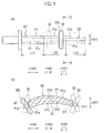
Fig. 1] Fig. 1 (a) is a schematic view illustrating a first finishing step in a wing surface finishing method according to a first embodiment of the present invention, which shows applying finishing processing to a leading edge and a trailing edge of a wing surface corresponding area.Fig. 1 (b) is a view along a line IB-IB inFig. 1 (a) . - [
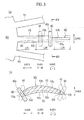
Fig. 2] Fig. 2 (a) is a schematic view illustrating a second finishing step and a third finishing step in the wing surface finishing method according to the first embodiment of the present invention, which shows applying finishing processing to a ventral portion and a back portion of the wing surface corresponding area.Fig. 2(b) is a view along a line IIB-IIB inFig. 2(a) . - [
Fig. 3] Fig. 3 (a) is a schematic view illustrating a first finishing step in a wing surface finishing method according to a second embodiment of the present invention, which shows applying finishing processing to a leading edge and a trailing edge of a wing surface corresponding area.Fig. 3 (b) is a view along a line IIIB-IIIB inFig. 3 (a) . - [
Fig. 4 ] JFig. 4 (a) is a schematic view illustrating a second finishing step and a third finishing step in the wing surface finishing method according to the second embodiment of the present invention, which shows applying finishing processing to a ventral portion and a back portion of the wing surface corresponding area.Fig. 4(b) is a view along a line IVB-IVB inFig. 4(a) . - [
Fig. 5] Fig. 5 (a) is a schematic view illustrating a conventional technique of finishing a wing surface corresponding area (a leading edge and a trailing edge are included) of a workpiece into a wing surface of a wing component.Fig. 5 (b) is a view along a line VB-VB inFig. 5(a) . - [
Fig. 6] Fig. 6 (a) is a schematic view illustrating a conventional technique of finishing a wing surface corresponding area (a leading edge and a trailing edge are included) of a workpiece into a wing surface of a wing wheel component member.Fig. 6 (b) is a view along a line VIB-VIB inFig. 6(a) . - A first embodiment of the present invention will be explained with reference to
Figs. 1 and2 . - As shown in
Figs. 1 and2 , a wing surface finishing method according to the embodiment is the method for applying finishing processing to a wing surface corresponding area P1 of a roughly-processed workpiece W1 set to a work jig (not shown) of a machining center, and finishing it into a wing surface S1 of a wing component M1 as a wing member. In addition, in the wing surface finishing method according to the embodiment, the wing surface corresponding area P1 of the workpiece W1 is divided into a plurality of (three in the first embodiment) sections L1A, L1B, and L1C from a tip to a base end, and a series of steps including a first finishing step (1-1), a second finishing step (1-2), a third finishing step (1-3), and a fourth finishing step (1-4) is sequentially executed from a tip side in the plurality of sections L1A, L1B, and L1C. Note that execution of each step in the section LIB is shown inFigs. 1 and2 . - The wing surface finishing method according to the embodiment uses a
finishing end mill 30 that is mounted on a spindle (not shown) of the machining center, and that has a diameter smaller than an outer diameter of a finishing end mill 10 (refer toFig. 6 ) . Here, although the finishingend mill 30 rotates around anaxial center 30c by drive of a rotary motor (not shown) of the machining center, feed-movement control and feed-rotation control of thefinishing end mill 30 are performed relatively to the workpiece W1 in feed-movement axis directions and feed-rotation axis directions. In addition, in the first embodiment, although thefinishing end mill 30 is a radius end mill, it may be a ball end mill. Note that in the first embodiment, the feed-movement axis directions mean an X-axis direction, a Y-axis direction, and a Z-axis direction perpendicular to each other, and that the feed-rotation axis directions mean an A-axis direction, which is the direction to rotate around an axial center parallel to the Y-axis direction, and a B-axis direction, which is the direction to rotate around an axial center parallel to the X-axis direction. - Subsequently, specific contents of each step in the wing surface finishing method according to the embodiment will be explained.
- As shown in
Figs. 1(a) and 1(b) , thefinishing end mill 30 is given infeed in a radial direction thereof, and is fed and moved repeatedly a plurality of times to the workpiece W1 along a leading edge P1a of the wing surface corresponding area P1 of the workpiece W1, while being rotated around theaxial center 30c in a state where theaxial center 30c of thefinishing end mill 30 is crossed in a spanwise direction of the wing surface corresponding area P1 of the workpiece W1, by driving a rotary motor, and performing feed-movement control and feed-rotation control of thefinishing end mill 30 with respect to the workpiece W1 in the feed-movement axis directions and the feed-rotation axis directions. As a result of this, for each section L1A (L1B, L1C), finishing processing is applied to the leading edge P1a of the wing surface corresponding area P1 of the workpiece W1 by an outer peripheral portion (an outer peripheral cutting edge) of thefinishing end mill 30, and the leading edge P1a of the wing surface corresponding area P1 of the workpiece W1 is finished into a leading edge S1a of the wing surface S1 of the wing component M1. - Similarly, as shown in
Figs. 1(a) and 1(b) , the finishingend mill 30 is given infeed in the axial direction thereof, and is fed and moved repeatedly a plurality of times to the workpiece W1 along a trailing edge P1t of the wing surface corresponding area P1 of the workpiece W1, while being rotated around theaxial center 30c in the state where theaxial center 30c of thefinishing end mill 30 is crossed in the spanwise direction of the wing surface corresponding area P1 of the workpiece W1. As a result of this, for each section L1A (LIB, L1C), finishing processing is applied to the trailing edge P1t of the wing surface corresponding area P1 of the workpiece W1 by the outer peripheral portion of thefinishing end mill 30, and the trailing edge P1t of the wing surface corresponding area P1 of the workpiece W1 is finished into a trailing edge Sit of the wing surface S1 of the wing component M1. - After end of the first finishing step (1-1), as shown in
Figs. 2 (a) and 2 (b) , thefinishing end mill 30 is given infeed in an axial direction thereof, is made to approach the workpiece W1 after a speed thereof is increased, and is fed and moved relatively to the workpiece W1 along a ventral portion P1v from a leading edge P1a side (or a trailing edge P1t side) of the wing surface corresponding area P1 of the workpiece W1, while being rotated around theaxial center 30c thereof in a state where a tip of thefinishing end mill 30 is made to face the wing surface corresponding area P1 of the workpiece W1, by driving the rotary motor, and performing feed-movement control and feed-rotation control of thefinishing end mill 30 with respect to the workpiece W1 in the feed-movement axis directions and the feed-rotation axis directions. At this time, finishing processing is applied only to the ventral portion P1v of the wing surface corresponding area P1 of the workpiece W1 by a shoulder of the tip of thefinishing end mill 30, and the speed of thefinishing end mill 30 is decreased after thefinishing end mill 30 is moved away from the wing surface corresponding area P1 of the workpiece W1. - After end of the second finishing step (1-2), as shown in
Figs. 2 (a) and 2(b) , thefinishing end mill 30 is given infeed in the axial direction thereof, is made to approach the workpiece W1 after the speed thereof is increased, and is fed and moved relatively to the workpiece W1 along a back portion P1b from the trailing edge P1t side (or the leading edge P1a side) of the wing surface corresponding area P1 of the workpiece W1, while being rotated around theaxial center 30c thereof in the state where the tip of thefinishing end mill 30 is made to face the wing surface corresponding area P1 of the workpiece W1, by driving the rotary motor, and performing feed-movement control and feed-rotation control of thefinishing end mill 30 with respect to the workpiece W1 in the feed-movement axis directions and the feed-rotation axis directions. At this time, finishing processing is applied only to the back portion P1b of the wing surface corresponding area P1 of the workpiece W1 by the shoulder of the tip of thefinishing end mill 30, and the speed of thefinishing end mill 30 is decreased after thefinishing end mill 30 is moved away from the wing surface corresponding area P1 of the workpiece W1. - After end of the third finishing step (1-3), processing of the second finishing step (1-2) and the third finishing step (1-3) is alternately repeated, while giving to the finishing
end mill 30 pitch feed in the spanwise direction (a longitudinal direction) of the wing surface corresponding area P1 of the workpiece W1, by driving the rotary motor, and performing feed-movement control and feed-rotation control of the finishingend mill 30 with respect to the workpiece W1 in the feed-movement axis directions and the feed-rotation axis directions. As a result of this, for each section L1A (LIB, L1C), the ventral portion P1v and the back portion P1b of the wing surface corresponding area P1 of the workpiece W1 can be finished into a ventral portion S1v and a back portion S1b of the wing surface S1 of the wing component M1. - Note that instead of applying finishing processing to the ventral portion P1v of the wing surface corresponding area P1 of the workpiece W1 in the second finishing step (1-2), and applying finishing processing to the back portion P1b of the wing surface corresponding area P1 of the workpiece W1 in the third finishing step (1-3), finishing processing may be applied to the back portion P1b of the wing surface corresponding area P1 of the workpiece W1 in the second finishing step (1-2), and finishing processing may be applied to the ventral portion P1v of the wing surface corresponding area P1 of the workpiece W1 in the third finishing step (1-3) .
- Subsequently, actions and effects of the embodiment will be explained.
- After finishing of the leading edge S1a and the trailing edge S1t and finishing of the ventral portion S1v and the back portion S1b in the wing surface S1 of the wing component M1 are separated into separate steps, finishing processing is applied to the ventral portion P1v and the back portion P1b of the wing surface corresponding area P1 of the workpiece W1, respectively, and increasing and decreasing the speed of the finishing
end mill 30 are performed while the finishingend mill 30 is away from the wing surface corresponding area P1 of the workpiece W1. Therefore, even if a relative feed-movement speed of the finishingend mill 30 becomes higher along with increase in a cutting speed of the finishingend mill 30, decrease in a relative feed amount per cutting edge due to change in direction of the finishingend mill 30 can be suppressed near the leading edge P1a and a trailing edge P2t of the wing surface corresponding area P1 of the workpiece W1. - In addition, the wing surface corresponding area P1 of the workpiece W1 is divided into the plurality of sections L1A, L1B, and L1C from the tip to the base end, and the series of steps including the first finishing step (1-1), the second finishing step (1-2), the third finishing step (1-3), and the fourth finishing step (1-4) is executed for each section L1A (LIB, L1C). Therefore, rapid deterioration of rigidity of the wing surface corresponding area P1 of the workpiece W1 in the middle of performing finishing processing thereof can be suppressed.
- Accordingly, according to the embodiment, even if the relative feed-movement speed of the finishing
end mill 30 becomes higher along with increase in the cutting speed of the finishingend mill 30, decrease in the relative feed amount per cutting edge of the finishingend mill 30 near the leading edge P1a and the trailing edge P1t of the wing surface corresponding area P1 of the workpiece W1 can be suppressed. Therefore, large frictional heat can be suppressed from being generated between the finishingend mill 30 and the workpiece W1 to thereby maintain durability of the finishingend mill 30, while improving productivity of finishing of the wing surface S1 of the wing component M1. - In addition, since rapid deterioration of the rigidity of the wing surface corresponding area P1 of the workpiece W1 in the middle of performing finishing processing thereof can be suppressed, chattering of the workpiece W1 can be reduced, and finishing accuracy of the wing surface S1 of the wing component M1 can be improved.
- A second embodiment of the present invention will be explained with reference to
Figs. 3 and4 . - As shown in
Figs. 3 and4 , a wing surface finishing method according to the embodiment is the method for applying finishing processing to a wing surface corresponding area P2 of a roughly-processed workpiece W2 set to a work jig (not shown) of a machining center, and finishing the wing surface corresponding area P2 of the workpiece W2 into a wing surface S2 of a wing wheel component member M2 as a wing member. In addition, in the wing surface finishing method according to the embodiment, the wing surface corresponding area P2 of the workpiece W2 is divided into a plurality of (three in the second embodiment) sections L2A, L2B, and L2C from a tip to a base end, and a series of steps including a first finishing step (2-1), a second finishing step (2-2), a third finishing step (2-3), and a fourth finishing step (2-4) is sequentially executed from a tip side in the plurality of sections L2A, L2B, and L2C. Note that execution of each step in the section L2B is shown inFigs. 3 and4 . - The wing surface finishing method according to the embodiment uses a finishing
end mill 40 that is mounted on a spindle (not shown) of the machining center, and that has a diameter smaller than an outer diameter of the finishing end mill 20 (refer toFig. 6 ). In addition, the finishingend mill 40 may be a radius end mill or a ball end mill. Here, although the finishingend mill 40 rotates around anaxial center 40c by drive of a rotary motor (not shown) of the machining center, feed-movement control and feed-rotation control of the finishingend mill 40 are performed relatively to the workpiece W2 in the feed-movement axis directions (the X-axis direction, the Y-axis direction, and the Z-axis direction) and the feed-rotation axis directions (the A-axis direction and the B-axis direction). - Subsequently, specific contents of each step in the wing surface finishing method according to the embodiment will be explained.
- As shown in
Figs. 3(a) and 3(b) , similarly to the first finishing step (1-1) in the wing surface finishing method according to the first embodiment of the present invention, by executing the first finishing step (2-1), for each section L2A (L2B, L2C) of the wing surface corresponding area P2 of the workpiece W2, finishing processing is applied to a leading edge P2a and a trailing edge P2t of the wing surface corresponding area P2 of the workpiece W2 by an outer peripheral portion (an outer peripheral cutting edge) of the finishingend mill 40, and the leading edge P2a and the trailing edge P2t of the wing surface corresponding area P2 of the workpiece W2 are finished into a leading edge S2a and a trailing edge S2t of the wing surface S2 of the wing wheel component member M2. - After end of the first finishing step (2-1), as shown in
Figs. 4 (a) and 4(b) , the finishingend mill 40 is given infeed in a radial direction thereof, is made to approach the workpiece W2 after a speed thereof is increased, and is fed and moved relatively to the workpiece W2 along a ventral portion P2v from a leading edge P2a side (or a trailing edge P2t side) of the wing surface corresponding area P2 of the workpiece W2, in a state where a tip of the finishingend mill 40 is directed to a base end side of the wing surface corresponding area P2 of the workpiece W2 (i.e., a state where the finishingend mill 40 is located along the wing surface corresponding area P2 of the workpiece W2), by driving the rotary motor, and performing feed-movement control and feed-rotation control of the finishingend mill 40 with respect to the workpiece W2 in the feed-movement axis directions and the feed-rotation axis directions. At this time, finishing processing is applied only to the ventral portion P2v of the wing surface corresponding area P2 of the workpiece W2 by a shoulder of the tip of the finishingend mill 40, and the finishingend mill 40 is moved away from the wing surface corresponding area P2 of the workpiece W2. - Note that a reason that the tip of the finishing
end mill 40 is made to be in the state of being directed to the base end side of the wing surface corresponding area P2 of the workpiece W2 is to prevent the finishingend mill 40 form interfering with another wing surface corresponding area P2 adjacent to the unfinished wing surface corresponding area P2. - After end of the second finishing step (1-2), as shown in
Figs. 4(a) and 4(b) , the finishingend mill 40 is given infeed in the radial direction thereof, is made to approach the workpiece W2 after the speed thereof is increased, and is fed and moved relatively to the workpiece W2 along a back portion P2b from the trailing edge P2t side (or the leading edge P2a side) of the wing surface corresponding area P2 of the workpiece W2, in the state where the tip of the finishingend mill 40 is directed to the base end side of the wing surface corresponding area P2 of the workpiece W2, by driving the rotary motor, and performing feed-movement control and feed-rotation control of the finishingend mill 40 with respect to the workpiece W2 in the feed-movement axis directions and the feed-rotation axis directions. Finishing processing is applied only to the back portion P2b of the wing surface corresponding area P2 of the workpiece W2 by the shoulder of the tip of the finishingend mill 40, and the finishingend mill 40 is moved away from the wing surface corresponding area P2 of the workpiece W2. - Note that instead of applying finishing processing to the ventral portion P2v of the wing surface corresponding area P2 of the workpiece W2 in the second finishing step (2-2), and applying finishing processing to the back portion P2b of the wing surface corresponding area P2 of the workpiece W2 in the third finishing step (1-3), finishing processing may be applied to the back portion P2b of the wing surface corresponding area P2 of the workpiece W2 in the second finishing step (2-2), and finishing processing may be applied to the ventral portion P2v of the wing surface corresponding area P2 of the workpiece W2 in the third finishing step (1-3).
- After end of the third finishing step (2-3), the second finishing step (2-2) and the third finishing step (2-3) are alternately repeatedly executed, while giving pitch feed in a spanwise direction of the workpiece W2 to the finishing
end mill 40, by driving the rotary motor, and performing feed-movement control and feed-rotation control of the finishingend mill 40 with respect to the workpiece W2 in the feed-movement axis directions and the feed-rotation axis directions. As a result of this, for each section L2A (L2B, L2C) of the wing surface corresponding area P2 of the workpiece W2, the ventral portion P2v and the back portion P2b of the wing surface corresponding area P2 of the workpiece W2 can be finished into a ventral portion S2v and a back portion S2b of the wing surface S2 of the wing wheel component member M2. - Subsequently, actions and effects of the embodiment will be explained.
- After finishing of the leading edge S2a and the trailing edge S2t and finishing of the ventral portion S2v and the back portion S2b in the wing surface S2 of the wing wheel component member M2 are separated into separate steps, finishing processing is applied to the ventral portion P2v and the back portion P2b of the wing surface corresponding area P2 of the workpiece W2, respectively, and increasing and decreasing the speed of the finishing
end mill 40 are performed while the finishingend mill 40 is away from the wing surface corresponding area P2 of the workpiece W2. Therefore, even if a relative feed-movement speed of the finishingend mill 40 becomes higher along with increase in the cutting speed of the finishingend mill 40, decrease in a relative feed amount per cutting edge due to change in direction of the finishingend mill 40 can be suppressed near the leading edge P2a and the trailing edge P2t of the wing surface corresponding area P2 of the workpiece W2. - In addition, the wing surface corresponding area P2 of the workpiece W2 is divided into the plurality of sections L2A, L2B, and L2C from the tip to the base end, and the series of steps including the first finishing step (1-1), the second finishing step (1-2), the third finishing step (1-3), and the fourth finishing step (1-4) is executed for each section L2A (L2B, L2C). Therefore, rapid deterioration of rigidity of the wing surface corresponding area P2 of the workpiece W2 in the middle of performing finishing processing thereof can be suppressed.
- Accordingly, according to the embodiment, the effects similar to the above-mentioned first embodiment are exerted.
- The present invention is not limited to the explanation of the above-mentioned embodiments, and can be carried out in various aspects. In addition, the scope of right embraced in the present invention also covers the wing members, such as the wing component M1 finished by the wing surface finishing method according to the first embodiment of the present invention, and the wing wheel component member M2 finished by the wing surface finishing method according to the second embodiment of the present invention.
- In the present invention, even if a relative feed-movement speed of a finishing end mill becomes higher, decrease in a relative feed amount per cutting edge of the finishing end mill can be suppressed. Therefore, the present invention can provide a wing surface finishing method that suppresses generation of large frictional heat between the finishing end mill and the workpiece to thereby maintain durability of the finishing end mill, while improving productivity of finishing of the wing surface of the wing member.
Claims (3)
- A wing surface finishing method for applying finishing processing to a wing surface corresponding area of a roughly-processed workpiece, and finishing the wing surface corresponding area of the workpiece into a wing surface of a wing member, the wing surface finishing method comprising:a first finishing step of applying finishing processing to a leading edge and a trailing edge of the wing surface corresponding area of the workpiece, and finishing the leading edge and trailing edge of the wing surface corresponding area of the workpiece into a leading edge and a trailing edge of the wing surface of the wing member, by giving infeed to a finishing end mill, and feeding and moving the finishing end mill relatively to the workpiece along the leading edge and the trailing edge of the wing surface corresponding area of the workpiece, while rotating the finishing end mill around an axial center thereof;a second finishing step of applying finishing processing only to one of a ventral portion and a back portion of the wing surface corresponding area of the workpiece, and decreasing a speed of the finishing end mill after moving the finishing end mill away from the wing surface corresponding area of the workpiece, by giving infeed to the finishing end mill, making the finishing end mill approach the workpiece after increasing the speed of the finishing end mill, and feeding and moving the finishing end mill relatively to the workpiece along the one of the ventral portion and the back portion from a leading edge side or a trailing edge side of the wing surface corresponding area of the workpiece, while rotating the finishing end mill around the axial center thereof;a third finishing step of applying finishing processing only to the other of the ventral portion and the back portion of the wing surface corresponding area of the workpiece, and decreasing the speed of the finishing end mill after moving the finishing end mill away from the wing surface corresponding area of the workpiece, by giving infeed to the finishing end mill, making the finishing end mill approach the workpiece after increasing the speed of the finishing end mill, and feeding and moving the finishing end mill relatively to the workpiece along the other of the ventral portion and the back portion from the trailing edge side or the leading edge side of the wing surface corresponding area of the workpiece, while rotating the finishing end mill around the axial center thereof, after end of the second finishing step; anda fourth finishing step of finishing the ventral portion and the back portion of the wing surface corresponding area of the workpiece into a ventral portion and a back portion of the wing surface of the wing member, by alternately repeatedly executing the second finishing step and the third finishing step while giving to the finishing end mill pitch feed in a spanwise direction of the wing surface corresponding area of the workpiece, after end of the third finishing step.
- The wing surface finishing method according to claim 1, wherein the wing surface corresponding area of the workpiece is divided into a plurality of sections from a tip to a base end, and a series of steps including the first finishing step, the second finishing step, the third finishing step, and the fourth finishing step is executed in the plurality of sections.
- A wing component comprising a wing surface finished by the wing surface finishing method according to claim 1 or 2.
Applications Claiming Priority (1)
| Application Number | Priority Date | Filing Date | Title |
|---|---|---|---|
| PCT/JP2013/062995 WO2014181418A1 (en) | 2013-05-09 | 2013-05-09 | Wing surface finishing method and wing component |
Publications (2)
| Publication Number | Publication Date |
|---|---|
| EP2995404A1 true EP2995404A1 (en) | 2016-03-16 |
| EP2995404A4 EP2995404A4 (en) | 2017-01-11 |
Family
ID=51866922
Family Applications (1)
| Application Number | Title | Priority Date | Filing Date |
|---|---|---|---|
| EP13884227.3A Withdrawn EP2995404A4 (en) | 2013-05-09 | 2013-05-09 | Wing surface finishing method and wing component |
Country Status (5)
| Country | Link |
|---|---|
| US (1) | US9694430B2 (en) |
| EP (1) | EP2995404A4 (en) |
| CN (1) | CN105358277A (en) |
| RU (1) | RU2615853C1 (en) |
| WO (1) | WO2014181418A1 (en) |
Families Citing this family (1)
| Publication number | Priority date | Publication date | Assignee | Title |
|---|---|---|---|---|
| US11642748B2 (en) | 2020-01-23 | 2023-05-09 | Fanuc Corporation | Machining program creation method, workpiece machining method, and machine tool control device |
Family Cites Families (26)
| Publication number | Priority date | Publication date | Assignee | Title |
|---|---|---|---|---|
| US3295190A (en) * | 1964-01-16 | 1967-01-03 | Parsons Corp | Method of machining metal castings for screw propellers and the like |
| DE2544612C3 (en) * | 1974-10-14 | 1980-04-10 | Leningradskoe Specialnoe Konstruktorskoe Bjuro Tyaschelych I Unikalnych Stankov, Leningrad (Sowjetunion) | Round milling process |
| SU1093433A1 (en) * | 1983-01-06 | 1984-05-23 | Ленинградское Специальное Конструкторское Бюро Тяжелых И Уникальных Станков | Method of machining turbine blades |
| CH661678A5 (en) * | 1983-12-16 | 1987-08-14 | Starrfraesmaschinen Ag | Method for machining a shovel-shaped workpiece by a milling tool |
| JPS60197308A (en) * | 1984-03-14 | 1985-10-05 | Toshiaki Hosoi | Profile milling method |
| SU1255303A1 (en) * | 1985-01-04 | 1986-09-07 | Новополоцкий Политехнический Институт Им.Ленинского Комсомола Белоруссии | Method of machining complex surfaces |
| JPS62225702A (en) * | 1986-03-28 | 1987-10-03 | Mitsui Seiki Kogyo Co Ltd | Multi-row rotor blade and its processing method |
| JPS62264814A (en) * | 1986-05-09 | 1987-11-17 | Mitsubishi Heavy Ind Ltd | Cutting method for curved surface |
| ES2102885T3 (en) * | 1993-09-29 | 1997-08-01 | Siemens Ag | PROCEDURE FOR MILLING A PROFILE OF TURBINE ALBUM THAT EXTENDS ALONG A MAIN AXIS. |
| JPH08141815A (en) * | 1994-11-22 | 1996-06-04 | Toyota Motor Corp | Recessing method |
| DE19607192A1 (en) * | 1996-02-26 | 1997-01-16 | Siemens Ag | CNC-programmable workpiece machining system using rotary milling tool - uses translatory movement of milling tool across workpiece surface with its rotation axis at given angle to surface normal |
| JP2000233310A (en) * | 1999-02-17 | 2000-08-29 | Toshiba Corp | Cutting method |
| EP1034865B1 (en) * | 1999-03-08 | 2001-08-22 | ALSTOM (Schweiz) AG | Milling method |
| DE10031441B4 (en) * | 2000-06-28 | 2006-10-12 | Open Mind Technologies Ag | Method for controlling the working movement of a milling tool |
| JP2002036020A (en) * | 2000-07-31 | 2002-02-05 | Ishikawajima Harima Heavy Ind Co Ltd | Processing method of large impeller |
| FR2828824B1 (en) * | 2001-08-23 | 2003-12-05 | Snecma Moteurs | METHOD FOR MANUFACTURING A ROTOR BLOCK BLOCK DISK AND CORRESPONDING DISC |
| JP4183058B2 (en) * | 2001-11-30 | 2008-11-19 | 株式会社Ihi | Blade cutting method |
| CN1186157C (en) * | 2002-12-05 | 2005-01-26 | 西安交通大学 | Drum taper tool and method for side milling complex cambered centrifugal impeller using drum taper tool |
| DE10312224B3 (en) * | 2003-03-19 | 2004-10-28 | Mtu Aero Engines Gmbh | Process for the production of components subject to flow |
| CN1978107A (en) * | 2005-12-02 | 2007-06-13 | 董希武 | Vortex-pump vane numerical controlled milling technology |
| US7793403B2 (en) * | 2005-12-27 | 2010-09-14 | Konica Minolta Opto, Inc. | Manufacturing method of optical component or molding die therefor |
| RU2325985C1 (en) * | 2006-09-28 | 2008-06-10 | Ооо "Ковосвит-Русь" | Device for mounting and fixing turbine blades and method of their milling with device |
| DE102008017624A1 (en) * | 2008-04-04 | 2009-10-08 | Rolls-Royce Deutschland Ltd & Co Kg | Method for aerodynamically shaping the leading edge of blisk blades |
| DE102010060220B4 (en) * | 2010-10-28 | 2013-07-11 | Gebr. Heller Maschinenfabrik Gmbh | Method for processing freeform surfaces |
| JP5842557B2 (en) * | 2011-11-11 | 2016-01-13 | 株式会社Ihi | Blade finishing method and blade parts |
| CN102950316A (en) * | 2012-11-26 | 2013-03-06 | 哈尔滨汽轮机厂有限责任公司 | Processing method of sub-last stage blade with good blade profile stability of large turbine |
-
2013
- 2013-05-09 RU RU2015152043A patent/RU2615853C1/en active
- 2013-05-09 EP EP13884227.3A patent/EP2995404A4/en not_active Withdrawn
- 2013-05-09 WO PCT/JP2013/062995 patent/WO2014181418A1/en not_active Ceased
- 2013-05-09 CN CN201380076345.9A patent/CN105358277A/en active Pending
-
2015
- 2015-11-05 US US14/933,589 patent/US9694430B2/en active Active
Also Published As
| Publication number | Publication date |
|---|---|
| CN105358277A (en) | 2016-02-24 |
| US9694430B2 (en) | 2017-07-04 |
| EP2995404A4 (en) | 2017-01-11 |
| RU2615853C1 (en) | 2017-04-11 |
| WO2014181418A1 (en) | 2014-11-13 |
| US20160052071A1 (en) | 2016-02-25 |
Similar Documents
| Publication | Publication Date | Title |
|---|---|---|
| Caixu et al. | A review of chatter vibration research in milling | |
| US8690498B2 (en) | Cutting machining method and cutting machining apparatus | |
| JP5108106B2 (en) | Throw-away cutting rotary tool | |
| US9662727B2 (en) | Machine tool for threading processes | |
| US9690283B2 (en) | Machine tool for a threading process | |
| US9144854B2 (en) | Method of generating gear teeth, and a gear-cutting machine that is operable according to said method | |
| CN105234466A (en) | Slot feature side milling machining tool path generating method | |
| CN103624304A (en) | Method for machining axially changed spatial arc slots | |
| US20220379389A1 (en) | Endmill specification design method, cutting condition detecting method, and processing method | |
| US9122257B2 (en) | Thread cutting machine | |
| JP5842557B2 (en) | Blade finishing method and blade parts | |
| CN105538036A (en) | Method of controlling feed axes in machine tool and machine tool | |
| JPWO2017017720A1 (en) | Groove processing method | |
| JP6565399B2 (en) | Gear processing equipment | |
| US9694430B2 (en) | Wing surface finishing method and wing component | |
| CN104308370A (en) | Quick circular arc cutting method | |
| JP2011161542A (en) | Machine tool and polygon machining method | |
| RU2463129C1 (en) | Method of machining shaped shaft with identical-width sides | |
| JP5842554B2 (en) | Grooving method | |
| KR20140078461A (en) | Control method for CNC machine tool | |
| JP2013006224A (en) | Machine tool | |
| JP2016221598A (en) | Hob cutter | |
| EP2897749B1 (en) | Milling cutter and method of use | |
| JP2015006713A (en) | Gear processing equipment | |
| WO2013008768A1 (en) | Cutting tool with exchangeable cutting edges |
Legal Events
| Date | Code | Title | Description |
|---|---|---|---|
| PUAI | Public reference made under article 153(3) epc to a published international application that has entered the european phase |
Free format text: ORIGINAL CODE: 0009012 |
|
| 17P | Request for examination filed |
Effective date: 20151207 |
|
| AK | Designated contracting states |
Kind code of ref document: A1 Designated state(s): AL AT BE BG CH CY CZ DE DK EE ES FI FR GB GR HR HU IE IS IT LI LT LU LV MC MK MT NL NO PL PT RO RS SE SI SK SM TR |
|
| AX | Request for extension of the european patent |
Extension state: BA ME |
|
| DAX | Request for extension of the european patent (deleted) | ||
| A4 | Supplementary search report drawn up and despatched |
Effective date: 20161213 |
|
| RIC1 | Information provided on ipc code assigned before grant |
Ipc: B23C 5/10 20060101ALI20161207BHEP Ipc: B23C 3/18 20060101AFI20161207BHEP |
|
| STAA | Information on the status of an ep patent application or granted ep patent |
Free format text: STATUS: EXAMINATION IS IN PROGRESS |
|
| 17Q | First examination report despatched |
Effective date: 20170830 |
|
| STAA | Information on the status of an ep patent application or granted ep patent |
Free format text: STATUS: THE APPLICATION IS DEEMED TO BE WITHDRAWN |
|
| 18D | Application deemed to be withdrawn |
Effective date: 20230301 |