EP2995219B2 - Oral care products - Google Patents
Oral care products Download PDFInfo
- Publication number
- EP2995219B2 EP2995219B2 EP15189735.2A EP15189735A EP2995219B2 EP 2995219 B2 EP2995219 B2 EP 2995219B2 EP 15189735 A EP15189735 A EP 15189735A EP 2995219 B2 EP2995219 B2 EP 2995219B2
- Authority
- EP
- European Patent Office
- Prior art keywords
- oral care
- cross sectional
- transverse cross
- mold
- flexible
- Prior art date
- Legal status (The legal status is an assumption and is not a legal conclusion. Google has not performed a legal analysis and makes no representation as to the accuracy of the status listed.)
- Active
Links
Images


Classifications
-
- A—HUMAN NECESSITIES
- A46—BRUSHWARE
- A46B—BRUSHES
- A46B9/00—Arrangements of the bristles in the brush body
- A46B9/02—Position or arrangement of bristles in relation to surface of the brush body, e.g. inclined, in rows, in groups
- A46B9/04—Arranged like in or for toothbrushes
-
- A—HUMAN NECESSITIES
- A61—MEDICAL OR VETERINARY SCIENCE; HYGIENE
- A61C—DENTISTRY; APPARATUS OR METHODS FOR ORAL OR DENTAL HYGIENE
- A61C17/00—Devices for cleaning, polishing, rinsing or drying teeth, teeth cavities or prostheses; Saliva removers; Dental appliances for receiving spittle
- A61C17/02—Rinsing or air-blowing devices, e.g. using fluid jets or comprising liquid medication
- A61C17/0211—Rinsing or air-blowing devices, e.g. using fluid jets or comprising liquid medication specially adapted for rinsing the teeth of at least one jaw simultaneously
Definitions
- the present invention relates to Oral care cleaning implements, devices, and systems having flexible elements, particularly flexible, elastomeric elements, and methods of using and making the same.
- WO 2008/135953 discloses oral hygiene implements, such as manual or electric toothbrushes or refills, including a head portion sized for insertion into a human mouth.
- the implement has a base and a plurality of elastomeric elements extending from the base to define a field of elastomeric bristles.
- the field can include a first elastomeric element that includes a first elastomeric material and a second elastomeric element different than the first elastomeric element that includes a second elastomeric material.
- the elastomeric elements extending from the base can define many "sharp" edges for enhanced cleaning with reduced abrasion.
- the several embodiments presented herein are directed to oral care systems and/or oral care implements comprising a base and a plurality of flexible, elastomeric elements, and methods of using and making the same.
- An oral care implement according to claim 1 is provided.
- the oral care implement includes, at least in part, a base portion sized for insertion into an oral cavity and a plurality of flexible, elastomeric elements extending from the base portion, wherein at least one of the plurality of flexible, elastomeric elements comprises a first section having a first section edge and a first transverse cross sectional area, and wherein a second section disposed adjacent to the first section along a longitudinal axis of the at least one of the plurality of flexible, elastomeric elements.
- the second section includes a second section edge and a second transverse cross sectional area different from the first transverse cross sectional area.
- Yet another embodiment may comprise an oral care implement that includes, at least in part, a base portion sized for insertion into an oral cavity, the base portion having a base wall and two opposed, side walls connected to the base wall that form a channel for receiving teeth within an oral cavity, and a plurality of flexible, elastomeric elements extending into the channel from the base and two opposed, side walls.
- the implements 2050 may be driven back toward the teeth 2020 and gums 2010 ("Impact") a distance from the teeth 2020 and gums 2010 ("Lift off') a distance from about 0 mm to about 10 mm, particularly from Hz about 0 mm to about 8 mm, particularly from about 3 mm to about 7 mm, particularly from about 4 mm to about 6 mm, or more particularly from about 0 mm to about 5 mm.
Landscapes
- Health & Medical Sciences (AREA)
- Public Health (AREA)
- Epidemiology (AREA)
- Life Sciences & Earth Sciences (AREA)
- Animal Behavior & Ethology (AREA)
- General Health & Medical Sciences (AREA)
- Dentistry (AREA)
- Veterinary Medicine (AREA)
- Brushes (AREA)
- Cosmetics (AREA)
- Dental Tools And Instruments Or Auxiliary Dental Instruments (AREA)
- Jellies, Jams, And Syrups (AREA)
- Orthopedics, Nursing, And Contraception (AREA)
Description
- The present invention relates to Oral care cleaning implements, devices, and systems having flexible elements, particularly flexible, elastomeric elements, and methods of using and making the same.
- Although many innovations have been made in the field of oral health care, there is a continuing need for oral care products and methods which can improve the health and appearance of the oral cavity and teeth, such as teeth cleaning, teeth whitening, and plaque removal. For example,
WO 2008/135953 discloses oral hygiene implements, such as manual or electric toothbrushes or refills, including a head portion sized for insertion into a human mouth. The implement has a base and a plurality of elastomeric elements extending from the base to define a field of elastomeric bristles. The field can include a first elastomeric element that includes a first elastomeric material and a second elastomeric element different than the first elastomeric element that includes a second elastomeric material. The elastomeric elements extending from the base can define many "sharp" edges for enhanced cleaning with reduced abrasion. - The several embodiments presented herein are directed to oral care systems and/or oral care implements comprising a base and a plurality of flexible, elastomeric elements, and methods of using and making the same.
- An oral care implement according to
claim 1 is provided. - The oral care implement includes, at least in part, a base portion sized for insertion into an oral cavity and a plurality of flexible, elastomeric elements extending from the base portion, wherein at least one of the plurality of flexible, elastomeric elements comprises a first section having a first section edge and a first transverse cross sectional area, and wherein a second section disposed adjacent to the first section along a longitudinal axis of the at least one of the plurality of flexible, elastomeric elements. The second section includes a second section edge and a second transverse cross sectional area different from the first transverse cross sectional area.
- Yet another embodiment may comprise an oral care implement that includes, at least in part, a base portion sized for insertion into an oral cavity, the base portion having a base wall and two opposed, side walls connected to the base wall that form a channel for receiving teeth within an oral cavity, and a plurality of flexible, elastomeric elements extending into the channel from the base and two opposed, side walls. Each of the plurality of flexible, elastomeric elements comprises an edge and a longitudinal axis, wherein at least one of the plurality of flexible, elastomeric elements comprises a first section having a first transverse cross sectional area and a second section having a second transverse cross sectional area that is disposed adjacent to the first section along the longitudinal axis of the at least one flexible, elastomeric element, and wherein the second transverse cross sectional area is different than the first transverse cross sectional area.
- Still yet another embodiment may comprise a method of forming a micro edge of an flexible, elastomeric element. The method may include the steps of forming a mold cavity with a first mold plate and a second mold plate positioned adjacent to the first mold plate, forming a mold corner of the mold cavity using an intersection of the first mold plate and second mold plate, injecting an elastomer into the mold cavity, and allowing gas contained within the mold cavity to out-gas through the intersection between the first and second mold plates to form as micro edge along the mold corner formed by the intersection.
- While the specification concludes with claims particularly pointing out and distinctly claiming the invention, it is believed the same will be better understood from the following description taken in conjunction with the accompanying drawings in which:
-
FIG. 1A is a perspective view of an oral care implement; -
FIG. 1B is a detail of a lop planar view of a flexible, elastomeric element ofFIG. 1A ; -
FIG. 2A is a top planar view of another embodiment of a flexible, elastomeric element; -
FIG. 2B is a top planar view of another embodiment of a flexible, elastomeric element; -
FIG. 2C is a top planar view of another embodiment of a flexible, elastomeric element; -
FIG. 2D is a top planar view of another embodiment of a flexible, elastomeric element; -
FIG. 2E is a top planar view of another embodiment of a flexible, elastomeric element; -
FIG. 3 is a partial perspective view of another embodiment of an oral care implement; -
FIG. 4 is a perspective view of a flexible, elastomeric element of the oral care implement ofFIG. 3 ; -
FIG. 5 is a side elevational view of the flexible, elastomeric element ofFIG. 4 ; -
FIG. 6 is a top planar view of the flexible, elastomeric element ofFIG. 4 ; -
FIG. 7 is a detail of a top planar view of the flexible, elastomeric element ofFIG. 5 ; -
FIG. 8 is a detail of the flexible, elastomeric element ofFIG. 6 ; -
FIG. 9 is a perspective view of another embodiment of a flexible, elastomeric element; -
FIG. 10 is a side elevational view of the flexible, elastomeric element ofFIG. 9 ; -
FIG. 11 is a top planar view of the flexible, elastomeric element ofFIG. 9 ; -
FIG. 12 is an exploded, perspective view of an embodiment of a mold system in combination with a mold machine; -
FIG. 13 is a perspective view of another embodiment of a flexible, elastomeric element fabricated from the mold system ofFIG. 12 ; -
FIG. 14 is a partial cross sectional view of the mold system ofFIG. 12 ; -
FIG. 15A is a an exploded, perspective view of another embodiment of a mold system; -
FIG. 15B is a partial perspective view of the mold system ofFIG. 15A ; -
FIG. 16 is a perspective view of another embodiment of a flexible, elastomeric element fabricated from the mold system ofFIG. 15A ; -
FIG. 17 is a perspective view of another embodiment of a mold system; -
FIG. 18 is a perspective view of another embodiment of a flexible, elastomeric element fabricated from the mold system ofFIG. 17 ; -
FIG. 19A is a detail of the mold system ofFIG. 17 ; -
FIG. 19B is a detail of the mold system ofFIG. 17 ; -
FIG. 20 is a partial perspective view of another embodiment of a mold system; -
FIG. 21 is a partial cross sectional view of an embodiment of a cavity mold plate of the mold system ofFIG. 20 ; -
FIG. 22 is a schematic representation of an embodiment of an oral care system; -
FIG. 23 is a schematic representation of another embodiment of an oral care implement; -
FIG. 24A is a schematic representation of a top perspective view of another embodiment of a plurality of flexible, elastomeric elements; -
FIG. 24B is a schematic representation of an isometric view of the plurality of flexible, elastomeric elements ofFIG. 24A moving into an interdental area of an oral cavity before engagement with any teeth surfaces within the interdental area; -
FIG. 24C is a schematic representation of an isometric view of the plurality of flexible, elastomeric elements ofFIG. 24A moving into and engaging the interdental area; -
FIG. 24D is a schematic representation of a top perspective view of the plurality of flexible, elastomeric elements ofFIG. 24C , illustrating the initial twisting, bending, and/or deformation of the plurality of flexible, elastomeric elements; -
FIG. 24E is a schematic representation of an isometric view of the plurality of flexible, elastomeric elements ofFIG. 24D moving further into and engaging the interdental area; and -
FIG. 24F is a schematic representation of a top perspective view of the plurality of flexible, elastomeric elements ofFIG. 24E , illustrating the twisting, bending, and/or deformation of the plurality of flexible, elastomeric elements and contact stresses due to the engagement with the interdental area. - As used herein, "an edge" is a line at which two surfaces intersect, or a border at which a surface terminates.
- "Include" and its variants are non-limiting in the sense that recitation of items "included" in a list does not exclude other items.
- As used herein, a "micro" edge is an edge as defined herein that is fabricated to have a tip radius (R) of less than 0.0254 mm, particularly less than or equal to about 0.02 mm, more particularly less than or equal to about 0.015 mm, more particularly less than or equal to about 0.01 mm, more particularly less than or equal to about 0.008 mm, more particularly less than or equal to about 0.0075 mm, more particularly less than or equal to about 0.007 mm, more particularly less than or equal to about 0.0065 mm, more particularly less than or equal to about 0.006 mm, more particularly less than or equal to about 0.0055 mm, more particularly less than or equal to about 0.005 mm, more particularly less than or equal to about 0.0045 mm, more particularly less than or equal to about 0.004 mm, more particularly less than or equal to about 0.0035 mm, more particularly less than or equal to about 0.003 mm, more particularly less than or equal to about 0.0025 mm, more particularly less than or equal to about 0.002 mm, more particularly less than or equal to about 0.0015 mm, more particularly less than or equal to about 0.001 mm, and/or from about 0.0254 mm to about 0.001 mm, from about to 0.02 mm to about 0.001 mm, particularly from about 0.015 mm to about 0.0015 mm, particularly from about 0.01 mm to about 0.002 mm, more particularly from about 0.009 mm to about 0.0025 mm, more particularly from about 0.0085 mm to about 0.0025 mm, and/or more particularly from about 0.008 mm to about 0.0025 nun. One example of a micro edge comprises an out-gassed edge. As used herein, "an out-gassed" edge is an edge. as defined herein, formed by the out-gassing between two cavity mold plates (at the point of engagement between the two cavity mold plates) from a mold cavity used in a molding process such as plastic injection molding. The molding plates are used to form at least a portion of a mold cavity to form an element (e.g., element 10). During the molding process, gas in the mold cavity out-gasses through and between the space located where the two molding plates engage one another (i.e., intersection of the two molding plates), thus pushing and/or pulling the material (e.g., plastic) deep into the corner of the mold cavity formed by the intersection of the two molding plates. When the plastic penetrates into the corner of the mold cavity by the out-gassing process, it forms a micro edge (e.g., micro edge 18) along the flexible element (e.g., element 10).
- "Oral care composition" or "oral composition" means a product which in the ordinary course of usage can be retained in the oral cavity for contacting selected dental surfaces and/or oral tissues for purposes of oral activity. In addition to cleaning teeth to remove dental plaque, oral care compositions may be used to prevent formation of dental calculus and disorders such as caries, periodontitis and gingivitis, and also to eliminate and prevent oral malodor or halitosis and staining. Some examples of oral care product forms are toothpastes, dentifrices, tooth gels, subgingival gels, foams, mouth rinses, denture products, mouth sprays, lozenges, chewable tablets or chewing gums and strips or films for direct application or attachment to oral surfaces including any hard or soft oral tissues.
- As used herein, "oral cavity" means a cavity comprising oral cavity tissue as defined herein, including but not limited to human mouths and/or mouths of other animals.
- As used herein, "oral cavity tissue" means any hard or soft tissue disposed within the oral cavity such as teeth and gum tissue.
- As used herein, the terms "oral condition" and "condition" are used to refer to dental plaque, tanar, debris, tooth decay, bio films, soft tissue abnormalities, soft tissue lesions, etc. within the oral cavity.
- "Orally acceptable additive" means any additive which is now known, or hereinafter becomes known, as a safe and effective additive for an oral care composition. Examples include conventional additives in oral care compositions including but not limited to fluoride ion sources, anti-calculus or anti-tartar agents, desensitizing agents, teeth whitening agents such as peroxide sources, abrasives such as silica, herbal agents, chelating agents, buffers, anti-staining agents, alkali metal bicarbonate salts, thickening materials, humectants, water, surfactants, titanium dioxide, flavor system, sweetening agents, xylitol, coloring agents, and mixtures thereof.
- As used herein, the terms "plaque" and "dental plaque" are used to refer to a bio-film that builds up on teeth, on gingival tissue, oral hard tissue, and/or oral soft tissue.
- "Plaque bacteria" means bacteria that causes plaque to form.
- "Teeth" refers to one or more natural teeth as well as one or more artificial teeth or dental prosthesis.
- Referring to
FIGS. 1-24 , several embodiments of flexible elements (e.g.,flexible elements - As one example, it has been discovered that manipulating one or more of the element and/or oral care implement properties set forth above impact the contact trace (i.e., the path along a tooth's surface that an edge (cleaning edge) of a flexible element contacts the tooth during the cleaning motion). As such, and not to be limited by theory, with the right combination of properties, it has been discovered that the contact trace of one or more of the flexible elements of an oral care element may be controlled, improved, and/or increased, particularly within the interdental areas, and thus improve the cleaning capabilities of such oral care element(s) and/or implement such as, for example, improved interdental cleaning.
- Again, not to be limited by theory, it has been discovered that the contact stress (i.e., the component of the applied force of the flexible element which is normal to the surface of the oral care tissue (tooth or gums) at the point where the edge contacts the oral care tissue divided by the contact area between the edge of the flexible element and the oral care tissue) of one or more of the flexible elements of an oral care implement may be controlled, improved, and/or increased by manipulating the element's edge tip radius, length, spacing with adjacent elements (element density), hardness (durometer), and/or surface friction. It has been discovered that an improved cleaning edge/element configuration can produce high contact stresses over large contact traces (tooth surface areas) for particular cleaning motions.
- The several embodiments shown and described herein are examples of flexible elements and/or oral care cleaning implements that provide such improved oral cleaning benefits.
- Referring to
FIG. 1a , an oral care implement 1 (not comprised by the present invention, but to illustrate certain features which are in accordance with the present invention) is shown, comprising, in part, abase 20 and a plurality ofelements 10 extending from thebase 20. Eachelement 10 may comprise a distal end 12, aproximal end 14 opposite of the distal end 12, a longitudinal axis A-A', and atransverse surface 16 that is disposed transverse to the longitudinal axis A-A'. It is understood that in an element having a different transverse cross sectional shape thanelement 10 shown inFIG. 1A , theedge 18, rather than being a transverse edge, may be a longitudinal edge, i.e., disposed substantially along the longitudinal axis A-A'. In the embodiment shown, thebase 20 and the plurality ofelements 10 are fabricated as one integrated unit. It is understood that thebase 20 and the plurality ofelements 10 may be two separate components that are connected together using conventional techniques and methods of connection such as, for example, adhesives, knotting, sonic welding, etc. - The oral care implement 1 may comprise an implement density of the plurality of
elements 10, which comprises the spacing between eachadjacent element 10. As such, the element density may be measured by measuring the distance (d) between a center point of oneelement 10 to a center point of anadjacent element 10. Thebase 20 and the plurality ofelements 10 may be fabricated such that theelements 10 are equally spaced from each other. In another embodiment, thebase 20 and the plurality ofelements 10 may be fabricated such that the individual elements are unequally separated from each other along thebase 20. In such an embodiment, the clement density is an average of the measured distances between eachelement 10. In one embodiment, thebase 20 has an element density from about 0.05 mm to about 5.0 mm, more particularly from about 0.1 mm to about 3.0 mm, or more particularly from about 0.1 to about 2 mm. Although thebase 20 is shown inFIG. 1A as having a circular shape, it is understood that the base 20 may comprise other configurations, sizes, and shapes, including but not limited to polygon-shaped, elliptical-shaped. U-shaped, U-shaped forming a channel, and other configurations operable to insert into an oral cavity and enable the plurality of bristles to engage the oral cavity tissues therein. -
FIG. 1A shows eachelement 10 having a transverse cross sectional area that remains constant from theproximal end 14 to the distal end 12. In another embodiment, eachelement 10 may taper inwardly toward the longitudinal axis A-A' from theproximal end 14 to the distal end 12. As such, the cross sectional area of theelement 10 transverse to the longitudinal axis A-A' ("transverse cross sectional area") at theproximal end 14 is larger than the transverse cross sectional area at the distal end 12. Alternatively, eachelement 10 may taper outwardly away from the longitudinal axis A-A' from theproximal end 14 to the distal end 12. As such, the transverse cross sectional area of theelement 10 at theproximal end 14 is smaller than the transverse cross sectional area at the distal end 12. In yet another embodiment, the oral care implement 1 may comprise a plurality of elements having constant transverse cross sections, inwardly tapering transverse cross sections, outwardly tapering transverse cross sections, or any combination thereof. - As shown in
FIG. 1A , the plurality ofelements 10 have a round transverse cross sectional shape. As such, theelements 10 shown inFIG. 1A , only comprise oneedge 18 that is transverse to the longitudinal axis A-A' ("transverse edge"). Theedge 18 is disposed at the intersection oftransverse surface 16 andside surface 15.FIG. 1B shows theedge 18 having a tip radius (r). In one embodiment, one or more of the plurality ofelements 10 may be fabricated using the plastic injection method and mold system described below herein such that theedge 18 is a micro edge, wherein the micro edge has a tip radius (r) as defined above herein. Until the discovery of the method and mold system shown and described herein, it was not possible to injection mold plastic, such as an elastomeric material, into mold cavity corners sufficient enough to fabricate micro edges as defined herein. - In another embodiment, the
edge 18 may comprise a tip radius (r) having any conventional value. In yet another embodiment, theedge 18 may comprise a tip radius as shown and described inU.S. Pat. Pub. No. 2009/0007357 . - In other embodiments, the
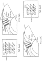
elements 10 may comprise a transverse cross-section having a variety shapes, sizes, and configurations, including but not limited to circular-shaped as shown inFIG. 1A , oval-shaped as shown inFIG. 2A , elliptical-shaped, polygonal-shaped (not shown), tetrahedron-shaped (not shown), square-shapedFIG. 2B , rectangle-shaped (FIG. 2B ), star-shaped as shown inFIG. 2C , cross-shaped as shown inFIG. 2D , triangle-shaped as shown inFIG. 2E , sinusoidal-shaped (not shown), other conventional shaped configurations, and/or combinations thereof. In addition, theelement 10 may have a single, continuous transverse cross sectional area and shape as shown, for example, inFIG. 1A . - According to the present invention, the element includes one or more segments, wherein each segment may have a different transverse cross sectional area and/or shape as shown, for example, in
FIGS. 3 and9 . The shape of the transverse cross-section of the element may be determined based upon the number of edges and/or flat surfaces desired. - As shown in
FIGS. 2B, 2C, 2D, and 2E , theelement 10 may comprise one or moretransverse edges 18 and one ormore edges 19 that are disposed substantially along the longitudinal axis A-A' ("longitudinal axis"). In the alternative embodiments shown inFIGS. 2B. 2C, 2D, and 2E , theelements 10 may be fabricated such that one or more of thetransverse edges 18,longitudinal edges 19, or a combination of the two may comprise a micro edge, wherein the micro edge has a tip radius (r) as defined above herein. Alternatively, in the embodiments shown inFIGS. 2B, 2C, 2D, and 2E , theelements 10 may be fabricated such that one or more of thetransverse edges 18,longitudinal edges 19, or a combination of the two may comprise a conventional edge tip radius as shown and described inU.S. Pat. Pub. No. 2009/0007357 . Also, the embodiments shown inFIGS. 2B, 2C, 2D, and 2E , theelements 10 may be fabricated such that one or more of thetransverse edges 18,longitudinal edges 19, or a combination of the two may include some mixture of both micro edges and conventional edges. - Referring to
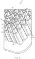
FIGS. 3-8 , an embodiment of an oral care implement 40 according to the present invention is shown. The oral care implement 40 comprises abase 100 and a plurality ofelements 50 extending from thebase 100. Theelements 50 comprise aproximal end 54 connected to thebase 100 and adistal end 52 opposite the proximal end. As shown, theelements 50 may comprise four segments: afirst segment 60 at thedistal end 52; asecond segment 70 disposed at an end of thefirst segment 60 opposite thedistal end 52; athird segment 80 disposed at an end of thesecond segment 70 opposite the first segment; and afourth segment 90 disposed at an end of thethird segment 80 opposite the second segment. In is understood that theelements 50 may comprise any number of segment, including but not limited to one, two, three, or any other number. The segments may be fabricated such that the segments are integral to each other such as, for example integrally formed using a plastic injection molding process. In another embodiment, each segment may be fabricated as separate components that then are attached to adjacent segments using conventional connection techniques or devices, including but not limited to welding, adhesives, snap-fit connections, etc. - In the embodiment shown, the
base 100 and the plurality ofelements 50 are fabricated as one integrated unit to form, at least in part, the oral care implement 40. It is understood that thebase 100 and the plurality ofelements 50 may he two separate components that are connected together using conventional techniques and methods of connection such as, for example, adhesives, knotting, sonic welding, etc. - Referring particularly to
FIGS. 4, 5 , and6 , theelements 50 in this embodiment comprise a triangular-shaped transverse cross section. As such, thefirst segment 60 comprises atransverse surface 61, threelongitudinal surfaces 63, atransverse edge 66, a firstlongitudinal edge 68a, secondlongitudinal edge 68b, and a thirdlongitudinal edge 68c. Additionally, thesecond segment 70 comprises atransverse surface 71, threelongitudinal surfaces 73, atransverse edge 76, a firstlongitudinal edge 78a, secondlongitudinal edge 78b, and a thirdlongitudinal edge 78c. Also, thethird segment 80 comprises atransverse surface 81, threelongitudinal surfaces 83, atransverse edge 86, a firstlongitudinal edge 88a, secondlongitudinal edge 88b, and a thirdlongitudinal edge 88c. Also, thefourth segment 90 comprises atransverse surface 91, threelongitudinal surfaces 93, atransverse edge 96, a firstlongitudinal edge 98a, secondlongitudinal edge 98b, and a thirdlongitudinal edge 98c. -
FIG. 7 shows thetransverse edge 66 having a tip radius (r). The transverse edges 76, 86, and 96 may also comprise a tip radius as shown and measured inFIG. 7 . In one embodiment, theelement 50 may include one or moretransverse edges element 50 may include one or moretransverse edges U.S. Pat. Pub. No. 2009/0007357 . -
FIG. 8 shows thelongitudinal edge 88c having a tip radius (r). Thelongitudinal edges FIG. 8 . - Referring back to
FIG. 5 , theelement 50 comprises a length (L). Length (L) may comprise from about 0.05 mm to about 10 mm, particularly from about 0.1 mm to about 8 mm, more particularly from about 1.0 mm to about 7 mm, or more particularly from about 2.0 nun to about 6 mm. In one embodiment, the length (L) of theelement 50 may comprise about 4 mm. Each of the first, second, third, andfourth segments first segment 60 may have a first segment width (W1) from about 0.06 to about 1.0 mm, a segment width (W2) from about 0.07 mm to about 2.0 mm, a third segment width (W3) from about 0.09 mm to about 3.0 mm, and a fourth width (W4) from 0.1 mm to about 4.0 mm. - One or more of the
longitudinal surfaces FIG. 5 ). The angle a may less than about 30 degrees, particularly less than about 20 degrees, more particularly less than about 15 degrees, more particularly less than about 10 degrees, even more particularly less than about 5 degrees, and/or from about 0 degrees to about 90 degrees, from about 15 degrees to about 75 degrees, particularly from about 30 degrees to about 60 degrees, more particularly from about 0 degrees to about 45 degrees, even more particularly from about 0 degrees to about 30 degrees, even more particularly from about 0 degrees to about 15 degrees, even still more particularly from about 0 degrees to about 10 degrees, or even still more particularly about 1.5 degrees. - The oral care implement 40 may comprise an element density of the plurality of
elements 50, which comprises the spacing between eachadjacent element 50. As such, the element density may be measured by measuring the distance (d) between a center point of oneelement 50 to a center point of anadjacent element 50. Thebase 100 and the plurality ofelements 50 may be fabricated such that theelements 50 are equally spaced from each other. In another embodiment, thebase 100 and the plurality ofelements 50 may be fabricated such that the individual elements are unequally separated from each other along thebase 100. In such an embodiment, the element density is an average of the measured distances between eachelement 50. In one embodiment, thebase 100 has an element density from 0.09 mm to about 0.4 mm, more particularly from about 0.1 mm to about 3.0 mm, or more particularly from about 0.2 nun to about 2 mm. - Referring to
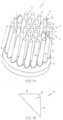
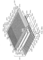
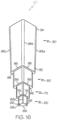
FIGS. 9-11 , another embodiment of an element for an oral care implement according to the present invention (not shown but may be the same as or similar to those oral care implements shown and described herein, e.g., oral care implements 1, 40) is shown as 150. Theelement 150 may aproximal end 154 and adistal end 152 opposite of theproximal end 154. As in other embodiments shown and described herein, theelement 150 may extend from a base (not shown), wherein theproximal end 154 is integral with or connected to the base. As also in the other embodiments, a plurality ofelements 150 may extend from the base to form, in part, an oral care implement. - As shown, the
element 150 may comprise three segments: afirst segment 160 at thedistal end 152; asecond segment 170 disposed at an end of thefirst segment 160 opposite thedistal end 152; athird segment 180 disposed at an end of thesecond segment 170 opposite thefirst segment 160. As set forth above with reference to the other embodiments, theelement 150 may comprise any number of segment, each having any number of shapes, sizes, and configurations. As with the element's connection with the base, the segments (e.g., first, second, andthird segment - The
first segment 160 may comprise a star-shaped transverse cross section as shown inFIGS. 9 and 11 . Thefirst segment 160 comprises a transverse surface 166, tenlongitudinal surfaces 163, tentransverse edges 166a-j (traversing about the longitudinal axis A-A' of the first segment in a counter clockwise direction), and tenlongitudinal edge 168a-j (traversing about the longitudinal axis A-A' of the first segment in a counter clockwise direction). Thesecond segment 170 may comprise a square-shaped transverse cross section. Thesecond segment 170 comprises atransverse surface 171, fourlongitudinal surfaces 173, fourtransverse edges 176a-d (traversing about the longitudinal axis A-A' of the second segment in a counterclockwise direction), and four longitudinal edges 178a-d. Thethird segment 180 may comprise a cross-shaped transverse cross section. Thethird segment 180 comprises atransverse surface 181, twelvelongitudinal surfaces 183, twelve transverse edges 186a-l (traversing about the longitudinal axis A-A' of the third segment in a counter clockwise direction), and eightlongitudinal edges 188a-h. Thetransverse edges 166a-j, 176a-d, and 186a-l andlongitudinal edges 168a-e, 178a-d, and 188a-h of implement 150 may comprise a tip radius (r) such as, for example, the tip radius shown and measured inFIGS. 7 and 8 . - In the embodiment shown in
FIGS. 9-11 , thefirst segment 160,second segment 170, andthird segment 180, each have a transverse cross sectional area that is different from the other segments' transverse cross sectional area. Specifically, the first segment's transverse cross section area is smaller than the second and third segments' transverse cross sectional areas, and the second segment's transverse cross sectional area is smaller than the third segment's transverse cross sectional area, giving the element 150 a tiered configuration. It is also understood that the longitudinal edges of the first, second, and/or third segments may be oriented at any angle (e.g., angle α as shown inFIG. 5 ) relative to the longitudinal axis. The angle α may less than about 30 degrees, particularly less than about 20 degrees, more particularly less than about 15 degrees, more particularly less than about 10 degrees, even more particularly less than about 5 degrees, and/or from about 0 degrees to about 90 degrees, from about 15 degrees to about 75 degrees, particularly from about 30 degrees to about 60 degrees, more particularly from about 0 degrees to about 45 degrees, even more particularly from about 0 degrees to about 30 degrees, even more particularly from about 0 degrees to about 15 degrees, even still more particularly from about 0 degrees to about 10 degrees, or even still more particularly about 0 degrees. - Referring to
FIG. 10 , theelement 150 comprises a length (L). Length (L) may comprise from about 0.5 mm to about 10 mm, particularly from about 1.0 mm to about 8 mm, more particularly from about 2.0 mm to about 7 mm, or more particularly from about 3.0 mm to about 6 mm. In one embodiment, the length (L) of theelement 150 may comprise about 4 mm. Each of the first, second, andthird segments first segment 60 may have a first segment width (W1) from about 0.06 mm to about 1.0 mm, a segment width (W2) from about 0.07 mm to about 2.0 mm, and a third segment width (W3) from about 0.09 mm to about 3.0 mm. The width as used herein may comprise the longest dimension along the transverse cross section. As with the length, the segments ofelement 150 may comprise any width as desired. - The oral care implement may comprise an implement density of the plurality of
elements 150, which comprises the spacing between eachadjacent element 150. As such, the element density may be measured by measuring the distance between a center point of oneelement 150 to a center point of anadjacent element 150. The base and the plurality ofelements 150 may be fabricated such that theelements 150 are equally spaced from each other. In another embodiment, the base and the plurality ofelements 150 may be fabricated such that the individual elements are unequally separated from each other along the base. In such an embodiment, the element density is an average of the measured distances between eachelement 150. In one embodiment, the base has an element density from 0.09 mm to about 0.4 mm, more particularly from about 0.1 mm to about 3.0 mm, or more particularly from about 0.2 mm to about 2 mm. - In one embodiment, one or more of the transverse edges (e.g.,
transverse edges 166a-j, 176a-d, and 186a-l of theelement 150 may comprise a micro edge. In another embodiment, one or more of thelongitudinal edges 168a-e, 178a-d, and 188ah ofelement 150 may comprise a micro edge. In yet another embodiment, theelement 150 may comprise thetransverse edges 166a-j, 176a-d, and 186a-l andlongitudinal edges 168a-e, 178a-d, and 188a-h, wherein at least one of the traverse edges and at least one of the longitudinal edges are micro edges, edges, or combinations thereof. - An oral care implement (e.g., oral care implement 1 of
FIG. 1 ) may comprise a plurality of element such as, for example,element 150, or a combination of elements such as, for example,elements 50, or other conventional or yet-to-be developed elements. The several examples of the elements (e.g., 10, 50, 150, 2050) and bases (e.g., 20, 100, 2100) shown and described herein may be fabricated from a variety of materials, particularly materials used for oral care applications such as, for example materials used for oral care bristles, flexible elements, etc. In one embodiment, the elements (e.g., 10, 50, 150, 2050) are fabricated from a compliant material for enhanced cleaning with reduced abrasion. The bases (e.g., 20, 100, 2100) may be fabricated from the same or different material as the elements depending upon the properties desired. Also, the material used for the fabrication of the elements and/or the bases may be a single substrate material, composite material, multi-laminate structure, or any combination thereof. - In one or more of the embodiments shown and described herein, the material used for the elements (e.g., 10, 50, 150, 2050) and/or bases (e.g., 20, 100, 2100) may comprise a flexible (or compliant) material, including but not limited to thermoplastic elastomers, rubber, flexible composites, and combinations thereof. In an embodiment, one or more of the plurality of elements (e.g., 10, 50, 150, 2050) and/or bases (e.g., 20, 100, 2100) may be formed of a thermoplastic or a cross-linked material (a thermoset material).
- Examples of suitable elastomeric materials include one or more styrenic copolymers, thermoplastic polyurethanes, silicones, polyether-amides, polyether-polyesters, or mixtures of these and other elastomers. Any elastomeric material described herein can include one or more fillers. For example, the filler may be or may include oil, e.g., mineral oils, abrasives, tackifiers, plasticizers or mixtures of these and even others. As an example, the material that may be used for one or more of the plurality of element (e.g., 10, 50, 150, 2050) and/or bases (e.g., 20, 100, 2100) may comprise a flexible material having a Shore Hardness of from about 8 Shore A to about 75 Shore D, as a further example, from about 35 Shore A to about 55 Shore D.
- Not to be limited by theory, the material hardness is believed to be highly correlated with and may be used to specify the desired stiffness/flexibility of the cleaning element(s) in order to manipulate how the cleaning element(s) will move (e.g., twisting, bending, and/or other deformation) and how significant this motion will be due to a driving motion provided to the oral care implement. Elastomeric materials enable the element(s) (e.g.,
elements FIGS. 24A-F ). As set forth herein, the material used for the elements may be flexible enough to twist, bend, and deform in order to permit one or more elements to contact the teeth. However, in certain embodiments, if the element is too flexible, it will lack the rigidity, particularly its edges, to effectively, if at all, remove plaque and debris from the oral cavity surfaces. Thus, in some embodiments, the hardness of the material may also be configured in order that the stiffness/flexibility of the element(s) is sufficient and/or adequate enough that the cleaning edge (e.g., transverse and/or longitudinal edges) of the element is able overcome the plaque or debris' adhesion to the tooth's surface. Thus, some of the embodiments shown and described herein provide such a balance between the two competing factors. - In one embodiment, the material may comprise a thermoplastic elastomer, including but not limited to Pellethane 2363, which is commercially available from Dow Chemical Company, 4520 Ashman Street, Midland, Michigan 48642. In another embodiment, the compliant and/or flexible material used for the elements and/or base may have the following material properties: a hardness (durometer) from about 55 Shore A to about 55 Shore D; wet friction greater than about 0.05, particularly greater than about 0.1, more particularly greater than or equal to about 0.5 in order to create friction in the wet oral environment that may be sufficient enough such that the element edges engage the adhesion boundary between the plaque and the surface of the tooth, rather than slide over the surface of the plaque; surface pressure (contact angle) greater than about 500 Nm-1 x 10⁴, more particularly greater than about 600 Nm-1 x 10⁴, even more particularly greater than about 700 Nm-1 x 10⁴, even more particularly about 727 Nm-1 x 10⁴; and density from about 0.05 g/cm3 to about 3.0 g/cm3, from about 0.5 g/cm3 to about 2.0 g/cm3, more particularly 0.9 g/cm3 to about 1.2 g/cm3. One or more of the embodiments of the cleaning implement and its plurality of elements shown and described herein are configured such that the dislodged plaque and debris can be transported from the cleaning site with the aid of surface wetting and/or capillary action of the saliva, water and/or dentifrice/plaque/debris suspension or slurry.
- In one embodiment, the elements (e.g.,
element - The plurality of elements (e.g.,
elements - Referring to
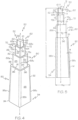
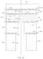
FIGS. 12-14 , an embodiment of a plasticinjection mold system 220 is shown for illustration purposes only, and not limitation, in conjunction with a plasticinjection mold machine 200 for molding one ormore elements 50 and/or a base (e.g., base 100). The plasticinjection mold system 220 may comprise one or more cavity mold plates. In one embodiment, the plasticinjection mold system 220 comprises a firstcavity mold plate 230, a secondcavity mold plate 240, a thirdcavity mold plate 250, and a fourthcavity mold plate 260. The first, second, third, and fourthcavity mold plates mold cavities fourth segments elements 50. In other words, when the four cavity mold plates (e.g., 230, 240, 250, 260) are assembled together their respective mold cavities (e.g., 232, 242, 252, 262) form the mold cavities for molding the plurality ofelements 50 having segments (e.g.,segments mold cavities - As shown, since the desired transverse cross sectional shape of each of the segments of the
element 50 are triangular-shaped, the respective mold cavities are each triangular-shaped. The plurality ofmold cavities segments mold system 220, i.e., the assembled fourcavity mold plates injection mold machine 200. In this embodiment, the plasticinjection mold machine 200 may comprise any variety of conventional plastic injection mold machines that are commercially available. The plasticinjection mold machine 200 may comprise a cavityside mold plate 202 and a coreside mold plate 203. The coreside mold plate 203 may comprise anouter core module 204 and aninner core module 206. - As shown in
FIG. 12 , the firstcavity mold plate 230 has first and second plate surfaces 231 and 233, respectively. Similarly, the secondcavity mold plate 240 has first and second plate surfaces 241 and 243, respectively, and the thirdcavity mold plate 250 has first and second plate surfaces 251 and 253, respectively. The fourth cavity mold plate may include afirst plate surface 263. When the cavity mold plates are assembled together in a transverse abutting configuration as shown inFIGS. 12 and14 , each pair of abutting, transverse mold cavity plates form a transverse intersection. For example, when thefirst plate surface 231 of firstmold cavity plate 230 is abutted against thesecond plate surface 243 of the secondmold cavity plate 240, a secondtransverse intersection 245 is formed as shown inFIG. 14 . Similarly,FIG. 14 shows a thirdtransverse intersection 255 is formed at the abutment of thefirst plate surface 241 of the secondmold cavity plate 240 with thesecond plate surface 253 of the thirdmold cavity plate 250, and a fourthtransverse intersection 265 is formed at the abutment of thefirst plate surface 251 of the thirdmold cavity plate 250 with thesecond plate surface 263 of the fourthmold cavity plate 260. Additionally, a firsttransverse intersection 235 may be formed between or at the abutment of thesecond plate surface 233 with a surface of the cavity side mold plate 202 (FIG. 14 ). - Not to be limited by theory, it is believed that as the plastic is injected into the plurality of mold cavities (e.g., the plurality of assembled
mold cavities mold cavity plates transverse intersections mold cavity plates FIG. 14 are exaggerated for clarity purposes and not meant to be to scale or for limitation. - As shown in
FIG. 14 and set forth above, the gas may exit and/or out-gas at thetransverse intersections transverse intersections FIGS. 13 and14 , themold system 220 forms transverseedges transverse intersections - Moreover, as set forth above, the conventional plastic injection mold processes and mold systems, including but not limited to those shown and described within
U.S. Pat. Pub. No. 2009/0007357 , cannot form and/or fabricate the micro edges as shown and defined herein. AlthoughU.S. Pat. Pub. No. 2009/0007357 describes its plastic injection mold process and mold systems as forming sharp edges on flexible elements, it has been unexpectedly found that the mold system fabricates micro edges shown and described herein that include a tip radius that is a whole order of magnitude smaller than the tip radii of the sharp edges shown and described inU.S. Pat. Pub. No. 2009/0007357 . - In order to form micro edges along the
longitudinal edges 68a-c, 78a-c, 88a-c, and/or 98a-c, one or more of thecavity mold plates FIGS. 15 and16 , another embodiment of a plasticinjection mold system 220 is shown. The plasticinjection mold system 220 comprises a firstcavity mold plate 230, a secondcavity mold plate 240, a thirdcavity mold plate 250, and a fourthcavity mold plate 260. In this embodiment, the firstcavity mold plate 230 may comprise a plurality of longitudinalcavity mold plates 230a-230t, wherein each longitudinalcavity mold plate 230a-t comprises two longitudinal plate surfaces such as, for example, a firstlongitudinal plate surface 231a and a secondlongitudinal plate surface 233a of first longitudinalcavity mold plate 230a and a firstlongitudinal plate surface 231 b and a secondlongitudinal plate surface 233b of second longitudinalcavity mold plate 230b. When the secondlongitudinal plate surface 233a abuts the firstlongitudinal plate surface 231b as shown inFIG. 15A , this intersection forms alongitudinal intersection 236. (See alsoFIG. 15B ). Each consecutive longitudinal mold plate has similar first and second longitudinal plate surfaces forming their respectivelongitudinal intersections 236 as shown and described for the first longitudinalcavity mold plate 230a. In addition, each longitudinalcavity mold plate 230a-t forms a row of mold cavities to mold thefirst segments 60 of the plurality ofelements 50. - The fourth
cavity mold plate 260 also comprises a plurality of longitudinalcavity mold plates 260a-t, wherein each longitudinalcavity mold plate 260a-t comprises two longitudinal plate surfaces such as, for example, a firstlongitudinal plate surface 261a and a second longitudinal plate surface (263a) of first longitudinalcavity mold plate 260a and a firstlongitudinal plate surface 261b and a second longitudinal plate surface (263b) of secondlongitudinal plate surface 260b. When the secondlongitudinal plate surface 263a abuts the firstlongitudinal plate surface 261b as shown inFIGS. 15A and15B , this intersection forms alongitudinal intersection 266. Each consecutive longitudinal mold plate has similar first and second longitudinal plate surfaces forming their respectivelongitudinal intersections 266 as shown and described for the first longitudinalcavity mold plate 260a. Also, a first and second longitudinalend mold plates longitudinal intersections 266 with longitudinalcavity mold plate FIG. 15A . In addition, each longitudinalcavity mold plate 260a-t forms a row ofmold cavities 262 to mold thefourth segments 90 of the plurality ofelements 50. In this embodiment, the second and thirdcavity mold plates mold cavities third segments - The first longitudinal
cavity mold plates 230a-t, secondcavity mold plate 240, third cavity mold plate, and fourth longitudinalcavity mold plates 260a-t may be assembled together and positioned within a conventional plastic injection mold machine (e.g., plasticinjection mold machine 200 shown inFIG. 12 ). When assembled together, the first longitudinalcavity mold plates 230a-t, secondcavity mold plate 240, third cavity mold plate, and fourth longitudinalcavity mold plates 260a-t form respective transverse intersections. For example, the first longitudinalcavity mold plates 230a-t as an assembly form a firsttransverse intersection 235 between the cavityside mold plate 202 and theplates 230a-t themselves. At the abutment of the first longitudinalcavity mold plates 230a-t with the secondcavity mold plate 240, a secondtransverse intersection 245 is formed. The abutment of the secondcavity mold plate 240 and the thirdcavity mold plate 250 forms a thirdtransverse intersection 255. Also, the abutment of the third cavity mold plate 250with the fourthcavity mold plates 260a-t forms a fourthtransverse intersection 265. Once thecavity mold plates 230a-t, 240, 250, and 260 are assembled together to form themold system 220, themold system 220 may be disposed within and connected to a conventional plastic injection mold machine (e.g., similar to or the same asmold machine 200 shown inFIG. 12 ). Although not shown, mold machine will comprise a cavity side mold plate (e.g., cavityside mold plate 202 inFIG. 12 ) having a first surface. - Not to be limited by theory, it is believed that as the plastic is injected into the plurality of mold cavities (e.g., the plurality of assembled
mold cavities cavity mold plates 230a-t, 240, 250, and/or 260a-t at and along any intersection between the mold plates (i.e., through the spaces between these plates) such as, for example,longitudinal intersections transverse intersections mold cavity corners FIG. 15B ). In so doing, the plastic injection molding process is able to form micro edges at and along any intersection, both transverse and longitudinal, between any two molding plates and/or between any mold plate and the cavityside mold plate 202. - Still referring to
FIGS. 15 and16 , themold system 220 forms transverseedges elements 50 as micro edges using the respectivetransverse intersections mold system 220 formslongitudinal edges elements 50 as micro edges using the respectivelongitudinal intersections cavity mold plates 230a-t and 260a-t. In this embodiment, micro edges (e.g., transverse and/or longitudinal micro edges) cannot be formed using a plastic extrusion process as used to form conventional bristles and flexible elements, particularly those used for oral care devices. - As set forth above, this
mold system 220 may be inserted into and connected to a conventional plastic injection molding machine. As configured in thismold system 220, it is understood that if additional longitudinal edges were desired, both the second and thirdcavity mold plates cavity mold plates 230a-t and 260a-t, respectively. - Referring to
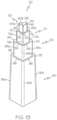
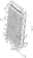
FIGS. 17-19 , another embodiment of a plasticinjection mold system 520 is shown to form a plurality ofelements 155.FIG. 18 illustrates one ofelement 155 that the plurality of elements may comprise. The plasticinjection mold system 520 comprises a first cavitymold plate assembly 530 to form afirst segment 60 of theelement 155 using a plurality of mold cavities 542a-t, 552a-t, 562a-t, 572a-t, 582a-t, 592a-t, 602a-t, 612a-t, 622a-t, 632a-t, 642a-t, 652a-t, 662a-t, 672a-t, 682a-t, 692a-t, 702a-t, 712a-t, 722a-t, and 732a-t and a second cavity mold plate (not shown) to form asecond segment 70 of theelement 155 using a plurality of mold cavities (not shown). For simplicity and clarity purposes,FIGS. 17 ,19A , and19B only show the first cavitymold plate assembly 530 of themold system 520. In addition,FIGS. 17 ,19A , and19B show a cavityside mold plate 202 of a conventional plastic injection molding machine (e.g.,machine 200 as shown inFIG. 12 ) in order to illustrate the engagement and connection of the first cavitymold plate assembly 530 with and to such cavityside mold plate 202. - As shown and described in the embodiments set forth above herein, the first cavity
mold plate assembly 530 and the cavityside mold plate 202 may form a first transverse intersection 535 as shown inFIG. 19B . Additionally, not to be limited by theory, the first transverse intersection 535 may form a micro edge alongtransverse edge 66 of theelement 155 shown inFIG. 18 due to the gas exiting and/or out-gassing from the plurality of mold cavities as the transverse intersection 535 as shown and described above herein with respect to the embodiments. Similarly, not to be limited by theory, a second transverse intersection (not shown) may be formed between the first cavitymold plate assembly 530 and the second cavity mold plate (not shown) to form a micro edge alongtransverse edge 76 ofelement 155 as shown inFIG. 18 due to the gas exiting and/or out-gassing from the plurality of mold cavities as the transverse intersection as shown and described above herein with respect to the embodiments. It should be understood that second transverse intersections may be removed by the first andsecond segments transverse edge 76. - As shown in
FIGS. 17 ,19A , and19B , the first cavitymold plate assembly 530 may comprise a plurality of individual cavity mold plates (e.g., cavity mold plates 540at, 550a-t, 560a-t, 570a-t, 580a-t, 590a-t, 600a-t, 610a-t, 620a-t, 630a-t, 640a-t, 650a-t, 660a-t, 670a-t, 680at, 690a-t, 700a-t, 710a-t, 720a-t, and 730a-t), a plurality ofplate separators 547a-t, and a plurality ofend plates 740a-t. The cavity mold plates and plate separators form a plurality of mold cavities. For example, the cavity mold plates 540at andplate separator 547a form a plurality of mold cavities 542a-t, thecavity mold plates 550a-t andplate separator 547b form a plurality of mold cavities 552a-t, thecavity mold plates 560a-t andplate separator 547c form a plurality of mold cavities 562a-t, and so on through thecavity mold plates 730a-t, wherein thecavity mold plates 730a-t andplate separator 547t form a plurality ofmold cavities 732a-t. - When assembled, the cavity mold plates (e.g.,
cavity mold plates 540a-t, 550at, 560a-t, 570a-t, 580a-t, 590a-t, 600a-t, 610a-t, 620a-t, 630a-t, 640a-t, 650a-t, 660a-t, 670a-t, 680a-t, 690a-t, 700a-t, 710a-t, 720a-t, and 730a-t) and theplate separators 547a-t form a plurality of first and second longitudinal intersections between these cavity mold plates and the plate separators. As examples, a firstlongitudinal intersection 737a is formed betweencavity mold plate 730a andplate separator 547t, and a secondlongitudinal intersection 736a may be formed between the cavity mold plate 730b andplate separator 547t as shown inFIG. 19B . Not to be limited by theory, these two longitudinal intersections may form micro edges alonglongitudinal edges mold cavity 732a due to the gas exiting and/or out-gassing through the respective intersections during the plastic injection molding process. As another example, a firstlongitudinal intersection 737e may be formed betweencavity mold plate 730c andplate separator 547t, and a secondlongitudinal intersection 736e may be formed between the cavity mold plate 730f andplate separator 547t as shown inFIGS. 17 ,19A , and19B . Again, not to be limited by theory, these two longitudinal intersections may form micro edges alonglongitudinal edges - A plurality of third longitudinal intersections may be formed between (i.e., the abutment of) adjacent
cavity mold plates 540a-t, 550a-t, 560a-t, 570a-t, 580a-t, 590at, 600a-t, 610a-t, 620at, 630a-t, 640a-t, 650a-t, 660a-t, 670a-t, 680a-t, 690a-t, 700a-t, 710a-t, 720a-t, and 730a-t. As an example, a third longitudinal intersection 735a may be formed between adjacentcavity mold plates 730a and 730b. Again, not to be limited by theory, this third longitudinal intersection 735a may form a micro edge along thelongitudinal edge 68a ofmold cavity 732a due to the gas exiting and/or out-gassing through this intersection during the plastic injection molding process. As another example, another third longitudinal intersection may be formed between adjacentcavity mold plates 730e and 730f. Moreover, not to be limited by theory, this third longitudinal intersection 735e may form a micro edge along thelongitudinal edge 68a of mold cavity 732e due to the gas exiting and/or out-gassing through this intersection during the plastic injection molding process. - With this configuration, each of the plurality of mold cavities 542a-t, 552a-t, 562a-t, 572a-t, 582a-t, 592a-t, 602a-t, 612a-t, 622a-t, 632a-t, 642a-t, 652a-t, 662a-t, 672a-t, 682a-t, 692a-t, 702a-t, 712a-t, 722a-t, and 732a-t may form a segment of an
element 155 having three longitudinal intersections (e.g., 735e, 736c, and 737c) that permit the formation of threelongitudinal edges cavity mold plate 540a-t, 550a-t, 560at, 570a-t, 580a-t, 590a-t, 600a-t, 610a-t, 620a-t, 630a-t, 640a-t, 650a-t, 660a-t, 670a-t, 680a-t, 690a-t, 700a-t, 710a-t, 720a-t, and 730a-t with aplate separator 547a-t and between each and every adjacent cavity mold plate as shown inFIGS. 17 and19 . - In the embodiment shown in
FIGS. 17-19 , when the gas exits/out-gases from the mold cavities at and along these transverse and longitudinal intersections between the cavity mold plates, the gas pushes and/or draws the plastic deep into the corners. In so doing, the molding process of this mold system is able to form micro edges at and along any intersection, both transverse and longitudinal, between two cavity mold plates and/or assemblies, cavity mold plates/assemblies and plate separators, adjacent mold plates, cavity mold plates/assemblies and mold machine surfaces (e.g., cavity side mold plate 202), and/or any combinations thereof. - It is understood that if additional longitudinal edges were desired on both
segments transverse edges longitudinal edges element 50 by adding or subtracting the number of cavity mold plate layers, i.e., if four segments desired, themold system 520 will include four cavity mold plates. It is also understood that each cavity mold plate layer may comprise the individual cavity mold plates, plate separators, and other components as shown and described above here as well as other relevant modifications. In addition, although a triangular-shaped transverse cross section was shown in the embodiments shown and described above, any transverse cross sectional shape may be used, including different transverse cross sectional shapes for each segment of an element. - Referring to
FIGS. 20 and21 , another embodiment of aplastic mold system 1020 andelements 1050 that may be molded using suchplastic mold system 1020 are shown. The several embodiments of themold system 1020 may be used with a conventional plastic injection mold machine as shown and described above herein and known to one of ordinary skill in the art (e.g.,mold machine 200 shown inFIG. 12 ). In one embodiment, themold system 1020 may comprise a plurality of cavity mold plates (e.g.,cavity mold plates cavity mold plates FIGS. 12-14 . In the configuration shown inFIGS. 20 and21 , themold system 1020 would form longitudinal intersections (e.g.,longitudinal intersections cavity mold plates FIG. 20 , themold plates elements 1050 using a plurality ofmold cavities 1082. - As shown in
FIG. 20 ,elements 1050 each compriselongitudinal edges FIG. 21 , thelongitudinal edge 1068a is formed by aninternal corner 1083a of themold cavity 1082. Thus, not to be limited by theory, thelongitudinal edge 1068a may not be a micro edge as defined herein because the gas within themold cavity 1082 may not exit and/or out-gas through thisinternal corner 1083a because this corner does not comprise an intersection between to mold plates. Thelongitudinal edge 1068a may comprise a non-out-gassed edge. A "non-out-gassed" edge is an edge of the flexible element that is formed within a single cavity mold plate, i.e., an internal corner within a single mold plate and thus an edge not formed along an intersection of two molding plates, used in a molding process such as plastic injection molding. In other words, a non-out-gassed edge is an edge formed without using out-gassing between and through the intersection of two molding plates. In contrast, thelongitudinal edges mold cavity corners cavity mold plate 1080 and adjacent cavity mold plate (not shown). Thus, thelongitudinal edges - In one embodiment, a molding cycle for a plurality of cleaning elements and a base unit fabricated from a Pellethane 2363 resin comprises a barrel temperature of from about 380 degrees F (193 degrees C) to about 410 degrees F (210 degrees C), a mold temperature of from about 60 degrees F (15 degrees C) to about 140 degrees F (60 degrees C), and an injection pressure of from about 1600 bar to about 1800 bar.
- Referring to
FIG. 22 , an embodiment of anoral care system 2000 is shown, which may comprise an oral care implement 2001 having abase 2100, a plurality of flexible,elastomeric elements 2050 extending from thebase 2100, and a drive system operable to drive, move, and/or push the plurality of flexible,elastomeric elements 2050 and/or thebase 2100 such that the plurality ofelements 2050 engageteeth 2020 and/orgums 2010 disposed within an oral cavity (e.g., a human mouth). In one embodiment, the plurality ofelements 2050, thebase 2100, and at least a portion of the drive system is configured to insert into an oral cavity and be positionedadjacent teeth 2020 andgums 2010 of the oral cavity. Theoral care system 2000 may further comprise ahousing 2120. Thebase 2100 and plurality ofelements 2050 may comprise any of the embodiments shown and described above herein. - As shown in
FIG. 22 , the drive system may comprisebladder 2110 positioned on a side of thebase 2100 opposite the plurality ofelements 2050. Thebladder 2110 may comprise areservoir 2112 for receiving a fluid and be flexible such that the bladder may expand and contract in response to fluid filling or emptying from thereservoir 2112. Examples of the flexible materials that the bladder may be fabricated from may include, but not be limited to natural rubber and other sulfur vulcanizable rubbers such as butyl, nitrile, styrene-butediene, saturated rubbers such as silicone, ethylene propylene and epichlorohydrin and thermoplastic elastomers such as polyurethane, polyolefin and styrenic block copolymers. The drive system may also comprise apump 2130 for supplying a fluid from a fluid source (not shown), aconduit 2114 connecting thepump 2130 to thebladder 2110, and/or amotor 2140 for driving the pump. Thepump 2130,conduit 2114, andmotor 2140 may comprise any conventional or yet-to-be developed pumps, conduits, and/or motors, particularly such devices that are used for oral care systems. Theconduit 2114 may comprise rigid or semi rigid piping or flexible hosing as known to one of ordinary skill in the art. - The
oral care system 2000 may pump a variety of known or yet-to-be developed fluids into thebladder 2110 from the fluid source, including but not limited to water, air, gases, any combinations thereof, and other fluids operable to drive the bladder. The source may be a reservoir, the atmosphere, compressed gas tank, or any other conventional fluid supply. Themotor 2140 may be a conventional or yet-to-be developed motor, including but not limited to an electric (both D/C-powered or A/C-powered), magnetic, fuel-powered, manually-powered, electro-chemical, or combinations thereof. - The
oral care system 2000 may comprise ahousing 2120 that is connected to or integral to thebase 2100. In this embodiment, thebladder 2110 is at least partially encompassed by thebase 2100 and thehousing 2120. Thehousing 2120 may be fabricated from a semi-rigid or rigid material in order to provide a sturdy structure such that when thebladder 2110 expands due to thereservoir 2112 filling with fluid, the bladder is forced to expand in the direction shown by arrows (A). Examples of the materials used to fabricate thehousing 2120 may include, but not be limited to plastics, metals, composites, and combinations thereof. Examples of the plastics that may be used for the housing may include, but not be limited to polyacete polyolefin, polyamide and polyvinylchloride. As thebladder 2110 expands in direction (A) it causes theelements 2050 to engage theteeth 2020 and gums 2010 ("Impact"). The drive system may be reversed as well to cause thebase 2100 and/or theelements 2050 to move away from theteeth 2020 andgums 2010 as illustrated by arrows (B). As such, thepump 2130 may draw the fluid from thereservoir 2112 of thebladder 2110, causing thebladder 2110 to contract and thus cause theelements 2050 to move away from theteeth 2020 and gums 2010 ("Lift-off'). Thebladder 2110 may comprise a pressure from about 0 kPa to about 60 kPa, particularly from about 10 kPa to about 40 kPa, or more particularly about 20 kPa. Also, the pressure the elements apply to theteeth 2020 andgums 2010 may comprise from about 0 kPa to about 60 kPa, particularly from about 10 kPa to about 40 kPa, or more particularly about 20 kPa. - The drive system may be connected to a controller such as a micro-controller or microprocessor. This controller may be operable to control the motor and/or pump and thus the pumping of fluid into and out of the
bladder 2110, causing a reciprocating action of the plurality ofelements 2050 against and away from the teeth as illustrated by arrows (A and B). The frequency of the reciprocation of thebladder 2110 and thus the elements 2050 (e.g., between Lift-off and Impact) may be from about 1 Hz to about 100 Hz, more particularly from about 50 Hz to about 90 Hz, more particularly from about 65 Hz to about 75 Hz, or more particularly about 70 Hz. In one embodiment, the plurality ofelements 2050 may be moved away from theteeth 2020 and gums 2010 ("Lift off') a distance from about 0 mm to about 10 mm, particularly from about 0 mm to about 8 mm, particularly from about 3 mm to about 7 mm, particularly from about 4 mm to about 6 mm, or more particularly from about 0 mm to about 5 mm. Also, theimplements 2050 may be driven back toward theteeth 2020 and gums 2010 ("Impact") a distance from theteeth 2020 and gums 2010 ("Lift off') a distance from about 0 mm to about 10 mm, particularly from Hz about 0 mm to about 8 mm, particularly from about 3 mm to about 7 mm, particularly from about 4 mm to about 6 mm, or more particularly from about 0 mm to about 5 mm. - In another embodiment, the drive mechanism may comprise more than one of the
bladder 2110, particularly if desired to driveelements 2050 in different directions. In yet another embodiment, the driving mechanism may cause the plurality ofelements 2050 to move along theteeth 2020 andgums 2010 as illustrated by arrows (C), i.e., into and out of the figure and (D), i.e., transverse to arrow (C). Theoral care system 2000 and one or more drive systems may cause theelements 2050 to move or oscillate in one or more of the directions along arrows (C) and/or (D) a distance from about 0 mm to about 10 mm, particularly from about 0 mm to about 6 mm, or particularly from about 0 mm to about 4 mm. Instead of a fluid pump and bladder, the drive mechanism may comprise a variety of other conventional and yet-to-be developed drive and/or actuation systems, including but not limited to ultrasonic drives, vibrating drives, oscillating drives, electric motors, piezoelectric, electrostrictive, electromagnetic, magnetostrictive, acoustostrictive, photostrictive and/or chemostrictive actuators. - In another embodiment, an oral care implement 3001 shown in
FIG. 23 may comprise ahousing 3120 having a firstflexible base 3100a connected to thehousing 3120, a first plurality ofelements 3050a extending from the first base, a secondflexible base 3100b connected to thehousing 3120, a second plurality ofelements 3050b extending from the second base, and abladder 3110 having areservoir 3112 therewithin. The oral care implement 3001 is configured to be inserted within an oral cavity and be substantially U-shaped such that the first plurality ofelements 3050a and/orfirst base 3100a substantially conform and/or surround all or some portion ofteeth 3020a and/orgums 3010a disposed along the upper jaw and the second plurality ofelements 3050b and/orsecond base 3100b substantially conform and/or surround all or some portion ofteeth 3020b and/orgums 3010b disposed along the lower jaw simultaneously. In such a configuration, the oral care implement 3001 is operable to clean theteeth 3020a-b and/orgums 3010a-b of the upper and lower jaws simultaneously, sequentially, or any combination thereof. It is understood that the oral care implement 3001 may be combined with any variety of oral care systems, including but not limited to the several embodiments of the oral care systems shown and described herein (e.g., oral care system 2000). - One or more of the embodiments of the oral care systems (e.g., oral care system 2000) may clean oral cavity tissue (i.e., teeth and gums) in a time less than or equal to about 15 seconds/tooth surface, more particularly less than or equal to about 10 seconds/tooth surface, even more particularly less than or equal to about 5 seconds/tooth surface.
- It is also believed, but not intended to be held by theory, that one or more of the embodiments of the oral care systems shown and described herein (e.g., oral care system 2000) and/or oral care implements (e.g., implements 1, 40, 2001) improve interdental (interstitial) cleaning, i.e., cleaning of the teeth and gums disposed between adjacent teeth, compared to conventional oral care cleaning implements and devices. Teeth generally are positioned about 1 Hz mm to about 1.5 mm apart from each other. In one or more of the embodiments shown and described herein, the base (e.g., bases 20, 100, etc.) comprises the plurality of elements spaced (e.g., tip density) such that approximately 6 to 7 elements fit within the space between adjacent teeth (e.g., the approximately 1 mm to 1.5 mm spacing between teeth) thus providing improved interdental cleaning.
- As an example,
FIGS. 24A-F illustrate such oral care implement having flexible cleaning elements that provide improved interdental cleaning due to the elements size (e.g., width, length) and oral care implement's element density as set forth above.FIGS. 24A-F illustrate sequential frames of an array offlexible elements 3050 having a triangular shape, transverse cross-section as they are moved and/or pushed into aninterdental area 3080 between twoteeth distal ends 3052 toward proximal ends 3054 of the plurality of flexible elements are shown inFIGS. 24A and 24D , and isometric views are shown inFIGS. 24B and 24C to illustrate an example of the orientation and position of the flexible,elastomeric elements 3050 with respect to theinterdental area 3080 before and as the plurality offlexible elements 3050 are being moved into and initially engaging the teeth surfaces within theinterdental area 3080. - As set forth above and not to be limited by theory, it is believed that the cross-sectional size and shape, length, and/or material properties (e.g., material hardness, material wetness, etc.) of the flexible element along with the element density of the oral care implement and/or the type of motion used to drive the plurality of elements can be utilized and maximized to improve the twisting, bending, and/or other deformation motion of the flexible elements in order to improve and/or maximize the engagement of the edges, particularly micro edges, and the contact stresses with the surfaces of teeth, particularly with the surfaces within interdental areas.
FIG. 24E-F illustrates, as an example, how such a combination of flexible element and oral care implement properties can affect the contact stresses and contact engagement of the edges and/or surfaces of the flexible elements on teeth. As shown, adjusting and controlling such properties will also impact how the flexible elements twist, bend, and/or deform when one or more of the flexible, elements fully engage the teeth surfaces within theinterdental area 3080. -
FIG. 24F provides an illustrative representation of a view from the distal ends 3052 toward the proximal ends 3054 shown inFIG. 24E with the teeth removed from the view. As shown inFIG. 24F , one or more of the plurality offlexible elements 3050 twist, bend and/or deform such that more than one transverse edge and/or one or more longitudinal edge are caused to engage the teeth surfaces in theinterdental area 3080. It is understood that one or moretransverse edge 3056 and/or one or morelongitudinal edge 3058 may comprise a micro edge as shown and defined herein.FIG. 24E also shows, based upon a finite element analysis, via shading what portion of the flexible elements contact the teeth surfaces within the interdental area. The darker shaded areas show the highest level of contact stress (CPRESS in figure legend) between the element and the tooth's surface due to the movement of the element against the (tooth. As shown, the configuration in this example provides multiple edges contacting the teeth surfaces (contact trace) with increased contact stresses along those edges, thus providing improved interdental cleaning.
Claims (14)
- An oral care implement (40, 2001, 3001) comprising:a base portion (100, 200, 2100) sized for insertion into an oral cavity; anda plurality of flexible, elastomeric elements (50, 150, 155, 2050, 3050) extending from the base portion (100, 200, 2100);wherein at least one of the plurality of flexible, elastomeric elements (50, 150, 155, 2050, 3050) comprisesa first section having a first section edge and a first transverse cross sectional area, anda second section disposed adjacent to the first section along a longitudinal axis of the at least one of the plurality of flexible, elastomeric elements (50, 150, 155, 2050, 3050), the second section having a second section edge and a second transverse cross sectional area different from the first transverse cross sectional area, wherein the first and second section edges comprise micro-edges having tip radii of less than 0.0254 mm and wherein the micro-edges are out-gassed edges.
- The oral care implement of claim 1, wherein the second transverse cross sectional area is less than the first transverse cross sectional area.
- The oral care implement of claim 1, wherein:the first transverse cross sectional area has a first shape;the second transverse cross sectional area has a second shape; andthe first shape is different from the second shape.
- The oral care implement of claim 1, wherein the at least one of the plurality of flexible, elastomeric elements further comprises a third section having a third transverse cross sectional area that is disposed adjacent to the second section along the longitudinal axis, and wherein the third transverse cross sectional area is different than the first and second transverse cross sectional areas, preferably the third transverse cross sectional area being less than the first and second transverse cross sectional areas.
- The oral care implement of claim 4, wherein the at least one of the plurality of flexible, elastomeric elements further comprises a fourth section having a fourth transverse cross sectional area that is disposed adjacent to the third section along the longitudinal axis of the at least one of the plurality of flexible, elastomeric elements, and wherein the fourth transverse cross sectional area is different than the first, second, and third transverse cross sectional areas, preferably the third transverse cross sectional area being less than the first and second transverse cross sectional areas and the fourth transverse cross sectional area being less than the first, second, and third transverse cross sectional areas.
- The oral care implement of claim 1, wherein the first and second section edges comprise a tip radius (R) that is less than or equal to about 0.015 mm, preferably from about 0.015 mm to about 0.0015 mm.
- The oral care implement of claim 1, wherein the plurality of flexible elements are disposed on the base portion such that the base portion comprises an element density from about 0.1 to about 3.0 mm.
- The oral care implement of claim 1, wherein the first and second section edges are transverse edges.
- The oral care implement of claim 8, wherein the second section further comprises a longitudinal edge.
- The oral care implement of claim 1, wherein the first and second section edges are longitudinal edges.
- The oral care implement of claim 1, wherein the base portion is substantially U-shaped such that upon insertion into a human mouth, the plurality of flexible, elastomeric elements are adjacent to surfaces of teeth within the mouth.
- The oral care implement of claim 1, further comprising a drive mechanism connected to the base for driving the plurality of flexible, elastomeric elements into engagement with the teeth and/or gums within an oral cavity, preferably the drive mechanism being selected from the group consisting of a bladder, ultrasonic drive, vibrating drive, oscillating drive, electric motor, piezoelectric actuator, electrostrictive actuator, electromagnetic actuator, magnetostrictive actuator, acoustostrictive actuator, photostrictive actuator and chemostrictive actuator.
- The oral care implement of claim 12, wherein the drive mechanism comprises a bladder connected to a side of the base portion opposite the plurality of flexible, elastomeric elements.
- The oral care implement of claim 13, further comprising a fluid source in fluid communication with an interior chamber of the bladder for providing a fluid to the bladder, preferably the fluid source comprising a pump and a vacuum for pumping fluid to the bladder and for evacuating the fluid from the bladder.
Priority Applications (1)
| Application Number | Priority Date | Filing Date | Title |
|---|---|---|---|
| PL15189735.2T PL2995219T5 (en) | 2009-09-15 | 2010-09-15 | Oral care products |
Applications Claiming Priority (3)
| Application Number | Priority Date | Filing Date | Title |
|---|---|---|---|
| US12/559,663 US20110061189A1 (en) | 2009-09-15 | 2009-09-15 | Oral care products and methods of using and making the same |
| PCT/US2010/048911 WO2011034905A2 (en) | 2009-09-15 | 2010-09-15 | Oral care products and methods of using and making the same |
| EP10760180.9A EP2477521B2 (en) | 2009-09-15 | 2010-09-15 | Oral care products |
Related Parent Applications (2)
| Application Number | Title | Priority Date | Filing Date |
|---|---|---|---|
| EP10760180.9A Division-Into EP2477521B2 (en) | 2009-09-15 | 2010-09-15 | Oral care products |
| EP10760180.9A Division EP2477521B2 (en) | 2009-09-15 | 2010-09-15 | Oral care products |
Publications (3)
| Publication Number | Publication Date |
|---|---|
| EP2995219A1 EP2995219A1 (en) | 2016-03-16 |
| EP2995219B1 EP2995219B1 (en) | 2018-09-12 |
| EP2995219B2 true EP2995219B2 (en) | 2025-03-19 |
Family
ID=43304826
Family Applications (3)
| Application Number | Title | Priority Date | Filing Date |
|---|---|---|---|
| EP15189737.8A Active EP2995220B1 (en) | 2009-09-15 | 2010-09-15 | Method of making oral care products |
| EP15189735.2A Active EP2995219B2 (en) | 2009-09-15 | 2010-09-15 | Oral care products |
| EP10760180.9A Active EP2477521B2 (en) | 2009-09-15 | 2010-09-15 | Oral care products |
Family Applications Before (1)
| Application Number | Title | Priority Date | Filing Date |
|---|---|---|---|
| EP15189737.8A Active EP2995220B1 (en) | 2009-09-15 | 2010-09-15 | Method of making oral care products |
Family Applications After (1)
| Application Number | Title | Priority Date | Filing Date |
|---|---|---|---|
| EP10760180.9A Active EP2477521B2 (en) | 2009-09-15 | 2010-09-15 | Oral care products |
Country Status (10)
| Country | Link |
|---|---|
| US (2) | US20110061189A1 (en) |
| EP (3) | EP2995220B1 (en) |
| JP (2) | JP2013504393A (en) |
| CN (1) | CN102573561B (en) |
| CA (1) | CA2774347C (en) |
| DK (1) | DK2995219T4 (en) |
| ES (3) | ES2690415T3 (en) |
| FI (1) | FI2995219T4 (en) |
| PL (2) | PL2995219T5 (en) |
| WO (1) | WO2011034905A2 (en) |
Families Citing this family (33)
| Publication number | Priority date | Publication date | Assignee | Title |
|---|---|---|---|---|
| JP6363505B2 (en) * | 2011-10-27 | 2018-07-25 | グラクソスミスクライン・コンシューマー・ヘルスケア・ゲゼルシャフト・ミット・ベシュレンクテル・ハフツング・ウント・コムパニー・コマンディットゲゼルシャフトGlaxoSmithKline Consumer Healthcare GmbH & Co. KG | toothbrush |
| JP2015532879A (en) | 2012-11-05 | 2015-11-16 | ザ ジレット カンパニー | Toothbrush with elastomer cleaning element overmolded with harder plastic and method of manufacturing the same |
| US8911232B2 (en) | 2012-12-07 | 2014-12-16 | Incept, Inc. | Intraoral dental suction and isolation system |
| GB2511815B (en) * | 2013-03-14 | 2018-03-21 | Intersurgical Ag | Oral hygiene product |
| JP6491416B2 (en) * | 2014-02-28 | 2019-03-27 | 花王株式会社 | toothbrush |
| USD774310S1 (en) * | 2014-04-30 | 2016-12-20 | Geka Gmbh | Applicator brush |
| US10869541B2 (en) | 2014-11-11 | 2020-12-22 | ZeroBrush, Inc. | Systems, devices, and methods for customized dental care |
| US11058523B2 (en) * | 2014-11-11 | 2021-07-13 | ZeroBrush, Inc. | Methods of designing and fabricating customized dental care for particular users |
| US12337544B2 (en) | 2014-11-11 | 2025-06-24 | ZeroBrush, Inc. | Methods of designing and fabricating customized dental care for particular users |
| US10888201B2 (en) | 2014-11-11 | 2021-01-12 | ZeroBrush, Inc. | Systems, devices, and methods for providing customized oral care agents |
| US12053339B2 (en) * | 2014-11-11 | 2024-08-06 | ZeroBrush Inc. | Methods of designing and fabricating customized dental care for particular users |
| US12336874B2 (en) | 2014-11-11 | 2025-06-24 | ZeroBrush, Inc. | Methods of designing and fabricating customized dental care for particular users |
| USD771956S1 (en) * | 2015-02-20 | 2016-11-22 | Geka Gmbh | Dosing brush for local application |
| US11737739B2 (en) | 2015-04-21 | 2023-08-29 | Ascentcare Dental Products, Inc. | Dental instrument assemblies and components for use within dental instrument assemblies |
| US10213011B2 (en) | 2015-12-14 | 2019-02-26 | Colgate-Palmolive Company | Oral care implement |
| US10136723B2 (en) | 2015-12-14 | 2018-11-27 | Colgate-Palmolive Company | Oral care implement |
| USD815838S1 (en) | 2016-07-15 | 2018-04-24 | Colgate-Palmolive Company | Toothbrush |
| CN109788840B (en) | 2016-09-26 | 2021-08-03 | 高露洁-棕榄公司 | Oral care implement or headplate thereof and method of forming oral care implement or headplate thereof |
| RU2719201C1 (en) * | 2017-04-26 | 2020-04-17 | Дентал Роботикс Груп Б.В. | Nozzle for a dental cleaning device, a dental cleaning method and a dental cleaning device comprising a nozzle |
| CN109497689B (en) | 2017-09-15 | 2021-03-12 | 高露洁-棕榄公司 | Oral care implement |
| CN109497693A (en) | 2017-09-15 | 2019-03-22 | 高露洁-棕榄公司 | Bristle for oral care implement |
| USD845637S1 (en) | 2017-11-16 | 2019-04-16 | Colgate-Palmolive Company | Oral care implement |
| JP1618960S (en) * | 2018-01-31 | 2018-11-26 | ||
| JP1618961S (en) * | 2018-01-31 | 2018-11-26 | ||
| US10674808B2 (en) | 2018-03-23 | 2020-06-09 | Colgate-Palmolive Company | Oral care implement and method of forming the same |
| CN112770694B (en) | 2018-07-17 | 2022-10-04 | 牙科机器人技术集团有限公司 | Method for manufacturing a recess wall lined with bristles, recess wall and oral element obtained using said method |
| US11103053B2 (en) * | 2018-09-11 | 2021-08-31 | Michael Toofer | Finger-wearable oral hygiene device and method of using |
| US20200253702A1 (en) * | 2019-02-07 | 2020-08-13 | Willo 32 Sas | Portable oral care appliance and a method of utilizing the same |
| US10575932B1 (en) * | 2019-02-07 | 2020-03-03 | Willo 32 Sas | Oral care appliance and method of operating thereof |
| US10932555B2 (en) * | 2019-02-07 | 2021-03-02 | Willo 32 Sas | Oral care appliance and a method for controlling pressure therein |
| US10595627B1 (en) | 2019-02-07 | 2020-03-24 | Willo 32 Sas | Adaptive brushing cycle |
| AU2020274979B2 (en) | 2019-05-10 | 2025-08-28 | Solmetex, Llc | Dental mouthpiece |
| CN115282000A (en) * | 2022-07-28 | 2022-11-04 | 上海市养志康复医院(上海市阳光康复中心) | Six-degree-of-freedom light high-compatibility ankle rehabilitation exoskeleton |
Citations (1)
| Publication number | Priority date | Publication date | Assignee | Title |
|---|---|---|---|---|
| WO2008135953A1 (en) † | 2007-05-07 | 2008-11-13 | The Gillette Company | Oral hygiene implements |
Family Cites Families (113)
| Publication number | Priority date | Publication date | Assignee | Title |
|---|---|---|---|---|
| US3125776A (en) | 1964-03-24 | Moulded quills | ||
| US1818146A (en) * | 1925-02-02 | 1931-08-11 | John A Maker | Gum massaging device |
| US1776312A (en) * | 1925-12-12 | 1930-09-23 | Czencz Stephen | Toothbrush |
| US2016597A (en) * | 1933-08-28 | 1935-10-08 | Marion L Drake | Tooth cleaning and gum stimulating device |
| US2176309A (en) * | 1937-06-09 | 1939-10-17 | Lomo Gum Massager Company | Gum massager |
| US2140294A (en) * | 1938-02-15 | 1938-12-13 | Loeffler Albert | Reversible tooth brush |
| US2206726A (en) * | 1938-03-18 | 1940-07-02 | Robert L Lasater | Rubber toothbrush |
| US2160731A (en) * | 1938-05-18 | 1939-05-30 | Haeberlin Arthur | Dental pencil |
| US2257709A (en) * | 1938-10-14 | 1941-09-30 | Louis P Anderson | Dental appliance |
| US2250112A (en) * | 1939-04-22 | 1941-07-22 | Michael M Tuleja | Hairbrush |
| US2317485A (en) * | 1940-04-27 | 1943-04-27 | Pepsodent Co | Brush |
| US2621369A (en) | 1948-02-13 | 1952-12-16 | Empire Brush Works Inc | Method of making hairbrushes |
| US2607064A (en) * | 1948-09-17 | 1952-08-19 | Owens Brush Company | Hair brushing and massaging implement |
| US2876477A (en) * | 1955-12-08 | 1959-03-10 | George G Stewart | Brush |
| US2917057A (en) * | 1956-07-20 | 1959-12-15 | Sarl G O L | Tooth-brush |
| GB868957A (en) | 1959-01-23 | 1961-05-25 | John Denman Dean | Improvements in methods and an apparatus for the manufacture of brushes and the like |
| US3103027A (en) * | 1960-11-30 | 1963-09-10 | Marjorie A Birch | Combined tooth brush and gum massager |
| US3217074A (en) * | 1963-05-02 | 1965-11-09 | Gould Charna | Process for producing a filament having a fibrous linearly oriented core |
| US3163874A (en) * | 1963-11-22 | 1965-01-05 | Bauer Frederick | Toothbrush |
| US3214777A (en) | 1964-03-17 | 1965-11-02 | Gronemeyer Erich W | Plastic bristle brush |
| US3335715A (en) * | 1964-09-18 | 1967-08-15 | American Optical Corp | Fiber optic catheter |
| SE310646B (en) * | 1964-10-30 | 1969-05-12 | A Poppelman | |
| US3411979A (en) * | 1965-08-24 | 1968-11-19 | Polymers Inc | Foamed artificial filament |
| US3467990A (en) | 1967-02-16 | 1969-09-23 | Louis F Kutik | Mold apparatus for bristled products |
| US3527218A (en) * | 1967-06-21 | 1970-09-08 | John R Westine | Means for cleansing teeth and gingival crevices |
| DE2155909A1 (en) * | 1970-11-30 | 1972-06-15 | Rainer, Corrado, Dr , Bozen (Italien) | Chewing toothbrush |
| US3823710A (en) * | 1972-11-07 | 1974-07-16 | J Borden | Pulsed air toothbrush and method |
| US3908642A (en) * | 1973-10-29 | 1975-09-30 | Pred Vinmont | Means for aerating and applying air pulsations within casts |
| US3874084A (en) * | 1973-12-06 | 1975-04-01 | Greene Orville N | Prescription tooth-cleansing and gingival therapeutic device |
| US4104428A (en) | 1974-12-09 | 1978-08-01 | Brunswick Corporation | Crosslinked molded pile product |
| US4011616A (en) * | 1975-05-14 | 1977-03-15 | Kennedy Carroll W | Teeth cleaning device |
| US4059101A (en) * | 1976-03-22 | 1977-11-22 | Martin Richmond | Therapeutic device for massaging gingival tissue |
| US4123844A (en) * | 1976-12-20 | 1978-11-07 | Kurz Craven H | Vibrational mouth pad orthodontic appliance |
| US4106501A (en) * | 1977-03-11 | 1978-08-15 | Amber Lola Ozbey | Sweeping fluid spray oral hygiene device |
| US4237574A (en) * | 1978-08-07 | 1980-12-09 | Kelly J Robert | Tooth cleaning apparatus |
| US4224710A (en) * | 1978-11-30 | 1980-09-30 | Solow Terry S | Toothbrush for the whole mouth |
| US4346492A (en) * | 1978-11-30 | 1982-08-31 | Solow Terry S | Mechanical toothbrush with individual tuft drive |
| US4325392A (en) * | 1979-06-04 | 1982-04-20 | American Safety Razor Company | Facial brush for controlling pseudofolliculitis barbae |
| US4422986A (en) | 1981-09-23 | 1983-12-27 | Cole William E | Method and apparatus for infection molding brushes |
| US4538315A (en) * | 1983-08-17 | 1985-09-03 | Frederic Barth | Dental hygiene apparatus having a plurality of rotating brushes |
| DE3431991A1 (en) * | 1984-08-31 | 1986-03-13 | Wilhelm Unterengstringen Maurer | METHOD FOR CLEANING THE TEETH AND TOOTH CLEANING DEVICE |
| US4612945A (en) * | 1985-02-20 | 1986-09-23 | American Comb Corporation | Comb |
| US4612944A (en) * | 1985-02-20 | 1986-09-23 | American Comb Corporation | Comb |
| JPH0342805Y2 (en) * | 1987-05-30 | 1991-09-09 | ||
| US4807652A (en) * | 1987-09-14 | 1989-02-28 | American Comb Corp. | Comb |
| US5040260A (en) * | 1989-03-16 | 1991-08-20 | Michaels George G | Tooth cleaning and polishing device |
| US4991570A (en) * | 1989-06-06 | 1991-02-12 | Horace Bullard | Vacuum teeth cleaning system and method |
| US5000684A (en) * | 1989-08-10 | 1991-03-19 | Ronald Odrich | Supra and subgingival tooth cleaning apparatus and method |
| US5531582A (en) † | 1990-03-26 | 1996-07-02 | Oral Logic, Inc. | Apparatus for injection molding a plastic monolith |
| US5104315A (en) * | 1990-04-11 | 1992-04-14 | Mckinley Earl O | Oral hygiene device |
| US5177827A (en) * | 1991-01-14 | 1993-01-12 | Ellison Benedict M | Electric-powered dental brush |
| US5175901A (en) * | 1991-05-01 | 1993-01-05 | Rabinowitz Gary A | Apparatus and method for brushing teeth |
| US5491865A (en) * | 1992-02-11 | 1996-02-20 | L'oreal | Brush for the application of nail varnish or a similar product |
| EP0590119B1 (en) * | 1992-04-15 | 1997-10-29 | Wilhelm Maurer | Tooth cleaning device |
| US5337435A (en) * | 1992-09-18 | 1994-08-16 | Krasner Janet H | Automatic toothbrush |
| US5355546A (en) * | 1992-12-11 | 1994-10-18 | Scheier Paul A | Toothbrush with resilient flexible bristle support |
| US5327608A (en) | 1992-12-17 | 1994-07-12 | Kosakewich Michael P | Moving bristle brush |
| US5365624A (en) * | 1993-03-02 | 1994-11-22 | Berns Michael S | Apparatus for automatic and simultaneous caring for teeth and gums |
| EP0645988B1 (en) * | 1993-04-15 | 1999-01-13 | Andreas Maurer | Method of driving a tooth-cleaning element |
| US5339832A (en) * | 1993-05-24 | 1994-08-23 | E-Z Gard Industries, Inc. | Thermoplastic mouthguard with integral shock absorbing framework |
| ITMI941979A1 (en) | 1994-09-28 | 1996-03-28 | Michele Locilento | ANTI-TRAUMATIC POLYACTIVITY BRISTLES |
| GB9423421D0 (en) * | 1994-11-19 | 1995-01-11 | Smithkline Beecham Plc | Novel device |
| US5615443A (en) * | 1996-04-01 | 1997-04-01 | Lai; Shyh-Jen | Toothbrush |
| CA2260895A1 (en) * | 1996-07-19 | 1998-01-29 | Young-Cheol Kweon | Toothbrush |
| CA2261763A1 (en) * | 1996-07-25 | 1998-02-05 | Whitehill Oral Technologies, Inc. | Toothbrush with improved cleaning and abrasion efficiency |
| US5930861A (en) * | 1996-09-09 | 1999-08-03 | White; Dennis J | Gingival stimulator |
| US5921255A (en) * | 1997-04-15 | 1999-07-13 | Garita; Jose R. | Oral cleansing article and method of cleaning teeth with the same |
| US6402768B1 (en) * | 1997-06-24 | 2002-06-11 | Gary M. Liebel | Device for cleaning a human tongue |
| US6041467A (en) | 1997-07-03 | 2000-03-28 | Gillette Canada Inc. | Toothbrush |
| DE19734287A1 (en) * | 1997-08-07 | 1999-02-11 | Coronet Werke Gmbh | Brush, especially for an electric toothbrush |
| US6003525A (en) * | 1998-03-14 | 1999-12-21 | Katz; Harry S. | Elastomer floss and related flossing devices |
| JP3002668B1 (en) * | 1998-07-14 | 2000-01-24 | 株式会社広栄社 | Brush toothpick |
| US6138310A (en) * | 1999-04-23 | 2000-10-31 | Porper; Robert P. | Electric toothbrush having opposed bristle heads |
| US7814603B2 (en) | 1999-06-11 | 2010-10-19 | Gavney Jr James A | Powered toothbrush with polishing elements |
| US6859969B2 (en) * | 1999-06-11 | 2005-03-01 | James A. Gavney, Jr. | Multi-directional wiping elements and device using the same |
| US6353956B1 (en) * | 1999-09-03 | 2002-03-12 | Jason Berge | Combined ultrasonic toothbrush module |
| US6609910B2 (en) * | 1999-11-19 | 2003-08-26 | Water Pik, Inc. | Tip for dental flossing device |
| US20020004964A1 (en) | 1999-12-15 | 2002-01-17 | Luchino Thomas Patrick | Toothbrush with individually embedded bristles |
| US6254390B1 (en) * | 2000-01-10 | 2001-07-03 | Eugene C. Wagner | Oral burnisher |
| IT1316779B1 (en) * | 2000-02-18 | 2003-05-12 | Favagrossa Edoardo Srl | BRUSH PARTICULARLY DESIGNED FOR AUTOMATIC WASHING SYSTEMS OF MOTOR VEHICLES IN GENERAL |
| US6553604B1 (en) * | 2000-03-16 | 2003-04-29 | Gillette Canada Company | Toothbrush |
| US6223376B1 (en) * | 2000-06-13 | 2001-05-01 | Joong Woo Lee | Toothbrush for babies |
| DE10033256A1 (en) | 2000-07-10 | 2002-01-24 | Coronet Werke Gmbh | Method and device for producing bristle goods and bristle goods |
| GB0023597D0 (en) * | 2000-09-27 | 2000-11-08 | Smithkline Beecham Gmbh | Toothbrush |
| US6453501B1 (en) * | 2000-12-29 | 2002-09-24 | Theresa Della Bella | Animal toothbrush |
| US6554614B1 (en) * | 2001-05-03 | 2003-04-29 | 3M Innovative Properties Company | Dental handpiece brush and method of using the same |
| US7143462B2 (en) * | 2002-09-20 | 2006-12-05 | Colgate-Palmolive Company | Oral care implement |
| US7908699B2 (en) * | 2001-07-03 | 2011-03-22 | Colgate-Palmolive Company | Oral care implement |
| US20040255416A1 (en) * | 2003-06-20 | 2004-12-23 | Hohlbein Douglas J. | Toothbrush with tongue cleaning member |
| US20030088932A1 (en) * | 2001-11-09 | 2003-05-15 | Vernon Gardiner | Toothbrush |
| DE10201635A1 (en) | 2002-01-17 | 2003-07-31 | Coronet Werke Gmbh | Method and device for producing bristles |
| DE10212701B4 (en) | 2002-03-21 | 2015-05-13 | Geka Gmbh | Bristle, method and device for its manufacture, and bristles |
| US20030196283A1 (en) * | 2002-04-23 | 2003-10-23 | Eyal Eliav | Powered toothbrush |
| US7328706B2 (en) * | 2002-05-06 | 2008-02-12 | Dynamic Mouth Devices Llc | Therapeutic and protective dental device useful as an intra-oral delivery system |
| US20030221273A1 (en) | 2002-05-28 | 2003-12-04 | Phillip Mark | Method and apparatus for injection molding a plastic monolith |
| US6851153B2 (en) * | 2002-05-29 | 2005-02-08 | James P. Lehman | Toothbrush |
| US7721376B2 (en) * | 2002-09-20 | 2010-05-25 | Colgate-Palmolive Company | Oral care implement |
| BR0313875B1 (en) * | 2002-08-27 | 2013-01-22 | Toothbrush. | |
| US20040074035A1 (en) * | 2002-09-27 | 2004-04-22 | Chen-Shen Huang | Flexible toothbrush and method of manufacturing the same |
| JP3871666B2 (en) * | 2003-08-13 | 2007-01-24 | 吉登 井上 | Dental instrument and method for manufacturing dental instrument |
| US7127768B2 (en) * | 2003-09-12 | 2006-10-31 | The Clorox Company | Disposable cleaning head |
| US7044737B2 (en) * | 2004-03-05 | 2006-05-16 | Liang Fu | Ultrasound oral hygiene and therapeutic device |
| US6893259B1 (en) * | 2004-03-08 | 2005-05-17 | Igor Reizenson | Oral hygiene device and method of use therefor |
| JP2006034497A (en) | 2004-07-26 | 2006-02-09 | Toto Kizai Kk | Cosmetic applicator and method of manufacturing cosmetic applicator |
| US20060078844A1 (en) * | 2004-10-07 | 2006-04-13 | Goldman Paul D | Oral care systems, oral care devices and methods of use |
| KR100666460B1 (en) * | 2005-04-08 | 2007-01-09 | 권영준 | Method for manufacturing toothbrush with needle-shaped hair and toothbrush manufactured by this method |
| US7712175B2 (en) * | 2005-08-23 | 2010-05-11 | Mcneil-Ppc, Inc. | Toothbrush with polishing member |
| RU2428907C2 (en) * | 2007-02-02 | 2011-09-20 | Дзе Жиллетт Компани | Accessories for oral hygiene, having flexible elements, and methods of their manufacturing |
| EP2120776A2 (en) * | 2007-02-16 | 2009-11-25 | Oroscience, Inc | Iontophoresis and active dental applicances |
| FR2917276B1 (en) | 2007-06-15 | 2012-07-27 | Cinqpats | DEVICE AND PACKAGING FOR PRECISION BRUSHING AND GUNNING, AND METHOD AND TOOLING FOR OBTAINING |
| JP2009072427A (en) * | 2007-09-21 | 2009-04-09 | Lion Corp | electric toothbrush |
| FR2922420B1 (en) * | 2007-10-23 | 2011-04-01 | Oreal | APPLICATOR FOR APPLICATION OF A PRODUCT ON LACQUERS OR EYEBROWS |
| TWI342192B (en) * | 2008-02-22 | 2011-05-21 | Univ Nat Taiwan | A brush structure and a bristle structure thereof improving cleaning efficiency |
-
2009
- 2009-09-15 US US12/559,663 patent/US20110061189A1/en not_active Abandoned
-
2010
- 2010-09-15 JP JP2012529007A patent/JP2013504393A/en active Pending
- 2010-09-15 PL PL15189735.2T patent/PL2995219T5/en unknown
- 2010-09-15 EP EP15189737.8A patent/EP2995220B1/en active Active
- 2010-09-15 DK DK15189735.2T patent/DK2995219T4/en active
- 2010-09-15 ES ES15189737.8T patent/ES2690415T3/en active Active
- 2010-09-15 EP EP15189735.2A patent/EP2995219B2/en active Active
- 2010-09-15 EP EP10760180.9A patent/EP2477521B2/en active Active
- 2010-09-15 WO PCT/US2010/048911 patent/WO2011034905A2/en not_active Ceased
- 2010-09-15 ES ES15189735T patent/ES2698107T5/en active Active
- 2010-09-15 ES ES10760180T patent/ES2609759T5/en active Active
- 2010-09-15 CA CA2774347A patent/CA2774347C/en active Active
- 2010-09-15 PL PL15189737T patent/PL2995220T3/en unknown
- 2010-09-15 FI FIEP15189735.2T patent/FI2995219T4/en active
- 2010-09-15 CN CN201080039522.2A patent/CN102573561B/en active Active
-
2012
- 2012-09-25 US US13/626,127 patent/US8677541B2/en active Active
-
2013
- 2013-11-14 JP JP2013235956A patent/JP5735083B2/en active Active
Patent Citations (1)
| Publication number | Priority date | Publication date | Assignee | Title |
|---|---|---|---|---|
| WO2008135953A1 (en) † | 2007-05-07 | 2008-11-13 | The Gillette Company | Oral hygiene implements |
Also Published As
| Publication number | Publication date |
|---|---|
| US20110061189A1 (en) | 2011-03-17 |
| JP2014050751A (en) | 2014-03-20 |
| ES2609759T3 (en) | 2017-04-24 |
| DK2995219T3 (en) | 2018-12-10 |
| ES2698107T3 (en) | 2019-01-31 |
| PL2995219T5 (en) | 2025-05-05 |
| EP2477521B1 (en) | 2016-10-19 |
| PL2995220T3 (en) | 2018-12-31 |
| EP2477521A2 (en) | 2012-07-25 |
| FI2995219T4 (en) | 2025-04-26 |
| CA2774347A1 (en) | 2011-03-24 |
| CN102573561A (en) | 2012-07-11 |
| ES2609759T5 (en) | 2023-07-04 |
| ES2690415T3 (en) | 2018-11-20 |
| US8677541B2 (en) | 2014-03-25 |
| CA2774347C (en) | 2015-04-14 |
| US20130055513A1 (en) | 2013-03-07 |
| EP2477521B2 (en) | 2023-04-19 |
| JP5735083B2 (en) | 2015-06-17 |
| WO2011034905A3 (en) | 2011-07-28 |
| EP2995220B1 (en) | 2018-07-25 |
| EP2995219B1 (en) | 2018-09-12 |
| JP2013504393A (en) | 2013-02-07 |
| EP2995219A1 (en) | 2016-03-16 |
| ES2698107T5 (en) | 2025-06-16 |
| EP2995220A1 (en) | 2016-03-16 |
| PL2995219T3 (en) | 2019-04-30 |
| CN102573561B (en) | 2015-05-20 |
| DK2995219T4 (en) | 2025-03-31 |
| WO2011034905A2 (en) | 2011-03-24 |
Similar Documents
| Publication | Publication Date | Title |
|---|---|---|
| EP2995219B1 (en) | Oral care products | |
| KR102916589B1 (en) | A method for manufacturing a recess wall lined with bristles for a mouthpiece for simultaneously brushing multiple tooth positions, a recess wall and a mouthpiece manufactured by the method, and a tooth cleaning device, and a brushing device including the mouthpiece for brushing multiple tooth positions, and a method for operating the same. | |
| ES2370719T3 (en) | ELECTRIC TOOTHBRUSH. | |
| AU2003285016B2 (en) | Toothbrush | |
| US6817054B2 (en) | Toothbrush | |
| KR101186730B1 (en) | Toothbrush with powered head | |
| EP2720575B1 (en) | Oral care instrument whose head is provided with two flexible wings | |
| US11464323B2 (en) | Toothbrush | |
| US12551003B2 (en) | Head for a personal care device |
Legal Events
| Date | Code | Title | Description |
|---|---|---|---|
| PUAI | Public reference made under article 153(3) epc to a published international application that has entered the european phase |
Free format text: ORIGINAL CODE: 0009012 |
|
| AC | Divisional application: reference to earlier application |
Ref document number: 2477521 Country of ref document: EP Kind code of ref document: P |
|
| AK | Designated contracting states |
Kind code of ref document: A1 Designated state(s): AL AT BE BG CH CY CZ DE DK EE ES FI FR GB GR HR HU IE IS IT LI LT LU LV MC MK MT NL NO PL PT RO SE SI SK SM TR |
|
| 17P | Request for examination filed |
Effective date: 20160901 |
|
| RBV | Designated contracting states (corrected) |
Designated state(s): AL AT BE BG CH CY CZ DE DK EE ES FI FR GB GR HR HU IE IS IT LI LT LU LV MC MK MT NL NO PL PT RO SE SI SK SM TR |
|
| RAP1 | Party data changed (applicant data changed or rights of an application transferred) |
Owner name: THE GILLETTE COMPANY LLC |
|
| STAA | Information on the status of an ep patent application or granted ep patent |
Free format text: STATUS: EXAMINATION IS IN PROGRESS |
|
| 17Q | First examination report despatched |
Effective date: 20170912 |
|
| GRAP | Despatch of communication of intention to grant a patent |
Free format text: ORIGINAL CODE: EPIDOSNIGR1 |
|
| STAA | Information on the status of an ep patent application or granted ep patent |
Free format text: STATUS: GRANT OF PATENT IS INTENDED |
|
| INTG | Intention to grant announced |
Effective date: 20180426 |
|
| GRAS | Grant fee paid |
Free format text: ORIGINAL CODE: EPIDOSNIGR3 |
|
| GRAA | (expected) grant |
Free format text: ORIGINAL CODE: 0009210 |
|
| STAA | Information on the status of an ep patent application or granted ep patent |
Free format text: STATUS: THE PATENT HAS BEEN GRANTED |
|
| REG | Reference to a national code |
Ref country code: FR Ref legal event code: PLFP Year of fee payment: 9 |
|
| AC | Divisional application: reference to earlier application |
Ref document number: 2477521 Country of ref document: EP Kind code of ref document: P |
|
| AK | Designated contracting states |
Kind code of ref document: B1 Designated state(s): AL AT BE BG CH CY CZ DE DK EE ES FI FR GB GR HR HU IE IS IT LI LT LU LV MC MK MT NL NO PL PT RO SE SI SK SM TR |
|
| REG | Reference to a national code |
Ref country code: GB Ref legal event code: FG4D |
|
| REG | Reference to a national code |
Ref country code: CH Ref legal event code: EP |
|
| REG | Reference to a national code |
Ref country code: IE Ref legal event code: FG4D |
|
| REG | Reference to a national code |
Ref country code: DE Ref legal event code: R096 Ref document number: 602010053628 Country of ref document: DE |
|
| REG | Reference to a national code |
Ref country code: AT Ref legal event code: REF Ref document number: 1039568 Country of ref document: AT Kind code of ref document: T Effective date: 20181015 |
|
| REG | Reference to a national code |
Ref country code: NL Ref legal event code: FP |
|
| REG | Reference to a national code |
Ref country code: DK Ref legal event code: T3 Effective date: 20181203 |
|
| REG | Reference to a national code |
Ref country code: SE Ref legal event code: TRGR |
|
| REG | Reference to a national code |
Ref country code: LT Ref legal event code: MG4D |
|
| PG25 | Lapsed in a contracting state [announced via postgrant information from national office to epo] |
Ref country code: GR Free format text: LAPSE BECAUSE OF FAILURE TO SUBMIT A TRANSLATION OF THE DESCRIPTION OR TO PAY THE FEE WITHIN THE PRESCRIBED TIME-LIMIT Effective date: 20181213 Ref country code: LT Free format text: LAPSE BECAUSE OF FAILURE TO SUBMIT A TRANSLATION OF THE DESCRIPTION OR TO PAY THE FEE WITHIN THE PRESCRIBED TIME-LIMIT Effective date: 20180912 Ref country code: NO Free format text: LAPSE BECAUSE OF FAILURE TO SUBMIT A TRANSLATION OF THE DESCRIPTION OR TO PAY THE FEE WITHIN THE PRESCRIBED TIME-LIMIT Effective date: 20181212 Ref country code: BG Free format text: LAPSE BECAUSE OF FAILURE TO SUBMIT A TRANSLATION OF THE DESCRIPTION OR TO PAY THE FEE WITHIN THE PRESCRIBED TIME-LIMIT Effective date: 20181212 |
|
| REG | Reference to a national code |
Ref country code: ES Ref legal event code: FG2A Ref document number: 2698107 Country of ref document: ES Kind code of ref document: T3 Effective date: 20190131 |
|
| PG25 | Lapsed in a contracting state [announced via postgrant information from national office to epo] |
Ref country code: AL Free format text: LAPSE BECAUSE OF FAILURE TO SUBMIT A TRANSLATION OF THE DESCRIPTION OR TO PAY THE FEE WITHIN THE PRESCRIBED TIME-LIMIT Effective date: 20180912 Ref country code: LV Free format text: LAPSE BECAUSE OF FAILURE TO SUBMIT A TRANSLATION OF THE DESCRIPTION OR TO PAY THE FEE WITHIN THE PRESCRIBED TIME-LIMIT Effective date: 20180912 Ref country code: HR Free format text: LAPSE BECAUSE OF FAILURE TO SUBMIT A TRANSLATION OF THE DESCRIPTION OR TO PAY THE FEE WITHIN THE PRESCRIBED TIME-LIMIT Effective date: 20180912 |
|
| PG25 | Lapsed in a contracting state [announced via postgrant information from national office to epo] |
Ref country code: IS Free format text: LAPSE BECAUSE OF FAILURE TO SUBMIT A TRANSLATION OF THE DESCRIPTION OR TO PAY THE FEE WITHIN THE PRESCRIBED TIME-LIMIT Effective date: 20190112 Ref country code: EE Free format text: LAPSE BECAUSE OF FAILURE TO SUBMIT A TRANSLATION OF THE DESCRIPTION OR TO PAY THE FEE WITHIN THE PRESCRIBED TIME-LIMIT Effective date: 20180912 Ref country code: CZ Free format text: LAPSE BECAUSE OF FAILURE TO SUBMIT A TRANSLATION OF THE DESCRIPTION OR TO PAY THE FEE WITHIN THE PRESCRIBED TIME-LIMIT Effective date: 20180912 Ref country code: RO Free format text: LAPSE BECAUSE OF FAILURE TO SUBMIT A TRANSLATION OF THE DESCRIPTION OR TO PAY THE FEE WITHIN THE PRESCRIBED TIME-LIMIT Effective date: 20180912 |
|
| PG25 | Lapsed in a contracting state [announced via postgrant information from national office to epo] |
Ref country code: SM Free format text: LAPSE BECAUSE OF FAILURE TO SUBMIT A TRANSLATION OF THE DESCRIPTION OR TO PAY THE FEE WITHIN THE PRESCRIBED TIME-LIMIT Effective date: 20180912 Ref country code: PT Free format text: LAPSE BECAUSE OF FAILURE TO SUBMIT A TRANSLATION OF THE DESCRIPTION OR TO PAY THE FEE WITHIN THE PRESCRIBED TIME-LIMIT Effective date: 20190112 Ref country code: SK Free format text: LAPSE BECAUSE OF FAILURE TO SUBMIT A TRANSLATION OF THE DESCRIPTION OR TO PAY THE FEE WITHIN THE PRESCRIBED TIME-LIMIT Effective date: 20180912 |
|
| REG | Reference to a national code |
Ref country code: DE Ref legal event code: R026 Ref document number: 602010053628 Country of ref document: DE |
|
| PLBI | Opposition filed |
Free format text: ORIGINAL CODE: 0009260 |
|
| REG | Reference to a national code |
Ref country code: IE Ref legal event code: MM4A |
|
| PG25 | Lapsed in a contracting state [announced via postgrant information from national office to epo] |
Ref country code: LU Free format text: LAPSE BECAUSE OF NON-PAYMENT OF DUE FEES Effective date: 20180915 |
|
| PLAX | Notice of opposition and request to file observation + time limit sent |
Free format text: ORIGINAL CODE: EPIDOSNOBS2 |
|
| 26 | Opposition filed |
Opponent name: TRISA HOLDING AG Effective date: 20190607 |
|
| PG25 | Lapsed in a contracting state [announced via postgrant information from national office to epo] |
Ref country code: MC Free format text: LAPSE BECAUSE OF FAILURE TO SUBMIT A TRANSLATION OF THE DESCRIPTION OR TO PAY THE FEE WITHIN THE PRESCRIBED TIME-LIMIT Effective date: 20180912 Ref country code: IE Free format text: LAPSE BECAUSE OF NON-PAYMENT OF DUE FEES Effective date: 20180915 |
|
| PG25 | Lapsed in a contracting state [announced via postgrant information from national office to epo] |
Ref country code: SI Free format text: LAPSE BECAUSE OF FAILURE TO SUBMIT A TRANSLATION OF THE DESCRIPTION OR TO PAY THE FEE WITHIN THE PRESCRIBED TIME-LIMIT Effective date: 20180912 |
|
| PLBB | Reply of patent proprietor to notice(s) of opposition received |
Free format text: ORIGINAL CODE: EPIDOSNOBS3 |
|
| PLAB | Opposition data, opponent's data or that of the opponent's representative modified |
Free format text: ORIGINAL CODE: 0009299OPPO |
|
| R26 | Opposition filed (corrected) |
Opponent name: TRISA HOLDING AG Effective date: 20190607 |
|
| PG25 | Lapsed in a contracting state [announced via postgrant information from national office to epo] |
Ref country code: MT Free format text: LAPSE BECAUSE OF NON-PAYMENT OF DUE FEES Effective date: 20180915 |
|
| PLAB | Opposition data, opponent's data or that of the opponent's representative modified |
Free format text: ORIGINAL CODE: 0009299OPPO |
|
| PG25 | Lapsed in a contracting state [announced via postgrant information from national office to epo] |
Ref country code: TR Free format text: LAPSE BECAUSE OF FAILURE TO SUBMIT A TRANSLATION OF THE DESCRIPTION OR TO PAY THE FEE WITHIN THE PRESCRIBED TIME-LIMIT Effective date: 20180912 |
|
| R26 | Opposition filed (corrected) |
Opponent name: TRISA HOLDING AG Effective date: 20190607 |
|
| PG25 | Lapsed in a contracting state [announced via postgrant information from national office to epo] |
Ref country code: MK Free format text: LAPSE BECAUSE OF NON-PAYMENT OF DUE FEES Effective date: 20180912 Ref country code: CY Free format text: LAPSE BECAUSE OF FAILURE TO SUBMIT A TRANSLATION OF THE DESCRIPTION OR TO PAY THE FEE WITHIN THE PRESCRIBED TIME-LIMIT Effective date: 20180912 Ref country code: HU Free format text: LAPSE BECAUSE OF FAILURE TO SUBMIT A TRANSLATION OF THE DESCRIPTION OR TO PAY THE FEE WITHIN THE PRESCRIBED TIME-LIMIT; INVALID AB INITIO Effective date: 20100915 |
|
| REG | Reference to a national code |
Ref country code: CH Ref legal event code: PK Free format text: TITEL |
|
| APAH | Appeal reference modified |
Free format text: ORIGINAL CODE: EPIDOSCREFNO |
|
| APBM | Appeal reference recorded |
Free format text: ORIGINAL CODE: EPIDOSNREFNO |
|
| APBP | Date of receipt of notice of appeal recorded |
Free format text: ORIGINAL CODE: EPIDOSNNOA2O |
|
| APBM | Appeal reference recorded |
Free format text: ORIGINAL CODE: EPIDOSNREFNO |
|
| APBP | Date of receipt of notice of appeal recorded |
Free format text: ORIGINAL CODE: EPIDOSNNOA2O |
|
| REG | Reference to a national code |
Ref country code: AT Ref legal event code: UEP Ref document number: 1039568 Country of ref document: AT Kind code of ref document: T Effective date: 20180912 |
|
| APBQ | Date of receipt of statement of grounds of appeal recorded |
Free format text: ORIGINAL CODE: EPIDOSNNOA3O |
|
| P01 | Opt-out of the competence of the unified patent court (upc) registered |
Effective date: 20230430 |
|
| APBU | Appeal procedure closed |
Free format text: ORIGINAL CODE: EPIDOSNNOA9O |
|
| PUAH | Patent maintained in amended form |
Free format text: ORIGINAL CODE: 0009272 |
|
| STAA | Information on the status of an ep patent application or granted ep patent |
Free format text: STATUS: PATENT MAINTAINED AS AMENDED |
|
| 27A | Patent maintained in amended form |
Effective date: 20250319 |
|
| AK | Designated contracting states |
Kind code of ref document: B2 Designated state(s): AL AT BE BG CH CY CZ DE DK EE ES FI FR GB GR HR HU IE IS IT LI LT LU LV MC MK MT NL NO PL PT RO SE SI SK SM TR |
|
| REG | Reference to a national code |
Ref country code: DE Ref legal event code: R102 Ref document number: 602010053628 Country of ref document: DE |
|
| REG | Reference to a national code |
Ref country code: DK Ref legal event code: T4 Effective date: 20250326 |
|
| REG | Reference to a national code |
Ref country code: NL Ref legal event code: FP |
|
| REG | Reference to a national code |
Ref country code: SE Ref legal event code: RPEO |
|
| REG | Reference to a national code |
Ref country code: ES Ref legal event code: DC2A Ref document number: 2698107 Country of ref document: ES Kind code of ref document: T5 Effective date: 20250616 |
|
| PGFP | Annual fee paid to national office [announced via postgrant information from national office to epo] |
Ref country code: NL Payment date: 20250814 Year of fee payment: 16 |
|
| REG | Reference to a national code |
Ref country code: CH Ref legal event code: U11 Free format text: ST27 STATUS EVENT CODE: U-0-0-U10-U11 (AS PROVIDED BY THE NATIONAL OFFICE) Effective date: 20251001 |
|
| PGFP | Annual fee paid to national office [announced via postgrant information from national office to epo] |
Ref country code: FI Payment date: 20250912 Year of fee payment: 16 |
|
| PGFP | Annual fee paid to national office [announced via postgrant information from national office to epo] |
Ref country code: DK Payment date: 20250911 Year of fee payment: 16 Ref country code: DE Payment date: 20250730 Year of fee payment: 16 |
|
| PGFP | Annual fee paid to national office [announced via postgrant information from national office to epo] |
Ref country code: IT Payment date: 20250825 Year of fee payment: 16 Ref country code: PL Payment date: 20250812 Year of fee payment: 16 |
|
| PGFP | Annual fee paid to national office [announced via postgrant information from national office to epo] |
Ref country code: BE Payment date: 20250818 Year of fee payment: 16 Ref country code: GB Payment date: 20250731 Year of fee payment: 16 |
|
| PGFP | Annual fee paid to national office [announced via postgrant information from national office to epo] |
Ref country code: AT Payment date: 20250827 Year of fee payment: 16 Ref country code: FR Payment date: 20250808 Year of fee payment: 16 |
|
| PGFP | Annual fee paid to national office [announced via postgrant information from national office to epo] |
Ref country code: SE Payment date: 20250812 Year of fee payment: 16 |
|
| PGFP | Annual fee paid to national office [announced via postgrant information from national office to epo] |
Ref country code: CH Payment date: 20251001 Year of fee payment: 16 |
|
| PGFP | Annual fee paid to national office [announced via postgrant information from national office to epo] |
Ref country code: ES Payment date: 20251016 Year of fee payment: 16 |