EP2994403B1 - Method and appliance for repalletizing shrink-wrapped packs of plastic bottles - Google Patents
Method and appliance for repalletizing shrink-wrapped packs of plastic bottles Download PDFInfo
- Publication number
- EP2994403B1 EP2994403B1 EP14728334.5A EP14728334A EP2994403B1 EP 2994403 B1 EP2994403 B1 EP 2994403B1 EP 14728334 A EP14728334 A EP 14728334A EP 2994403 B1 EP2994403 B1 EP 2994403B1
- Authority
- EP
- European Patent Office
- Prior art keywords
- pack
- gripper
- jaw
- wall
- packs
- Prior art date
- Legal status (The legal status is an assumption and is not a legal conclusion. Google has not performed a legal analysis and makes no representation as to the accuracy of the status listed.)
- Not-in-force
Links
- 238000000034 method Methods 0.000 title claims description 58
- 239000004033 plastic Substances 0.000 title claims description 23
- 229920003023 plastic Polymers 0.000 title claims description 23
- 238000000926 separation method Methods 0.000 claims description 19
- 239000000523 sample Substances 0.000 claims description 8
- 238000012545 processing Methods 0.000 claims description 7
- 230000000284 resting effect Effects 0.000 claims description 3
- 230000005484 gravity Effects 0.000 claims description 2
- FGUUSXIOTUKUDN-IBGZPJMESA-N C1(=CC=CC=C1)N1C2=C(NC([C@H](C1)NC=1OC(=NN=1)C1=CC=CC=C1)=O)C=CC=C2 Chemical compound C1(=CC=CC=C1)N1C2=C(NC([C@H](C1)NC=1OC(=NN=1)C1=CC=CC=C1)=O)C=CC=C2 FGUUSXIOTUKUDN-IBGZPJMESA-N 0.000 claims 3
- 239000010410 layer Substances 0.000 description 49
- 210000003414 extremity Anatomy 0.000 description 8
- 238000005259 measurement Methods 0.000 description 4
- 210000003739 neck Anatomy 0.000 description 4
- 238000013459 approach Methods 0.000 description 2
- 238000003780 insertion Methods 0.000 description 2
- 230000037431 insertion Effects 0.000 description 2
- 239000000203 mixture Substances 0.000 description 2
- 229920000139 polyethylene terephthalate Polymers 0.000 description 2
- 239000005020 polyethylene terephthalate Substances 0.000 description 2
- 238000013519 translation Methods 0.000 description 2
- 238000004590 computer program Methods 0.000 description 1
- 230000009849 deactivation Effects 0.000 description 1
- 238000001514 detection method Methods 0.000 description 1
- 239000012636 effector Substances 0.000 description 1
- 239000012530 fluid Substances 0.000 description 1
- 239000011229 interlayer Substances 0.000 description 1
- 230000001788 irregular Effects 0.000 description 1
- 230000014759 maintenance of location Effects 0.000 description 1
- 239000000463 material Substances 0.000 description 1
- 230000003287 optical effect Effects 0.000 description 1
- 238000005457 optimization Methods 0.000 description 1
- -1 polyethylene terephthalate Polymers 0.000 description 1
- 239000000725 suspension Substances 0.000 description 1
- XLYOFNOQVPJJNP-UHFFFAOYSA-N water Substances O XLYOFNOQVPJJNP-UHFFFAOYSA-N 0.000 description 1
- 210000000707 wrist Anatomy 0.000 description 1
Images


Classifications
-
- B—PERFORMING OPERATIONS; TRANSPORTING
- B65—CONVEYING; PACKING; STORING; HANDLING THIN OR FILAMENTARY MATERIAL
- B65G—TRANSPORT OR STORAGE DEVICES, e.g. CONVEYORS FOR LOADING OR TIPPING, SHOP CONVEYOR SYSTEMS OR PNEUMATIC TUBE CONVEYORS
- B65G59/00—De-stacking of articles
- B65G59/02—De-stacking from the top of the stack
- B65G59/023—De-stacking from the top of the stack by means insertable between the stacked articles or layers
-
- B—PERFORMING OPERATIONS; TRANSPORTING
- B65—CONVEYING; PACKING; STORING; HANDLING THIN OR FILAMENTARY MATERIAL
- B65G—TRANSPORT OR STORAGE DEVICES, e.g. CONVEYORS FOR LOADING OR TIPPING, SHOP CONVEYOR SYSTEMS OR PNEUMATIC TUBE CONVEYORS
- B65G47/00—Article or material-handling devices associated with conveyors; Methods employing such devices
- B65G47/74—Feeding, transfer, or discharging devices of particular kinds or types
- B65G47/90—Devices for picking-up and depositing articles or materials
-
- B—PERFORMING OPERATIONS; TRANSPORTING
- B65—CONVEYING; PACKING; STORING; HANDLING THIN OR FILAMENTARY MATERIAL
- B65G—TRANSPORT OR STORAGE DEVICES, e.g. CONVEYORS FOR LOADING OR TIPPING, SHOP CONVEYOR SYSTEMS OR PNEUMATIC TUBE CONVEYORS
- B65G61/00—Use of pick-up or transfer devices or of manipulators for stacking or de-stacking articles not otherwise provided for
Definitions
- the present invention relates to a method for repalletizing packs of plastic bottles.
- repalletizing also concerns packed plastic bottles.
- the packed plastic bottles are arranged on the relative single-product pallets in superimposed layers, often with separation elements, such as cardboard interlayer pads or the like, in between.
- Each layer comprises a plurality of packs, the number and arrangement of which are determined by the size of the pallet, according to specific standards.
- suction grip means start to operate (normally moved by robots or the like) which pick up a whole layer at a time from the pallet and position it on a support, e.g., a pallet or the like.
- one or more operators manually take a certain number of packs from the picked-up layer, according to the order of a distributor, and they arrange them suitably in a stack of goods, naturally loaded on a pallet, and this stack will go to make up the multiproduct pallet commissioned by that distributor.
- the remaining packs are sent to one of the secondary warehouses, where they are stocked until they themselves have to be used to form further multiproduct pallets.
- JP 59149234 discloses a method according to the preamble of claim 1.
- the main aim of the present invention is to provide a method for repalletizing packs of plastic bottles which permit forming multiproduct pallets, starting with single-product pallets comprising said bottles, avoiding the use of the above secondary warehouses.
- an object of the invention is to provide a method and an appliance for repalletizing packs of plastic bottles which allow doing without the manual action of operator personnel or totally doing without labor.
- Another object of the invention is to provide a method and an appliance for repalletizing packs of plastic bottles which allow to overcome the mentioned drawbacks of the prior art in the ambit of a simple, rational, easy and efficient to use as well as low cost solution.
- the method of the invention is particularly intended for use in the above-mentioned third-party warehouses, in which single-product pallets 1 arrive, made up of said shrink-wrapped plastic bottles 2, which hereinafter will be called "source pallet" 1. Notice that in the present description, by the word "pallet” reference is made to the parcel comprising both the pallet and the products supported on it, and not to the pallet alone.
- pack refers to the entire assembly made up of a group of plastic bottles and of the film (normally shrink-wrap) holding the entire assembly together, and not to the film alone.
- the shrink-wrapped packs 3 are known to have a substantially prismatic shape and a substantially rectangular perimeter.
- the invention has been devised to repalletize the shrink-wrapped plastic bottles 2, i.e., according to the meaning given by the present description, to pick up the shrink-wrapped packs 3 from the source pallet 1 and arrange them on one or more multiproduct pallets 4 (hereinafter "client pallet"), in a number established by the order placed by the retailers for whom the client pallets 4 themselves are intended. Consequently, during repalletizing, as will be seen in detail below, we have, at the same time, de-palletizing and palletizing of the shrink-wrapped packs 3, i.e., advantageously, for the first time it is possible to perform a direct "pick and place" operation between the source pallet 1 and client pallets 4, within the ambit of the shrink-wrapped plastic bottles 2.
- Such bottles 2 are normally made of polyethylene terephthalate (PET) and can be made available in different sizes (an aspect we shall come back to in a subsequent paragraph), and contain water or other drinks.
- PET polyethylene terephthalate
- the source pallet 1 comprises a plurality of superimposed layers (i.e., stacked), each consisting of a plurality of shrink-wrapped packs 3, to define a top layer and a bottom layer.
- the method can also work in the event of the source pallet 1 including only one layer, though this is a case which does not occur in practice.
- the source pallet 1 is presented to the warehouse (and is therefore made available for the proposed method) comprising a layer accessible from the top, whether this be the top layer or the only layer.
- the source pallet 1 is approximately represented by such accessible layer, which is schematically shown by two or three adjacent packs 3 (see for example the figure 1 ).
- Each pack 3 of each layer, before repalletizing, is adjacent to other packs 3, for space optimization reasons, and is arranged with respect to the other packs in positions and orientations that take into account their size, the number of their bottles 2 and the size of the respective source pallet 1, on the basis of related standards, as any expert in the field is well aware.
- the bottles 2 are arranged in the layer with the bottom 5 below and the cap 6 at top (see in particular the figures 1 and 2 ), at which cap 6, the bottles 2 present the respective neck 7, tapered upwards, which is an aspect of interest for the present method.
- the layers of the source pallet 1 are intercalated by sheet-shaped separation elements 8, usually cardboard sheets 8, one of which is shown in the figure 8 , which is a further aspect taken into account by the present method, as will be made clear afterwards.
- the shrink-wrapped packs 3 of the source pallet 1 are preferably distributed to several client pallets 4, because various retailers (think of minimarkets) order client pallets 4 with a specific composition of goods, in particular, a specific number of packs 3 taken from the common source pallet 1.
- handling means comprising an anthropomorphous robot 9 and a gripper 11, carried by said robot 9, equipped with two plate-shaped jaws 12, 13.
- Anthropomorphous robots are known in the sector and comprise an articulated arm having at least three degrees of freedom, which arm terminates at an attachment member provided to carry the gripper (and if necessary other devices, as will be seen) which defines, so to speak, the "wrist” of the arm, if the gripper 11 is considered as the "hand” of the handling means 9, 11.
- the gripper 11 is an interchangeable grip means, i.e., a so-called "end effector".
- the robot 9 of the invention is approximately shown by its attachment member, but this should be deemed as a mere choice of the representative kind and is not limiting within the scope of the invention.
- the gripper 11 can then be suitable for rotating with respect to the prefixed axes which pass either at the attachment member 9 or cross the gripper 11 itself at any hinge or joint (as in the particular embodiment shown in figure 10 ).
- the gripper can be suitable for being able to rotate around one of its central axes L substantially parallel to the jaws 12, 13, and in use arranged vertically, as shown in the figure 11 .
- the attachment member can also act as a means to rotate the gripper 11 with respect to the arm; in addition, or alternatively, the gripper 11 can rotate around one or more of its own axes A.
- the jaws 12, 13 are substantially parallel or slightly converging towards their free extremity 14, 15, and are suitable for moving in reciprocal approach or divarication.
- portions 30 with high friction coefficient, scabrous or in rubber material or both things together (see for example figure 1 and figure 9 ).
- a jaw 12 is mobile, and the other jaw 13 is fixed with respect to the rest of the gripper 11.
- the gripper 11 shown in figure 11 , it comprises a thinner jaw 13 and a thicker jaw 12.
- the thinner jaw 13 is the fixed jaw.
- the movement of the mobile jaw 12 can be implemented by means of pneumatic means or, preferably, by means of power actuators or again by means of other movement means known in the sector, and not therefore delved into in the present description.
- the robot of the invention be operative at round angle.
- the method of the invention provides for the phase of identifying, in the above layer accessible from above, a shrink-wrapped pack 3 to be picked up, which has opposite grip sides 16, 17, i.e., the sides intended to be abutted by the jaws 12, 13 during pickup.
- the shrink-wrapped pack 3 to be picked up can comprise small bottles (which is the case of the figures 4 , 7 and 9 ), i.e., of a size below one liter, or bottles of above one liter, as in the figures 1, 2 , 3 , 5 and 6 .
- the grip sides 16, 17 of the pack 3 to be picked up are preferably defined by its longer sides.
- the identification of the pack 3 to be picked up can be preceded by a phase of detection of the position of the packs 3 in the layer, account of which will be given after explaining in detail the fundamental steps of the method of the invention.
- the gripper 11 is arranged over the shrink-wrapped pack 3 to be picked up, preferably in a divaricated configuration in which the jaws 12, 13 are separated from one another more than the distance between the two grip sides 16, 17 of the pack to be taken. Then, as shown in the figure 1 , the gripper 11 is lowered to grip the pack 3, and this is done in a way following the steps explained below.
- shrink-wrapped packs 3 are always picked up which have at least a free grip side 16, 17, i.e., not adjacent to a side of other shrink-wrapped packs 3.
- the first pack 3 picked up is always one of the perimeter packs 3 of the layer, i.e., one of its outermost packs 3 defining the periphery of the layer.
- the packs 3 subsequently picked up can be both perimeter packs 3 and packs 3 initially arranged inside the layer, a grip side 16, 17 of which has become free, i.e., in practice laterally accessible, following the previous removal of one or more outer packs 3.
- the shrink-wrapped pack 3 to be picked up has a first free grip side 16 and the second grip side 17 adjacent to an extraneous pack (i.e., different from that to be taken)
- a jaw 13 during the descent movement of the gripper 11 is forcibly fitted between the second side 17 and the extraneous pack (i.e., one of the sides of the latter), with such jaw 13 which is parallel to the second side 17 itself (see figure 2 ).
- This is favored both by the yielding capacity and elasticity of the plastic bottles 2 and of the film that wraps around the respective pack 3, and by the presence of an upper flaring 18, defined by the necks 7 of the bottles which belong to two adjacent packs 3, and shown in particular in the figures 1 and 2 .
- the presence of the flaring 18 helps permit a fluid insertion of said jaw 13 between two different shrink-wrapped packs 3, without the respective bottles 2 or the respective films being damaged.
- the other jaw 12 abuts with the above first side 16, i.e., the free side, to clasp the pack 3 to be picked up in the gripper 11 ( figures 3, 4 and 5 ).
- the action of the previous paragraph can be performed in two different ways according to two possible situations.
- the gripper 11 must be moved by the robot 9 towards the aforementioned extraneous pack, while the mobile jaw 12 is moved in the opposite direction, with the same stroke.
- a jaw 12, 13 it is possible but not necessary for a jaw 12, 13 to be forcibly lowered substantially in the same ideal plane as one of the grip sides 16, 17, to adhere to it perfectly, and then for the other jaw 12, 13 to be brought in contact with the opposite side in one of the two ways explained above.
- the gripper 11 After the gripper 11 has taken the pack 3, it lifts it and removes it from the source pallet 1 and takes it to the client pallet 4, e.g., above it or in close proximity to the perimeter.
- a load position is identified in the client pallet 4, intended to house the taken pack 3.
- the pack is loaded by simply lowering and then opening the gripper 11, so as to release the shrink-wrapped pack 3.
- the phases described above starting with the identification of the pack 3 to be picked up from the source pallet 1 until the release of the shrink-wrapped pack 3 on the client pallet 4, are repeated cyclically until the above number of shrink-wrapped plastic bottles 2 is reached included in the order placed by the retailer.
- the same anthropomorphous robot 9 serves various client pallets 4 at the same time, which have to contain the goods of the orders of other retailers, which are intended to receive the packs 3 which have reached the warehouse with the same source pallet 1 or with several source pallets 1. Furthermore, once all the shrink-wrapped plastic bottles 2 of the top layer have been repalletized, then the above indicated repalletizing steps are applied to the packs 3 of the layer underneath which becomes the new layer accessible from above (after, if necessary, the removal step of the above sheet of cardboard 8, by means of subsequently introduced means), and so on until the complete repalletizing of all the bottles 2 of the source pallet 1.
- the method has been provided so as to be able to have successful repalletizing achieved entirely automatically, no manual intervention at all being required from the warehouse personnel.
- loading is done according to a procedure described below.
- the mentioned wall 19 of products extends vertically and protrudes at the top with respect to the supporting base 22 of the pack 3.
- supporting base 22 is meant the horizontal surface, placed at the load position, which has to sustain the shrink-wrapped pack 3 once loaded on the client pallet 4, and which is defined either by its pallet or by the top of a layer of already-loaded goods.
- the wall 19 of products represents an obstacle that could hinder the collocation of the pack 3 on the client pallet 4.
- the proposed method envisages various solutions for loading the pack 3 in the case of the presence of walls 19 of products.
- the gripper 11 is moved over the load position, in an inclined arrangement wherein the fixed jaw 13 is facing the wall 19.
- the gripper 11 corresponds a relative inclined arrangement of the pack 3, wherein this has a grip side 17 closer to the wall 19 and an opposite side 16 farther away, lying on planes that are oblique with respect to the wall 19, and wherein the shrink-wrapped pack 3 touches the client pallet 4 only along one of its corners 20 defined at the lower edge of its furthest away side 16, so that such corner is substantially parallel to the wall 19, i.e., to the vertical plane on which extends the wall 19 or on which lies its face 23 placed adjacent to the load position.
- the pack 3 only touches the load position with said lower corner, at a distance from the wall which is at least the distance between its two grip sides 16, 17 and which is preferably greater by a negligible amount.
- the pack 3 rotates towards the wall 19, until it is positioned with the grip sides 16, 17 parallel to the wall 19, and clearly with its base bottom 21 linking below such sides 16, 17 horizontal and in contact with the supporting base 22.
- the mobile jaw 12 abutted with the grip side 16 furthest away, is operated in away movement from such side 16.
- the pack 3 rests inclined because also resting against the fixed jaw 13; for this purpose, the inclination of the pack 3 is chosen in such a way that, once the mobile jaw has left it, it does not fall in the opposite direction to the wall onto its furthest grip side 16.
- the gripper 11 is raised detaching the fixed jaw 13 from the closest side 17 to the wall 19, to enable the pack 3 to rotate by gravity towards the wall 19 until it rests in support, with its base bottom 21, in said load position.
- the second loading solution is preferably implemented by means of the gripper 11 in its version complete with thinner fixed jaw 13 as shown in figure 11 .
- the second solution envisages the gripper 11, bearing the pack 3 to be loaded, being first of all arranged above the load position.
- the gripper 11 is oriented so the fixed jaw 13 is arranged on a substantially vertical plane adjacent to the above-mentioned face 23 of the wall 19.
- front surface F is arranged vertically and substantially at the plane on which is placed the face 23 of the wall adjacent to the load position.
- the front surface F therefore passes along the perimeter of the load position.
- the gripper 11 is lowered by translating it vertically until it places the pack 3 in the load position (see figure 11 ).
- the pack 3 can be loaded in a position wherein it is as close as possible to the wall 19, so as to obtain highly efficient use of the space available on the client pallet 4.
- the gripper 11 of the invention is included in an appliance 11, 24, 25, 31 which comprises further components, described below, which is devised so that the above front surface F defines a first semi-space P which contains all the above-mentioned further components, and a second free semi-space S (see again figure 11 ).
- the appliance 11, 24, 25 does not comprise components that protrude beyond the front surface F within the second semi-space S.
- the mobile jaw 12 moves away from the pack 3, leaving it in its load position.
- the wall 19 suffers no knocks.
- the opposite extremity 51 of the above-mentioned free extremity 15 of the fixed jaw 13 comprises a rounded shape to prevent it, during lifting, from knocking against a product badly arranged inside the wall 19 and causing the latter to fall.
- the method of the invention then provides for further preferential solutions for the case wherein the load position is at an internal angle, e.g., right-angle, formed by a first and by a second wall of products 19, 36 arranged substantially in an L shape (see figures 13 and 15 ).
- an internal angle e.g., right-angle
- the problem can arise whereby, though avoiding any knocking against the first wall 19 during the loading phase, thanks to the implementation of the above-mentioned phases, the gripper knocks against the second wall 36 with the extremity edges of the jaws.
- the gripper 11 takes the pack 3 so that at least an extremity of the gripper itself, defined by the extremity edges of the jaws 37, 38 turned in the same direction, does not protrude from at least one of the two opposite sides 39 of the pack 3, which are orthogonal to the above-mentioned grip sides 16, 17, which hereinafter will be called first orthogonal side 39.
- the gripper 11 has been designed to take packs 3 of different size; it can thus occur that the packs 3 of a given source pallet 1 have shorter grip sides 16, 17 than the gripper 11, i.e., shorter than its jaws 12, 13.
- This situation can occur when the gripper 11 picks up e.g. a pack 3 made up of six half-litre bottles.
- the gripper 11 then places it in the load position positioned with its first orthogonal side 39 facing and adjacent to the second wall 36.
- the thin fixed jaw 13 and the first orthogonal side of the pack 3 find themselves positioned on the perimeter sides of the load position and facing the first and the second walls 19, 36 of products respectively.
- the gripper 11 can rotate around the above vertical central axis L, so as to correctly direct it according to the arrangement of the walls 19, 36 on the client pallet 4.
- the thinner jaw 13 must however always be adjacent to one of the two walls 19, 36, during loading onto the client pallet 4, and such jaw 13 is also parallel to the loaded pack 3.
- first wall 19 the grip mode of the pack 3 during pickup from the source pallet 1 will vary.
- the thinner jaw 13 is forcibly fitted between the above second grip side 17 of the pack to be picked up and the above different pack 3, i.e., the previously mentioned adjacent pack (see figure 12 ).
- the thicker jaw 12 will be the one forcibly fitted between the second grip side 17 of the pack to be picked up and the different pack 3 defined above (see figure 14 ).
- a suction grip device 24 can be provided, connected to a vacuum source, carried by the robot 9 and associated with the gripper 11, which device is used in the following way.
- the suction grip device 24 is moved at the separation element 8 to be removed, i.e., at its upper surface, which is accessible, and is then operated so as to fasten onto the separation element 8 itself by suction (as shown in figure 8 ).
- the suction grip device 24 is lifted so as to drag with it said separation element 8 and bring it at the collection seat, where it is left, following the deactivation of the device 24 itself.
- This suction grip device 24 can e.g. be fitted on the gripper 11, either fixed or mobile with respect to this; in the second case it can be moving in translation (as in the case of figures 1 - 9 ) or in rotation (as in figure 10 , as will be detailed when describing the appliance 11, 24, 25, 31 of the invention).
- the above processing unit is able to know both the exact position of each pack 3 of the layer, and their position, and can therefore suitably command the handling means 9, 11, so they are arranged from time to time in the best configuration for picking up the identified pack 3.
- an image acquisition device 25 can be provided, e.g., having a camera 29 or other similar means, carried by said robot 9, associated with said gripper 11 and connected to the processing unit.
- the acquisition device 25 is arranged above the layer, before or during the several times mentioned identification phase, so as to determine the arrangement of the packs 3 (see figure 9 ), communicating this to the processing unit which will use such information in the subsequent phases when commanding the handling means 9, 11 for gripping.
- the acquisition device 25 is fitted sliding with respect to the gripper 11, so as to be able to move between a position of use, shown in figure 9 , wherein it protrudes overhanging in a semi-plane defined by the fixed jaw 13, which does not include the other jaw 12, and a retracted position, shown in figures 1 - 8 and 11 , wherein it is mostly arranged in the other semi-plane.
- the acquisition device 25 can be, e.g., fitted in a fixed frame 26 with respect to the above-mentioned attachment member 9, and be, at the bottom, equipped with a connection means 27 fixable in a releasable way to a corresponding connection means 28 fixed above the gripper 11 (and in fact, in figure 10 , the gripper 11 and the suction grip device 24 are shown separated from the acquisition device 25).
- connection means 27, 28 together define an automatic tool-changing device for robots, in itself known.
- a touch probe device 31 is made available associated with the gripper 11 and connected to the processing unit 3.
- the touch probe device 31 can be fitted on the suction grip device 24, e.g., in a median position with respect to its suction cups 32.
- Such touch probe device (hereinafter simply “feeler” 31) can be used in cooperation with the acquisition device 25 to detect the arrangement of the packs 3 of the accessible layer, so as to implement the identification phase, according to the procedure explained below.
- the feeler 31 of the invention comprises a particular type of "stylus” having a substantially plate shape, for reasons that will be explained in the following paragraphs, and which will here be called “abutment element” 33.
- the feeler 31 is a measuring instrument which provides the amount of movement completed by the abutment element 33 before abutting with an obstacle.
- abutment element 33 is meant to touch the packs 3 with its edge 34 (or side) which is not sharp and is of limited thickness, in detail less than the distance between two caps of the bottles 2 of a pack 3.
- the abutment element 33 is nevertheless thick enough not to tear the film wrapped around the bottles 2 of a pack 3, when it abuts it.
- the abutment element 33 being plate shaped, substantially defines a lying plane, along which it is mobile in translation for the purposes of taking the measurements for which it was designed.
- the processing unit After the acquisition device 25 has provided the image of the view from above of the layer, the processing unit has at least at disposal the arrangement of the bottles 2 inside the layer (substantially a piece of information corresponding to their Cartesian coordinates) but it can occur that the information relating to the border line between packs 3 is imprecise or cannot be detected due to the limits of current optical technology or of the identification software.
- feeler 31 overcomes such limits by exploiting three data.
- the first datum consists of the size of the packs 3 of the source pallet 1, i.e., the number of bottles 2 making up the longer side and those that form the shorter side of the packs 3 present in each layer.
- the second datum is the fact that, while the bottles 2 of a given pack 3 are connected at the top by the respective film, between bottles 2 of adjacent packs 3 is defined, in the proximity of the top, the forementioned flaring 18.
- the length of the pack 3 is perpendicular to the abutment element 33, while in the second case it is parallel to this and these two cases correspond to the only two possible orientations of the pack 3.
- the third datum is the fact that the size of the packs 3 and of the pallet 1 univocally determine the arrangement of the packs 3 in the layers; consequently the knowledge of the orientation of one of the packs 3 automatically implies the knowledge of the orientation of all the other packs 3 of the same layer.
- the feeler 31 in the way explained above, it is possible, with a single measurement operation, to determine the arrangement of all the packs 3 of a layer and, if all the layers of the pallet 1 are the same, of all the packs 3 of the pallet 1. In the event of its not being known whether the different layers are the same, as regards the arrangement of the packs 3, then it will be enough to take a single measurement per layer, to be able to successfully implement the proposed method.
- the feeler 31 can also be used to detect the exact distance off the ground of the layer from time to time accessible from above and of the above-mentioned separation elements 8.
- the proposed appliance 11, 24, 25, 31 is specifically designed for the repalletizing of shrink-wrapped plastic bottles 2, i.e., it has been designed to implement the method explained above.
- the appliance 11, 24, 25, 31 can be fitted on said anthropomorphous robot, at the distal extremity 9 of the articulated arm.
- the proposed appliance 11, 24, 25, 31 first of all comprises a gripper 11, configured as already explained in detail above, during the description of the method of the invention.
- the appliance 11, 24, 25, 31 comprises both the above-mentioned acquisition device 25 and the touch probe device 31.
- the acquisition device 25 is fitted retracting on the above-mentioned support frame 26, as explained above in greater detail, and can include, besides the above camera 29, also lighting means 50, e.g., made up of a luminous panel.
- the appliance 11, 24, 25, 31 comprises the suction grip device 24, whose structure and operation have been described previously.
- the particular embodiment in the figure 10 envisages a version of the suction grip device 24, wherein it comprises a support arm 35, e.g., with a V or elbow shape, which bears the above-mentioned suction cups 32 and is suitable for rotating with respect to the gripper 11 between a work position and an inactive position.
- a support arm 35 e.g., with a V or elbow shape, which bears the above-mentioned suction cups 32 and is suitable for rotating with respect to the gripper 11 between a work position and an inactive position.
- the arm 35 can also bear the touch probe device 31.
Landscapes
- Engineering & Computer Science (AREA)
- Mechanical Engineering (AREA)
- Wrapping Of Specific Fragile Articles (AREA)
Description
- The present invention relates to a method for repalletizing packs of plastic bottles.
- A current trend of retail companies, above all within large-scale organized distribution, is to reduce surface areas used as internal warehouse, and therefore linked logistic facilities, for clearly money-saving reasons.
- For such purpose, these companies avail themselves of third-party warehouses and logistics, each of which serves a plurality of retailers.
- These third-party warehouses comprise very vast interiors, fundamentally split into primary warehouses and secondary warehouses.
- To the primary warehouse pertain the goods packed on single-product pallets, which undergo repalletizing procedures, so as to create multiproduct pallets, the composition of which is based on the requests of the single retailer (e.g., a supermarket).
- In particular, repalletizing also concerns packed plastic bottles.
- The packed plastic bottles are arranged on the relative single-product pallets in superimposed layers, often with separation elements, such as cardboard interlayer pads or the like, in between.
- Each layer comprises a plurality of packs, the number and arrangement of which are determined by the size of the pallet, according to specific standards.
- Once the pallet of shrink-wrapped plastic bottles has been freed of the shrink-wrap films, or any other retention means used to keep the packs together, suction grip means start to operate (normally moved by robots or the like) which pick up a whole layer at a time from the pallet and position it on a support, e.g., a pallet or the like.
- At this point, one or more operators manually take a certain number of packs from the picked-up layer, according to the order of a distributor, and they arrange them suitably in a stack of goods, naturally loaded on a pallet, and this stack will go to make up the multiproduct pallet commissioned by that distributor.
- The remaining packs are sent to one of the secondary warehouses, where they are stocked until they themselves have to be used to form further multiproduct pallets.
- This system is too expensive both because the use of secondary warehouses implies the occupation and management of extremely large surface areas inside the above third-party warehouses, and because the use of dedicated labor involves high costs, apart from the fact that it does in fact represent a bottleneck in a system the rest of which is automated.
JP 59149234 claim 1. - The main aim of the present invention is to provide a method for repalletizing packs of plastic bottles which permit forming multiproduct pallets, starting with single-product pallets comprising said bottles, avoiding the use of the above secondary warehouses.
- Within this aim, an object of the invention is to provide a method and an appliance for repalletizing packs of plastic bottles which allow doing without the manual action of operator personnel or totally doing without labor.
- Another object of the invention is to provide a method and an appliance for repalletizing packs of plastic bottles which allow to overcome the mentioned drawbacks of the prior art in the ambit of a simple, rational, easy and efficient to use as well as low cost solution.
- The above mentioned objects are achieved by the present method for repalletizing shrink-wrapped of plastic bottles, according to
claim 1. - Other characteristics and advantages of the present invention will become evident from the description of several preferred, but not exclusive embodiments, of a method and an appliance for repalletizing packs of plastic bottles, illustrated by way of an indicative, but not limitative, example in the accompanying drawings in which:
-
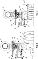
figures 1, 2 and3 are lateral views of the appliance according to the invention, used to handle packs of a source pallet, in different moments of the embodiment of the method according to the invention; -
figure 4 is a lateral view of the appliance according to the invention, in a phase of the method according to the invention wherein it has picked up a pack from the source pallet, comprising bottles of different size than those shown in the previous illustrations; -
figure 5 is a lateral view of the appliance according to the invention that picks up a pack from the source pallet, during a phase of the method according to the invention, complying with a particular gripping mode; -
figure 6 andfigure 7 are lateral views of the appliance which loads on a client pallet a respective pack, of different size, picked up from the source pallet, according to a mode of the method according to the invention which takes into account the presence of walls of products; -
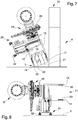
figure 8 shows a phase of the method according to the invention, wherein a suction grip device of the appliance takes a separation element arranged between two layers of the source pallet; -
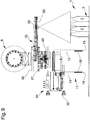
figure 9 shows the use in the method according to the invention of an acquisition device of the images to detect the arrangement of packs in a layer of the source pallet;figure 10 shows a lateral view in vertical section of a lower portion of the appliance according to the invention in one of its particular embodiments; -
figure 11 is a lateral view of the appliance according to the invention, in a further particular embodiment; and -
figures 12 - 15 are schematic views from the top of the source and client pallets showing phases of embodiment of the method according to the invention. - The method of the invention is particularly intended for use in the above-mentioned third-party warehouses, in which single-
product pallets 1 arrive, made up of said shrink-wrappedplastic bottles 2, which hereinafter will be called "source pallet" 1. Notice that in the present description, by the word "pallet" reference is made to the parcel comprising both the pallet and the products supported on it, and not to the pallet alone. - Furthermore, by the word "pack" 3, reference is made to the entire assembly made up of a group of plastic bottles and of the film (normally shrink-wrap) holding the entire assembly together, and not to the film alone.
- The shrink-wrapped
packs 3 are known to have a substantially prismatic shape and a substantially rectangular perimeter. - The invention has been devised to repalletize the shrink-wrapped
plastic bottles 2, i.e., according to the meaning given by the present description, to pick up the shrink-wrappedpacks 3 from thesource pallet 1 and arrange them on one or more multiproduct pallets 4 (hereinafter "client pallet"), in a number established by the order placed by the retailers for whom theclient pallets 4 themselves are intended. Consequently, during repalletizing, as will be seen in detail below, we have, at the same time, de-palletizing and palletizing of the shrink-wrappedpacks 3, i.e., advantageously, for the first time it is possible to perform a direct "pick and place" operation between thesource pallet 1 andclient pallets 4, within the ambit of the shrink-wrappedplastic bottles 2. -
Such bottles 2 are normally made of polyethylene terephthalate (PET) and can be made available in different sizes (an aspect we shall come back to in a subsequent paragraph), and contain water or other drinks. - The
source pallet 1 comprises a plurality of superimposed layers (i.e., stacked), each consisting of a plurality of shrink-wrappedpacks 3, to define a top layer and a bottom layer. - In theory, the method can also work in the event of the
source pallet 1 including only one layer, though this is a case which does not occur in practice. - In any case, the
source pallet 1 is presented to the warehouse (and is therefore made available for the proposed method) comprising a layer accessible from the top, whether this be the top layer or the only layer. - For reasons of illustrative simplicity, in the
figures 1 - 5 and9 , thesource pallet 1 is approximately represented by such accessible layer, which is schematically shown by two or three adjacent packs 3 (see for example thefigure 1 ). - Notice that the phases of the method of the invention illustrated below refer to the
source pallet 1 without (or already deprived of) the shrink-wrap films or other outer wrappings. - Each
pack 3 of each layer, before repalletizing, is adjacent toother packs 3, for space optimization reasons, and is arranged with respect to the other packs in positions and orientations that take into account their size, the number of theirbottles 2 and the size of therespective source pallet 1, on the basis of related standards, as any expert in the field is well aware. - Clearly, the
bottles 2 are arranged in the layer with thebottom 5 below and thecap 6 at top (see in particular thefigures 1 and 2 ), at whichcap 6, thebottles 2 present the respective neck 7, tapered upwards, which is an aspect of interest for the present method. - Typically, the layers of the
source pallet 1 are intercalated by sheet-shaped separation elements 8, usuallycardboard sheets 8, one of which is shown in thefigure 8 , which is a further aspect taken into account by the present method, as will be made clear afterwards. - As has been said, the shrink-wrapped
packs 3 of thesource pallet 1 are preferably distributed toseveral client pallets 4, because various retailers (think of minimarkets)order client pallets 4 with a specific composition of goods, in particular, a specific number ofpacks 3 taken from thecommon source pallet 1. - To do this, handling means are provided comprising an
anthropomorphous robot 9 and agripper 11, carried by saidrobot 9, equipped with two plate-shaped jaws gripper 11 is considered as the "hand" of the handling means 9, 11. - In this case, the
gripper 11 is an interchangeable grip means, i.e., a so-called "end effector". - On the attached tables, the
robot 9 of the invention is approximately shown by its attachment member, but this should be deemed as a mere choice of the representative kind and is not limiting within the scope of the invention. - The
gripper 11 can then be suitable for rotating with respect to the prefixed axes which pass either at theattachment member 9 or cross thegripper 11 itself at any hinge or joint (as in the particular embodiment shown infigure 10 ). - In detail, the gripper can be suitable for being able to rotate around one of its central axes L substantially parallel to the
jaws figure 11 . - In practice, the attachment member can also act as a means to rotate the
gripper 11 with respect to the arm; in addition, or alternatively, thegripper 11 can rotate around one or more of its own axes A. - The
jaws free extremity jaws portions 30 with high friction coefficient, scabrous or in rubber material or both things together (see for examplefigure 1 andfigure 9 ). - Preferably, a
jaw 12 is mobile, and theother jaw 13 is fixed with respect to the rest of thegripper 11. - In a particular embodiment of the
gripper 11, shown infigure 11 , it comprises athinner jaw 13 and athicker jaw 12. - Preferably, the
thinner jaw 13 is the fixed jaw. - The movement of the
mobile jaw 12 can be implemented by means of pneumatic means or, preferably, by means of power actuators or again by means of other movement means known in the sector, and not therefore delved into in the present description. - Because the handling means 9, 11 have to move repeatedly to pick up
packs 3 from thesource pallet 1 and load them onto thevarious client pallets 4 presented to it, it is preferable that the robot of the invention be operative at round angle. - The method of the invention provides for the phase of identifying, in the above layer accessible from above, a shrink-wrapped
pack 3 to be picked up, which hasopposite grip sides jaws - In detail, the shrink-wrapped
pack 3 to be picked up can comprise small bottles (which is the case of thefigures 4 ,7 and9 ), i.e., of a size below one liter, or bottles of above one liter, as in thefigures 1, 2 ,3 ,5 and 6 . - In both cases, the
grip sides pack 3 to be picked up are preferably defined by its longer sides. - The identification of the
pack 3 to be picked up can be preceded by a phase of detection of the position of thepacks 3 in the layer, account of which will be given after explaining in detail the fundamental steps of the method of the invention. - The
gripper 11 is arranged over the shrink-wrappedpack 3 to be picked up, preferably in a divaricated configuration in which thejaws grip sides figure 1 , thegripper 11 is lowered to grip thepack 3, and this is done in a way following the steps explained below. - First of all, shrink-wrapped
packs 3 are always picked up which have at least afree grip side packs 3. - In practice, therefore, the
first pack 3 picked up is always one of the perimeter packs 3 of the layer, i.e., one of itsoutermost packs 3 defining the periphery of the layer. - The
packs 3 subsequently picked up can be both perimeter packs 3 and packs 3 initially arranged inside the layer, agrip side outer packs 3. - In any case, if the shrink-wrapped
pack 3 to be picked up has a firstfree grip side 16 and thesecond grip side 17 adjacent to an extraneous pack (i.e., different from that to be taken), then ajaw 13, during the descent movement of thegripper 11, is forcibly fitted between thesecond side 17 and the extraneous pack (i.e., one of the sides of the latter), withsuch jaw 13 which is parallel to thesecond side 17 itself (seefigure 2 ). This is favored both by the yielding capacity and elasticity of theplastic bottles 2 and of the film that wraps around therespective pack 3, and by the presence of anupper flaring 18, defined by the necks 7 of the bottles which belong to twoadjacent packs 3, and shown in particular in thefigures 1 and 2 . - In fact, considering that each neck 7 tapers towards the
respective cap 6, and is wrapped in adherence by the film, then twoadjacent packs 3 define with one another, in the proximity of the top, a flaring 18 turned upwards with V shape (but which can have different shapes according to the appearance of the neck 7 of the shrink-wrapped bottles 2). - Consequently, the presence of the flaring 18 helps permit a fluid insertion of said
jaw 13 between two different shrink-wrappedpacks 3, without therespective bottles 2 or the respective films being damaged. - The forceful thrust of the
jaw 13 between thepack 3 to be picked up and an adjacent one produces an albeit small divarication between these shrink-wrappedpacks 3, and in practice singularizes thepack 3 to be picked up. - At this point, the
other jaw 12 abuts with the abovefirst side 16, i.e., the free side, to clasp thepack 3 to be picked up in the gripper 11 (figures 3, 4 and5 ). - Even more in detail, in the preferential case in which the
gripper 11 comprises a fixedjaw 13 and amobile jaw 12, the action of the previous paragraph can be performed in two different ways according to two possible situations. - In the most simple situation, shown in the
figure 2 , wherein thejaw 13 forcibly pushed along thesecond grip side 17 is the fixed jaw, then, after insertion, themobile jaw 12, which was initially spaced away, is moved towards the shrink-wrappedpack 3 until it abuts with thefirst grip side 16, to define a grip configuration of the gripper which is like that shown in thefigures 3 and 4 . - Alternatively, if the jaw forcibly pushed between the shrink-wrapped
pack 3 to be taken and an extraneous one is themobile jaw 12, then, for the fixedjaw 13 to approach thefirst side 16, thegripper 11 must be moved by therobot 9 towards the aforementioned extraneous pack, while themobile jaw 12 is moved in the opposite direction, with the same stroke. - This way, in the same way, the firm grip is achieved of the shrink-wrapped
pack 3 by thegripper 11, as can be seen infigure 5 . - In the case, not shown, wherein, in a second or subsequent repalletizing cycle, the
pack 3 identified for pickup, has both grip sides 16, 17 free, then eachjaw gripper 11 has dropped far enough, abuts against a respective side, to clasp on saidpack 3. - In detail, in this case, it is possible but not necessary for a
jaw other jaw - After the
gripper 11 has taken thepack 3, it lifts it and removes it from thesource pallet 1 and takes it to theclient pallet 4, e.g., above it or in close proximity to the perimeter. - At this point, a load position is identified in the
client pallet 4, intended to house the takenpack 3. - To make such identification, specific methods exist, and others can be provided, implemented in computer programs, installed in the computer that controls the handling means 9, 11.
- At this point, the
pack 3 is rested in said load position, according to different procedures. - In a first procedure, the pack is loaded by simply lowering and then opening the
gripper 11, so as to release the shrink-wrappedpack 3. - Alternative procedures will be explained subsequently.
- Unless the order placed by the retailer envisages a
single pack 3 for itsclient pallet 4, the phases described above, starting with the identification of thepack 3 to be picked up from thesource pallet 1 until the release of the shrink-wrappedpack 3 on theclient pallet 4, are repeated cyclically until the above number of shrink-wrappedplastic bottles 2 is reached included in the order placed by the retailer. - The same goes for the case wherein the same
anthropomorphous robot 9 servesvarious client pallets 4 at the same time, which have to contain the goods of the orders of other retailers, which are intended to receive thepacks 3 which have reached the warehouse with thesame source pallet 1 or withseveral source pallets 1. Furthermore, once all the shrink-wrappedplastic bottles 2 of the top layer have been repalletized, then the above indicated repalletizing steps are applied to thepacks 3 of the layer underneath which becomes the new layer accessible from above (after, if necessary, the removal step of the above sheet ofcardboard 8, by means of subsequently introduced means), and so on until the complete repalletizing of all thebottles 2 of thesource pallet 1. - In practice, every time the
bottles 2 of a layer have been repalletized, the layer that was previously arranged immediately below becomes the new top layer, until only what was the bottom layer remains. - From the explanation of the method presented above, it clearly appears that the method of the invention allows third-party warehouses to completely do without the secondary warehouses spoken of when describing the prior art.
- In fact, because, using the proposed method, an intermediate palletizing of one layer of
packs 3 is not necessary, it is the source pallet itself 1 which continues to accommodate the shrink-wrappedbottles 2 in the primary warehouse until these are repalletized in aclient pallet 1. - Furthermore, the method has been provided so as to be able to have successful repalletizing achieved entirely automatically, no manual intervention at all being required from the warehouse personnel.
- In the event of a
wall 19 of products being present alongside the load position, defined by a number of stacked products, then loading is done according to a procedure described below. - The mentioned
wall 19 of products, as shown in thefigures 6 and7 , extends vertically and protrudes at the top with respect to the supportingbase 22 of thepack 3. - By supporting
base 22 is meant the horizontal surface, placed at the load position, which has to sustain the shrink-wrappedpack 3 once loaded on theclient pallet 4, and which is defined either by its pallet or by the top of a layer of already-loaded goods. Thewall 19 of products represents an obstacle that could hinder the collocation of thepack 3 on theclient pallet 4. - In fact, considering the
gripper 11 occupies a given space and has an irregular shape, the risk exists that, during the phase of resting thepack 3 in the respective load position, which is adjacent to thewall 19, a collision occurs between gripper andwall 19, with the consequent falling onto the ground of the goods stacked in the latter. - This accident would imply having to revert to the use of manual intervention to collect and reposition the goods themselves, or even to a very costly suspension of repalletizing.
- To overcome these possible drawbacks, the proposed method envisages various solutions for loading the
pack 3 in the case of the presence ofwalls 19 of products. - A first solution is explained below with the aid of the
figures 6 and7 , which show the implemented phases of the method with regard to packs with large-size bottles and packs with small-size bottles respectively. - First of all, the
gripper 11 is moved over the load position, in an inclined arrangement wherein the fixedjaw 13 is facing thewall 19. - In detail, to such arrangement of the
gripper 11 corresponds a relative inclined arrangement of thepack 3, wherein this has agrip side 17 closer to thewall 19 and anopposite side 16 farther away, lying on planes that are oblique with respect to thewall 19, and wherein the shrink-wrappedpack 3 touches theclient pallet 4 only along one of itscorners 20 defined at the lower edge of its furthest awayside 16, so that such corner is substantially parallel to thewall 19, i.e., to the vertical plane on which extends thewall 19 or on which lies itsface 23 placed adjacent to the load position. - In geometric terms, it can be said that, when the
pack 3 is in said inclined arrangement, itsclosest side 17 lies on a plane oblique to the plane of extension of thewall 19, which is vertical, to define with this substantially a band of own planes, i.e., a band of planes that originates from a straight line. - In any case, initially, the
pack 3 only touches the load position with said lower corner, at a distance from the wall which is at least the distance between its twogrip sides - At this point, the
pack 3 rotates towards thewall 19, until it is positioned with the grip sides 16, 17 parallel to thewall 19, and clearly with its base bottom 21 linking belowsuch sides base 22. - To achieve this, preferably, the
mobile jaw 12, abutted with thegrip side 16 furthest away, is operated in away movement fromsuch side 16. - At this moment, the
pack 3 rests inclined because also resting against the fixedjaw 13; for this purpose, the inclination of thepack 3 is chosen in such a way that, once the mobile jaw has left it, it does not fall in the opposite direction to the wall onto itsfurthest grip side 16. - After which, the
gripper 11 is raised detaching the fixedjaw 13 from theclosest side 17 to thewall 19, to enable thepack 3 to rotate by gravity towards thewall 19 until it rests in support, with its base bottom 21, in said load position. - The second loading solution is preferably implemented by means of the
gripper 11 in its version complete with thinner fixedjaw 13 as shown infigure 11 . - The second solution envisages the
gripper 11, bearing thepack 3 to be loaded, being first of all arranged above the load position. - In detail, the
gripper 11 is oriented so the fixedjaw 13 is arranged on a substantially vertical plane adjacent to the above-mentionedface 23 of thewall 19. - In practice, the surface F on which lies the fixed
jaw 13, which hereinafter is called front surface F, is arranged vertically and substantially at the plane on which is placed theface 23 of the wall adjacent to the load position. - The front surface F therefore passes along the perimeter of the load position.
- At this point, the
gripper 11 is lowered by translating it vertically until it places thepack 3 in the load position (seefigure 11 ). - Because the
jaw 13, which skims or is in any case facing thewall 19 of products, is thin, thepack 3 can be loaded in a position wherein it is as close as possible to thewall 19, so as to obtain highly efficient use of the space available on theclient pallet 4. - Preferably, the
gripper 11 of the invention is included in anappliance figure 11 ). In practice, theappliance - Consequently, when the
gripper 11 drops to load thepack 3, thewall 19 does not suffer knocks. - After the loading phase, the
mobile jaw 12 moves away from thepack 3, leaving it in its load position. - Finally, the
gripper 11 is raised vertically leaving thepack 3 on theclient pallet 4. - For the same reasons discussed above, in this case too, the
wall 19 suffers no knocks. Preferably, theopposite extremity 51 of the above-mentionedfree extremity 15 of the fixedjaw 13, comprises a rounded shape to prevent it, during lifting, from knocking against a product badly arranged inside thewall 19 and causing the latter to fall. - The method of the invention then provides for further preferential solutions for the case wherein the load position is at an internal angle, e.g., right-angle, formed by a first and by a second wall of
products figures 13 and 15 ). - In this case, the problem can arise whereby, though avoiding any knocking against the
first wall 19 during the loading phase, thanks to the implementation of the above-mentioned phases, the gripper knocks against thesecond wall 36 with the extremity edges of the jaws. - To prevent this, during pickup from the
source pallet 1, thegripper 11 takes thepack 3 so that at least an extremity of the gripper itself, defined by the extremity edges of thejaws opposite sides 39 of thepack 3, which are orthogonal to the above-mentioned grip sides 16, 17, which hereinafter will be called firstorthogonal side 39. - In practice, the
gripper 11 has been designed to takepacks 3 of different size; it can thus occur that thepacks 3 of a givensource pallet 1 have shorter grip sides 16, 17 than thegripper 11, i.e., shorter than itsjaws - This situation can occur when the
gripper 11 picks up e.g. apack 3 made up of six half-litre bottles. - In this case, if the
pack 3 were taken so that both extremities of thegripper 11 protrude from itsorthogonal sides 39 to the grip sides 16, 17, then it would be unable to convey thepack 3 to a load position situated in said internal angle of thewalls jaws second wall 36. - Therefore, having picked up the
pack 3 in the way explained above, thegripper 11 then places it in the load position positioned with its firstorthogonal side 39 facing and adjacent to thesecond wall 36. - This way, the thin fixed
jaw 13 and the first orthogonal side of thepack 3 find themselves positioned on the perimeter sides of the load position and facing the first and thesecond walls - After this, the
mobile jaw 12 is moved away and thegripper 11 is moved away from theclient pallet 4 as explained above, obviously leaving thepack 3 loaded. - As has been said, the
gripper 11 can rotate around the above vertical central axis L, so as to correctly direct it according to the arrangement of thewalls client pallet 4. - The
thinner jaw 13 must however always be adjacent to one of the twowalls client pallet 4, andsuch jaw 13 is also parallel to the loadedpack 3. - Consequently, depending which wall has to be parallel to the
pack 3 following loading, here called "first wall" 19, the grip mode of thepack 3 during pickup from thesource pallet 1 will vary. - In practice, such grip is made according to the following rules.
- If, as shown in
figure 13 , thefirst wall 19 and thesecond wall 36 are to the left and right respectively of the internal angle (i.e., the concave angle) then, during pickup, thethinner jaw 13 is forcibly fitted between the abovesecond grip side 17 of the pack to be picked up and the abovedifferent pack 3, i.e., the previously mentioned adjacent pack (seefigure 12 ). - If, on the other hand, as shown in
figure 15 , thefirst wall 19 and thesecond wall 36 are the right side and the left side respectively of the angle, then thethicker jaw 12 will be the one forcibly fitted between thesecond grip side 17 of the pack to be picked up and thedifferent pack 3 defined above (seefigure 14 ). - As said above, when the layers of the
source pallet 1 are intercalated byseparation elements 8 like the aforementioned sheets of cardboard, which nearly always occurs every time all the shrink-wrappedplastic bottles 2 initially loaded on one ofsuch separation elements 8 have been repalletized, theseparation element 8 is removed and placed in a collection seat. - This way, the layer of
underlying bottles 2 is made accessible from above. - To do this, a
suction grip device 24 can be provided, connected to a vacuum source, carried by therobot 9 and associated with thegripper 11, which device is used in the following way. - The
suction grip device 24 is moved at theseparation element 8 to be removed, i.e., at its upper surface, which is accessible, and is then operated so as to fasten onto theseparation element 8 itself by suction (as shown infigure 8 ). - After this, the
suction grip device 24 is lifted so as to drag with it saidseparation element 8 and bring it at the collection seat, where it is left, following the deactivation of thedevice 24 itself. - This
suction grip device 24 can e.g. be fitted on thegripper 11, either fixed or mobile with respect to this; in the second case it can be moving in translation (as in the case offigures 1 - 9 ) or in rotation (as infigure 10 , as will be detailed when describing theappliance - To determine the identification phase of the
pack 3 to be picked up, it may be very important to determine beforehand the arrangement of all the packs in the layer accessible from above. - This way, the above processing unit is able to know both the exact position of each
pack 3 of the layer, and their position, and can therefore suitably command the handling means 9, 11, so they are arranged from time to time in the best configuration for picking up the identifiedpack 3. - For such purpose, an
image acquisition device 25 can be provided, e.g., having acamera 29 or other similar means, carried by saidrobot 9, associated with saidgripper 11 and connected to the processing unit. - In practice, the
acquisition device 25 is arranged above the layer, before or during the several times mentioned identification phase, so as to determine the arrangement of the packs 3 (seefigure 9 ), communicating this to the processing unit which will use such information in the subsequent phases when commanding the handling means 9, 11 for gripping. - Preferably, for encumbrance reasons, with special reference to the critical aspect of the presence of
walls 19 of products on theclient pallets 4, theacquisition device 25 is fitted sliding with respect to thegripper 11, so as to be able to move between a position of use, shown infigure 9 , wherein it protrudes overhanging in a semi-plane defined by the fixedjaw 13, which does not include theother jaw 12, and a retracted position, shown infigures 1 - 8 and11 , wherein it is mostly arranged in the other semi-plane. - In practice, the
acquisition device 25 can be, e.g., fitted in a fixedframe 26 with respect to the above-mentionedattachment member 9, and be, at the bottom, equipped with a connection means 27 fixable in a releasable way to a corresponding connection means 28 fixed above the gripper 11 (and in fact, infigure 10 , thegripper 11 and thesuction grip device 24 are shown separated from the acquisition device 25). - In detail, the aforementioned connection means 27, 28 together define an automatic tool-changing device for robots, in itself known.
- Different configurations are nevertheless possible as regards the connection between
robot 9,gripper 11,suction grip device 24 andacquisition device 25. - According to an optional aspect of the invention, a
touch probe device 31 is made available associated with thegripper 11 and connected to theprocessing unit 3. - In particular, the
touch probe device 31 can be fitted on thesuction grip device 24, e.g., in a median position with respect to itssuction cups 32. - Such touch probe device (hereinafter simply "feeler" 31) can be used in cooperation with the
acquisition device 25 to detect the arrangement of thepacks 3 of the accessible layer, so as to implement the identification phase, according to the procedure explained below. - The
feeler 31 of the invention comprises a particular type of "stylus" having a substantially plate shape, for reasons that will be explained in the following paragraphs, and which will here be called "abutment element" 33. - In practice, the
feeler 31 is a measuring instrument which provides the amount of movement completed by theabutment element 33 before abutting with an obstacle.Such abutment element 33 is meant to touch thepacks 3 with its edge 34 (or side) which is not sharp and is of limited thickness, in detail less than the distance between two caps of thebottles 2 of apack 3. - The
abutment element 33 is nevertheless thick enough not to tear the film wrapped around thebottles 2 of apack 3, when it abuts it. - The
abutment element 33, being plate shaped, substantially defines a lying plane, along which it is mobile in translation for the purposes of taking the measurements for which it was designed. - After the
acquisition device 25 has provided the image of the view from above of the layer, the processing unit has at least at disposal the arrangement of thebottles 2 inside the layer (substantially a piece of information corresponding to their Cartesian coordinates) but it can occur that the information relating to the border line betweenpacks 3 is imprecise or cannot be detected due to the limits of current optical technology or of the identification software. - The use of the
feeler 31 overcomes such limits by exploiting three data. - The first datum consists of the size of the
packs 3 of thesource pallet 1, i.e., the number ofbottles 2 making up the longer side and those that form the shorter side of thepacks 3 present in each layer. - The second datum is the fact that, while the
bottles 2 of a givenpack 3 are connected at the top by the respective film, betweenbottles 2 ofadjacent packs 3 is defined, in the proximity of the top, theforementioned flaring 18. - Consequently, by positioning the
feeler 31 above aperimeter pack 3 at a distance from the edge of the layer (i.e., one of the sides of the pallet 1) corresponding to the number ofbottles 2 of the shorter side of thepacks 3 and then operating thefeeler 31 itself, the information is obtained of the direction of thispack 3. - In fact, if the
feeler 31 measures a short movement of itsabutment element 33, this means that theedge 34 of the latter has encountered the film of thepack 3, while if it measures a long movement, this means it has reached the bottom of theflaring 18. - In the first case, the length of the
pack 3 is perpendicular to theabutment element 33, while in the second case it is parallel to this and these two cases correspond to the only two possible orientations of thepack 3. - The third datum is the fact that the size of the
packs 3 and of thepallet 1 univocally determine the arrangement of thepacks 3 in the layers; consequently the knowledge of the orientation of one of thepacks 3 automatically implies the knowledge of the orientation of all theother packs 3 of the same layer. - Consequently, by using the
feeler 31 in the way explained above, it is possible, with a single measurement operation, to determine the arrangement of all thepacks 3 of a layer and, if all the layers of thepallet 1 are the same, of all thepacks 3 of thepallet 1. In the event of its not being known whether the different layers are the same, as regards the arrangement of thepacks 3, then it will be enough to take a single measurement per layer, to be able to successfully implement the proposed method. Thefeeler 31 can also be used to detect the exact distance off the ground of the layer from time to time accessible from above and of the above-mentionedseparation elements 8. - In fact, in order to correctly pick up the
packs 3 and remove saidseparation elements 8, besides the general information regarding their height, already known but in a rather rough way, it could be useful to also have a fine measurement. - By placing the
feeler 31 at a predetermined height, and then measuring the amount of movement of theabutment element 33 to touch the top of the layer or of theseparation elements 8, their exact height is automatically obtained. - The
appliance - The proposed
appliance plastic bottles 2, i.e., it has been designed to implement the method explained above. - The
appliance distal extremity 9 of the articulated arm. - The proposed
appliance gripper 11, configured as already explained in detail above, during the description of the method of the invention. - Furthermore, the
appliance acquisition device 25 and thetouch probe device 31. - The characteristics concerning the
gripper 11, theacquisition device 25 and thefeeler 31, introduced and discussed above in relation to the method, just like their preferential or optional versions indicated above, apply in the same identical way to theappliance - The operation of the
appliance - In particular, it should be noticed that the
acquisition device 25 is fitted retracting on the above-mentionedsupport frame 26, as explained above in greater detail, and can include, besides theabove camera 29, also lighting means 50, e.g., made up of a luminous panel. - Preferably, the
appliance suction grip device 24, whose structure and operation have been described previously. - The particular embodiment in the
figure 10 envisages a version of thesuction grip device 24, wherein it comprises asupport arm 35, e.g., with a V or elbow shape, which bears the above-mentionedsuction cups 32 and is suitable for rotating with respect to thegripper 11 between a work position and an inactive position. - In this case, the
arm 35 can also bear thetouch probe device 31. - In the particular embodiment shown in
figure 11 , as already mentioned above, all the components of theappliance thinner jaw 13, are arranged in just one of the two semi-planes defined by the front surface F on whichsuch jaw 13 lies. - It has in fact been ascertained how the described invention achieves the proposed objects and in particular the fact is underlined that it makes available a method and an
appliance
Claims (15)
- Method for repalletizing shrink-wrapped packs of plastic bottles (2), characterised by the following steps:a. providing at least a source pallet (1) comprising at least one layer, made up of a plurality of shrink-wrapped packs (3) of bottles (2) and accessible from the top;b. providing at least a client pallet (4), on which a number of packs (3) of bottles (2) has to be loaded, taken from said source pallet (1);c. providing handling means comprising an anthropomorphous robot (9) and a gripper (11), carried by said robot (9) and equipped with two plate-shaped jaws (12, 13);d. identifying in said layer a pack (3) to pick up, which has opposite grip sides (16, 17);e. arranging said gripper (11) above said pack (3);f. lowering said gripper (11) and gripping said pack (3) with said gripper (11), according to the following rule: if said pack (3) to pick up has a first free grip side (16) and a second grip side (17) adjacent to a different pack (3), then a jaw (13), during the descent movement of the gripper (11), is forcibly fitted between said second side (17) and said different pack (3), wherein the forceful thrust of the jaw (13) between the pack (3) to be picked up and an adjacent one produces a small divarication between these packs (3) and singularizes the pack (3) to be picked up, and the other jaw (12) abuts against said first side (16), so as to clasp the pack (3) to pick up in the gripper (11); if said pack (3) to pick up has both grip sides (16, 17) free, then each jaw (12, 13) abuts a respective grip side (16, 17), so as to clasp the pack (3) in the gripper (11);g. lifting said pack (3) and carrying it by said client pallet (4);h. identifying a load position in said client pallet (4) where arranging said pack (3);i. placing said pack (3) in said load position; andj. if said number of packs (3) is more than one, repeating the steps from d. to i. until reaching said number.
- Method according to claim 1, characterized in that, when the source pallet (1) comprises a plurality of superimposed layers, the steps from d. to i. are systematically repeated and applied to the packs of plastic bottles (2) of each layer, repalletizing all the packs (3) of a layer accessible from the top before moving on to the layer immediately below, starting from the top layer up to the bottom layer.
- Method according to one or more of the preceding claims, characterized in that, when said load position is arranged alongside a group of products piled on said client pallet (4), so as to define a wall (19) of products, the step i. comprises the following actions:k. said pack (3) is arranged in an inclined configuration, in which it has a grip side (17) closer to said wall (19), and a grip side (16) farther to it, both lying on an oblique plane with respect to said wall (19), and in which said pack (3) touches said client pallet (4) only along one of its corners (20) at the bottom of said farther grip side (16), so that said corner (20) is substantially parallel to said wall (19); then1. said pack (3) rotates towards said wall, until arranging itself with said grip sides (16, 17) parallel to said wall (19), so as to rest free in said load position.
- Method according to claim 3, characterized in that said action 1. of the step i. is carried out as follows: said jaw (13) against said farther grip side (16) of the pack (3) moves away from said grip side (16), then the gripper (11) is lifted, releasing the other jaw (13) from said closer side (17), so as to allow said pack (3) to rotate by gravity towards said wall (19) until stopping itself resting in said load position.
- Method according to one or more of the preceding claims, characterized in that a gripper (11) is used which has a thicker jaw (12) and a thinner jaw (13).
- Method according to one or more of the preceding claims, characterized in that, when said load position is arranged alongside a group of products piled on said client pallet (4), so as to define a first wall of products (19), the phase i. comprises the following actions:m. arranging said gripper (11) above the load position, directed so that a first jaw (13) of said gripper (11) is arranged in a substantially vertical plane adjacent to that of a face (23) of said first wall (19);n. lowering in vertical said gripper (11) to place said pack (3) in said load position;o. moving away a second jaw (12) opposite the first one from said pack (3), releasing it; andp. lifting vertically said gripper (11) leaving the pack (3) on said client pallet (4).
- Method according to claims 5 and 6, characterized in that said first jaw (13) is the thin jaw and said second jaw (14) is the thick jaw.
- Method according to one or more of the preceding claims, characterized in that, in step f., the gripper grips said pack (3) so that at least one of its extremities (37, 38) does not protrude from at least a first side (39) of said pack (3) orthogonal to said grip sides (16, 17).
- Method according to claim 8, characterized in that, in case said packs (3) to pick up have shorter grip sides than said gripper (11), if said load position is at an inner corner made up of said first wall (19) of products and a second wall (36) of products, defined by respective groups of products piled on said client pallet (4), then, in step i., said pack (3) rests and is left in the load position directed with said first orthogonal side (39) facing said second wall (36).
- Method according to claims 7, 8 and 9, characterized in that:- if said first wall (19) and said second wall (36) are the left and right side respectively of said corner then, during the step f., said thinner jaw (13) is forcibly fitted between said second grip side (17) of the pack to pick up and said different pack (3); and- if said first wall and said second wall (19, 36) are the right and left side respectively of said corner then, during the step f., said thicker jaw (13) is forcibly fitted between said second grip side (17) of the pack to pick up and said different pack (3).
- Method according to one or more of claims from 2 to 10, characterized in that, when said layers are separated by sheet-shaped separation elements (8), each time all the packed plastic bottles (2) loaded on one of said separation elements (8) have been repalletized, the latter is removed from said source pallet (1) and placed in a collection seat.
- Method according to claim 11, characterized by providing a suction grip device (24), carried by said robot (9) and associated with said gripper (11), used to remove said separation element (8) as follows: said suction grip device (24) is brought at said separation element (8), then it is activated so as to fasten said separation element (8), then it is lifted so as to drag said separation element (8) with it and carry it at said seat, where it is left, following the de-activation of said suction grip device (24).
- Method according to one or more of the preceding claims, characterized by providing an image acquisition device (25) carried by said robot (9), associated with said gripper (11) and connected to a processing unit which controls said robot (9) and said gripper (11), said acquisition device (25) being arranged above said layer, before step e., so as to detect the arrangement of said packs (3) in said layer, said arrangement being used by said unit to carry out step d.
- Method according to one or more of the preceding claims, characterized by providing a touch probe device (31) associated with said gripper (11) and connected to a processing unit (3) which controls said robot (9), said touch probe device (31) being arranged above said layer, before step e., and used to detect the arrangement of said packs (3) in said layer, which arrangement is used by said unit (3) to carry out step d.
- Method according to claim 14, characterized in that said touch probe device (31) is used to detect the distance from the ground of said layer and of said separation elements (8).
Applications Claiming Priority (3)
| Application Number | Priority Date | Filing Date | Title |
|---|---|---|---|
| IT000124A ITMO20130124A1 (en) | 2013-05-10 | 2013-05-10 | METHOD AND EQUIPMENT FOR THE REPALLETIZATION OF PLASTIC BOTTLES |
| IT000246A ITMO20130246A1 (en) | 2013-09-06 | 2013-09-06 | METHOD AND EQUIPMENT FOR THE REPALLETIZATION OF PLASTIC BOTTLES |
| PCT/IB2014/061297 WO2014181285A1 (en) | 2013-05-10 | 2014-05-08 | Method and appliance for repalletizing shrink-wrapped packs of plastic bottles |
Publications (2)
| Publication Number | Publication Date |
|---|---|
| EP2994403A1 EP2994403A1 (en) | 2016-03-16 |
| EP2994403B1 true EP2994403B1 (en) | 2017-07-26 |
Family
ID=50884967
Family Applications (1)
| Application Number | Title | Priority Date | Filing Date |
|---|---|---|---|
| EP14728334.5A Not-in-force EP2994403B1 (en) | 2013-05-10 | 2014-05-08 | Method and appliance for repalletizing shrink-wrapped packs of plastic bottles |
Country Status (2)
| Country | Link |
|---|---|
| EP (1) | EP2994403B1 (en) |
| WO (1) | WO2014181285A1 (en) |
Families Citing this family (7)
| Publication number | Priority date | Publication date | Assignee | Title |
|---|---|---|---|---|
| CN106542329A (en) * | 2015-09-18 | 2017-03-29 | 今日机械设备(大连)有限公司 | Fan iron core, gesture recognition, loading and unloading balance, Multi-position processing machine device people and its method of work |
| DE202015009700U1 (en) * | 2015-09-21 | 2019-04-05 | Alexander Schier | Device for repacking packaged unit packaged goods |
| FR3041947B1 (en) * | 2015-10-06 | 2020-02-07 | Sapelem | LOAD HANDLING METHOD AND DEVICE, CALLED PACKAGE |
| CN106185304B (en) * | 2016-08-25 | 2018-07-31 | 中国大冢制药有限公司 | Filling production lines medicine bottle clamp device |
| CN108750690B (en) * | 2018-07-23 | 2024-01-19 | 合肥泰禾光电科技股份有限公司 | Suction device, unstacking device and unstacking method |
| CN110723530B (en) * | 2019-09-27 | 2024-04-26 | 天津新玛特科技发展有限公司 | Automobile body-in-white assembly robot grasping equipment |
| CN110759115A (en) * | 2019-11-21 | 2020-02-07 | 湖南雪峰食品发展有限公司 | Fruit can stacking machine |
Family Cites Families (7)
| Publication number | Priority date | Publication date | Assignee | Title |
|---|---|---|---|---|
| JPS59149234A (en) * | 1983-02-08 | 1984-08-27 | Daifuku Co Ltd | Method of separating box-like objects |
| DE3440954C2 (en) * | 1984-11-09 | 1992-03-12 | Möllers Maschinenfabrik GmbH, 4720 Beckum | Device for gripping and setting down piece goods |
| GB8602105D0 (en) * | 1986-01-29 | 1986-03-05 | Precision Eng Products Suffolk | Automatic article handling methods |
| ITMO20020050A1 (en) * | 2002-02-28 | 2003-08-28 | Ferrari & Cigarini Srl | DEVICE FOR THE DEPALLETIZATION OF TILE PACKAGES |
| US20070280812A1 (en) * | 2006-05-17 | 2007-12-06 | Axium Inc. | Tool and method for mixed palletizing/depalletizing |
| US7547052B2 (en) * | 2006-05-25 | 2009-06-16 | Dyco, Inc. | Robotic head for palletizing full boxes, tray packs and spot packs |
| DE102008035330A1 (en) * | 2008-07-29 | 2010-02-04 | Krones Ag | Device for picking and / or relocating several palletized containers |
-
2014
- 2014-05-08 WO PCT/IB2014/061297 patent/WO2014181285A1/en not_active Ceased
- 2014-05-08 EP EP14728334.5A patent/EP2994403B1/en not_active Not-in-force
Non-Patent Citations (1)
| Title |
|---|
| None * |
Also Published As
| Publication number | Publication date |
|---|---|
| WO2014181285A1 (en) | 2014-11-13 |
| EP2994403A1 (en) | 2016-03-16 |
Similar Documents
| Publication | Publication Date | Title |
|---|---|---|
| EP2994403B1 (en) | Method and appliance for repalletizing shrink-wrapped packs of plastic bottles | |
| US12344488B2 (en) | Vision-assisted robotized depalletizer | |
| CA3114789C (en) | Vision-assisted robotized depalletizer | |
| US10902377B2 (en) | Robotic item handling using a variable area manipulator | |
| US8295980B2 (en) | Deployment apparatus and method | |
| CN107810155B (en) | Apparatus and method for loading a storage area | |
| US20200376668A1 (en) | Robotic Pack Station | |
| WO2015132720A1 (en) | Gripper with movable jaw and suction device | |
| CN111315545A (en) | Identification code for cargo, display object thereof, and robot hand used for same | |
| CN110421542B (en) | Intelligent robot for loading and unloading box packages | |
| JP2023520348A (en) | System and method for moving and dismantling carton stacks | |
| JP7264387B2 (en) | Robotic gripper assembly for openable objects and method for picking objects | |
| CN103552849A (en) | Robot gripper for box body stacking and unstacking | |
| EP0666149B1 (en) | Robotic egg carton pickup head | |
| WO2015112018A1 (en) | Gripper unit for gripping, picking up, transporting, and discharging boxes | |
| CA3094760C (en) | Affordance for use on an item in a container | |
| KR20220133025A (en) | Unwrapping Apparatus | |
| EP4178890B1 (en) | Handling method and machine to re-arrange ceramic articles of a group of ceramic articles | |
| CN109399196A (en) | Fully automatic feeding device | |
| CN112573053B (en) | Storing and taking mechanism suitable for AGV (automated guided vehicle), AGV and storing and taking method | |
| WO2014108660A1 (en) | Carrier puck | |
| US20120191240A1 (en) | Methods and apparatus for removing an item from a conveyor system | |
| ITMO20130124A1 (en) | METHOD AND EQUIPMENT FOR THE REPALLETIZATION OF PLASTIC BOTTLES | |
| EP2943422B1 (en) | Carrier puck | |
| US20170362042A1 (en) | Supplying of cutouts |
Legal Events
| Date | Code | Title | Description |
|---|---|---|---|
| PUAI | Public reference made under article 153(3) epc to a published international application that has entered the european phase |
Free format text: ORIGINAL CODE: 0009012 |
|
| 17P | Request for examination filed |
Effective date: 20151203 |
|
| AK | Designated contracting states |
Kind code of ref document: A1 Designated state(s): AL AT BE BG CH CY CZ DE DK EE ES FI FR GB GR HR HU IE IS IT LI LT LU LV MC MK MT NL NO PL PT RO RS SE SI SK SM TR |
|
| AX | Request for extension of the european patent |
Extension state: BA ME |
|
| DAX | Request for extension of the european patent (deleted) | ||
| GRAP | Despatch of communication of intention to grant a patent |
Free format text: ORIGINAL CODE: EPIDOSNIGR1 |
|
| STAA | Information on the status of an ep patent application or granted ep patent |
Free format text: STATUS: GRANT OF PATENT IS INTENDED |
|
| INTG | Intention to grant announced |
Effective date: 20170213 |
|
| GRAS | Grant fee paid |
Free format text: ORIGINAL CODE: EPIDOSNIGR3 |
|
| GRAA | (expected) grant |
Free format text: ORIGINAL CODE: 0009210 |
|
| STAA | Information on the status of an ep patent application or granted ep patent |
Free format text: STATUS: THE PATENT HAS BEEN GRANTED |
|
| AK | Designated contracting states |
Kind code of ref document: B1 Designated state(s): AL AT BE BG CH CY CZ DE DK EE ES FI FR GB GR HR HU IE IS IT LI LT LU LV MC MK MT NL NO PL PT RO RS SE SI SK SM TR |
|
| REG | Reference to a national code |
Ref country code: GB Ref legal event code: FG4D |
|
| REG | Reference to a national code |
Ref country code: CH Ref legal event code: EP |
|
| REG | Reference to a national code |
Ref country code: AT Ref legal event code: REF Ref document number: 912162 Country of ref document: AT Kind code of ref document: T Effective date: 20170815 |
|
| REG | Reference to a national code |
Ref country code: IE Ref legal event code: FG4D |
|
| REG | Reference to a national code |
Ref country code: DE Ref legal event code: R096 Ref document number: 602014012282 Country of ref document: DE |
|
| REG | Reference to a national code |
Ref country code: NL Ref legal event code: MP Effective date: 20170726 |
|
| REG | Reference to a national code |
Ref country code: LT Ref legal event code: MG4D |
|
| REG | Reference to a national code |
Ref country code: AT Ref legal event code: MK05 Ref document number: 912162 Country of ref document: AT Kind code of ref document: T Effective date: 20170726 |
|
| PG25 | Lapsed in a contracting state [announced via postgrant information from national office to epo] |
Ref country code: HR Free format text: LAPSE BECAUSE OF FAILURE TO SUBMIT A TRANSLATION OF THE DESCRIPTION OR TO PAY THE FEE WITHIN THE PRESCRIBED TIME-LIMIT Effective date: 20170726 Ref country code: SE Free format text: LAPSE BECAUSE OF FAILURE TO SUBMIT A TRANSLATION OF THE DESCRIPTION OR TO PAY THE FEE WITHIN THE PRESCRIBED TIME-LIMIT Effective date: 20170726 Ref country code: LT Free format text: LAPSE BECAUSE OF FAILURE TO SUBMIT A TRANSLATION OF THE DESCRIPTION OR TO PAY THE FEE WITHIN THE PRESCRIBED TIME-LIMIT Effective date: 20170726 Ref country code: AT Free format text: LAPSE BECAUSE OF FAILURE TO SUBMIT A TRANSLATION OF THE DESCRIPTION OR TO PAY THE FEE WITHIN THE PRESCRIBED TIME-LIMIT Effective date: 20170726 Ref country code: NO Free format text: LAPSE BECAUSE OF FAILURE TO SUBMIT A TRANSLATION OF THE DESCRIPTION OR TO PAY THE FEE WITHIN THE PRESCRIBED TIME-LIMIT Effective date: 20171026 Ref country code: FI Free format text: LAPSE BECAUSE OF FAILURE TO SUBMIT A TRANSLATION OF THE DESCRIPTION OR TO PAY THE FEE WITHIN THE PRESCRIBED TIME-LIMIT Effective date: 20170726 Ref country code: NL Free format text: LAPSE BECAUSE OF FAILURE TO SUBMIT A TRANSLATION OF THE DESCRIPTION OR TO PAY THE FEE WITHIN THE PRESCRIBED TIME-LIMIT Effective date: 20170726 |
|
| PG25 | Lapsed in a contracting state [announced via postgrant information from national office to epo] |
Ref country code: GR Free format text: LAPSE BECAUSE OF FAILURE TO SUBMIT A TRANSLATION OF THE DESCRIPTION OR TO PAY THE FEE WITHIN THE PRESCRIBED TIME-LIMIT Effective date: 20171027 Ref country code: ES Free format text: LAPSE BECAUSE OF FAILURE TO SUBMIT A TRANSLATION OF THE DESCRIPTION OR TO PAY THE FEE WITHIN THE PRESCRIBED TIME-LIMIT Effective date: 20170726 Ref country code: RS Free format text: LAPSE BECAUSE OF FAILURE TO SUBMIT A TRANSLATION OF THE DESCRIPTION OR TO PAY THE FEE WITHIN THE PRESCRIBED TIME-LIMIT Effective date: 20170726 Ref country code: BG Free format text: LAPSE BECAUSE OF FAILURE TO SUBMIT A TRANSLATION OF THE DESCRIPTION OR TO PAY THE FEE WITHIN THE PRESCRIBED TIME-LIMIT Effective date: 20171026 Ref country code: LV Free format text: LAPSE BECAUSE OF FAILURE TO SUBMIT A TRANSLATION OF THE DESCRIPTION OR TO PAY THE FEE WITHIN THE PRESCRIBED TIME-LIMIT Effective date: 20170726 Ref country code: PL Free format text: LAPSE BECAUSE OF FAILURE TO SUBMIT A TRANSLATION OF THE DESCRIPTION OR TO PAY THE FEE WITHIN THE PRESCRIBED TIME-LIMIT Effective date: 20170726 Ref country code: IS Free format text: LAPSE BECAUSE OF FAILURE TO SUBMIT A TRANSLATION OF THE DESCRIPTION OR TO PAY THE FEE WITHIN THE PRESCRIBED TIME-LIMIT Effective date: 20171126 |
|
| PG25 | Lapsed in a contracting state [announced via postgrant information from national office to epo] |
Ref country code: DK Free format text: LAPSE BECAUSE OF FAILURE TO SUBMIT A TRANSLATION OF THE DESCRIPTION OR TO PAY THE FEE WITHIN THE PRESCRIBED TIME-LIMIT Effective date: 20170726 Ref country code: RO Free format text: LAPSE BECAUSE OF FAILURE TO SUBMIT A TRANSLATION OF THE DESCRIPTION OR TO PAY THE FEE WITHIN THE PRESCRIBED TIME-LIMIT Effective date: 20170726 Ref country code: CZ Free format text: LAPSE BECAUSE OF FAILURE TO SUBMIT A TRANSLATION OF THE DESCRIPTION OR TO PAY THE FEE WITHIN THE PRESCRIBED TIME-LIMIT Effective date: 20170726 |
|
| REG | Reference to a national code |
Ref country code: DE Ref legal event code: R097 Ref document number: 602014012282 Country of ref document: DE |
|
| PG25 | Lapsed in a contracting state [announced via postgrant information from national office to epo] |
Ref country code: EE Free format text: LAPSE BECAUSE OF FAILURE TO SUBMIT A TRANSLATION OF THE DESCRIPTION OR TO PAY THE FEE WITHIN THE PRESCRIBED TIME-LIMIT Effective date: 20170726 Ref country code: SK Free format text: LAPSE BECAUSE OF FAILURE TO SUBMIT A TRANSLATION OF THE DESCRIPTION OR TO PAY THE FEE WITHIN THE PRESCRIBED TIME-LIMIT Effective date: 20170726 Ref country code: SM Free format text: LAPSE BECAUSE OF FAILURE TO SUBMIT A TRANSLATION OF THE DESCRIPTION OR TO PAY THE FEE WITHIN THE PRESCRIBED TIME-LIMIT Effective date: 20170726 |
|
| PLBE | No opposition filed within time limit |
Free format text: ORIGINAL CODE: 0009261 |
|
| STAA | Information on the status of an ep patent application or granted ep patent |
Free format text: STATUS: NO OPPOSITION FILED WITHIN TIME LIMIT |
|
| 26N | No opposition filed |
Effective date: 20180430 |
|
| PG25 | Lapsed in a contracting state [announced via postgrant information from national office to epo] |
Ref country code: SI Free format text: LAPSE BECAUSE OF FAILURE TO SUBMIT A TRANSLATION OF THE DESCRIPTION OR TO PAY THE FEE WITHIN THE PRESCRIBED TIME-LIMIT Effective date: 20170726 |
|
| REG | Reference to a national code |
Ref country code: DE Ref legal event code: R119 Ref document number: 602014012282 Country of ref document: DE |
|
| REG | Reference to a national code |
Ref country code: CH Ref legal event code: PL |
|
| GBPC | Gb: european patent ceased through non-payment of renewal fee |
Effective date: 20180508 |
|
| REG | Reference to a national code |
Ref country code: BE Ref legal event code: MM Effective date: 20180531 |
|
| PG25 | Lapsed in a contracting state [announced via postgrant information from national office to epo] |
Ref country code: MC Free format text: LAPSE BECAUSE OF FAILURE TO SUBMIT A TRANSLATION OF THE DESCRIPTION OR TO PAY THE FEE WITHIN THE PRESCRIBED TIME-LIMIT Effective date: 20170726 |
|
| REG | Reference to a national code |
Ref country code: IE Ref legal event code: MM4A |
|
| PG25 | Lapsed in a contracting state [announced via postgrant information from national office to epo] |
Ref country code: CH Free format text: LAPSE BECAUSE OF NON-PAYMENT OF DUE FEES Effective date: 20180531 Ref country code: LI Free format text: LAPSE BECAUSE OF NON-PAYMENT OF DUE FEES Effective date: 20180531 |
|
| PG25 | Lapsed in a contracting state [announced via postgrant information from national office to epo] |
Ref country code: LU Free format text: LAPSE BECAUSE OF NON-PAYMENT OF DUE FEES Effective date: 20180508 |
|
| PG25 | Lapsed in a contracting state [announced via postgrant information from national office to epo] |
Ref country code: FR Free format text: LAPSE BECAUSE OF NON-PAYMENT OF DUE FEES Effective date: 20180531 Ref country code: GB Free format text: LAPSE BECAUSE OF NON-PAYMENT OF DUE FEES Effective date: 20180508 Ref country code: IE Free format text: LAPSE BECAUSE OF NON-PAYMENT OF DUE FEES Effective date: 20180508 Ref country code: DE Free format text: LAPSE BECAUSE OF NON-PAYMENT OF DUE FEES Effective date: 20181201 |
|
| PG25 | Lapsed in a contracting state [announced via postgrant information from national office to epo] |
Ref country code: BE Free format text: LAPSE BECAUSE OF NON-PAYMENT OF DUE FEES Effective date: 20180531 |
|
| PG25 | Lapsed in a contracting state [announced via postgrant information from national office to epo] |
Ref country code: MT Free format text: LAPSE BECAUSE OF NON-PAYMENT OF DUE FEES Effective date: 20180508 |
|
| PG25 | Lapsed in a contracting state [announced via postgrant information from national office to epo] |
Ref country code: TR Free format text: LAPSE BECAUSE OF FAILURE TO SUBMIT A TRANSLATION OF THE DESCRIPTION OR TO PAY THE FEE WITHIN THE PRESCRIBED TIME-LIMIT Effective date: 20170726 |
|
| PG25 | Lapsed in a contracting state [announced via postgrant information from national office to epo] |
Ref country code: PT Free format text: LAPSE BECAUSE OF FAILURE TO SUBMIT A TRANSLATION OF THE DESCRIPTION OR TO PAY THE FEE WITHIN THE PRESCRIBED TIME-LIMIT Effective date: 20170726 |
|
| PG25 | Lapsed in a contracting state [announced via postgrant information from national office to epo] |
Ref country code: HU Free format text: LAPSE BECAUSE OF FAILURE TO SUBMIT A TRANSLATION OF THE DESCRIPTION OR TO PAY THE FEE WITHIN THE PRESCRIBED TIME-LIMIT; INVALID AB INITIO Effective date: 20140508 Ref country code: MK Free format text: LAPSE BECAUSE OF NON-PAYMENT OF DUE FEES Effective date: 20170726 Ref country code: CY Free format text: LAPSE BECAUSE OF FAILURE TO SUBMIT A TRANSLATION OF THE DESCRIPTION OR TO PAY THE FEE WITHIN THE PRESCRIBED TIME-LIMIT Effective date: 20170726 |
|
| PG25 | Lapsed in a contracting state [announced via postgrant information from national office to epo] |
Ref country code: AL Free format text: LAPSE BECAUSE OF FAILURE TO SUBMIT A TRANSLATION OF THE DESCRIPTION OR TO PAY THE FEE WITHIN THE PRESCRIBED TIME-LIMIT Effective date: 20170726 |
|
| P01 | Opt-out of the competence of the unified patent court (upc) registered |
Effective date: 20230527 |
|
| PGFP | Annual fee paid to national office [announced via postgrant information from national office to epo] |
Ref country code: IT Payment date: 20230523 Year of fee payment: 10 |
|
| PG25 | Lapsed in a contracting state [announced via postgrant information from national office to epo] |
Ref country code: IT Free format text: LAPSE BECAUSE OF NON-PAYMENT OF DUE FEES Effective date: 20240508 |