EP2994382B1 - Apparatus and method for installation of a frame assembly to a body - Google Patents
Apparatus and method for installation of a frame assembly to a body Download PDFInfo
- Publication number
- EP2994382B1 EP2994382B1 EP14734276.0A EP14734276A EP2994382B1 EP 2994382 B1 EP2994382 B1 EP 2994382B1 EP 14734276 A EP14734276 A EP 14734276A EP 2994382 B1 EP2994382 B1 EP 2994382B1
- Authority
- EP
- European Patent Office
- Prior art keywords
- tooling
- assembly
- frame
- elements
- segment
- Prior art date
- Legal status (The legal status is an assumption and is not a legal conclusion. Google has not performed a legal analysis and makes no representation as to the accuracy of the status listed.)
- Active
Links
Images









Classifications
-
- B—PERFORMING OPERATIONS; TRANSPORTING
- B64—AIRCRAFT; AVIATION; COSMONAUTICS
- B64F—GROUND OR AIRCRAFT-CARRIER-DECK INSTALLATIONS SPECIALLY ADAPTED FOR USE IN CONNECTION WITH AIRCRAFT; DESIGNING, MANUFACTURING, ASSEMBLING, CLEANING, MAINTAINING OR REPAIRING AIRCRAFT, NOT OTHERWISE PROVIDED FOR; HANDLING, TRANSPORTING, TESTING OR INSPECTING AIRCRAFT COMPONENTS, NOT OTHERWISE PROVIDED FOR
- B64F5/00—Designing, manufacturing, assembling, cleaning, maintaining or repairing aircraft, not otherwise provided for; Handling, transporting, testing or inspecting aircraft components, not otherwise provided for
- B64F5/10—Manufacturing or assembling aircraft, e.g. jigs therefor
-
- B—PERFORMING OPERATIONS; TRANSPORTING
- B64—AIRCRAFT; AVIATION; COSMONAUTICS
- B64F—GROUND OR AIRCRAFT-CARRIER-DECK INSTALLATIONS SPECIALLY ADAPTED FOR USE IN CONNECTION WITH AIRCRAFT; DESIGNING, MANUFACTURING, ASSEMBLING, CLEANING, MAINTAINING OR REPAIRING AIRCRAFT, NOT OTHERWISE PROVIDED FOR; HANDLING, TRANSPORTING, TESTING OR INSPECTING AIRCRAFT COMPONENTS, NOT OTHERWISE PROVIDED FOR
- B64F5/00—Designing, manufacturing, assembling, cleaning, maintaining or repairing aircraft, not otherwise provided for; Handling, transporting, testing or inspecting aircraft components, not otherwise provided for
- B64F5/50—Handling or transporting aircraft components
-
- B—PERFORMING OPERATIONS; TRANSPORTING
- B64—AIRCRAFT; AVIATION; COSMONAUTICS
- B64U—UNMANNED AERIAL VEHICLES [UAV]; EQUIPMENT THEREFOR
- B64U20/00—Constructional aspects of UAVs
- B64U20/70—Constructional aspects of the UAV body
-
- Y—GENERAL TAGGING OF NEW TECHNOLOGICAL DEVELOPMENTS; GENERAL TAGGING OF CROSS-SECTIONAL TECHNOLOGIES SPANNING OVER SEVERAL SECTIONS OF THE IPC; TECHNICAL SUBJECTS COVERED BY FORMER USPC CROSS-REFERENCE ART COLLECTIONS [XRACs] AND DIGESTS
- Y10—TECHNICAL SUBJECTS COVERED BY FORMER USPC
- Y10T—TECHNICAL SUBJECTS COVERED BY FORMER US CLASSIFICATION
- Y10T29/00—Metal working
- Y10T29/49—Method of mechanical manufacture
- Y10T29/49826—Assembling or joining
- Y10T29/49828—Progressively advancing of work assembly station or assembled portion of work
-
- Y—GENERAL TAGGING OF NEW TECHNOLOGICAL DEVELOPMENTS; GENERAL TAGGING OF CROSS-SECTIONAL TECHNOLOGIES SPANNING OVER SEVERAL SECTIONS OF THE IPC; TECHNICAL SUBJECTS COVERED BY FORMER USPC CROSS-REFERENCE ART COLLECTIONS [XRACs] AND DIGESTS
- Y10—TECHNICAL SUBJECTS COVERED BY FORMER USPC
- Y10T—TECHNICAL SUBJECTS COVERED BY FORMER US CLASSIFICATION
- Y10T29/00—Metal working
- Y10T29/53—Means to assemble or disassemble
- Y10T29/53961—Means to assemble or disassemble with work-holder for assembly
Definitions
- a frame assembly In order to provide sufficient structural rigidity to the body, a frame assembly must be fastened to the body.
- the frame assembly may be defined by a plurality of individual frame elements. The frame elements must not only be fastened at correct predetermined locations upon the body, but must also be fastened to other adjacent frame elements.
- US 2012/0043008 discloses a method for joining, by adhesive bonding, at least two large joining partners in vehicle construction, in particular in aircraft construction, the method comprising the following steps: detecting the geometric data of the joining partners in an automated manner, detecting the joint gap dimensions of the joining partners from the geometric data, applying adhesive to one or both joint faces of the two joining partners to be joined as a function of the joint gap dimensions, joining the joining partners in the joining position, and sequentially applying joining pressure to the joint faces along the joint gap to bring the joining partners into the final joining position.
- US 2012/0066907 discloses a method of making an aircraft in which a mandrel is caused to pass through frames carried by a magazine; and as it passes through, the frames are transferred onto the mandrel.
- US 2010/0181426 discloses a aircraft fuselage structure with frames running in the circumferential direction, stringers running in the longitudinal direction and a skin which is arranged thereon and outwardly seals the aircraft fuselage in a compression-proof manner.
- the aircraft fuselage structure contains prefabricated integral units (10) which each run in the circumferential direction of a fuselage segment and in which the frame (11) of a fuselage segment and connecting elements (17, 18) for connection to skin elements (20) comprising stringers (22) and skin (21) are formed.
- US 5,709,769 discloses a duct assembly system for the shaping and support of skins against a bulkhead, including an articulating skin expanding member conforming, in an extended position, to a cross section of the bulkhead, and a support means attached to the expanding member for insertion of the expanding member into the skins and alignment of the expanding member adjacent to the bulkhead.
- DE10030499A1 discloses an assembly aid which has curved carrier elements (10) and longitudinal carriers.
- the aid basically consists of an assembly axis (8) extending in the longitudinal direction of the carrier cell, and a guide (13) attached to this axis with an arm (17) carrying positioning devices (18, 19) to adjust the position of the carrying elements.
- the disclosed apparatus for installation of a frame assembly to a body may include a tooling assembly 12 configured to support a structural frame assembly 14 ( Fig. 3 ) for connection to a surface of a body 16 ( Fig. 2 ).
- the tooling assembly 12 may include either a single or segmented piece of machine tooling having a ribcage design configured to hold the frame assembly 14 in true position within engineering tolerance for connection to the body 16.
- the tooling assembly 12 may locate the frame assembly 14 or a portion of the frame assembly 14 (e.g., a frame segment 18 ( Fig. 7 )) proximate the surface of the body 16.
- the tooling assembly 12 and supported frame assembly 14 may be received within the body 16 such that the frame assembly 14 is proximate an interior surface 38 of the body 16 ( Fig. 2 ).
- the tooling assembly 12 and supported frame assembly 14 may be positioned about an exterior of the body 16 such that the frame assembly 14 is proximate an exterior surface 36 of the body 16 ( Fig. 2 ).
- the disclosed apparatus 10 may include at least one tooling assembly 12 and at least one positioning device 20 ( Figs. 14-16 ).
- the positioning device 20 may be configured to move and support the tooling assembly 12 with respect to the surface of the body 16.
- the positioning device 20 may be configured to support the tooling assembly 12 during insertion of the tooling assembly 12 and the frame assembly 14 proximate the interior surface 38 (e.g., within an interior 26) of the body 16 ( Fig. 3 ).
- the positioning device 20 may be configured to support the tooling assembly 12 during positioning of the tooling assembly 12 and the frame assembly 14 proximate the exterior surface 36 of the body 16.
- the positioning device 20 may be a cart 82 ( Fig. 14 ) or an arm assembly 86 ( Figs. 15 and 16 ).
- the body 16 may be any shell forming an outer surface (e.g., skin) of a manufactured structure or component.
- the body 16 may be a unitary (e.g., one-piece) member fabricated of a composite material.
- the body 16 may have any cross-sectional perimeter shape.
- the body 16 may have a circular cross-sectional perimeter shape, an ovular cross-sectional perimeter shape, a rectangular cross-sectional perimeter shape, or may have any other symmetric or asymmetric geometric cross-sectional shape.
- Fig. 2 illustrates an example construction of the body 16 depicted prior to installation (e.g., insertion and connection) of the frame assembly 14.
- the body 16 may include a first end 40, a second end 42, an exterior surface 36, and an interior surface 38.
- the second end 42 may be longitudinally spaced away from the first end 40.
- the body 16 may also have any overall shape (e.g., longitudinal shape) having a hollow interior region 26 configured to receive the frame assembly 14.
- a continuous wall of the body 16 may extend from proximate the first end 40 to proximate the second end 42 to define the shape of the body 16 and the interior region 26.
- the body 16 may be generally conical-shaped having a constant cross-sectional perimeter shape with a varying perimeter diameter along the longitudinal axis A ( Fig. 15 ).
- the body 16 may be generally cylindrical-shaped having a constant cross-sectional perimeter shape with a constant perimeter diameter along the longitudinal axis A ( Fig. 15 ).
- the body 16 may be generally rectangular-shaped having a square cross-sectional perimeter shape.
- the body 16 may have a variable shape with a variable cross-sectional perimeter shape along the longitudinal axis A.
- the body 16 may be a barrel section (e.g., fuselage) of an aircraft having a substantially cylindrical or conical shape.
- the one-piece body 16 may include various cutouts, apertures, and the like configured as various access openings (e.g., window openings).
- the body 16 may also be the barrel section of a rocket, the fuselage or tail boom of a helicopter, the shell body of a motor vehicle, the shell body of a boat, or other vehicular applications.
- the disclosed installation apparatus 10 configured to locate and install at least one frame assembly to a body (e.g., to an interior surface or to an exterior surface) may be utilized in other non-vehicular applications, such as industrial applications (e.g., structures), without limitation.
- the frame assembly 14 may include a plurality of structural frame elements 24.
- the frame assembly 14 may define the framework (e.g., load bearing frame) of the manufactured structure or component (e.g., aircraft fuselage).
- each of the frame elements 24 may be connected (e.g., fastened) to the interior surface 38 of the body 16 ( Fig. 2 ) at a predetermined (e.g., engineering) location 70 ( Fig. 12 ) upon the body 16.
- each of the frame elements 24 may be connected (e.g., fastened) to the exterior surface 36 of the body 16 ( Fig. 2 ) at a predetermined (e.g., engineering) location 70 ( Fig. 12 ) upon the body 16.
- Each frame element 24 may be connected to at least one location 70 upon the surface of the body 16, such as by mechanical fasteners, chemical bonding, welding, soldering, or any other suitable attachment or assembly technique.
- the present disclosure illustrates one frame assembly 14, formed by a plurality of frame elements 24, being installed (e.g., received and connected) within the body 16.
- a plurality of bodies 16 may be connected to form a final structure or component (e.g., aircraft fuselage) and each body 16 of the plurality of bodies 16 may include a frame assembly 14 installed within by the disclosed apparatus 10, in accordance with the present disclosure, without limitation.
- one or more frame assemblies 14 may be installed (e.g., positioned and connected) to an exterior of the body 16.
- Fig. 3 illustrates an assembled frame assembly 14 with the body 16 removed for clarity.
- the assembled frame assembly 14 may have an overall shape (e.g., cross-sectional perimeter shape and longitudinal shape) substantially equivalent to that of the body 16 whether installed and connected to the interior surface 38 or the exterior surface 36
- the plurality of structural frame elements 24 may include a crown (e.g., upper) frame element 28, a keel (e.g., lower) frame element 30, a first (e.g., left) side element 32, and a second (e.g., right) side element 34.
- a plurality of each type of frame element 28, 30, 32, 34 may define the assembled frame assembly 14 ( Fig. 3 ).
- One skilled in the art can appreciate other types, configurations, and quantities of frame elements 24 may be used depending upon the final manufactured structure or component and whether the frame assembly 2 is installed to the interior or exterior of the body 16.
- the plurality of frame elements 24 may each be supported by the tooling assembly 12 for installation to the body 16 (e.g., to the interior surface 38 or the exterior surface 36).
- the tooling assembly 12 may have an overall shape (e.g., cross-sectional perimeter shape and longitudinal shape) substantially equivalent to that of the body 16.
- the tooling assembly 12 may be suitably sized to be received within the interior region 26 of the body 16 such that the supported frame assembly 14 is proximate the interior surface 38 of the body 16.
- the tooling assembly 12, with the frame assembly 14 supported may be inserted through an open end (e.g., the first end 40) by the positioning device 20 ( Figs. 14 and 15 ).
- the tooling assembly 12 may be suitably sized to surround an exterior region of the body 16 such that the supported frame assembly 14 is proximate the exterior surface 36 of the body 16.
- the tooling assembly 12, with the frame assembly 14 supported, may be positioned alongside the body 16 by the positioning device 20.
- the tooling assembly 12 may locate each of the frame elements 24 in a true position (e.g., the proper placement of the frame element 24 given an acceptable amount of variance) relative to the body 16 and the other frame elements 24. Any differences between the location of the frame assembly 14, or any individual frame element 24, and the shape of the body 16 (e.g., gaps between the frame element and the interior surface of the one-piece fuselage) can be addressed prior to permanent installation of the frame elements 24.
- the tooling assembly 12 may include a first end 54 ( Fig. 1 ) configured to be located proximate the first end 40 of the body 16 ( Fig. 2 ) and a longitudinally opposed second end 56 ( Fig. 1 ) configured to the located proximate the second end 42 of the body 16.
- the ribcage tooling assembly 12 may include a plurality of ribcage tooling segments 18 ( Fig 7 ). Each tooling segment 18 may be releasably connected to an adjacent tooling segment 18 to form the tooling assembly 12. Each tooling segment 18 may be configured to support and retain a plurality of frame elements 24 ( Fig. 3 ). Thus, the plurality of tooling segments 18 may be arranged and connected to form an assembled tooling assembly 12 having a shape corresponding to the shape of the frame assembly 14 and to the body 16.
- the plurality of framework segments 18 may include an upper segment 44 configured to support and retain a plurality of crown frame elements 28, a lower segment 46 configured to support and retain a plurality of keel frame elements 30, a first (e.g., left) side segment 48 configured to support and retain a plurality of first side frame elements 32, and a second (e.g., right) side segment 50 configured to support and retain a plurality of second side frame elements 34.
- each tooling segment 18 may include a plurality of ribcage tooling elements 22 extending from the first end 54 to the second end 56.
- Each tooling segment 18 may be configured to support and retain a single frame element 24 of the frame assembly 14 ( Figs. 3 and 4 ).
- each tooling element 22 may be sized and shaped to substantially match the size and shape of a corresponding frame element 24 and a corresponding portion of the body 16.
- each frame element 24 of the plurality of frame elements 24 supported and retained by a corresponding tooling segment 18 may be located at a predetermined position (e.g., at engineering locations 70 ( Fig. 12 )) with respect to the interior surface 38 ( Fig. 11 ) or the exterior 36 of the body 16 ( Fig. 2 ) and with respect to the other frame elements 24.
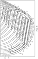
- Fig. 8 illustrates an example of the frame assembly 14 as it would be positioned within a body 16 (the body is depicted as transparent for clarity of illustration) and two (2) tooling elements 22 supporting two (2) frame elements 24 (e.g., keel frame elements 30) of the plurality of frame elements 24 (e.g., a plurality of keel frame elements 30 and side frame elements 32, 34) in position relative to the body 16 and the other frame elements 24. Only two (2) tooling elements 22 (e.g., of a lower tooling segment 46) are shown for clarity and one skilled in the art can appreciated that in use additional tooling elements 22 may be associated with each of the frame elements 24.
- two (2) tooling elements 22 e.g., of a lower tooling segment 46
- Fig. 9 illustrates an example of the frame assembly 14, as it would be positioned within a body 16 (the body is depicted as transparent for clarity of illustration) and a plurality of tooling elements 22 supporting a plurality of frame elements 24 (e.g., a plurality of second side frame elements 34) in position relative to the body 16 and the other frame elements 24.
- a plurality of tooling elements 22 e.g., of a second side tooling segment 50
- additional tooling elements 22 and tooling segments 18 may be associated with the frame elements 24.
- the longitudinal length of the tooling assembly 12, or each tooling segment 18 may be substantially equivalent to the longitudinal length of the body 16, such that frame elements 24 are spaced apart from the first end 40 to the second end 42 of the body 16.
- the number of frame elements 24 required to form the full frame assembly 14 for the body 16 may define the number of tooling elements 22 of the tooling assembly 12 or each tooling segment 18.
- the tooling elements 22 may be rigidly connected to adjacent (e.g., parallel) tooling elements 22, such as by a plurality of stringers 52.
- at least one stringer 52 may extend from the first end 54 to the second end 56 of each tooling segment 18 interconnecting each of the tooling elements 22.
- a plurality of stringer segments ( Fig. 8 ) may be interconnected between adjacent pairs of tooling elements 22.
- Each tooling segment 18 may be releasably connected to an adjacent tooling segment 18 along a longitudinal edge 58.
- a first edge stringer 64a may be connected along first ends 60a of the plurality of tooling elements 22 defining a first longitudinal edge 58a of a tooling segment 18.
- a second edge stringer 64b may be connected along longitudinally opposed second ends 60b of the plurality of tooling elements 22 defining a second longitudinal edge 58b of the tooling segment 18.
- Each of the edge stringers 64a, 64b may be configured to releasably connect to an adjacent edge stringer 64' of an adjacent tooling segment 18'.
- first end 60a and second end 60b of each tooling element 22 of a tooling segment 18 may be configured to releasably connect to adjacent ends 60' of each adjacent tooling element 22' of an adjacent tooling segment 18'.
- Each tooling segment 18 may be releasably connected by any suitable fastening mechanism 66.
- the fastening mechanism 66 may be configured to provide a quick connection and quick release of adjacent tooling segments 18.
- each tooling segment 18 may include at least one fastening mechanism 66 positioned along each longitudinal edge 58.
- the fastening mechanism 66 may include a flange disposed on each longitudinal edge 58. Each flange may include at least one through-hole aperture. Upon a pair of adjacent tooling segments 18 being positioned next to one another within the body 16, pairs of adjacent flanges may be positioned such that the aperture of each flange is aligned and configured to receive a fastener to connect the pair of adjacent tooling segments 18 together.
- the fastener may be a bolt, a pin, a spring pin, any other suitable fastening mechanism, or the like, without limitation.
- the fastening mechanism 66 may include a clamp or clip disposed on each longitudinal edge 58.
- pairs of adjacent clamps or clips may be aligned and configured to operably engage to one another to connect the pair of adjacent tooling segments 18 together.
- the tooling assembly 12 may be a one-piece (e.g., integral) ribcage tooling structure including a plurality of rigidly affixed ribcage tooling elements 22.
- each tooling element 22 may include a plurality of cradle assemblies 68.
- Each cradle assembly 68 may be configured to support and retain a portion of a corresponding frame element 24.
- the tooling assembly 12, or each tooling segment 18, may be configured to position the plurality of frame elements 24 at or near the correct engineering location.
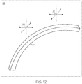
- the cradle assembly 68 may be movable in at least one direction with respect to the tooling element 22 and the surface (e.g., interior surface 38 or exterior surface 36) of the body 16 in order to further position the frame element 24 with respect to the body 16 (e.g., within acceptable tolerances to at least one engineering position 70 ( Fig. 12 ).
- the cradle assembly 68 may be movable at least three directions with respect to the tooling element 22 and the surface (e.g., interior surface 38 or exterior surface 36) of the body 16 to further position the frame element 24 with respect to the body 16 (e.g., within acceptable tolerances to at least one engineering location 70).
- the cradle assembly 68 may be configured to position the frame element 24 at the correct engineering location 70 for connection upon the surface (e.g., interior surface 38 or exterior surface 36) of the body 16.
- the cradle assembly 68 may be adjustably connected to the tooling element 22 such that the frame element 24 may be positioned at a correct X, Y, and Z location upon the body 16.
- the cradle assembly 68 may include a saddle 72 configured to support and retain the frame element 24.
- the saddle 72 may include a U-shaped member suitably sized to receive at least a portion of the frame element 24.
- the saddle 72 may include a clamping mechanism 74 configured to engageably retain the frame element 24 upon being received by the saddle 72.
- the clamping mechanism 74 may include at least one clamping member configured to contact a side of the frame element 24.
- the clamping member may include a spring pin biased in a closed position, a screw clamp, a set screw, or the like.
- the saddle 72 may be adjustably connected to a stanchion 76, for example to provide for motion in the Z-direction relative to the engineering location 70 ( Fig. 12 ).
- the stanchion 76 may include a tubular body configured to receive a stem of the saddle 72 and configured to provide linear movement of the saddle 72 in a telescoping manner.
- the saddle 72 may be releasably connected at varying positions with respect to the stanchion 76, for example by a pin or similar mechanical fastener.
- the stanchion 76 may be adjustably connected to the tooling element 22, for example to provide for motion in the X-direction and the Y-direction relative to the engineering location 70 ( Fig. 12 ).
- the stanchion 76 may be slidably connected (e.g., along a track) to the tooling element 22 to provide linear movement of the stanchion 76.
- the stanchion 76 may be pivotably connected to the tooling element 22 to provide rotational movement of the stanchion 76.
- the stanchion 76 may be releasably locked at varying positions with respect to the tooling element 22, for example by a pin or similar mechanical fastener.
- the body 16 may be supported by any conventional or suitable tooling or holding fixture 78 (see also Fig. 9 ).
- the body holding fixture 78 may stabilize and support the body 16 in a substantially horizontal position.
- the holding fixture 78 may be configured to support the body 16 in a substantially vertical position.
- the body holding fixture 78 may be configured to rotate the body 16 about the longitudinal axis A, such as during installation of the frame assembly 14, as will be described in more detail below.
- the positioning device 20 may be configured to support and hold the tooling assembly 12 at or near the engineered locations 70 ( Fig. 12 ) on the surface (e.g., interior surface 38 or exterior surface 36) of the body 16 ( Fig. 3 ) during installation of the frame assembly 14.
- the positioning device 20 may include a holding fixture 94 and a plurality of connection points each configured to secure the tooling segment 18.
- the holding fixture 94 may be configured to support and hold a particular configuration of tooling segment 18.
- the connection points may be positioned to engage the tooling segment 18 without interference with the adjustable positioning of the cradle assemblies 68.
- the positioning device 20 may be a manually moveable cart 82.
- the cart 82 may include a wheeled chassis 84.
- the holding fixture 94 may be attached to the chassis 84 and configured to position and support a single tooling segment 18 or a plurality of tooling segments 18 while being positioned with respect to the body 16 (e.g., inserted within the interior region 26 ( Fig. 2 ) of the body 16 or positioned proximate the exterior of the body 16).
- an installation platform 80 or similar support deck may be constructed around or adjacent to the body 16 to provide a support surface for movement of the positioning device 20 with respect to the body 16.
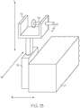
- the positioning device 20 may be a mechanical arm assembly 86.
- the arm assembly 86 may include a base 88 and at least one arm 90.
- the arm 90 may include the holding fixture 94 configured to support a single tooling segment 18 or a plurality of tooling segments 18 while being positioned with respect to the body 16 (e.g., inserted within the interior region 26 ( Fig. 2 ) of the body 16 or positioned proximate the exterior of the body 16).
- the arm 90 may be movable with respect to the base 88 for positioning the tooling segment 18 with respect to the body 16.
- the base 88 may include at least one drive mechanism (not shown) configured to move the arm 90 along an axis perpendicular to the longitudinal axis A (e.g., up and down) and to move the arm 90 along an axis parallel to the longitudinal axis A (e.g., in and out).
- the drive mechanism may be any suitable electrical drive, mechanical drive, hydraulic drive, pneumatic drive, or any other suitable type of driven mechanism, without limitation.
- the arm 90 may be manually positioned in any one of a variety of locations with respect to the base 88 and at least temporarily locked at that position, such as by a quick release fastener, clip, clamp, or any other suitable locking fastener or mechanism, without limitation.
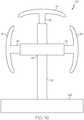
- the positioning device 20 may include an arm assembly 86 configured to support a plurality of tooling segments 18.
- the arm 90 may include a plurality of secondary arms 92.
- Each of the secondary arms 92 may include a holding fixture 94 configured to support a single tooling segment 18 or a plurality of tooling segments 18.
- the arm 90 may be movable with respect to the base 88 and each of the secondary arms 92 may be movable with respect to the arm 90 at a variety of locations.
- the base 88 may include at least one drive mechanism (not shown) configured to move the arm 90 along an axis perpendicular to the longitudinal axis A (e.g., up and down) and to move the arm 90 along an axis parallel to the longitudinal axis A (e.g., in and out).
- the drive mechanism may also be configured to move each of the secondary arms 92 along an axis perpendicular to the longitudinal axis A (e.g., toward and away from the surface (e.g., interior surface 38 or exterior surface 36) of the body 16).
- the tooling segment 18 may be attached (e.g., integral) to the arm 90 or to an end of each secondary arm 92.
- the holding fixture 94 may be eliminated.
- a body 16 may be provided.
- the body 16 may be a one-piece composite barrel.
- the body 16 may include a plurality of engineering locations 70 ( Fig. 12 ) for connection of a plurality of frame elements 24.
- a plurality of frame elements 24 defining a frame assembly 14 may be provided ( Fig. 3 ).
- the plurality of frame elements 24 may include a plurality of crown frame elements 28, a plurality of keel frame elements 30, a plurality of first side frame elements 32, and a plurality of second side frame elements 34 ( Fig. 4 ).
- a tooling assembly 12 ( Fig. 1 ) may be provided.
- the tooling assembly 12 may be a single integral tooling assembly 12 having a plurality of tooling elements 22 or may be a plurality of connectable tooling segments 18.
- Each tooling segment 18 may include a plurality of tooling elements 22.
- the tooling assembly 12 may include an upper segment 44, a lower segment 46, a first side segment 48, and a second side segment 50 ( Fig. 7 ).
- the tooling assembly 12 may be loaded (e.g., connected) onto the positioning device 20 ( Figs. 14-16 ).
- each tooling segment 18 may be loaded onto a dedicated positioning device 20 having a holding fixture 94 configured to hold that tooling segment 18.
- the integral or assembled tooling assembly 12 may be loaded onto a single positioning device having a plurality of holding fixtures each configured to hold a portion of the tooling assembly 12 (e.g., a tooling segment 18).
- the plurality of frame elements 24 may be loaded onto the tooling assembly 12.
- Each frame member 24 may be connected to a corresponding tooling element 22, such as at the cradle assemblies 68 ( Fig. 13 ).
- all of the frame elements 24 may be loaded onto the integral tooling assembly 12.
- a plurality of frame members 24 may be loaded on to each of the tooling segments 18.
- the plurality of crown frame elements 28 may be loaded on the tooling elements 22 of the upper segment 44
- the plurality of keel frame elements 30 may be loaded on the tooling elements 22 of the lower segment 46
- the plurality of first side frame elements 32 may be loaded on the tooling elements 22 of the first side segment 48
- the plurality of second side frame elements 34 may be loaded on the tooling elements 22 of the second side segment 50.
- the body 16 may be positioned at an initial position (e.g., by rotation of the body 16 with the assembly ring cart 78) suitable for placement of the tooling assembly 12 and frame assembly 14.
- the initial position may be a position such that the correct engineering locations 70 are proximate corresponding frame elements 24 upon the tooling segment 18 being positioned with respect to the surface of the body 16 (e.g., upon insertion of the tooling segment 18 within the body 16 or positioning of the tooling segment 18 outside of the body 16).
- the tooling assembly 12 ( Fig. 1 ), and the plurality of supported frame elements 24 ( Fig. 3 ) (e.g., at least a portion of the frame assembly 14), may be positioned with respect to the body 16 ( Fig. 2 ) (e.g., received within the interior region 26 of the body 16 or positioned about the exterior of the body 16).
- each tooling segment 18 ( Fig. 7 ) of the tooling assembly 12 may be sequentially or simultaneously inserted within the interior region 26 of the body 16 by the positioning device 20 ( Figs. 14 and 15 ).
- the body 16 may be repositioned (e.g., by rotation) as required to further align the frame elements 24 to the engineering locations 70 (e.g., within nominal engineering tolerances).
- GD&T Geometric Dimensioning and Tolerancing
- any other suitable technique or process for locating each of the frame elements 24 with respect to the body 16 may be used, without limitation.
- each tooling segment 18 may be temporarily secured in position with respect to the interior surface 38 of the body 16 (e.g., temporarily connected to the body 16).
- each tooling segment 18 may be temporarily secured in position with respect to the exterior surface 36 of the body 16 (e.g., temporarily connected to the body 16).
- the tooling assembly 12 may be disconnected from the positioning device 20.
- each tooling segment 18 may be detached from the holding fixture 94 ( Figs. 14 and 15 ) and the positioning device 20 may be removed from the body 16, as shown at block 120.
- each frame element 24 may be positioned with respect to the body 16, for example, to at least one corresponding engineering location 70 within nominal engineering tolerances ( Fig. 12 ).
- the frame elements 24 may be positioned with respect to the surface (e.g., interior surface 38 or exterior surface 36) of the body 16 ( Fig. 2 ) by the plurality of cradle assemblies 68 ( Fig. 11 ) disposed along each tooling element 22.
- Verification of the position of the frame elements 24 with respect to the corresponding engineering locations 70 may be performed using any suitable locating technique or process, for example by utilizing Determinate Assembly (DA) coordinated holes that line up from the body 16 to the frame elements 24. Gap checks may be performed and any excessive gaps (e.g., between the frame element 24 and the body 16) may be corrected (e.g., shimmed). All DA coordinating holes may be drilled and countersunk.
- DA Determinate Assembly
- each frame element 24 of the frame assembly 14 may be connected to the body 16 (e.g., at the engineering location 70) ( Fig. 12 ).
- the plurality of frame elements may be connected (e.g., spliced) together to form a full circumferential frame assembly 14 ( Fig. 3 ).
- the positioning device 20 may be repositioned proximate the tooling assembly 12 ( Fig. 1 ).
- the positioning device 20 ( Figs. 14-16 ) may be received (e.g., reinserted) within the body 16 ( Fig. 2 ) and the tooling assembly 12, or tooling segments 18 ( Fig. 7 ), may be reconnected to the positioning device 10 (e.g., the holding fixtures 94) ( Figs. 14-16 ), as shown at block 130.
- the tooling assembly 12, or the tooling segments 18, may be disconnected from the corresponding frame elements 24.
- the tooling assembly 12 may be removed from the body 16, as shown at block 134.
- each of the tooling segments 18 may sequentially or simultaneously be removed from the body 16.
- a first tooling segment 18 may be connected to the holding fixture 94 of a dedicated positioning device 20.
- a first plurality of frame elements 24 may be loaded onto the first tooling segment 18.
- the body 16 may be rotated to a first position to locate a first plurality of engineering locations 70.
- the first tooling segment 18 may be positioned relative to the body 16 (e.g., inserted, such as horizontally, within the body 16) to position the first plurality of frame elements 24 at or near the first plurality of engineering locations 70.
- the first tooling segment 18 of the connected first plurality of frame elements 24 may be temporarily connected to the body 16 and the first tooling segment 18 may be detached from the corresponding holding fixture 94. Once detached from the first tooling segment 18, the positioning device 20 may be removed from the body 16.
- a second tooling segment 18 may be connected to the holding fixture 94 of a dedicated positioning device 20.
- a second plurality of frame elements 24 may be loaded onto the second tooling segment 18'.
- the body 16 may be rotated to a second position to locate a second plurality of engineering locations 70.
- the second tooling segment 18 may be positioned relative to the body 16 (e.g., inserted, such as horizontally, within the body 16) to position the second plurality of frame elements 24 at or near the second plurality of engineering locations 70.
- the second tooling segment 18 of the connected second plurality of frame elements 24 may be temporarily connected to the body 16 and the second tooling segment 18 may be detached from the corresponding holding fixture 94.
- the second tooling segment 18 may be connected to the first tooling segment 18 (e.g., at the fastening mechanisms 66). Once detached from the second tooling segment 18, the positioning device 20 may be removed from the body 16.
- Additional tooling segments 18 may be loaded with additional pluralities of frame elements 24 and sequentially positioned relative to the body 16 in a substantially similar manner as previously described for the first tooling segment 18 and the second tooling segment 18. Positioning and connection of the tooling segments 18 may continue until the frame elements 24 form a full frame assembly 14.
- the plurality of frame members 24 may be positioned and fastened to the body 16 at the engineering locations 70 as a single frame assembly 14.
- each tooling segment 18 may be sequentially reconnected to its dedicated positioning device 20, disconnected from the adjacent tooling segments 18, disconnected from its associated plurality of frame elements 24, and removed from the body 16.
- a single assembled (e.g., integral) tooling assembly 12 may be loaded with a plurality of frame elements 24.
- the plurality of frame elements 24 may define the entire frame assembly 14.
- the tooling assembly 12 may be secured in a substantially vertical orientation by a holding fixture.
- the body 16 may be positioned in a substantially vertical orientation and positioned with respect to the tooling assembly 12 in order to position the frame elements 24 proximate the engineering locations 70 ( Fig. 12 ).
- the body 16 may be positioned (e.g., lowered or raised) over the tooling assembly 12 such that the tooling assembly 12 may be received within the body 16 and the frame assembly 14 may be located proximate the interior surface 38 of the body 16.
- the body 16 may be positioned (e.g., lowered or raised) within the tooling assembly 12 such that the body 16 may be received within the tooling assembly 12 and the frame assembly 14 may be located proximate the exterior surface 36 of the body 16.
- the frame elements 24 may be positioned and fastened in a substantially similar manner as previously described. Upon the plurality of frame elements 24 being fastened to the body 16, the tooling assembly 12 may be disconnected from the plurality of frame elements 24 and the body 16 may be removed from the tooling assembly 12.
- the frame assembly may be installed to the body 16 (e.g., to the interior 38 or exterior 36) using either horizontal or vertical fixture orientation and the method may use automated positioning devices 20 or manual positioning devices 20 for tooling assembly placement with respect to the body 16.
- the disclosed apparatus and method may provide for locating and installing a structural frame assembly to a fabricated composite one-piece body (e.g., fuselage).
- the apparatus and method may use tooling to locate each of a plurality of frame elements in a true position upon the body and relative to other frame elements for precise installation of the plurality of frame elements as a single assembly.
- the apparatus and method may solve for mislocation of the frame assembly relative to the fuselage, which may result in improvements to many secondary items, including an increase in initial quality and reduction in nonconformance.
- An apparatus for installation of a frame assembly to a body, said apparatus comprising: a tooling assembly configured to support a frame assembly, said tooling assembly being positioned proximate a body; wherein said frame assembly is positioned with respect to said body at a plurality of predetermined engineering locations.
- Said tooling assembly may comprise a plurality of interconnected tooling elements, each tooling element of said plurality of tooling elements being configured to support one frame element of a plurality of frame elements defining said frame assembly.
- Said tooling assembly may be configured to match at least a portion of a perimeter shape of said body, such that each frame element of said plurality of frame elements is positioned proximate a surface of said body at said predetermined engineering locations upon said tooling assembly being positioned proximate said body.
- Each tooling element of said plurality of tooling elements may comprise at least one cradle assembly, said cradle assembly being configured to engage a portion of said one frame element and hold said one frame element in a stabile position.
- Said cradle assembly may be configured to adjust a position of said one frame element with respect to each predetermined engineering location of said plurality of predetermined engineering locations.
- Said tooling assembly may comprise a plurality of tooling segments, each of said tooling segments comprising a plurality of interconnected tooling elements, each tooling element of said plurality of tooling elements being configured to support one frame element of a plurality of frame elements defining said frame assembly.
- Each tooling segment of said plurality of tooling segments may be configured to match a perimeter shape of at least a portion of said body, such that each frame element of said plurality of frame elements is positioned proximate a surface of said body at said predetermined engineering location upon said tooling assembly being positioned proximate said body.
- Each tooling segment of said plurality of tooling segments may be configured to releasably connect to an adjacent tooling segment of said plurality of tooling segments.
- Each tooling element of said plurality of tooling elements of each tooling segment may comprise at least one cradle assembly, said cradle assembly being configured to engage a portion of said one frame element and hold said one frame element in a stabile position.
- Said cradle assembly may be configured to adjust a position of said one frame element with respect to each predetermined engineering location of said plurality of predetermined engineering locations.
- Said tooling assembly may comprise a plurality of cradle assemblies, each cradle assembly of said plurality of cradle assemblies being configured to engage a portion of said frame assembly and hold said frame assembly in a stabile position.
- Each cradle assembly of said plurality of cradle assemblies may be movable in at least one direction with respect to said tooling assembly.
- Each cradle assembly of said plurality of cradle assemblies may be movable in at least three directions with respect to said tooling assembly.
- the apparatus may further comprise at least one positioning device configured to position said tooling assembly with respect to said body, such that said tooling assembly is positioned proximate a surface of said body proximate a predetermined engineering location upon.
- An apparatus for installation of a frame assembly to a body, said apparatus comprising: a tooling assembly comprising a plurality of tooling segments configured to support a plurality of frame elements defining a frame assembly, each tooling segment of said plurality of tooling segments comprising a plurality of tooling elements, and each tooling element of said plurality of tooling elements being configured to support one frame element of said plurality of frame elements; and at least one positioning device configured to support each tooling segment of said plurality of tooling segments and position each tooling segment with respect to a surface of a body; wherein each frame element of said plurality of frame elements is positioned with respect to said body at a predetermined engineering location to form said frame assembly.
- Each tooling element of said plurality of tooling elements may comprise at least one cradle assembly; wherein said cradle assembly may be configured to engage a portion of said one frame element and hold said one frame element in a stabile position; and wherein said cradle assembly may be configured to adjust a position of said one frame element with respect to said predetermined engineering location.
- Said positioning device may comprise a holding fixture, said holding fixture being configured to retain one tooling segment of said plurality of tooling segments.
- a method is disclosed for installation of a frame assembly to a body, said method comprising the steps of: providing a body; providing a plurality of frame elements defining a frame assembly; providing a tooling assembly, said tooling assembly being configured to support said plurality of frame elements; loading said plurality of frame elements onto said tooling assembly; positioning said tooling assembly proximate said body such that said plurality of frame elements are positioned with respect to a surface of said body proximate a plurality of engineering locations; fastening said plurality of frame elements to said body at said plurality of engineering locations; and removing said tooling assembly.
- Said positioning step may comprise horizontally moving said tooling assembly with respect to said body.
- Said positioning step may comprise vertically moving said body with respect to said tooling assembly.
Landscapes
- Engineering & Computer Science (AREA)
- Transportation (AREA)
- Manufacturing & Machinery (AREA)
- Aviation & Aerospace Engineering (AREA)
- Remote Sensing (AREA)
- Mechanical Engineering (AREA)
- Moulding By Coating Moulds (AREA)
- Automatic Assembly (AREA)
Description
- Some modern commercial aircraft include a barrel fabricated from a one-piece composite body. In order to provide sufficient structural rigidity to the body, a frame assembly must be fastened to the body. The frame assembly may be defined by a plurality of individual frame elements. The frame elements must not only be fastened at correct predetermined locations upon the body, but must also be fastened to other adjacent frame elements.
- Individual placement and fastening of frame elements may lead to frame assembly mislocation. Accordingly, undesired stresses may be applied to the body and the frame elements as a result of mislocation of the fastened frame assembly. Additionally, various other non-conformance issues may arise from mislocation of the frame assembly. For example, secondary interior structures, such as flooring, may not be properly installed as a result of mislocation. Thus, custom parts must be designed, fabricated, and installed resulting in significant cost associated with rework, repair, replacement parts, and out of sequence work.
- Accordingly, those skilled in the art continue with research and development efforts in the field of structural frame assemblies, including the installation of a plurality of frame elements defining a frame assembly relative to a one-piece body.
-
US 2012/0043008 discloses a method for joining, by adhesive bonding, at least two large joining partners in vehicle construction, in particular in aircraft construction, the method comprising the following steps: detecting the geometric data of the joining partners in an automated manner, detecting the joint gap dimensions of the joining partners from the geometric data, applying adhesive to one or both joint faces of the two joining partners to be joined as a function of the joint gap dimensions, joining the joining partners in the joining position, and sequentially applying joining pressure to the joint faces along the joint gap to bring the joining partners into the final joining position. -
US 2012/0066907 discloses a method of making an aircraft in which a mandrel is caused to pass through frames carried by a magazine; and as it passes through, the frames are transferred onto the mandrel. -
US 2010/0181426 discloses a aircraft fuselage structure with frames running in the circumferential direction, stringers running in the longitudinal direction and a skin which is arranged thereon and outwardly seals the aircraft fuselage in a compression-proof manner. According to the invention, it is provided that the aircraft fuselage structure contains prefabricated integral units (10) which each run in the circumferential direction of a fuselage segment and in which the frame (11) of a fuselage segment and connecting elements (17, 18) for connection to skin elements (20) comprising stringers (22) and skin (21) are formed. -
US 5,709,769 discloses a duct assembly system for the shaping and support of skins against a bulkhead, including an articulating skin expanding member conforming, in an extended position, to a cross section of the bulkhead, and a support means attached to the expanding member for insertion of the expanding member into the skins and alignment of the expanding member adjacent to the bulkhead. -
DE10030499A1 discloses an assembly aid which has curved carrier elements (10) and longitudinal carriers. The aid basically consists of an assembly axis (8) extending in the longitudinal direction of the carrier cell, and a guide (13) attached to this axis with an arm (17) carrying positioning devices (18, 19) to adjust the position of the carrying elements. - The apparatus according to the invention is claimed in claim 1. The method according to the invention is claimed in
claim 10. - Other embodiments of the disclosed apparatus and method for installation of a frame assembly to a body will become apparent from the following detailed description, the accompanying drawings and the appended claims.
-
-
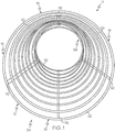
Fig. 1 is a front elevational view of one embodiment of the disclosed apparatus for installation of a frame assembly to a body; -
Fig. 2 is a front elevational view of one embodiment of the disclosed body; -
Fig. 3 is a front elevational view of one embodiment of the disclosed structural frame assembly; -
Fig. 4 is an exploded front elevational view of a portion of the frame assembly ofFig. 3 ; -
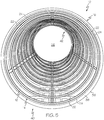
Fig. 5 is a front elevational view of the apparatus ofFig. 1 illustrating installation of the structural frame assembly ofFig. 3 ; -
Fig. 6 is a front elevational view of one embodiment of the disclosed frame assembly ofFig. 3 connected to the apparatus ofFig. 1 ; -
Fig. 7 is an exploded front elevational view of the apparatus ofFig. 1 ; -
Fig. 8 is a front and side perspective view of the apparatus ofFig. 1 ; -
Fig. 9 is another front and side perspective view of the apparatus ofFig. 1 ; -
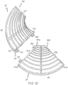
Fig. 10 is a front elevational view of a pair of tooling segments of the disclosed apparatus ofFig. 1 ; -
Fig. 11 is a perspective side view of the tooling element of the disclosed apparatus; -
Fig. 12 is a schematic view of the position of the frame element with respect to the body; -
Fig. 13 is a partial perspective view of a tooling element and a cradle assembly; -
Fig. 14 is an illustration of an example method of installing the frame assembly relative to the body using the disclosed apparatus; -
Fig. 15 is an illustration of another example method of installing the frame assembly relative to the body using the disclosed apparatus; -
Fig. 16 is a front view of one embodiment of the installation device of the disclosed apparatus; and -
Fig. 17 is a flow diagram of the disclosed method for installing the frame assembly relative to a body. - The following detailed description refers to the accompanying drawings, which illustrate specific embodiments of the disclosure. Like reference numerals may refer to the same element or component in the different drawings.
- Referring to
Fig. 1 , the disclosed apparatus for installation of a frame assembly to a body, generally designated 10, may include atooling assembly 12 configured to support a structural frame assembly 14 (Fig. 3 ) for connection to a surface of a body 16 (Fig. 2 ). Thetooling assembly 12 may include either a single or segmented piece of machine tooling having a ribcage design configured to hold theframe assembly 14 in true position within engineering tolerance for connection to thebody 16. Thetooling assembly 12 may locate theframe assembly 14 or a portion of the frame assembly 14 (e.g., a frame segment 18 (Fig. 7 )) proximate the surface of thebody 16. For example, thetooling assembly 12 and supportedframe assembly 14 may be received within thebody 16 such that theframe assembly 14 is proximate aninterior surface 38 of the body 16 (Fig. 2 ). As another example, thetooling assembly 12 and supportedframe assembly 14 may be positioned about an exterior of thebody 16 such that theframe assembly 14 is proximate anexterior surface 36 of the body 16 (Fig. 2 ). - As will be described in further detail herein, the disclosed
apparatus 10 may include at least onetooling assembly 12 and at least one positioning device 20 (Figs. 14-16 ). Thepositioning device 20 may be configured to move and support thetooling assembly 12 with respect to the surface of thebody 16. In an example implementation, thepositioning device 20 may be configured to support thetooling assembly 12 during insertion of thetooling assembly 12 and theframe assembly 14 proximate the interior surface 38 (e.g., within an interior 26) of the body 16 (Fig. 3 ). In another example implementation, thepositioning device 20 may be configured to support thetooling assembly 12 during positioning of thetooling assembly 12 and theframe assembly 14 proximate theexterior surface 36 of thebody 16. For example, thepositioning device 20 may be a cart 82 (Fig. 14 ) or an arm assembly 86 (Figs. 15 and16 ). - Referring to
Fig. 2 , thebody 16 may be any shell forming an outer surface (e.g., skin) of a manufactured structure or component. For example, thebody 16 may be a unitary (e.g., one-piece) member fabricated of a composite material. Thebody 16 may have any cross-sectional perimeter shape. For example, thebody 16 may have a circular cross-sectional perimeter shape, an ovular cross-sectional perimeter shape, a rectangular cross-sectional perimeter shape, or may have any other symmetric or asymmetric geometric cross-sectional shape. -
Fig. 2 illustrates an example construction of thebody 16 depicted prior to installation (e.g., insertion and connection) of theframe assembly 14. Thebody 16 may include afirst end 40, asecond end 42, anexterior surface 36, and aninterior surface 38. Thesecond end 42 may be longitudinally spaced away from thefirst end 40. Thebody 16 may also have any overall shape (e.g., longitudinal shape) having a hollowinterior region 26 configured to receive theframe assembly 14. A continuous wall of thebody 16 may extend from proximate thefirst end 40 to proximate thesecond end 42 to define the shape of thebody 16 and theinterior region 26. - For example, as illustrated, the
body 16 may be generally conical-shaped having a constant cross-sectional perimeter shape with a varying perimeter diameter along the longitudinal axis A (Fig. 15 ). As another example, thebody 16 may be generally cylindrical-shaped having a constant cross-sectional perimeter shape with a constant perimeter diameter along the longitudinal axis A (Fig. 15 ). As another example, thebody 16 may be generally rectangular-shaped having a square cross-sectional perimeter shape. As still another example, thebody 16 may have a variable shape with a variable cross-sectional perimeter shape along the longitudinal axis A. - As a specific non-limiting example embodiment, the
body 16 may be a barrel section (e.g., fuselage) of an aircraft having a substantially cylindrical or conical shape. The one-piece body 16 may include various cutouts, apertures, and the like configured as various access openings (e.g., window openings). One skilled in the art can appreciate that thebody 16 may also be the barrel section of a rocket, the fuselage or tail boom of a helicopter, the shell body of a motor vehicle, the shell body of a boat, or other vehicular applications. One skilled in the art can also appreciate that the disclosedinstallation apparatus 10 configured to locate and install at least one frame assembly to a body (e.g., to an interior surface or to an exterior surface) may be utilized in other non-vehicular applications, such as industrial applications (e.g., structures), without limitation. - Referring to
Fig. 3 , theframe assembly 14 may include a plurality ofstructural frame elements 24. Theframe assembly 14 may define the framework (e.g., load bearing frame) of the manufactured structure or component (e.g., aircraft fuselage). For example, each of theframe elements 24 may be connected (e.g., fastened) to theinterior surface 38 of the body 16 (Fig. 2 ) at a predetermined (e.g., engineering) location 70 (Fig. 12 ) upon thebody 16. As another example, each of theframe elements 24 may be connected (e.g., fastened) to theexterior surface 36 of the body 16 (Fig. 2 ) at a predetermined (e.g., engineering) location 70 (Fig. 12 ) upon thebody 16. Eachframe element 24 may be connected to at least onelocation 70 upon the surface of thebody 16, such as by mechanical fasteners, chemical bonding, welding, soldering, or any other suitable attachment or assembly technique. - The present disclosure illustrates one
frame assembly 14, formed by a plurality offrame elements 24, being installed (e.g., received and connected) within thebody 16. However, one skilled in the art can appreciate that a plurality ofbodies 16 may be connected to form a final structure or component (e.g., aircraft fuselage) and eachbody 16 of the plurality ofbodies 16 may include aframe assembly 14 installed within by the disclosedapparatus 10, in accordance with the present disclosure, without limitation. It can also be appreciated that one ormore frame assemblies 14 may be installed (e.g., positioned and connected) to an exterior of thebody 16. -
Fig. 3 illustrates an assembledframe assembly 14 with thebody 16 removed for clarity. The assembledframe assembly 14 may have an overall shape (e.g., cross-sectional perimeter shape and longitudinal shape) substantially equivalent to that of thebody 16 whether installed and connected to theinterior surface 38 or theexterior surface 36 - Referring to
Fig. 4 , in accordance with the example aircraft embodiment, the plurality ofstructural frame elements 24 may include a crown (e.g., upper)frame element 28, a keel (e.g., lower)frame element 30, a first (e.g., left)side element 32, and a second (e.g., right)side element 34. A plurality of each type offrame element Fig. 3 ). One skilled in the art can appreciate other types, configurations, and quantities offrame elements 24 may be used depending upon the final manufactured structure or component and whether the frame assembly 2 is installed to the interior or exterior of thebody 16. - Referring to
Fig. 5 , the plurality offrame elements 24 may each be supported by thetooling assembly 12 for installation to the body 16 (e.g., to theinterior surface 38 or the exterior surface 36). Thetooling assembly 12 may have an overall shape (e.g., cross-sectional perimeter shape and longitudinal shape) substantially equivalent to that of thebody 16. For example, thetooling assembly 12 may be suitably sized to be received within theinterior region 26 of thebody 16 such that the supportedframe assembly 14 is proximate theinterior surface 38 of thebody 16. Thetooling assembly 12, with theframe assembly 14 supported, may be inserted through an open end (e.g., the first end 40) by the positioning device 20 (Figs. 14 and15 ). As another example, thetooling assembly 12 may be suitably sized to surround an exterior region of thebody 16 such that the supportedframe assembly 14 is proximate theexterior surface 36 of thebody 16. Thetooling assembly 12, with theframe assembly 14 supported, may be positioned alongside thebody 16 by thepositioning device 20. - Referring to
Fig. 5 , thetooling assembly 12 may locate each of theframe elements 24 in a true position (e.g., the proper placement of theframe element 24 given an acceptable amount of variance) relative to thebody 16 and theother frame elements 24. Any differences between the location of theframe assembly 14, or anyindividual frame element 24, and the shape of the body 16 (e.g., gaps between the frame element and the interior surface of the one-piece fuselage) can be addressed prior to permanent installation of theframe elements 24. - Referring to
Figs. 1 ,2 ,3 and7 , thetooling assembly 12 may include a first end 54 (Fig. 1 ) configured to be located proximate thefirst end 40 of the body 16 (Fig. 2 ) and a longitudinally opposed second end 56 (Fig. 1 ) configured to the located proximate thesecond end 42 of thebody 16. Theribcage tooling assembly 12 may include a plurality of ribcage tooling segments 18 (Fig 7 ). Eachtooling segment 18 may be releasably connected to anadjacent tooling segment 18 to form thetooling assembly 12. Eachtooling segment 18 may be configured to support and retain a plurality of frame elements 24 (Fig. 3 ). Thus, the plurality oftooling segments 18 may be arranged and connected to form an assembledtooling assembly 12 having a shape corresponding to the shape of theframe assembly 14 and to thebody 16. - For example, the plurality of
framework segments 18 may include anupper segment 44 configured to support and retain a plurality ofcrown frame elements 28, alower segment 46 configured to support and retain a plurality ofkeel frame elements 30, a first (e.g., left)side segment 48 configured to support and retain a plurality of firstside frame elements 32, and a second (e.g., right)side segment 50 configured to support and retain a plurality of secondside frame elements 34. - Referring to
Fig. 7 , eachtooling segment 18 may include a plurality ofribcage tooling elements 22 extending from thefirst end 54 to thesecond end 56. Eachtooling segment 18 may be configured to support and retain asingle frame element 24 of the frame assembly 14 (Figs. 3 and4 ). For example, eachtooling element 22 may be sized and shaped to substantially match the size and shape of acorresponding frame element 24 and a corresponding portion of thebody 16. - Referring to
Figs. 8 and9 , generally eachframe element 24 of the plurality offrame elements 24 supported and retained by a correspondingtooling segment 18 may be located at a predetermined position (e.g., at engineering locations 70 (Fig. 12 )) with respect to the interior surface 38 (Fig. 11 ) or theexterior 36 of the body 16 (Fig. 2 ) and with respect to theother frame elements 24. -
Fig. 8 illustrates an example of theframe assembly 14 as it would be positioned within a body 16 (the body is depicted as transparent for clarity of illustration) and two (2)tooling elements 22 supporting two (2) frame elements 24 (e.g., keel frame elements 30) of the plurality of frame elements 24 (e.g., a plurality ofkeel frame elements 30 andside frame elements 32, 34) in position relative to thebody 16 and theother frame elements 24. Only two (2) tooling elements 22 (e.g., of a lower tooling segment 46) are shown for clarity and one skilled in the art can appreciated that in useadditional tooling elements 22 may be associated with each of theframe elements 24. -
Fig. 9 illustrates an example of theframe assembly 14, as it would be positioned within a body 16 (the body is depicted as transparent for clarity of illustration) and a plurality oftooling elements 22 supporting a plurality of frame elements 24 (e.g., a plurality of second side frame elements 34) in position relative to thebody 16 and theother frame elements 24. A plurality of tooling elements 22 (e.g., of a second side tooling segment 50) are shown for clarity and one skilled in the art can appreciated that in useadditional tooling elements 22 andtooling segments 18 may be associated with theframe elements 24. - It can be appreciated that the longitudinal length of the
tooling assembly 12, or eachtooling segment 18, may be substantially equivalent to the longitudinal length of thebody 16, such thatframe elements 24 are spaced apart from thefirst end 40 to thesecond end 42 of thebody 16. The number offrame elements 24 required to form thefull frame assembly 14 for thebody 16 may define the number oftooling elements 22 of thetooling assembly 12 or eachtooling segment 18. - Referring back to
Fig. 7 , thetooling elements 22 may be rigidly connected to adjacent (e.g., parallel)tooling elements 22, such as by a plurality ofstringers 52. In an example construction, at least onestringer 52 may extend from thefirst end 54 to thesecond end 56 of eachtooling segment 18 interconnecting each of thetooling elements 22. In another example construction, a plurality of stringer segments (Fig. 8 ) may be interconnected between adjacent pairs oftooling elements 22. Eachtooling segment 18 may be releasably connected to anadjacent tooling segment 18 along alongitudinal edge 58. - Referring to
Fig. 10 , in an example construction, afirst edge stringer 64a may be connected along first ends 60a of the plurality oftooling elements 22 defining a firstlongitudinal edge 58a of atooling segment 18. A second edge stringer 64b may be connected along longitudinally opposed second ends 60b of the plurality oftooling elements 22 defining a secondlongitudinal edge 58b of thetooling segment 18. Each of theedge stringers 64a, 64b may be configured to releasably connect to an adjacent edge stringer 64' of an adjacent tooling segment 18'. - In another example construction, the
first end 60a andsecond end 60b of eachtooling element 22 of atooling segment 18 may be configured to releasably connect to adjacent ends 60' of each adjacent tooling element 22' of an adjacent tooling segment 18'. - Each
tooling segment 18 may be releasably connected by anysuitable fastening mechanism 66. Thefastening mechanism 66 may be configured to provide a quick connection and quick release ofadjacent tooling segments 18. For example, eachtooling segment 18 may include at least onefastening mechanism 66 positioned along eachlongitudinal edge 58. - As an example construction, the
fastening mechanism 66 may include a flange disposed on eachlongitudinal edge 58. Each flange may include at least one through-hole aperture. Upon a pair ofadjacent tooling segments 18 being positioned next to one another within thebody 16, pairs of adjacent flanges may be positioned such that the aperture of each flange is aligned and configured to receive a fastener to connect the pair ofadjacent tooling segments 18 together. The fastener may be a bolt, a pin, a spring pin, any other suitable fastening mechanism, or the like, without limitation. - As another example construction, the
fastening mechanism 66 may include a clamp or clip disposed on eachlongitudinal edge 58. Upon a pair ofadjacent tooling segments 18 being positioned next to one another within thebody 16, pairs of adjacent clamps or clips may be aligned and configured to operably engage to one another to connect the pair ofadjacent tooling segments 18 together. - In another embodiment, the
tooling assembly 12 may be a one-piece (e.g., integral) ribcage tooling structure including a plurality of rigidly affixedribcage tooling elements 22. - Referring to
Fig. 11 , eachtooling element 22 may include a plurality ofcradle assemblies 68. Eachcradle assembly 68 may be configured to support and retain a portion of acorresponding frame element 24. Thetooling assembly 12, or eachtooling segment 18, may be configured to position the plurality offrame elements 24 at or near the correct engineering location. In an example construction, thecradle assembly 68 may be movable in at least one direction with respect to thetooling element 22 and the surface (e.g.,interior surface 38 or exterior surface 36) of thebody 16 in order to further position theframe element 24 with respect to the body 16 (e.g., within acceptable tolerances to at least one engineering position 70 (Fig. 12 ). In another example construction, thecradle assembly 68 may be movable at least three directions with respect to thetooling element 22 and the surface (e.g.,interior surface 38 or exterior surface 36) of thebody 16 to further position theframe element 24 with respect to the body 16 (e.g., within acceptable tolerances to at least one engineering location 70). - Referring to
Fig. 12 , thecradle assembly 68 may be configured to position theframe element 24 at thecorrect engineering location 70 for connection upon the surface (e.g.,interior surface 38 or exterior surface 36) of thebody 16. For example, thecradle assembly 68 may be adjustably connected to thetooling element 22 such that theframe element 24 may be positioned at a correct X, Y, and Z location upon thebody 16. - Referring to
Fig. 13 , in an example construction, thecradle assembly 68 may include asaddle 72 configured to support and retain theframe element 24. For example, thesaddle 72 may include a U-shaped member suitably sized to receive at least a portion of theframe element 24. Thesaddle 72 may include aclamping mechanism 74 configured to engageably retain theframe element 24 upon being received by thesaddle 72. Theclamping mechanism 74 may include at least one clamping member configured to contact a side of theframe element 24. For example, the clamping member may include a spring pin biased in a closed position, a screw clamp, a set screw, or the like. - The
saddle 72 may be adjustably connected to astanchion 76, for example to provide for motion in the Z-direction relative to the engineering location 70 (Fig. 12 ). Thestanchion 76 may include a tubular body configured to receive a stem of thesaddle 72 and configured to provide linear movement of thesaddle 72 in a telescoping manner. Thesaddle 72 may be releasably connected at varying positions with respect to thestanchion 76, for example by a pin or similar mechanical fastener. - The
stanchion 76 may be adjustably connected to thetooling element 22, for example to provide for motion in the X-direction and the Y-direction relative to the engineering location 70 (Fig. 12 ). As an example, thestanchion 76 may be slidably connected (e.g., along a track) to thetooling element 22 to provide linear movement of thestanchion 76. As another example, thestanchion 76 may be pivotably connected to thetooling element 22 to provide rotational movement of thestanchion 76. Thestanchion 76 may be releasably locked at varying positions with respect to thetooling element 22, for example by a pin or similar mechanical fastener. - Referring to
Figs. 14 and15 , prior to installation of theframe assembly 14 to thebody 16, thebody 16 may be supported by any conventional or suitable tooling or holding fixture 78 (see alsoFig. 9 ). Thebody holding fixture 78 may stabilize and support thebody 16 in a substantially horizontal position. Alternatively, the holdingfixture 78 may be configured to support thebody 16 in a substantially vertical position. In certain embodiments, thebody holding fixture 78 may be configured to rotate thebody 16 about the longitudinal axis A, such as during installation of theframe assembly 14, as will be described in more detail below. - The
positioning device 20 may be configured to support and hold thetooling assembly 12 at or near the engineered locations 70 (Fig. 12 ) on the surface (e.g.,interior surface 38 or exterior surface 36) of the body 16 (Fig. 3 ) during installation of theframe assembly 14. Thepositioning device 20 may include a holdingfixture 94 and a plurality of connection points each configured to secure thetooling segment 18. The holdingfixture 94 may be configured to support and hold a particular configuration oftooling segment 18. The connection points may be positioned to engage thetooling segment 18 without interference with the adjustable positioning of thecradle assemblies 68. - As shown in
Fig. 14 , in an example embodiment, thepositioning device 20 may be a manuallymoveable cart 82. Thecart 82 may include awheeled chassis 84. The holdingfixture 94 may be attached to thechassis 84 and configured to position and support asingle tooling segment 18 or a plurality oftooling segments 18 while being positioned with respect to the body 16 (e.g., inserted within the interior region 26 (Fig. 2 ) of thebody 16 or positioned proximate the exterior of the body 16). In an example method for installing the frame assembly 14 (Fig. 3 ) to the body 16 (Fig. 6 ), aninstallation platform 80 or similar support deck may be constructed around or adjacent to thebody 16 to provide a support surface for movement of thepositioning device 20 with respect to thebody 16. - As shown in
Fig. 15 , in another example embodiment, thepositioning device 20 may be amechanical arm assembly 86. Thearm assembly 86 may include abase 88 and at least onearm 90. Thearm 90 may include the holdingfixture 94 configured to support asingle tooling segment 18 or a plurality oftooling segments 18 while being positioned with respect to the body 16 (e.g., inserted within the interior region 26 (Fig. 2 ) of thebody 16 or positioned proximate the exterior of the body 16). Thearm 90 may be movable with respect to thebase 88 for positioning thetooling segment 18 with respect to thebody 16. For example, thebase 88 may include at least one drive mechanism (not shown) configured to move thearm 90 along an axis perpendicular to the longitudinal axis A (e.g., up and down) and to move thearm 90 along an axis parallel to the longitudinal axis A (e.g., in and out). The drive mechanism may be any suitable electrical drive, mechanical drive, hydraulic drive, pneumatic drive, or any other suitable type of driven mechanism, without limitation. As another example, thearm 90 may be manually positioned in any one of a variety of locations with respect to thebase 88 and at least temporarily locked at that position, such as by a quick release fastener, clip, clamp, or any other suitable locking fastener or mechanism, without limitation. - Referring to
Fig. 16 , in another embodiment, thepositioning device 20 may include anarm assembly 86 configured to support a plurality oftooling segments 18. Thearm 90 may include a plurality ofsecondary arms 92. Each of thesecondary arms 92 may include a holdingfixture 94 configured to support asingle tooling segment 18 or a plurality oftooling segments 18. Thearm 90 may be movable with respect to thebase 88 and each of thesecondary arms 92 may be movable with respect to thearm 90 at a variety of locations. For example, thebase 88 may include at least one drive mechanism (not shown) configured to move thearm 90 along an axis perpendicular to the longitudinal axis A (e.g., up and down) and to move thearm 90 along an axis parallel to the longitudinal axis A (e.g., in and out). The drive mechanism may also be configured to move each of thesecondary arms 92 along an axis perpendicular to the longitudinal axis A (e.g., toward and away from the surface (e.g.,interior surface 38 or exterior surface 36) of the body 16). - In another embodiment, the
tooling segment 18 may be attached (e.g., integral) to thearm 90 or to an end of eachsecondary arm 92. In such a configuration, the holdingfixture 94 may be eliminated. - Referring to
Fig. 17 , also disclosed is a method, generally designated 100, for installing a frame assembly to abody 16. As shown atblock 102, abody 16 may be provided. In accordance with the aircraft example, thebody 16 may be a one-piece composite barrel. Thebody 16 may include a plurality of engineering locations 70 (Fig. 12 ) for connection of a plurality offrame elements 24. - As shown at
block 104, a plurality offrame elements 24 defining aframe assembly 14 may be provided (Fig. 3 ). In accordance with the aircraft example, the plurality offrame elements 24 may include a plurality ofcrown frame elements 28, a plurality ofkeel frame elements 30, a plurality of firstside frame elements 32, and a plurality of second side frame elements 34 (Fig. 4 ). - As shown at
block 106, a tooling assembly 12 (Fig. 1 ) may be provided. Thetooling assembly 12 may be a singleintegral tooling assembly 12 having a plurality oftooling elements 22 or may be a plurality ofconnectable tooling segments 18. Eachtooling segment 18 may include a plurality oftooling elements 22. In accordance with the aircraft example, thetooling assembly 12 may include anupper segment 44, alower segment 46, afirst side segment 48, and a second side segment 50 (Fig. 7 ). - As shown at
block 108, thetooling assembly 12 may be loaded (e.g., connected) onto the positioning device 20 (Figs. 14-16 ). For example, eachtooling segment 18 may be loaded onto adedicated positioning device 20 having a holdingfixture 94 configured to hold thattooling segment 18. As another example, the integral or assembledtooling assembly 12 may be loaded onto a single positioning device having a plurality of holding fixtures each configured to hold a portion of the tooling assembly 12 (e.g., a tooling segment 18). - As shown at
block 110, the plurality offrame elements 24 may be loaded onto thetooling assembly 12. Eachframe member 24 may be connected to acorresponding tooling element 22, such as at the cradle assemblies 68 (Fig. 13 ). In one example method, all of theframe elements 24 may be loaded onto theintegral tooling assembly 12. In another example method, a plurality offrame members 24 may be loaded on to each of thetooling segments 18. In accordance with the aircraft example, the plurality ofcrown frame elements 28 may be loaded on thetooling elements 22 of theupper segment 44, the plurality ofkeel frame elements 30 may be loaded on thetooling elements 22 of thelower segment 46, the plurality of firstside frame elements 32 may be loaded on thetooling elements 22 of thefirst side segment 48, and the plurality of secondside frame elements 34 may be loaded on thetooling elements 22 of thesecond side segment 50. - As shown at
block 112, thebody 16 may be positioned at an initial position (e.g., by rotation of thebody 16 with the assembly ring cart 78) suitable for placement of thetooling assembly 12 andframe assembly 14. For example, the initial position may be a position such that thecorrect engineering locations 70 are proximatecorresponding frame elements 24 upon thetooling segment 18 being positioned with respect to the surface of the body 16 (e.g., upon insertion of thetooling segment 18 within thebody 16 or positioning of thetooling segment 18 outside of the body 16). - As shown at
block 114, the tooling assembly 12 (Fig. 1 ), and the plurality of supported frame elements 24 (Fig. 3 ) (e.g., at least a portion of the frame assembly 14), may be positioned with respect to the body 16 (Fig. 2 ) (e.g., received within theinterior region 26 of thebody 16 or positioned about the exterior of the body 16). In accordance with the aircraft example, each tooling segment 18 (Fig. 7 ) of thetooling assembly 12 may be sequentially or simultaneously inserted within theinterior region 26 of thebody 16 by the positioning device 20 (Figs. 14 and15 ). Thebody 16 may be repositioned (e.g., by rotation) as required to further align theframe elements 24 to the engineering locations 70 (e.g., within nominal engineering tolerances). For example, Geometric Dimensioning and Tolerancing (GD&T) may be used to locate each of theframe elements 24 to theengineering locations 70 within nominal engineering tolerances. However, any other suitable technique or process for locating each of theframe elements 24 with respect to thebody 16 may be used, without limitation. - As shown at
block 116, thetooling assembly 12 and at least a portion of theframe assembly 14, may be temporarily secured to a position upon the body 16 (Fig. 5 ). For example, eachtooling segment 18 may be temporarily secured in position with respect to theinterior surface 38 of the body 16 (e.g., temporarily connected to the body 16). As another example, eachtooling segment 18 may be temporarily secured in position with respect to theexterior surface 36 of the body 16 (e.g., temporarily connected to the body 16). - Also shown at block 118, the
tooling assembly 12 may be disconnected from thepositioning device 20. For example, eachtooling segment 18 may be detached from the holding fixture 94 (Figs. 14 and15 ) and thepositioning device 20 may be removed from thebody 16, as shown atblock 120. - As shown at
block 122, eachframe element 24 may be positioned with respect to thebody 16, for example, to at least onecorresponding engineering location 70 within nominal engineering tolerances (Fig. 12 ). For example, theframe elements 24 may be positioned with respect to the surface (e.g.,interior surface 38 or exterior surface 36) of the body 16 (Fig. 2 ) by the plurality of cradle assemblies 68 (Fig. 11 ) disposed along eachtooling element 22. Verification of the position of theframe elements 24 with respect to thecorresponding engineering locations 70 may be performed using any suitable locating technique or process, for example by utilizing Determinate Assembly (DA) coordinated holes that line up from thebody 16 to theframe elements 24. Gap checks may be performed and any excessive gaps (e.g., between theframe element 24 and the body 16) may be corrected (e.g., shimmed). All DA coordinating holes may be drilled and countersunk. - As shown at
block 124, eachframe element 24 of the frame assembly 14 (Fig. 3 ) may be connected to the body 16 (e.g., at the engineering location 70) (Fig. 12 ). As shown atblock 126, the plurality of frame elements may be connected (e.g., spliced) together to form a full circumferential frame assembly 14 (Fig. 3 ). - As shown at
block 128, thepositioning device 20 may be repositioned proximate the tooling assembly 12 (Fig. 1 ). For example, the positioning device 20 (Figs. 14-16 ) may be received (e.g., reinserted) within the body 16 (Fig. 2 ) and thetooling assembly 12, or tooling segments 18 (Fig. 7 ), may be reconnected to the positioning device 10 (e.g., the holding fixtures 94) (Figs. 14-16 ), as shown atblock 130. - As shown at
block 132, thetooling assembly 12, or thetooling segments 18, may be disconnected from thecorresponding frame elements 24. Thetooling assembly 12 may be removed from thebody 16, as shown atblock 134. For example, each of thetooling segments 18 may sequentially or simultaneously be removed from thebody 16. - In accordance with the aircraft example, a
first tooling segment 18 may be connected to the holdingfixture 94 of adedicated positioning device 20. A first plurality offrame elements 24 may be loaded onto thefirst tooling segment 18. Thebody 16 may be rotated to a first position to locate a first plurality ofengineering locations 70. Thefirst tooling segment 18 may be positioned relative to the body 16 (e.g., inserted, such as horizontally, within the body 16) to position the first plurality offrame elements 24 at or near the first plurality ofengineering locations 70. Thefirst tooling segment 18 of the connected first plurality offrame elements 24 may be temporarily connected to thebody 16 and thefirst tooling segment 18 may be detached from the corresponding holdingfixture 94. Once detached from thefirst tooling segment 18, thepositioning device 20 may be removed from thebody 16. - A
second tooling segment 18 may be connected to the holdingfixture 94 of adedicated positioning device 20. A second plurality offrame elements 24 may be loaded onto the second tooling segment 18'. Thebody 16 may be rotated to a second position to locate a second plurality ofengineering locations 70. Thesecond tooling segment 18 may be positioned relative to the body 16 (e.g., inserted, such as horizontally, within the body 16) to position the second plurality offrame elements 24 at or near the second plurality ofengineering locations 70. Thesecond tooling segment 18 of the connected second plurality offrame elements 24 may be temporarily connected to thebody 16 and thesecond tooling segment 18 may be detached from the corresponding holdingfixture 94. Thesecond tooling segment 18 may be connected to the first tooling segment 18 (e.g., at the fastening mechanisms 66). Once detached from thesecond tooling segment 18, thepositioning device 20 may be removed from thebody 16. -
Additional tooling segments 18 may be loaded with additional pluralities offrame elements 24 and sequentially positioned relative to thebody 16 in a substantially similar manner as previously described for thefirst tooling segment 18 and thesecond tooling segment 18. Positioning and connection of thetooling segments 18 may continue until theframe elements 24 form afull frame assembly 14. - Upon installation (e.g., insertion) of a full complement of tooling segments 18 (e.g., forming the entire tooling assembly 12), the plurality of
frame members 24 may be positioned and fastened to thebody 16 at theengineering locations 70 as asingle frame assembly 14. Upon the plurality offrame elements 24 being fastened to thebody 16, eachtooling segment 18 may be sequentially reconnected to itsdedicated positioning device 20, disconnected from theadjacent tooling segments 18, disconnected from its associated plurality offrame elements 24, and removed from thebody 16. - As another example of the disclosed method of installation, a single assembled (e.g., integral)
tooling assembly 12 may be loaded with a plurality offrame elements 24. The plurality offrame elements 24 may define theentire frame assembly 14. Thetooling assembly 12 may be secured in a substantially vertical orientation by a holding fixture. Thebody 16 may be positioned in a substantially vertical orientation and positioned with respect to thetooling assembly 12 in order to position theframe elements 24 proximate the engineering locations 70 (Fig. 12 ). For example, thebody 16 may be positioned (e.g., lowered or raised) over thetooling assembly 12 such that thetooling assembly 12 may be received within thebody 16 and theframe assembly 14 may be located proximate theinterior surface 38 of thebody 16. As another example, thebody 16 may be positioned (e.g., lowered or raised) within thetooling assembly 12 such that thebody 16 may be received within thetooling assembly 12 and theframe assembly 14 may be located proximate theexterior surface 36 of thebody 16. Theframe elements 24 may be positioned and fastened in a substantially similar manner as previously described. Upon the plurality offrame elements 24 being fastened to thebody 16, thetooling assembly 12 may be disconnected from the plurality offrame elements 24 and thebody 16 may be removed from thetooling assembly 12. - As such, the frame assembly may be installed to the body 16 (e.g., to the interior 38 or exterior 36) using either horizontal or vertical fixture orientation and the method may use
automated positioning devices 20 ormanual positioning devices 20 for tooling assembly placement with respect to thebody 16. - Accordingly, the disclosed apparatus and method may provide for locating and installing a structural frame assembly to a fabricated composite one-piece body (e.g., fuselage). The apparatus and method may use tooling to locate each of a plurality of frame elements in a true position upon the body and relative to other frame elements for precise installation of the plurality of frame elements as a single assembly. The apparatus and method may solve for mislocation of the frame assembly relative to the fuselage, which may result in improvements to many secondary items, including an increase in initial quality and reduction in nonconformance.
- An apparatus is disclosed for installation of a frame assembly to a body, said apparatus comprising: a tooling assembly configured to support a frame assembly, said tooling assembly being positioned proximate a body; wherein said frame assembly is positioned with respect to said body at a plurality of predetermined engineering locations.
- Said tooling assembly may comprise a plurality of interconnected tooling elements, each tooling element of said plurality of tooling elements being configured to support one frame element of a plurality of frame elements defining said frame assembly.
- Said tooling assembly may be configured to match at least a portion of a perimeter shape of said body, such that each frame element of said plurality of frame elements is positioned proximate a surface of said body at said predetermined engineering locations upon said tooling assembly being positioned proximate said body.
- Each tooling element of said plurality of tooling elements may comprise at least one cradle assembly, said cradle assembly being configured to engage a portion of said one frame element and hold said one frame element in a stabile position.
- Said cradle assembly may be configured to adjust a position of said one frame element with respect to each predetermined engineering location of said plurality of predetermined engineering locations.
- Said tooling assembly may comprise a plurality of tooling segments, each of said tooling segments comprising a plurality of interconnected tooling elements, each tooling element of said plurality of tooling elements being configured to support one frame element of a plurality of frame elements defining said frame assembly.
- Each tooling segment of said plurality of tooling segments may be configured to match a perimeter shape of at least a portion of said body, such that each frame element of said plurality of frame elements is positioned proximate a surface of said body at said predetermined engineering location upon said tooling assembly being positioned proximate said body.
- Each tooling segment of said plurality of tooling segments may be configured to releasably connect to an adjacent tooling segment of said plurality of tooling segments.
- Each tooling element of said plurality of tooling elements of each tooling segment may comprise at least one cradle assembly, said cradle assembly being configured to engage a portion of said one frame element and hold said one frame element in a stabile position.
- Said cradle assembly may be configured to adjust a position of said one frame element with respect to each predetermined engineering location of said plurality of predetermined engineering locations.
- Said tooling assembly may comprise a plurality of cradle assemblies, each cradle assembly of said plurality of cradle assemblies being configured to engage a portion of said frame assembly and hold said frame assembly in a stabile position.
- Each cradle assembly of said plurality of cradle assemblies may be movable in at least one direction with respect to said tooling assembly.
- Each cradle assembly of said plurality of cradle assemblies may be movable in at least three directions with respect to said tooling assembly.
- The apparatus may further comprise at least one positioning device configured to position said tooling assembly with respect to said body, such that said tooling assembly is positioned proximate a surface of said body proximate a predetermined engineering location upon.
- An apparatus is disclosed for installation of a frame assembly to a body, said apparatus comprising: a tooling assembly comprising a plurality of tooling segments configured to support a plurality of frame elements defining a frame assembly, each tooling segment of said plurality of tooling segments comprising a plurality of tooling elements, and each tooling element of said plurality of tooling elements being configured to support one frame element of said plurality of frame elements; and at least one positioning device configured to support each tooling segment of said plurality of tooling segments and position each tooling segment with respect to a surface of a body; wherein each frame element of said plurality of frame elements is positioned with respect to said body at a predetermined engineering location to form said frame assembly.
- Each tooling element of said plurality of tooling elements may comprise at least one cradle assembly; wherein said cradle assembly may be configured to engage a portion of said one frame element and hold said one frame element in a stabile position; and wherein said cradle assembly may be configured to adjust a position of said one frame element with respect to said predetermined engineering location.
- Said positioning device may comprise a holding fixture, said holding fixture being configured to retain one tooling segment of said plurality of tooling segments. A method is disclosed for installation of a frame assembly to a body, said method comprising the steps of: providing a body; providing a plurality of frame elements defining a frame assembly; providing a tooling assembly, said tooling assembly being configured to support said plurality of frame elements; loading said plurality of frame elements onto said tooling assembly; positioning said tooling assembly proximate said body such that said plurality of frame elements are positioned with respect to a surface of said body proximate a plurality of engineering locations; fastening said plurality of frame elements to said body at said plurality of engineering locations; and removing said tooling assembly.
- Said positioning step may comprise horizontally moving said tooling assembly with respect to said body.
- Said positioning step may comprise vertically moving said body with respect to said tooling assembly.
Claims (12)
- An apparatus for installation of a frame assembly (14) to a body (16), the body having a cross-sectional perimeter shape and a longitudinal shape, the body having a hollow interior region to receive the frame assembly, said apparatus comprising:a tooling assembly (12) having a cross-sectional perimeter shape and a longitudinal shape substantially equivalent to that of the body, said tooling assembly configured to support the frame assembly (14), said tooling assembly (12) being positionable proximate the body (16);wherein said tooling assembly (12) comprises a plurality of tooling segments (18), each of said tooling segments (18) comprising a plurality of interconnected tooling elements (22), each tooling element (22) being configured to support one frame element (24) of a plurality of frame elements (24) defining said frame assembly (14);wherein each tooling segment (18) is configured to releasably connect to an adjacent tooling segment (18) along a longitudinal edge (58); andwherein said frame assembly (14) is positionable with respect to said body (16) at a plurality of predetermined engineering locations.
- The apparatus of Claim 1 wherein said tooling assembly (12) is configured to match at least a portion of a perimeter shape of said body (16), such that each frame element (24) of said plurality of frame elements (24) is positioned proximate a surface of said body (16) at said predetermined engineering locations upon said tooling assembly (12) being positioned proximate said body (16).
- The apparatus of Claim 2 wherein each tooling element (22) of said plurality of tooling elements (22) comprises at least one cradle assembly, said cradle assembly being configured to engage a portion of said one frame element (24) and hold said one frame element (24) in a stabile position.
- The apparatus of Claim 1 wherein each tooling segment (18) of said plurality of tooling segments (18) is configured to match a perimeter shape of at least a portion of said body (16), such that each frame element (24) of said plurality of frame elements (24) is positioned proximate a surface of said body (16) at said predetermined engineering location upon said tooling assembly (12) being positioned proximate said body (16).
- The apparatus of any of Claim 4 wherein each tooling element (22) of said plurality of tooling elements (22) of each tooling segment (18) comprises at least one cradle assembly, said cradle assembly being configured to engage a portion of said one frame element (24) and hold said one frame element (24) in a stabile position.
- The apparatus of Claim 1 wherein said tooling assembly (12) comprises a plurality of cradle assemblies, each cradle assembly of said plurality of cradle assemblies being configured to engage a portion of said frame assembly (14) and hold said frame assembly (14) in a stabile position.
- The apparatus of Claim 6 wherein each cradle assembly of said plurality of cradle assemblies is movable in at least one direction with respect to said tooling assembly (12).
- The apparatus of Claim 6 wherein each cradle assembly of said plurality of cradle assemblies is movable in at least three directions with respect to said tooling assembly (12).
- The apparatus of Claim 1 further comprising at least one positioning device configured to position said tooling assembly (12) with respect to said body (16), such that said tooling assembly (12) is positioned proximate a surface of said body (16) proximate a predetermined engineering location upon said tooling assembly (12) being positioned proximate said body (16).
- A method for installation of a frame assembly (14) to a body (16), said method comprising the steps of:providing a body (16), the body having a cross-sectional perimeter shape and a longitudinal shape, the body having a hollow interior region to receive the frame assembly;providing a plurality of frame elements (24) defining the frame assembly (14);providing a tooling assembly (12) having a cross-sectional perimeter shape and a longitudinal shape substantially equivalent to that of the body, said tooling assembly (12) being configured to support said plurality of frame elements (24), wherein:said tooling assembly (12) comprises a plurality of tooling segments (18), each of said tooling segments (18) comprising a plurality of interconnected tooling elements (22), each tooling element (22) being configured to support one frame element (24) of said plurality of frame elements (24); andeach tooling segment (18) being configured to releasably connect to an adjacent tooling segment (18) along a longitudinal edge (58);loading said plurality of frame elements (24) onto said tooling assembly (12);positioning said tooling assembly (12) proximate said body (16) such that said plurality of frame elements (24) are positioned with respect to a surface of said body (16) proximate a plurality of engineering locations;fastening said plurality of frame elements (24) to said body (16) at said plurality of engineering locations; andremoving said tooling assembly (12).
- The method of Claim 10 wherein said positioning step comprises horizontally moving said tooling assembly (12) with respect to said body (16).
- The method of Claim 10 wherein said positioning step comprises vertically moving said body (16) with respect to said tooling assembly (12).
Applications Claiming Priority (2)
| Application Number | Priority Date | Filing Date | Title |
|---|---|---|---|
| US13/890,666 US10046865B2 (en) | 2013-05-09 | 2013-05-09 | Apparatus and method for installation of a frame assembly to a body |
| PCT/US2014/036043 WO2014182517A1 (en) | 2013-05-09 | 2014-04-30 | Apparatus and method for installation of a frame assembly to a body |
Publications (2)
| Publication Number | Publication Date |
|---|---|
| EP2994382A1 EP2994382A1 (en) | 2016-03-16 |
| EP2994382B1 true EP2994382B1 (en) | 2019-02-27 |
Family
ID=51033478
Family Applications (1)
| Application Number | Title | Priority Date | Filing Date |
|---|---|---|---|
| EP14734276.0A Active EP2994382B1 (en) | 2013-05-09 | 2014-04-30 | Apparatus and method for installation of a frame assembly to a body |
Country Status (3)
| Country | Link |
|---|---|
| US (1) | US10046865B2 (en) |
| EP (1) | EP2994382B1 (en) |
| WO (1) | WO2014182517A1 (en) |
Families Citing this family (15)
| Publication number | Priority date | Publication date | Assignee | Title |
|---|---|---|---|---|
| US20120110816A1 (en) * | 2010-11-08 | 2012-05-10 | The Boeing Company | Engine Loading System |
| US9937549B2 (en) * | 2014-07-09 | 2018-04-10 | The Boeing Company | Two-stage riveting |
| US10160531B2 (en) | 2016-06-22 | 2018-12-25 | The Boeing Company | Contour retention in segmented fuselage assemblies |
| EP3272640B1 (en) * | 2016-07-21 | 2019-04-17 | AIRBUS HELICOPTERS DEUTSCHLAND GmbH | A helicopter with a fuselage and a composite tail boom |
| EP3281861B1 (en) * | 2016-08-11 | 2019-10-02 | AIRBUS HELICOPTERS DEUTSCHLAND GmbH | A rotary wing aircraft with a fuselage that comprises at least one structural stiffened panel |
| EP3558849B1 (en) | 2016-12-20 | 2022-09-21 | Michael Kloepfer | Cylindrical semi-trailer |
| USD915945S1 (en) | 2016-12-20 | 2021-04-13 | Michael Kloepfer | Cylindrical semi-trailer |
| CA3066390C (en) | 2016-12-20 | 2023-12-19 | Titan Trailers Inc. | Cylindrical cargo container construction |
| CA3091278C (en) | 2017-09-22 | 2021-04-06 | Titan Trailers Inc. | Quasi-cylindrical cargo container and construction |
| CN109941376A (en) * | 2019-01-04 | 2019-06-28 | 贵州航天特种车有限责任公司 | A kind of multifunctional dolly |
| US11427351B2 (en) | 2019-12-06 | 2022-08-30 | The Boeing Company | Carrier and operational frame system and methods of assembling a structure |
| EP4000901A1 (en) * | 2020-11-18 | 2022-05-25 | The Boeing Company | Frame installation station for aircraft fuselage segments |
| NL2028100B1 (en) * | 2021-04-30 | 2022-11-09 | Boeing Co | Frame installation station for aircraft fuselage segments |
| US12246852B2 (en) * | 2020-11-18 | 2025-03-11 | The Boeing Company | Frame installation station for aircraft fuselage segments |
| US12358201B2 (en) * | 2023-04-19 | 2025-07-15 | Processing Technologies International, LLC | Method and apparatus for handling a die unit for a sheet extrusion system |
Family Cites Families (11)
| Publication number | Priority date | Publication date | Assignee | Title |
|---|---|---|---|---|
| US2486378A (en) * | 1939-02-21 | 1949-11-01 | Amiot Felix | Construction of fuselages |
| US5560102A (en) * | 1992-10-13 | 1996-10-01 | The Boeing Company | Panel and fuselage assembly |
| US5709769A (en) | 1995-06-14 | 1998-01-20 | Northrop Grumman Corporation | Duct assembly system |
| DE10030499B4 (en) | 2000-06-21 | 2006-03-09 | Küchler, Rudolf | Assembly unit for producing a supporting cell of an airship |
| US7624488B2 (en) * | 2004-12-07 | 2009-12-01 | The Boeing Company | One-piece barrel assembly cart |
| DE102006026169B4 (en) | 2006-06-06 | 2012-06-21 | Airbus Operations Gmbh | Aircraft fuselage structure and method for its manufacture |
| US8266778B2 (en) | 2007-04-18 | 2012-09-18 | Airbus Deutschland Gmbh | Assembly apparatus for the assembly of a fuselage section |
| DE102010010686A1 (en) | 2009-03-19 | 2011-01-05 | Fraunhofer-Gesellschaft zur Förderung der angewandten Forschung e.V. | Method and device for the adhesive joining of large components in vehicle construction |
| FR2946024B1 (en) | 2009-05-27 | 2011-07-22 | Airbus France | INSTALLATION FOR CARRYING OUT AN AIRCRAFT FUSELAGE TRUNK |
| DE602009000958D1 (en) * | 2009-07-27 | 2011-05-05 | Comau Spa | System for framing vehicle bodies or assemblies thereof |
| US9156510B2 (en) * | 2012-10-17 | 2015-10-13 | Btm Company Llc | Clamp mounting system |
-
2013
- 2013-05-09 US US13/890,666 patent/US10046865B2/en active Active
-
2014
- 2014-04-30 EP EP14734276.0A patent/EP2994382B1/en active Active
- 2014-04-30 WO PCT/US2014/036043 patent/WO2014182517A1/en not_active Ceased
Non-Patent Citations (1)
| Title |
|---|
| None * |
Also Published As
| Publication number | Publication date |
|---|---|
| EP2994382A1 (en) | 2016-03-16 |
| WO2014182517A1 (en) | 2014-11-13 |
| US20140331473A1 (en) | 2014-11-13 |
| US10046865B2 (en) | 2018-08-14 |
Similar Documents
| Publication | Publication Date | Title |
|---|---|---|
| US10046865B2 (en) | Apparatus and method for installation of a frame assembly to a body | |
| JP6475622B2 (en) | System and method for manufacturing a wing box | |
| CN110844041B (en) | Lap joint assembly for joining structural members | |
| JP5046955B2 (en) | Integrated barrel assembly cart | |
| US10029414B2 (en) | Method for producing part of an aircraft fuselage and tool for implementing said method | |
| ES2392556T3 (en) | Method, apparatus and manufacturing plant for carcass structures | |
| JP6650147B2 (en) | Aircraft panel manufacturing method and aircraft panel manufacturing system | |
| JP7384562B2 (en) | Offset fastener mounting system | |
| US9431810B2 (en) | Line mounting system | |
| EP3392154A1 (en) | Holding jig | |
| EP2537745A1 (en) | Clip attachment system connecting aircraft structures to each other | |
| EP3441300B1 (en) | Pressure bulkhead system | |
| JP7336244B2 (en) | FLEXIBLE RAIL WORK SYSTEM AND METHOD | |
| CN105555660B (en) | Self-aligning assembly and systems and methods including self-aligning assembly | |
| US20170355471A1 (en) | Method for joining skin portions of a circumferentially closed fuselage | |
| EP3115300A1 (en) | Exterior indexing process and tooling | |
| EP3260366B1 (en) | Contour retention in segmented fuselage assemblies | |
| CN207824293U (en) | Semitrailer Rear frame assembly tooling | |
| EP4119446B1 (en) | Method for the assembly of frames in an aircraft shell | |
| US11459124B2 (en) | Assembly tool for fuselage structure splice | |
| US20250381647A1 (en) | Support assembly for a frame structure and a method of supporting the frame structure | |
| CN110014254A (en) | Semi-trailer rear frame assembly tooling | |
| CN117655708A (en) | Assembly device and assembly method of flat tail screw actuator joint assembly |
Legal Events
| Date | Code | Title | Description |
|---|---|---|---|
| PUAI | Public reference made under article 153(3) epc to a published international application that has entered the european phase |
Free format text: ORIGINAL CODE: 0009012 |
|
| 17P | Request for examination filed |
Effective date: 20150904 |
|
| AK | Designated contracting states |
Kind code of ref document: A1 Designated state(s): AL AT BE BG CH CY CZ DE DK EE ES FI FR GB GR HR HU IE IS IT LI LT LU LV MC MK MT NL NO PL PT RO RS SE SI SK SM TR |
|
| AX | Request for extension of the european patent |
Extension state: BA ME |
|
| DAX | Request for extension of the european patent (deleted) | ||
| REG | Reference to a national code |
Ref country code: DE Ref legal event code: R079 Ref document number: 602014041808 Country of ref document: DE Free format text: PREVIOUS MAIN CLASS: B64C0001060000 Ipc: B64F0005100000 |
|
| RIC1 | Information provided on ipc code assigned before grant |
Ipc: B64C 1/06 20060101ALI20180713BHEP Ipc: B64F 5/10 20170101AFI20180713BHEP Ipc: B64F 5/50 20170101ALI20180713BHEP |
|
| GRAP | Despatch of communication of intention to grant a patent |
Free format text: ORIGINAL CODE: EPIDOSNIGR1 |
|
| STAA | Information on the status of an ep patent application or granted ep patent |
Free format text: STATUS: GRANT OF PATENT IS INTENDED |
|
| INTG | Intention to grant announced |
Effective date: 20180830 |
|
| GRAS | Grant fee paid |
Free format text: ORIGINAL CODE: EPIDOSNIGR3 |
|
| GRAA | (expected) grant |
Free format text: ORIGINAL CODE: 0009210 |
|
| STAA | Information on the status of an ep patent application or granted ep patent |
Free format text: STATUS: THE PATENT HAS BEEN GRANTED |
|
| AK | Designated contracting states |
Kind code of ref document: B1 Designated state(s): AL AT BE BG CH CY CZ DE DK EE ES FI FR GB GR HR HU IE IS IT LI LT LU LV MC MK MT NL NO PL PT RO RS SE SI SK SM TR |
|
| REG | Reference to a national code |
Ref country code: GB Ref legal event code: FG4D |
|
| REG | Reference to a national code |
Ref country code: CH Ref legal event code: EP |
|
| REG | Reference to a national code |
Ref country code: AT Ref legal event code: REF Ref document number: 1100934 Country of ref document: AT Kind code of ref document: T Effective date: 20190315 |
|
| REG | Reference to a national code |
Ref country code: IE Ref legal event code: FG4D |
|
| REG | Reference to a national code |
Ref country code: DE Ref legal event code: R096 Ref document number: 602014041808 Country of ref document: DE |
|
| REG | Reference to a national code |
Ref country code: NL Ref legal event code: MP Effective date: 20190227 |
|
| REG | Reference to a national code |
Ref country code: LT Ref legal event code: MG4D |
|
| PG25 | Lapsed in a contracting state [announced via postgrant information from national office to epo] |
Ref country code: PT Free format text: LAPSE BECAUSE OF FAILURE TO SUBMIT A TRANSLATION OF THE DESCRIPTION OR TO PAY THE FEE WITHIN THE PRESCRIBED TIME-LIMIT Effective date: 20190627 Ref country code: NL Free format text: LAPSE BECAUSE OF FAILURE TO SUBMIT A TRANSLATION OF THE DESCRIPTION OR TO PAY THE FEE WITHIN THE PRESCRIBED TIME-LIMIT Effective date: 20190227 Ref country code: LT Free format text: LAPSE BECAUSE OF FAILURE TO SUBMIT A TRANSLATION OF THE DESCRIPTION OR TO PAY THE FEE WITHIN THE PRESCRIBED TIME-LIMIT Effective date: 20190227 Ref country code: NO Free format text: LAPSE BECAUSE OF FAILURE TO SUBMIT A TRANSLATION OF THE DESCRIPTION OR TO PAY THE FEE WITHIN THE PRESCRIBED TIME-LIMIT Effective date: 20190527 Ref country code: SE Free format text: LAPSE BECAUSE OF FAILURE TO SUBMIT A TRANSLATION OF THE DESCRIPTION OR TO PAY THE FEE WITHIN THE PRESCRIBED TIME-LIMIT Effective date: 20190227 Ref country code: FI Free format text: LAPSE BECAUSE OF FAILURE TO SUBMIT A TRANSLATION OF THE DESCRIPTION OR TO PAY THE FEE WITHIN THE PRESCRIBED TIME-LIMIT Effective date: 20190227 |
|
| PG25 | Lapsed in a contracting state [announced via postgrant information from national office to epo] |
Ref country code: GR Free format text: LAPSE BECAUSE OF FAILURE TO SUBMIT A TRANSLATION OF THE DESCRIPTION OR TO PAY THE FEE WITHIN THE PRESCRIBED TIME-LIMIT Effective date: 20190528 Ref country code: IS Free format text: LAPSE BECAUSE OF FAILURE TO SUBMIT A TRANSLATION OF THE DESCRIPTION OR TO PAY THE FEE WITHIN THE PRESCRIBED TIME-LIMIT Effective date: 20190627 Ref country code: BG Free format text: LAPSE BECAUSE OF FAILURE TO SUBMIT A TRANSLATION OF THE DESCRIPTION OR TO PAY THE FEE WITHIN THE PRESCRIBED TIME-LIMIT Effective date: 20190527 Ref country code: RS Free format text: LAPSE BECAUSE OF FAILURE TO SUBMIT A TRANSLATION OF THE DESCRIPTION OR TO PAY THE FEE WITHIN THE PRESCRIBED TIME-LIMIT Effective date: 20190227 Ref country code: LV Free format text: LAPSE BECAUSE OF FAILURE TO SUBMIT A TRANSLATION OF THE DESCRIPTION OR TO PAY THE FEE WITHIN THE PRESCRIBED TIME-LIMIT Effective date: 20190227 Ref country code: HR Free format text: LAPSE BECAUSE OF FAILURE TO SUBMIT A TRANSLATION OF THE DESCRIPTION OR TO PAY THE FEE WITHIN THE PRESCRIBED TIME-LIMIT Effective date: 20190227 |
|
| REG | Reference to a national code |
Ref country code: AT Ref legal event code: MK05 Ref document number: 1100934 Country of ref document: AT Kind code of ref document: T Effective date: 20190227 |
|
| PG25 | Lapsed in a contracting state [announced via postgrant information from national office to epo] |
Ref country code: SK Free format text: LAPSE BECAUSE OF FAILURE TO SUBMIT A TRANSLATION OF THE DESCRIPTION OR TO PAY THE FEE WITHIN THE PRESCRIBED TIME-LIMIT Effective date: 20190227 Ref country code: RO Free format text: LAPSE BECAUSE OF FAILURE TO SUBMIT A TRANSLATION OF THE DESCRIPTION OR TO PAY THE FEE WITHIN THE PRESCRIBED TIME-LIMIT Effective date: 20190227 Ref country code: IT Free format text: LAPSE BECAUSE OF FAILURE TO SUBMIT A TRANSLATION OF THE DESCRIPTION OR TO PAY THE FEE WITHIN THE PRESCRIBED TIME-LIMIT Effective date: 20190227 Ref country code: CZ Free format text: LAPSE BECAUSE OF FAILURE TO SUBMIT A TRANSLATION OF THE DESCRIPTION OR TO PAY THE FEE WITHIN THE PRESCRIBED TIME-LIMIT Effective date: 20190227 Ref country code: AL Free format text: LAPSE BECAUSE OF FAILURE TO SUBMIT A TRANSLATION OF THE DESCRIPTION OR TO PAY THE FEE WITHIN THE PRESCRIBED TIME-LIMIT Effective date: 20190227 Ref country code: DK Free format text: LAPSE BECAUSE OF FAILURE TO SUBMIT A TRANSLATION OF THE DESCRIPTION OR TO PAY THE FEE WITHIN THE PRESCRIBED TIME-LIMIT Effective date: 20190227 Ref country code: ES Free format text: LAPSE BECAUSE OF FAILURE TO SUBMIT A TRANSLATION OF THE DESCRIPTION OR TO PAY THE FEE WITHIN THE PRESCRIBED TIME-LIMIT Effective date: 20190227 Ref country code: EE Free format text: LAPSE BECAUSE OF FAILURE TO SUBMIT A TRANSLATION OF THE DESCRIPTION OR TO PAY THE FEE WITHIN THE PRESCRIBED TIME-LIMIT Effective date: 20190227 |
|
| REG | Reference to a national code |
Ref country code: DE Ref legal event code: R097 Ref document number: 602014041808 Country of ref document: DE |
|
| PG25 | Lapsed in a contracting state [announced via postgrant information from national office to epo] |
Ref country code: SM Free format text: LAPSE BECAUSE OF FAILURE TO SUBMIT A TRANSLATION OF THE DESCRIPTION OR TO PAY THE FEE WITHIN THE PRESCRIBED TIME-LIMIT Effective date: 20190227 Ref country code: PL Free format text: LAPSE BECAUSE OF FAILURE TO SUBMIT A TRANSLATION OF THE DESCRIPTION OR TO PAY THE FEE WITHIN THE PRESCRIBED TIME-LIMIT Effective date: 20190227 |
|
| REG | Reference to a national code |
Ref country code: CH Ref legal event code: PL |
|
| REG | Reference to a national code |
Ref country code: BE Ref legal event code: MM Effective date: 20190430 |
|
| PG25 | Lapsed in a contracting state [announced via postgrant information from national office to epo] |
Ref country code: LU Free format text: LAPSE BECAUSE OF NON-PAYMENT OF DUE FEES Effective date: 20190430 Ref country code: MC Free format text: LAPSE BECAUSE OF FAILURE TO SUBMIT A TRANSLATION OF THE DESCRIPTION OR TO PAY THE FEE WITHIN THE PRESCRIBED TIME-LIMIT Effective date: 20190227 Ref country code: AT Free format text: LAPSE BECAUSE OF FAILURE TO SUBMIT A TRANSLATION OF THE DESCRIPTION OR TO PAY THE FEE WITHIN THE PRESCRIBED TIME-LIMIT Effective date: 20190227 |
|
| PLBE | No opposition filed within time limit |
Free format text: ORIGINAL CODE: 0009261 |
|
| STAA | Information on the status of an ep patent application or granted ep patent |
Free format text: STATUS: NO OPPOSITION FILED WITHIN TIME LIMIT |
|
| PG25 | Lapsed in a contracting state [announced via postgrant information from national office to epo] |
Ref country code: LI Free format text: LAPSE BECAUSE OF NON-PAYMENT OF DUE FEES Effective date: 20190430 Ref country code: CH Free format text: LAPSE BECAUSE OF NON-PAYMENT OF DUE FEES Effective date: 20190430 |
|
| 26N | No opposition filed |
Effective date: 20191128 |
|
| PG25 | Lapsed in a contracting state [announced via postgrant information from national office to epo] |
Ref country code: SI Free format text: LAPSE BECAUSE OF FAILURE TO SUBMIT A TRANSLATION OF THE DESCRIPTION OR TO PAY THE FEE WITHIN THE PRESCRIBED TIME-LIMIT Effective date: 20190227 Ref country code: BE Free format text: LAPSE BECAUSE OF NON-PAYMENT OF DUE FEES Effective date: 20190430 |
|
| PG25 | Lapsed in a contracting state [announced via postgrant information from national office to epo] |
Ref country code: TR Free format text: LAPSE BECAUSE OF FAILURE TO SUBMIT A TRANSLATION OF THE DESCRIPTION OR TO PAY THE FEE WITHIN THE PRESCRIBED TIME-LIMIT Effective date: 20190227 |
|
| PG25 | Lapsed in a contracting state [announced via postgrant information from national office to epo] |
Ref country code: IE Free format text: LAPSE BECAUSE OF NON-PAYMENT OF DUE FEES Effective date: 20190430 |
|
| PG25 | Lapsed in a contracting state [announced via postgrant information from national office to epo] |
Ref country code: CY Free format text: LAPSE BECAUSE OF FAILURE TO SUBMIT A TRANSLATION OF THE DESCRIPTION OR TO PAY THE FEE WITHIN THE PRESCRIBED TIME-LIMIT Effective date: 20190227 |
|
| PG25 | Lapsed in a contracting state [announced via postgrant information from national office to epo] |
Ref country code: HU Free format text: LAPSE BECAUSE OF FAILURE TO SUBMIT A TRANSLATION OF THE DESCRIPTION OR TO PAY THE FEE WITHIN THE PRESCRIBED TIME-LIMIT; INVALID AB INITIO Effective date: 20140430 Ref country code: MT Free format text: LAPSE BECAUSE OF FAILURE TO SUBMIT A TRANSLATION OF THE DESCRIPTION OR TO PAY THE FEE WITHIN THE PRESCRIBED TIME-LIMIT Effective date: 20190227 |
|
| PG25 | Lapsed in a contracting state [announced via postgrant information from national office to epo] |
Ref country code: MK Free format text: LAPSE BECAUSE OF FAILURE TO SUBMIT A TRANSLATION OF THE DESCRIPTION OR TO PAY THE FEE WITHIN THE PRESCRIBED TIME-LIMIT Effective date: 20190227 |
|
| P01 | Opt-out of the competence of the unified patent court (upc) registered |
Effective date: 20230516 |
|
| PGFP | Annual fee paid to national office [announced via postgrant information from national office to epo] |
Ref country code: GB Payment date: 20260427 Year of fee payment: 13 |
|
| PGFP | Annual fee paid to national office [announced via postgrant information from national office to epo] |
Ref country code: DE Payment date: 20260429 Year of fee payment: 13 |
|
| PGFP | Annual fee paid to national office [announced via postgrant information from national office to epo] |
Ref country code: FR Payment date: 20260427 Year of fee payment: 13 |