EP2993881A1 - Dispositif de terminaison interieur - Google Patents
Dispositif de terminaison interieur Download PDFInfo
- Publication number
- EP2993881A1 EP2993881A1 EP15184241.6A EP15184241A EP2993881A1 EP 2993881 A1 EP2993881 A1 EP 2993881A1 EP 15184241 A EP15184241 A EP 15184241A EP 2993881 A1 EP2993881 A1 EP 2993881A1
- Authority
- EP
- European Patent Office
- Prior art keywords
- module
- test
- subscriber
- function
- rails
- Prior art date
- Legal status (The legal status is an assumption and is not a legal conclusion. Google has not performed a legal analysis and makes no representation as to the accuracy of the status listed.)
- Granted
Links
Images

Classifications
-
- H—ELECTRICITY
- H04—ELECTRIC COMMUNICATION TECHNIQUE
- H04M—TELEPHONIC COMMUNICATION
- H04M11/00—Telephonic communication systems specially adapted for combination with other electrical systems
- H04M11/06—Simultaneous speech and data transmission, e.g. telegraphic transmission over the same conductors
- H04M11/062—Simultaneous speech and data transmission, e.g. telegraphic transmission over the same conductors using different frequency bands for speech and other data
-
- H—ELECTRICITY
- H04—ELECTRIC COMMUNICATION TECHNIQUE
- H04M—TELEPHONIC COMMUNICATION
- H04M1/00—Substation equipment, e.g. for use by subscribers
- H04M1/02—Constructional features of telephone sets
- H04M1/0293—Terminal boxes for telephone sets
-
- H—ELECTRICITY
- H04—ELECTRIC COMMUNICATION TECHNIQUE
- H04M—TELEPHONIC COMMUNICATION
- H04M3/00—Automatic or semi-automatic exchanges
- H04M3/22—Arrangements for supervision, monitoring or testing
- H04M3/26—Arrangements for supervision, monitoring or testing with means for applying test signals or for measuring
- H04M3/28—Automatic routine testing ; Fault testing; Installation testing; Test methods, test equipment or test arrangements therefor
- H04M3/30—Automatic routine testing ; Fault testing; Installation testing; Test methods, test equipment or test arrangements therefor for subscriber's lines, for the local loop
-
- H—ELECTRICITY
- H04—ELECTRIC COMMUNICATION TECHNIQUE
- H04Q—SELECTING
- H04Q1/00—Details of selecting apparatus or arrangements
- H04Q1/02—Constructional details
- H04Q1/028—Subscriber network interface devices
-
- H—ELECTRICITY
- H04—ELECTRIC COMMUNICATION TECHNIQUE
- H04M—TELEPHONIC COMMUNICATION
- H04M2201/00—Electronic components, circuits, software, systems or apparatus used in telephone systems
- H04M2201/80—Electronic components, circuits, software, systems or apparatus used in telephone systems line protection circuits such as current or overvoltage protection circuits
Definitions
- the present invention relates to an internal termination device.
- An indoor termination device (also called DTI) is a box located at the entrance of a subscriber's facility. It separates and defines the demarcation between the local loop of a telecommunication operator and the subscriber's internal network. It thus materializes the limit of responsibility between the two parts.
- the local loop is the part of the telephone line (copper pairs) from the operator's dispatcher to the subscriber's socket.
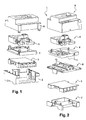
- an internal termination device of the state of the art may comprise, from the bottom up, a lower cover 2, a printed circuit 3 which performs the function of signal splitter or ADSL filter, the printed circuit 3 being covered by a cover 4, a connection and test module 5, and an upper cover 6 which covers the printed circuit 3, the cover 4 and the connection and test module 5.
- the top cover 6 is clipped on the lower cover 2.
- ADSL for "Asymmetric Digital Subscriber Line” in English (asymmetric digital link in French), refers to a digital communication technique.
- the role of ADSL filters is simple. They allow to separate the signal between the low frequencies used by conventional telephones and high frequencies dedicated to Internet browsing, the TV stream.
- the internal termination device thus makes it possible to check a possible fault on the line situated on the operator's side.
- the test socket of the indoor termination device shall provide continuity between the service line and the internal wiring of the housing.
- the insertion of a test plug must isolate the internal wiring of the connection line and allow to verify the presence of services on the connection side.
- RJ 45 which isolates the line of the subscriber, to test the local loop, and also allows the subscriber to test the presence of the tone. This action makes it possible to locate a possible fault on the operator's side.
- the RJ 45 plug is thus a line opening socket for the test which makes it possible to locate faults upstream of the internal termination device.
- the reference “RJ” comes from the English "Registered Jack”.
- the RJ 45 jack is a commonly used connector for Ethernet connections and includes eight electrical connection pins.
- the module 5 thus comprises a RJ 45 socket 7 designed to accommodate a male RJ 45 plug.
- the module 5 comprises an RC test module 8 comprising a resistor in series with a capacitance.
- the RC 8 module is used to perform the remote test.
- the module 5 may furthermore comprise a lightning protection module in order to protect the line, the equipment and the users against accidental overvoltages.
- connection and test module In case of failure of the connection and test module, such as for example a disconnection, a disturbance or a deterioration of the line, the maintenance is tricky because in this device of internal termination of the state of the art, the connection module and test is integrated and is inseparable from all. This implies an unconventional intervention to change the connection and test module and does not replace it by any desired connection and test module, in particular by a connection and test module compliant with the UTE C 93 standard. 431.
- the invention aims to remedy these drawbacks.
- the first module and the second module are separate and the second module is covered with rails adapted to be fixed on a support of the first module.
- the second module typically comprises a printed circuit.
- the printed circuit may be covered with a cover provided with said rails.
- the printed circuit may be arranged on a lower cover.
- the rails can be clipped into notches of the support of the first module.
- the device may comprise a test socket, typically an RJ 45 socket, capable of disconnecting the network from the subscriber's side by inserting a corresponding plug into the socket.
- a test socket typically an RJ 45 socket
- the first module may include a test module comprising a series resistor with a capacitance.
- the first module may include a lightning protection module.
- the first module can be covered by an upper cover.
- the inner termination device 1 comprises a specific additional piece, namely a base 9 which will cover the printed circuit 3.
- the base 9 is provided with two parallel rails 10 which will be clipped in. housing 11 (notches) of the cover 4.
- the cover 4 is the support of the module 5 connection and test.
- the base 9 provided with rails 10 constitutes a standard fastening area similar to a DIN rail (for "Deutsches Institut für Normung” in German).
- the base 9 can be fixed on the lower cover 2, for example by clipping.
- a standard interface is created between the printed circuit 3 providing the auxiliary functions (ADSL filter, splitter in the English language) and the connection and test module.
- This interface makes it possible, in case of failure of the connection and test module 5, to change the module 5 and replace it with any module 5 compliant with the UTE C 93-431 standard. It is thus only necessary to change the faulty module 5, the module 3 which provides the ADSL filter / signal divider function being retained.
- the Figures 3 and 4 are detailed views of the base 9.
- the rails 10 are advantageously each provided with a horizontal fin parallel to the base 9 and which facilitates the clipping of the rails 10 in the housing 11.
Landscapes
- Engineering & Computer Science (AREA)
- Signal Processing (AREA)
- Computer Networks & Wireless Communication (AREA)
- Structure Of Telephone Exchanges (AREA)
- Monitoring And Testing Of Exchanges (AREA)
Abstract
Description
- La présente invention a pour objet un dispositif de terminaison intérieur.
- Un dispositif de terminaison intérieur (appelé également DTI) est un boîtier implanté à l'entrée de l'installation d'un abonné. Il sépare et définit la démarcation entre la boucle locale d'un opérateur de télécommunication et le réseau intérieur de l'abonné. Il matérialise ainsi la limite de responsabilité entre les deux parties.
- La boucle locale est la partie de la ligne téléphonique (paires de cuivre) allant du répartiteur de l'opérateur jusqu'à la prise de l'abonné.
- Tel qu'illustré à la
figure 1 , un dispositif de terminaison intérieur de l'état de la technique peut comprendre, de bas en haut, un couvercle inférieur 2, un circuit imprimé 3 qui réalise la fonction de diviseur de signal ou de filtre ADSL, le circuit imprimé 3 étant recouvert par un couvercle 4, un module 5 de connexion et de test, et un couvercle supérieur 6 qui recouvre le circuit imprimé 3, le couvercle 4 et le module 5 de connexion et de test. Le couvercle supérieur 6 se clippe sur le couvercle inférieur 2. - ADSL, pour « Asymmetric Digital Subscriber Line » en langue anglaise (liaison numérique asymétrique en langue française), désigne une technique de communication numérique. Le rôle des filtres ADSL est simple. Ils permettent de séparer le signal entre les basses fréquences utilisées par les appareils téléphoniques classiques et les hautes fréquences consacrées à la navigation Internet, le flux TV.
- Le module 5 de connexion et de test est la pièce qui permet de connecter au moins une paire de conducteurs, typiquement en cuivre, d'un abonné à une paire de conducteurs d'un opérateur. Il peut par exemple permettre le raccordement par contacts auto-dénudant de :
- une paire en entrée
- trois paires en sortie abonné (désignées 1, 2 et test)
- Il permet également d'assurer une fonction de test. Le dispositif de terminaison intérieur permet ainsi de vérifier un éventuel défaut sur la ligne situé du côté de l'opérateur.
- La prise de test du dispositif de terminaison intérieur doit permettre la continuité entre la ligne de branchement et le câblage interne du logement. L'insertion d'une fiche de test doit isoler le câblage interne de la ligne de branchement et permettre de vérifier la présence des services côté branchement.
- Pour effectuer la vérification, il suffit de connecter une prise appelée RJ 45, ce qui isole la ligne de l'abonné, permet de tester la boucle locale, et permet aussi à l'abonné de tester la présence de la tonalité. Cette action permet de localiser un éventuel défaut du côté de l'opérateur. La prise RJ 45 est ainsi une prise d'ouverture de ligne pour le test qui permet de localiser des défauts en amont du dispositif de terminaison intérieur. La référence « RJ » vient de l'anglais « Registered Jack » (prise jack enregistrée). La prise RJ 45 est un connecteur utilisé couramment pour les connexions Ethernet et qui comprend huit broches de connexions électriques. Le module 5 comprend ainsi une prise RJ 45 femelle 7 destinée à accueillir une prise RJ 45 mâle.
- Le module 5 comprend un module d'essai RC 8 comprenant une résistance en série avec une capacité. Le module RC 8 permet d'effectuer le test à distance. Le module 5 peut comprendre en outre un module de protection parafoudre afin de protéger la ligne, les équipements et les utilisateurs contre les surtensions accidentelles.
- Lors d'une intervention de maintenance, en cas de défaillance du module de connexion et de test, comme par exemple une déconnexion, une perturbation ou encore une détérioration de la ligne, la maintenance est délicate car dans ce dispositif de terminaison intérieur de l'état de la technique, le module de connexion et de test est intégré et est indissociable de l'ensemble. Ceci implique une intervention non conventionnelle pour changer le module de connexion et de test et ne permet pas de le remplacer par tout module de connexion et de test souhaitable, en particulier par un module de connexion et de test conforme à la norme UTE C 93-431.
- L'invention vise à remédier à ces inconvénients.
- L'invention a ainsi pour objet un dispositif de terminaison intérieur, comprenant :
- un premier module assurant une fonction de connexion d'une paire de conducteurs d'un abonné à une paire de conducteurs d'un opérateur de télécommunication et une fonction de test permettant de localiser un défaut sur la ligne téléphonique de l'abonné, et
- un deuxième module assurant une fonction de filtre ADSL ou une fonction de division de signal,
- Dans le dispositif selon l'invention, le premier module et le deuxième module sont distincts et le deuxième module est recouvert de rails aptes à se fixer sur un support du premier module.
- On peut ainsi facilement dissocier les deux modules et remplacer le premier module en cas de défaillance de celui-ci.
- Le deuxième module comprend typiquement un circuit imprimé.
- Le circuit imprimé peut être recouvert d'un couvercle muni desdits rails.
- Le circuit imprimé peut être disposé sur un couvercle inférieur.
- Les rails peuvent être clippés dans des encoches du support du premier module.
- Le dispositif peut comprendre une prise femelle de test, typiquement une prise femelle RJ 45, apte à déconnecter le réseau du côté de l'abonné par insertion d'une prise mâle correspondante dans la prise femelle.
- Le premier module peut comprendre un module de test comprenant une résistance en série avec une capacité.
- Le premier module peut comprendre un module de protection parafoudre.
- Le premier module peut être recouvert par un couvercle supérieur.
- D'autres buts, caractéristiques et avantages de l'invention apparaîtront à la lecture de la description suivante, donnée uniquement à titre d'exemple non limitatif, et faite en référence aux dessins annexés, sur lesquels :
- la
figure 1 , déjà décrite, est une vue en perspective éclatée d'un dispositif de terminaison intérieur de l'état de la technique, - la
figure 2 est une vue en perspective éclatée d'un dispositif de terminaison intérieur selon l'invention, - les
figures 3 et 4 sont des vues de détail du dispositif selon l'invention, et - la
figure 5 est une vue en perspective du dispositif selon l'invention. - Tel qu'illustré à la
figure 2 , sur laquelle les éléments identiques à ceux de lafigure 1 portent les mêmes références, le dispositif de terminaison intérieur 1 selon l'invention comprend une pièce supplémentaire spécifique, à savoir une embase 9 qui va recouvrir le circuit imprimé 3. L'embase 9 est munie de deux rails parallèles 10 qui vont se clipper dans des logements 11 (des encoches) du couvercle 4. Le couvercle 4 constitue le support du module 5 de connexion et de test. L'embase 9 munie des rails 10 constitue une zone de fixation standard similaire à un rail DIN (pour « Deutsches Institut für Normung » en langue allemande). L'embase 9 peut être fixée sur le couvercle inférieur 2, par exemple par clippage. - Ainsi, on crée une interface standard entre le circuit imprimé 3 assurant les fonctions auxiliaires (filtre ADSL, diviseur de signal (« splitter » en langue anglaise)) et le module 5 de connexion et de test. Cette interface permet en cas de défaillance du module 5 de connexion et de test de changer le module 5 et de le remplacer par tout module 5 conforme à la norme UTE C 93-431. On n'a ainsi besoin que de changer le module 5 défaillant, le module 3 qui assure la fonction de filtre ADSL/diviseur de signal étant conservé.
- Les
figures 3 et 4 sont des vues de détail de l'embase 9. Les rails 10 sont avantageusement munis chacun d'une ailette horizontale parallèle à l'embase 9 et qui facilite le clippage des rails 10 dans les logements 11.
Claims (9)
- Dispositif de terminaison intérieur (1), comprenant :- un premier module (5) assurant une fonction de connexion d'une paire de conducteurs d'un abonné à une paire de conducteurs d'un opérateur de télécommunication et une fonction de test permettant de localiser un défaut sur la ligne téléphonique de l'abonné, et- un deuxième module (3) assurant une fonction de filtre ADSL ou une fonction de division de signal,le dispositif (1) étant caractérisé en ce que le premier module (5) et le deuxième module (3) sont distincts et en ce que le deuxième module (3) est recouvert de rails (10) aptes à se fixer sur un support (4) du premier module (5).
- Dispositif (1) selon la revendication 1, caractérisé en ce que le deuxième module (3) comprend un circuit imprimé.
- Dispositif (1) selon la revendication 2, caractérisé en ce que le circuit imprimé (3) est recouvert d'un couvercle (9) muni desdits rails (10).
- Dispositif (1) selon la revendication 2 ou 3, caractérisé en ce que le circuit imprimé (3) est disposé sur un couvercle inférieur (2).
- Dispositif (1) selon l'une des revendications 1 à 4, caractérisé en ce que les rails (10) sont clippés dans des encoches (11) du support (4) du premier module (5).
- Dispositif (1) selon l'une des revendications 1 à 5, caractérisé en ce qu'il comprend une prise femelle de test (7) apte à déconnecter le réseau du côté de l'abonné par insertion d'une prise mâle correspondante dans la prise femelle (7).
- Dispositif (1) selon l'une des revendications 1 à 6, caractérisé en ce que le premier module (5) comprend un module de test (8) comprenant une résistance en série avec une capacité.
- Dispositif (1) selon l'une des revendications 1 à 7, caractérisé en ce que le premier module (5) comprend un module de protection parafoudre.
- Dispositif (1) selon l'une des revendications 1 à 8, caractérisé en ce que le premier module (5) est recouvert par un couvercle supérieur (6).
Applications Claiming Priority (1)
| Application Number | Priority Date | Filing Date | Title |
|---|---|---|---|
| FR1458401A FR3025682B1 (fr) | 2014-09-08 | 2014-09-08 | Dispositif de terminaison interieur |
Publications (2)
| Publication Number | Publication Date |
|---|---|
| EP2993881A1 true EP2993881A1 (fr) | 2016-03-09 |
| EP2993881B1 EP2993881B1 (fr) | 2017-08-16 |
Family
ID=52016759
Family Applications (1)
| Application Number | Title | Priority Date | Filing Date |
|---|---|---|---|
| EP15184241.6A Active EP2993881B1 (fr) | 2014-09-08 | 2015-09-08 | Dispositif de terminaison interieur |
Country Status (2)
| Country | Link |
|---|---|
| EP (1) | EP2993881B1 (fr) |
| FR (1) | FR3025682B1 (fr) |
Citations (5)
| Publication number | Priority date | Publication date | Assignee | Title |
|---|---|---|---|---|
| EP0966147A2 (fr) * | 1998-05-28 | 1999-12-22 | Siecor Operations, LLC | Dispositif séparateur DSL pour l'utilisation à l'intérieur |
| US6026160A (en) * | 1997-12-31 | 2000-02-15 | Siecor Operations, Llc | xDSL splitter interconnect module for network interface device |
| WO2009131675A1 (fr) * | 2008-04-22 | 2009-10-29 | Afl Telecommunications, Llc | Interface de démarcation xdsl universelle avec capacité multifonctionnelle et amélioration d’efficacité de signal |
| US20090314907A1 (en) * | 2008-06-23 | 2009-12-24 | Romerein Robert L | Methods and apparatus for mounting devices |
| US20110128708A1 (en) * | 2009-11-30 | 2011-06-02 | Blake Kathleen E | Coax-balun module |
-
2014
- 2014-09-08 FR FR1458401A patent/FR3025682B1/fr active Active
-
2015
- 2015-09-08 EP EP15184241.6A patent/EP2993881B1/fr active Active
Patent Citations (5)
| Publication number | Priority date | Publication date | Assignee | Title |
|---|---|---|---|---|
| US6026160A (en) * | 1997-12-31 | 2000-02-15 | Siecor Operations, Llc | xDSL splitter interconnect module for network interface device |
| EP0966147A2 (fr) * | 1998-05-28 | 1999-12-22 | Siecor Operations, LLC | Dispositif séparateur DSL pour l'utilisation à l'intérieur |
| WO2009131675A1 (fr) * | 2008-04-22 | 2009-10-29 | Afl Telecommunications, Llc | Interface de démarcation xdsl universelle avec capacité multifonctionnelle et amélioration d’efficacité de signal |
| US20090314907A1 (en) * | 2008-06-23 | 2009-12-24 | Romerein Robert L | Methods and apparatus for mounting devices |
| US20110128708A1 (en) * | 2009-11-30 | 2011-06-02 | Blake Kathleen E | Coax-balun module |
Also Published As
| Publication number | Publication date |
|---|---|
| FR3025682B1 (fr) | 2018-03-30 |
| EP2993881B1 (fr) | 2017-08-16 |
| FR3025682A1 (fr) | 2016-03-11 |
Similar Documents
| Publication | Publication Date | Title |
|---|---|---|
| US6026160A (en) | xDSL splitter interconnect module for network interface device | |
| US20130089128A1 (en) | Digital subscriber line (dsl) access multiplexer wiring validation | |
| EP1175078A2 (fr) | Système et méthode pour fournir des données et des services de voix sur une ligne partagée | |
| US8259906B2 (en) | System and method for testing a DSL and POTS connection | |
| JP2000502207A (ja) | 電気コネクタモジュール用ワイヤキャリア | |
| WO2014065843A2 (fr) | Connexion rapide de multiples interfaces à l'aide de câbles et de connecteurs multibroches pour prendre en charge un test à grand volume de dispositifs à l'aide d'une pluralité d'interfaces | |
| US20100316101A1 (en) | Cross connect block | |
| US10283918B2 (en) | Electrical terminal block | |
| US6039578A (en) | Network interface device for line testing | |
| JPH11317968A (ja) | ネットワ―クインタフェ―スデバイス用xDSLスプリッタラインモジュ―ル | |
| EP2993881B1 (fr) | Dispositif de terminaison interieur | |
| US9312652B2 (en) | Switchable modular jack assembly for telecommunications systems | |
| WO2017220913A1 (fr) | Mesure et diagnostic de bruit externe pour système de transmission sur ligne électrique bifilaire | |
| CN106662609B (zh) | 用于定位故障的方法 | |
| US6418195B1 (en) | Apparatus for communicating a diagnostic device with a telecommunications system through a remote network unit | |
| MXPA06011640A (es) | Modulo de telecomunicaciones y montaje que incluye al menos un modulo de telecomunicaciones. | |
| US10770890B2 (en) | Modular access connection system | |
| JP2007505593A (ja) | ネットワーク接続検出組立体 | |
| FR2896935A1 (fr) | Dispositif de connexion electrique d'une ligne telephonique analogique bifilaire et desserte interne associee. | |
| FR2716324A1 (fr) | Dispositif de brassage de câbles multibrins, notamment pour applications téléphoniques. | |
| US7499526B2 (en) | Termination module including subscriber bridge having burglar alarm connections | |
| EP2487492B1 (fr) | Procédé de test électrique d'un réseau de paires de conducteurs | |
| CA2432604C (fr) | Module de securite et de communications | |
| EP1632084A2 (fr) | Dispositif adaptateur d'impedance du canal de transmission haut-debit d'une installation terminale cuivre | |
| US8085928B2 (en) | Isolating an inactive cable pair from a bridged active cable pair |
Legal Events
| Date | Code | Title | Description |
|---|---|---|---|
| PUAI | Public reference made under article 153(3) epc to a published international application that has entered the european phase |
Free format text: ORIGINAL CODE: 0009012 |
|
| AK | Designated contracting states |
Kind code of ref document: A1 Designated state(s): AL AT BE BG CH CY CZ DE DK EE ES FI FR GB GR HR HU IE IS IT LI LT LU LV MC MK MT NL NO PL PT RO RS SE SI SK SM TR |
|
| AX | Request for extension of the european patent |
Extension state: BA ME |
|
| 17P | Request for examination filed |
Effective date: 20160909 |
|
| RBV | Designated contracting states (corrected) |
Designated state(s): AL AT BE BG CH CY CZ DE DK EE ES FI FR GB GR HR HU IE IS IT LI LT LU LV MC MK MT NL NO PL PT RO RS SE SI SK SM TR |
|
| GRAP | Despatch of communication of intention to grant a patent |
Free format text: ORIGINAL CODE: EPIDOSNIGR1 |
|
| INTG | Intention to grant announced |
Effective date: 20170313 |
|
| GRAS | Grant fee paid |
Free format text: ORIGINAL CODE: EPIDOSNIGR3 |
|
| GRAA | (expected) grant |
Free format text: ORIGINAL CODE: 0009210 |
|
| RAP1 | Party data changed (applicant data changed or rights of an application transferred) |
Owner name: NEXANS |
|
| AK | Designated contracting states |
Kind code of ref document: B1 Designated state(s): AL AT BE BG CH CY CZ DE DK EE ES FI FR GB GR HR HU IE IS IT LI LT LU LV MC MK MT NL NO PL PT RO RS SE SI SK SM TR |
|
| REG | Reference to a national code |
Ref country code: GB Ref legal event code: FG4D Free format text: NOT ENGLISH |
|
| REG | Reference to a national code |
Ref country code: CH Ref legal event code: EP |
|
| REG | Reference to a national code |
Ref country code: IE Ref legal event code: FG4D Free format text: LANGUAGE OF EP DOCUMENT: FRENCH |
|
| REG | Reference to a national code |
Ref country code: AT Ref legal event code: REF Ref document number: 920127 Country of ref document: AT Kind code of ref document: T Effective date: 20170915 |
|
| REG | Reference to a national code |
Ref country code: DE Ref legal event code: R096 Ref document number: 602015004123 Country of ref document: DE Ref country code: FR Ref legal event code: PLFP Year of fee payment: 3 |
|
| REG | Reference to a national code |
Ref country code: NL Ref legal event code: MP Effective date: 20170816 |
|
| REG | Reference to a national code |
Ref country code: LT Ref legal event code: MG4D |
|
| REG | Reference to a national code |
Ref country code: AT Ref legal event code: MK05 Ref document number: 920127 Country of ref document: AT Kind code of ref document: T Effective date: 20170816 |
|
| PG25 | Lapsed in a contracting state [announced via postgrant information from national office to epo] |
Ref country code: AT Free format text: LAPSE BECAUSE OF FAILURE TO SUBMIT A TRANSLATION OF THE DESCRIPTION OR TO PAY THE FEE WITHIN THE PRESCRIBED TIME-LIMIT Effective date: 20170816 Ref country code: NL Free format text: LAPSE BECAUSE OF FAILURE TO SUBMIT A TRANSLATION OF THE DESCRIPTION OR TO PAY THE FEE WITHIN THE PRESCRIBED TIME-LIMIT Effective date: 20170816 Ref country code: LT Free format text: LAPSE BECAUSE OF FAILURE TO SUBMIT A TRANSLATION OF THE DESCRIPTION OR TO PAY THE FEE WITHIN THE PRESCRIBED TIME-LIMIT Effective date: 20170816 Ref country code: FI Free format text: LAPSE BECAUSE OF FAILURE TO SUBMIT A TRANSLATION OF THE DESCRIPTION OR TO PAY THE FEE WITHIN THE PRESCRIBED TIME-LIMIT Effective date: 20170816 Ref country code: SE Free format text: LAPSE BECAUSE OF FAILURE TO SUBMIT A TRANSLATION OF THE DESCRIPTION OR TO PAY THE FEE WITHIN THE PRESCRIBED TIME-LIMIT Effective date: 20170816 Ref country code: NO Free format text: LAPSE BECAUSE OF FAILURE TO SUBMIT A TRANSLATION OF THE DESCRIPTION OR TO PAY THE FEE WITHIN THE PRESCRIBED TIME-LIMIT Effective date: 20171116 |
|
| PG25 | Lapsed in a contracting state [announced via postgrant information from national office to epo] |
Ref country code: LV Free format text: LAPSE BECAUSE OF FAILURE TO SUBMIT A TRANSLATION OF THE DESCRIPTION OR TO PAY THE FEE WITHIN THE PRESCRIBED TIME-LIMIT Effective date: 20170816 Ref country code: PL Free format text: LAPSE BECAUSE OF FAILURE TO SUBMIT A TRANSLATION OF THE DESCRIPTION OR TO PAY THE FEE WITHIN THE PRESCRIBED TIME-LIMIT Effective date: 20170816 Ref country code: BG Free format text: LAPSE BECAUSE OF FAILURE TO SUBMIT A TRANSLATION OF THE DESCRIPTION OR TO PAY THE FEE WITHIN THE PRESCRIBED TIME-LIMIT Effective date: 20171116 Ref country code: RS Free format text: LAPSE BECAUSE OF FAILURE TO SUBMIT A TRANSLATION OF THE DESCRIPTION OR TO PAY THE FEE WITHIN THE PRESCRIBED TIME-LIMIT Effective date: 20170816 Ref country code: IS Free format text: LAPSE BECAUSE OF FAILURE TO SUBMIT A TRANSLATION OF THE DESCRIPTION OR TO PAY THE FEE WITHIN THE PRESCRIBED TIME-LIMIT Effective date: 20171216 Ref country code: ES Free format text: LAPSE BECAUSE OF FAILURE TO SUBMIT A TRANSLATION OF THE DESCRIPTION OR TO PAY THE FEE WITHIN THE PRESCRIBED TIME-LIMIT Effective date: 20170816 Ref country code: GR Free format text: LAPSE BECAUSE OF FAILURE TO SUBMIT A TRANSLATION OF THE DESCRIPTION OR TO PAY THE FEE WITHIN THE PRESCRIBED TIME-LIMIT Effective date: 20171117 |
|
| REG | Reference to a national code |
Ref country code: DE Ref legal event code: R119 Ref document number: 602015004123 Country of ref document: DE |
|
| PG25 | Lapsed in a contracting state [announced via postgrant information from national office to epo] |
Ref country code: CZ Free format text: LAPSE BECAUSE OF FAILURE TO SUBMIT A TRANSLATION OF THE DESCRIPTION OR TO PAY THE FEE WITHIN THE PRESCRIBED TIME-LIMIT Effective date: 20170816 Ref country code: RO Free format text: LAPSE BECAUSE OF FAILURE TO SUBMIT A TRANSLATION OF THE DESCRIPTION OR TO PAY THE FEE WITHIN THE PRESCRIBED TIME-LIMIT Effective date: 20170816 Ref country code: DK Free format text: LAPSE BECAUSE OF FAILURE TO SUBMIT A TRANSLATION OF THE DESCRIPTION OR TO PAY THE FEE WITHIN THE PRESCRIBED TIME-LIMIT Effective date: 20170816 |
|
| PG25 | Lapsed in a contracting state [announced via postgrant information from national office to epo] |
Ref country code: EE Free format text: LAPSE BECAUSE OF FAILURE TO SUBMIT A TRANSLATION OF THE DESCRIPTION OR TO PAY THE FEE WITHIN THE PRESCRIBED TIME-LIMIT Effective date: 20170816 Ref country code: SM Free format text: LAPSE BECAUSE OF FAILURE TO SUBMIT A TRANSLATION OF THE DESCRIPTION OR TO PAY THE FEE WITHIN THE PRESCRIBED TIME-LIMIT Effective date: 20170816 Ref country code: MC Free format text: LAPSE BECAUSE OF FAILURE TO SUBMIT A TRANSLATION OF THE DESCRIPTION OR TO PAY THE FEE WITHIN THE PRESCRIBED TIME-LIMIT Effective date: 20170816 Ref country code: IT Free format text: LAPSE BECAUSE OF FAILURE TO SUBMIT A TRANSLATION OF THE DESCRIPTION OR TO PAY THE FEE WITHIN THE PRESCRIBED TIME-LIMIT Effective date: 20170816 Ref country code: SK Free format text: LAPSE BECAUSE OF FAILURE TO SUBMIT A TRANSLATION OF THE DESCRIPTION OR TO PAY THE FEE WITHIN THE PRESCRIBED TIME-LIMIT Effective date: 20170816 |
|
| PLBE | No opposition filed within time limit |
Free format text: ORIGINAL CODE: 0009261 |
|
| STAA | Information on the status of an ep patent application or granted ep patent |
Free format text: STATUS: NO OPPOSITION FILED WITHIN TIME LIMIT |
|
| REG | Reference to a national code |
Ref country code: IE Ref legal event code: MM4A |
|
| REG | Reference to a national code |
Ref country code: BE Ref legal event code: MM Effective date: 20170930 |
|
| PG25 | Lapsed in a contracting state [announced via postgrant information from national office to epo] |
Ref country code: LU Free format text: LAPSE BECAUSE OF NON-PAYMENT OF DUE FEES Effective date: 20170908 |
|
| 26N | No opposition filed |
Effective date: 20180517 |
|
| PG25 | Lapsed in a contracting state [announced via postgrant information from national office to epo] |
Ref country code: IE Free format text: LAPSE BECAUSE OF NON-PAYMENT OF DUE FEES Effective date: 20170908 Ref country code: DE Free format text: LAPSE BECAUSE OF NON-PAYMENT OF DUE FEES Effective date: 20180404 |
|
| PG25 | Lapsed in a contracting state [announced via postgrant information from national office to epo] |
Ref country code: BE Free format text: LAPSE BECAUSE OF NON-PAYMENT OF DUE FEES Effective date: 20170930 Ref country code: SI Free format text: LAPSE BECAUSE OF FAILURE TO SUBMIT A TRANSLATION OF THE DESCRIPTION OR TO PAY THE FEE WITHIN THE PRESCRIBED TIME-LIMIT Effective date: 20170816 |
|
| REG | Reference to a national code |
Ref country code: FR Ref legal event code: PLFP Year of fee payment: 4 |
|
| PG25 | Lapsed in a contracting state [announced via postgrant information from national office to epo] |
Ref country code: MT Free format text: LAPSE BECAUSE OF FAILURE TO SUBMIT A TRANSLATION OF THE DESCRIPTION OR TO PAY THE FEE WITHIN THE PRESCRIBED TIME-LIMIT Effective date: 20170816 |
|
| REG | Reference to a national code |
Ref country code: CH Ref legal event code: PL |
|
| PG25 | Lapsed in a contracting state [announced via postgrant information from national office to epo] |
Ref country code: HU Free format text: LAPSE BECAUSE OF FAILURE TO SUBMIT A TRANSLATION OF THE DESCRIPTION OR TO PAY THE FEE WITHIN THE PRESCRIBED TIME-LIMIT; INVALID AB INITIO Effective date: 20150908 |
|
| PG25 | Lapsed in a contracting state [announced via postgrant information from national office to epo] |
Ref country code: CH Free format text: LAPSE BECAUSE OF NON-PAYMENT OF DUE FEES Effective date: 20180930 Ref country code: LI Free format text: LAPSE BECAUSE OF NON-PAYMENT OF DUE FEES Effective date: 20180930 |
|
| PG25 | Lapsed in a contracting state [announced via postgrant information from national office to epo] |
Ref country code: CY Free format text: LAPSE BECAUSE OF FAILURE TO SUBMIT A TRANSLATION OF THE DESCRIPTION OR TO PAY THE FEE WITHIN THE PRESCRIBED TIME-LIMIT Effective date: 20170816 |
|
| PG25 | Lapsed in a contracting state [announced via postgrant information from national office to epo] |
Ref country code: MK Free format text: LAPSE BECAUSE OF FAILURE TO SUBMIT A TRANSLATION OF THE DESCRIPTION OR TO PAY THE FEE WITHIN THE PRESCRIBED TIME-LIMIT Effective date: 20170816 |
|
| PG25 | Lapsed in a contracting state [announced via postgrant information from national office to epo] |
Ref country code: TR Free format text: LAPSE BECAUSE OF FAILURE TO SUBMIT A TRANSLATION OF THE DESCRIPTION OR TO PAY THE FEE WITHIN THE PRESCRIBED TIME-LIMIT Effective date: 20170816 |
|
| PG25 | Lapsed in a contracting state [announced via postgrant information from national office to epo] |
Ref country code: PT Free format text: LAPSE BECAUSE OF FAILURE TO SUBMIT A TRANSLATION OF THE DESCRIPTION OR TO PAY THE FEE WITHIN THE PRESCRIBED TIME-LIMIT Effective date: 20170816 |
|
| PG25 | Lapsed in a contracting state [announced via postgrant information from national office to epo] |
Ref country code: HR Free format text: LAPSE BECAUSE OF FAILURE TO SUBMIT A TRANSLATION OF THE DESCRIPTION OR TO PAY THE FEE WITHIN THE PRESCRIBED TIME-LIMIT Effective date: 20170816 |
|
| PG25 | Lapsed in a contracting state [announced via postgrant information from national office to epo] |
Ref country code: AL Free format text: LAPSE BECAUSE OF FAILURE TO SUBMIT A TRANSLATION OF THE DESCRIPTION OR TO PAY THE FEE WITHIN THE PRESCRIBED TIME-LIMIT Effective date: 20170816 |
|
| GBPC | Gb: european patent ceased through non-payment of renewal fee |
Effective date: 20190908 |
|
| PG25 | Lapsed in a contracting state [announced via postgrant information from national office to epo] |
Ref country code: GB Free format text: LAPSE BECAUSE OF NON-PAYMENT OF DUE FEES Effective date: 20190908 |
|
| PGFP | Annual fee paid to national office [announced via postgrant information from national office to epo] |
Ref country code: FR Payment date: 20250922 Year of fee payment: 11 |