EP2993768A1 - Method for inserting magnet into rotor core - Google Patents
Method for inserting magnet into rotor core Download PDFInfo
- Publication number
- EP2993768A1 EP2993768A1 EP14792072.2A EP14792072A EP2993768A1 EP 2993768 A1 EP2993768 A1 EP 2993768A1 EP 14792072 A EP14792072 A EP 14792072A EP 2993768 A1 EP2993768 A1 EP 2993768A1
- Authority
- EP
- European Patent Office
- Prior art keywords
- magnet
- assembly
- rotor core
- insertion hole
- members
- Prior art date
- Legal status (The legal status is an assumption and is not a legal conclusion. Google has not performed a legal analysis and makes no representation as to the accuracy of the status listed.)
- Granted
Links
Images



Classifications
-
- H—ELECTRICITY
- H02—GENERATION; CONVERSION OR DISTRIBUTION OF ELECTRIC POWER
- H02K—DYNAMO-ELECTRIC MACHINES
- H02K15/00—Processes or apparatus specially adapted for manufacturing, assembling, maintaining or repairing of dynamo-electric machines
- H02K15/02—Processes or apparatus specially adapted for manufacturing, assembling, maintaining or repairing of dynamo-electric machines of stator or rotor bodies
- H02K15/03—Processes or apparatus specially adapted for manufacturing, assembling, maintaining or repairing of dynamo-electric machines of stator or rotor bodies having permanent magnets
Definitions
- the present invention relates to a technique of inserting a magnet into a rotor core of an electric motor.
- PM motors Permanent magnet type synchronous motors, in which permanent magnets are embedded in rotors (hereinafter referred to as "PM motors"), are well known as electric motors used in electric vehicles and the like. Further, methods of reducing eddy current loss by dividing the magnets to be embedded are well known as methods of improving efficiency of the PM motors. According to WO2001/095460 , for example, magnet pieces that are divided into a plurality of pieces are adhered to each other to form one long plate-shaped magnet, and this long plate-shaped magnet is inserted into a magnet insertion hole in a rotor core.
- the magnet pieces are adhered to each other by aligning the magnet pieces in an outer frame that is formed by organic resin, and applying pressure and heat and the like from the outside, so as to form the long plate-shaped magnet. This results in high manufacturing costs required for forming the long plate-shaped magnet.
- the magnet pieces when the magnet pieces are separately inserted into the magnet insertion hole in the rotor core in order to reduce the costs required for forming the long plate-shaped magnet, the magnet pieces get easily stuck in the middle of the magnet insertion hole and do not reach the bottom of the insertion hole, in the case where corners of the magnet pieces are not subjected to chamfering.
- the corners of all the magnet pieces to be inserted are subjected to the chamfering, cost of the chamfering increases greatly, and performance of the magnet deteriorates due to a reduction in magnet volume by the chamfering.
- the present invention is made in view of the above-described problems, and an object of the present invention is to provide a method of inserting magnet pieces into a magnet insertion hole, while suppressing increase in costs and deterioration of performance.
- a magnet insertion method into a rotor core for inserting an assembly into a magnet insertion hole provided in the rotor core of an electric motor, the assembly being formed by laminating a plurality of members, including at least a plurality of magnet pieces, in a line
- the magnet insertion method comprising; forming the assembly by arranging a front member, having a surface surrounded by a chamfered ridge line, to cause the surface to be a front side end surface upon insertion, by laminating, on a rear side of the front member in an insertion direction, other members, without having the chamfered ridge line, in a line along the insertion direction to cause the other members to be hidden inside a projection of the front member when being projected from an insertion hole side, and by temporarily holding the front member and the other members.
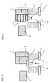
- Fig. 1 is a schematic block diagram of a magnet insertion device, to which a first embodiment is applied;
- Fig. 1 is a schematic block diagram of a magnet insertion device 1 that is used in a first embodiment.
- the magnet insertion device 1 is a device for inserting an assembly 2 that is formed by laminating a plurality of magnet pieces 3 as a tip member or another member into a magnet insertion hole 6 in a rotor core 4 that is formed by laminated steel sheets.
- the assembly 2 will be described in detail later.
- the magnet insertion device 1 is provided with a rotor core support disk 5 that holds the rotor core 4, a magnet receiver 9 that holds the assembly 2 and serves as an assembly receiving member, an alignment jig 7 that holds side surfaces of the assembly 2, and a magnet alignment rod 10 that presses the assembly 2 against the alignment jig 7.
- the magnet receiver 9, driven by a magnet receiver drive unit 13, moves along an axis of the magnet insertion hole 6 from the lower side to the upper side of the magnet insertion hole 6.
- the magnet receiver drive unit 13 is supposed to be a unit that does not produce vibration, such as an air cylinder.
- the alignment jig 7 has a surface that faces against the side surface on the right side of the assembly 2 in the drawing, and a surface that faces against the side surface on the back side of the assembly 2 in the drawing.
- the magnet alignment rod 10 and the alignment rod drive unit 12 as illustrated in Fig. 1 ones that move from the front side to the back side in the drawing are also provided.
- the rotor core support disk 5 has an opening 5A at a position corresponding to the magnet insertion hole 6 in the rotor core 4, the opening 5A being smaller than the cross section of the assembly 2 crossing the axis of the magnet insertion hole 6, as will be described later.
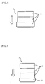
- Fig. 2 and Fig. 3 are views for explaining the assembly 2. Arrows in the drawings indicate the direction of movement when the assembly 2 is inserted into the magnet insertion hole 6 (hereinafter referred to as the insertion direction).
- the assembly 2 is formed by laminating the magnet pieces 3, divided into a plurality of pieces, in a line along the insertion direction.
- the magnet piece 3, to be the front piece upon insertion has its surface surrounded by a chamfered ridge line, and is arranged in such a manner that the surface surrounded by the chamfered ridge line becomes the front side end surface upon insertion.
- the second and the third magnet pieces 3 from the insertion direction do not have the chamfered ridge line.
- the second and the third magnet pieces 3 from the insertion direction are arranged in such a manner that, when the assembly 2 is projected from the insertion direction, the second and the third magnet pieces 3 are hidden inside the projection of the front magnet piece 3.
- the projections of all the magnet pieces 3 included in the assembly 2 have the same shape when being projected from the side of the magnet insertion hole 6.
- the magnet receiver 9 is located at a position lower than the rotor core support disk 5, and the magnet alignment rods 10 and the alignment jig 7 are located outward in a radial direction of the magnet insertion hole 6.
- the rotor core 4 is arranged on the rotor core support disk 5, and the magnet receiver 9 is ascended to a position higher than the upper end surface of the rotor core 4.
- the magnet pieces 3 are laminated on the ascended magnet receiver 9 in the same order as that of Fig. 3 .
- the magnet pieces 3 are supplied in order by a not-illustrated supply device, such as a robot arm, for example.
- a not-illustrated supply device such as a robot arm, for example.
- the alignment jig 7 is moved so that the surfaces of the alignment jig 7 abutting against the magnet pieces 3 (hereinafter referred to as magnet piece reference surfaces 8), in the right/left direction and the front/back direction in the drawing, are lined up with the wall of the magnet insertion hole 6.
- the magnet piece reference surfaces 8 may be closer to the center of the magnet insertion hole 6 by about 0.01 mm than the wall of the magnet insertion hole 6.
- the alignment jig 7 and the magnet alignment rods 10 may have such shape and arrangement that are able to prevent the magnet piece 3 from dropping from the magnet receiver 9 or from the lower magnet piece 3, so as to avoid a fall of the laminated magnet pieces 3.
- the magnet alignment rods 10 are pressed against the magnet pieces 3, as illustrated in Fig. 6 , so as to align the laminated magnet pieces 3 along the magnet piece reference surfaces 8. Thereby, the second and the third magnet pieces 3 from the bottom are hidden inside the front magnet piece 3, when being projected from the side of the magnet insertion hole 6. When interference between the magnet alignment rods 10 occurs, one of the magnet alignment rods 10 is retracted.
- the magnet piece reference surfaces 8 are also suitable to cause the magnet piece reference surfaces 8 to line up with the wall of the magnet insertion hole 6 and to move the magnet alignment rods 10, before laminating the magnet pieces 3, so that the alignment is finished when the lamination is finished.
- the magnet receiver 9 is descended to a position lower than the lower end of the rotor core 4.
- the assembly 2 remains inside the magnet insertion hole 6 as it is get stuck over the opening 5A of the rotor core support disk 5, and the insertion of the magnet pieces 3 into the magnet insertion hole 6 is thus finished.
- the tip surface is chamfered and the plurality of magnet pieces 3 are aligned in such a manner that the second and the third magnet pieces 3 are hidden inside the front magnet piece 3, when being projected from the side of the magnet insertion hole 6, as described above. Supposing that the assembly 2 comes in contact with the wall of the magnet insertion hole 6, at the time of descending the magnet receiver 9, the surface that comes in contact with the wall is the chamfered front side end surface. Thus, the assembly 2 reaches the lower end of the magnet insertion hole 6, without being stuck in the middle. As it is not necessary to chamfer the second and the third magnet pieces 3 from the bottom, the costs required for the chamfering can be reduced.
- Fig. 8 is a view illustrating another example of the assembly 2, to which this embodiment can be applied.
- the difference from the assembly 2 of Fig. 3 is that, when being projected from the side of the magnet insertion hole 6, the projection of the front magnet piece 3 is larger than the projections of the second and the third magnet pieces 3 from the bottom, and that a difference in level is formed between the front magnet piece 3 and the magnet piece 3 second from the bottom. It is also possible to insert the assembly 2 like this into the magnet insertion hole 6 by the above-described process. Incidentally, when using the assembly 2 of Fig.
- each of the magnet alignment rods 10 and the alignment jig 7, at the position abutting against the magnet pieces 3, be formed to have a shape corresponding to the difference in level formed between the front magnet piece 3 and the magnet piece 3 second from the bottom.
- the alignment jig 7 it is preferable to form the alignment jig 7 to have flat surfaces, and each of the magnet alignment rods 10 to have such a shape that corresponds to the difference in level formed on the side surface of the magnet alignment rod 10 of the assembly 2 when the plurality of magnet pieces 3 are abutted against the alignment jig 7.
- the front magnet piece 3 having the surface surrounded by the chamfered ridge line, is arranged to be the front side end surface upon insertion and, on the back side thereof along the insertion direction, other magnet pieces 3, without having the chamfered ridge line, are laminated. Further, the plurality of magnet pieces 3 are aligned in a line along the insertion direction so that, when being projected from the side of the insertion hole, the other magnet pieces 3 are hidden inside the projection of the front magnet piece 3. Then, the plurality of magnet pieces 3 are held temporarily, while being aligned as described above, and thus the assembly 2 is formed.
- the term "held temporarily” means the state where the plurality of magnet pieces 3 are laminated on the magnet receiver 9, without being adhered to each other by an adhesive, nor being formed integrally by resin molding or the like.
- edge portions of the magnet pieces 3 that are not chamfered are not exposed when viewed from the side of the magnet insertion hole 6, and the chamfered portion, provided on the front magnet piece 3, serves as a guide.
- the assembly 2 is inserted to the lower end of the magnet insertion hole 6, without being stuck in the middle against the inner wall of the magnet insertion hole 6.
- the chamfering processing is applied to the front magnet piece 3 only, it is possible to suppress reduction in the volume of the magnet by the chamfering processing, and to avoid deterioration of performance of the magnet. In addition, it is possible to reduce the costs required for the chamfering processing.
- the rotor core 4 is arranged in such a manner that the axis of the magnet insertion hole 6 extends in the vertical direction, and the alignment jig 7 that holds at least two side surfaces of the assembly 2, the side surfaces being perpendicular to each other, and the magnet receiver 9 that holds the front side end surface of the assembly 2 upon insertion are arranged at a position higher than the magnet insertion hole 6.
- the plurality of magnet pieces 3 are laminated on the magnet receiver 9 and aligned by being pressed by the magnet alignment rods 10 from directions opposing the alignment jig 7, so as to form the assembly 2. Thus, the alignment of the magnet pieces 3 can be made accurately.
- the assembly 2 is not stuck against the wall of the magnet insertion hole 6, as described above. Therefore, even though the magnet pieces 3 are held temporarily, without being adhered to each other, the assembly 2 is integrally descended by the action of gravity when the magnet receiver 9 is descended, and reaches the lower end of the magnet insertion hole 6.
- This embodiment is different from the first embodiment in the structure of the assembly 2 and accordingly, a part of the structure of the magnet insertion device 1.
- differences from the first embodiment will mainly be explained.
- Fig. 9 is a schematic block diagram of the assembly 2 according to this embodiment.
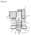
- Fig. 10 is a view illustrating the state where the magnet receiver 9 is descended after the assembly 2 is formed.
- the assembly 2 according to this embodiment is formed by three magnet pieces 3, each of which do not have a chamfered ridge line, and a dummy workpiece 15 as a front member, whose ridge lines are respectively chamfered.
- a housing unit 16 for housing the dummy workpiece 15 is provided in the rotor core support disk 5.
- the depth of the housing unit 16 is equal to the thickness of the dummy workpiece 15 in the insertion direction.
- the dummy workpiece 15 is arranged on the magnet receiver 9, and three magnet pieces 3 are laminated thereon, thus forming the state of Fig. 9 .
- the magnet alignment rods 10 are abutted.
- both of the dummy workpiece 15 and the magnet pieces 3 are pressed against the magnet piece reference surfaces 8, and the alignment is made in such a manner that, when being projected from the side of the insertion hole 6, the three magnet pieces 3 are hidden inside the projection of the dummy workpiece 15.
- the magnet receiver 9 When the dummy workpiece 15 and the magnet pieces 3 are aligned, the magnet receiver 9 is descended to the position lower than the rotor core support disk 5. Thereby, the dummy workpiece 15 is housed in the housing unit 16, and the three magnet pieces 3 remain in the magnet insertion hole 6.
- the magnet pieces 3 are inserted to the lower end of the magnet insertion hole 6, without being stuck, as the dummy workpiece 15 has the chamfering portions.
- the assembly 2 is moved along the insertion direction until the dummy workpiece 15 passes through the magnet insertion hole 6, and therefore the dummy workpiece 15 does not remain inside the rotor core 4.
Landscapes
- Engineering & Computer Science (AREA)
- Manufacturing & Machinery (AREA)
- Power Engineering (AREA)
- Permanent Field Magnets Of Synchronous Machinery (AREA)
- Manufacture Of Motors, Generators (AREA)
Abstract
Description
- The present invention relates to a technique of inserting a magnet into a rotor core of an electric motor.
- Permanent magnet type synchronous motors, in which permanent magnets are embedded in rotors (hereinafter referred to as "PM motors"), are well known as electric motors used in electric vehicles and the like. Further, methods of reducing eddy current loss by dividing the magnets to be embedded are well known as methods of improving efficiency of the PM motors. According to
WO2001/095460 , for example, magnet pieces that are divided into a plurality of pieces are adhered to each other to form one long plate-shaped magnet, and this long plate-shaped magnet is inserted into a magnet insertion hole in a rotor core. - According to the above-described literature, the magnet pieces are adhered to each other by aligning the magnet pieces in an outer frame that is formed by organic resin, and applying pressure and heat and the like from the outside, so as to form the long plate-shaped magnet. This results in high manufacturing costs required for forming the long plate-shaped magnet.
- However, when the magnet pieces are separately inserted into the magnet insertion hole in the rotor core in order to reduce the costs required for forming the long plate-shaped magnet, the magnet pieces get easily stuck in the middle of the magnet insertion hole and do not reach the bottom of the insertion hole, in the case where corners of the magnet pieces are not subjected to chamfering. On the other hand, when the corners of all the magnet pieces to be inserted are subjected to the chamfering, cost of the chamfering increases greatly, and performance of the magnet deteriorates due to a reduction in magnet volume by the chamfering.
- The present invention is made in view of the above-described problems, and an object of the present invention is to provide a method of inserting magnet pieces into a magnet insertion hole, while suppressing increase in costs and deterioration of performance.
- According to one embodiment of this invention, a magnet insertion method into a rotor core for inserting an assembly into a magnet insertion hole provided in the rotor core of an electric motor, the assembly being formed by laminating a plurality of members, including at least a plurality of magnet pieces, in a line, the magnet insertion method comprising; forming the assembly by arranging a front member, having a surface surrounded by a chamfered ridge line, to cause the surface to be a front side end surface upon insertion, by laminating, on a rear side of the front member in an insertion direction, other members, without having the chamfered ridge line, in a line along the insertion direction to cause the other members to be hidden inside a projection of the front member when being projected from an insertion hole side, and by temporarily holding the front member and the other members.
-
Fig. 1 is a schematic block diagram of a magnet insertion device, to which a first embodiment is applied; -
Fig. 2 is a view illustrating a plurality of magnet pieces to be inserted; -
Fig. 3 is a schematic view of an assembly according to the first embodiment; -
Fig. 4 is a first view explaining operation of the magnet insertion device; -
Fig. 5 is a second view explaining the operation of the magnet insertion device; -
Fig. 6 is a third view explaining the operation of the magnet insertion device; -
Fig. 7 is a fourth view explaining the operation of the magnet insertion device; -
Fig. 8 is a view illustrating another example of an assembly; -
Fig. 9 is a schematic view of the assembly according to a second embodiment; and -
Fig. 10 is a schematic block diagram of the magnet insertion device, to which the second embodiment is applied. - Hereinafter, embodiments of the present invention will be explained with reference to the attached drawings.
-
Fig. 1 is a schematic block diagram of a magnet insertion device 1 that is used in a first embodiment. The magnet insertion device 1 is a device for inserting anassembly 2 that is formed by laminating a plurality ofmagnet pieces 3 as a tip member or another member into amagnet insertion hole 6 in arotor core 4 that is formed by laminated steel sheets. Theassembly 2 will be described in detail later. - The magnet insertion device 1 is provided with a rotor
core support disk 5 that holds therotor core 4, amagnet receiver 9 that holds theassembly 2 and serves as an assembly receiving member, analignment jig 7 that holds side surfaces of theassembly 2, and amagnet alignment rod 10 that presses theassembly 2 against thealignment jig 7. - The
magnet receiver 9, driven by a magnetreceiver drive unit 13, moves along an axis of themagnet insertion hole 6 from the lower side to the upper side of themagnet insertion hole 6. In order to prevent themagnet pieces 3, aligned by a method that will be described later, from being misaligned during driving, the magnetreceiver drive unit 13 is supposed to be a unit that does not produce vibration, such as an air cylinder. - The
magnet alignment rod 10, driven by an alignmentrod drive unit 12, moves in the direction perpendicular to the axis of themagnet insertion hole 6. Thealignment jig 7, driven by an alignment jiglinear motion unit 14, moves in the direction perpendicular to the axis of themagnet insertion hole 6. - The
alignment jig 7 has a surface that faces against the side surface on the right side of theassembly 2 in the drawing, and a surface that faces against the side surface on the back side of theassembly 2 in the drawing. In addition to themagnet alignment rod 10 and the alignmentrod drive unit 12 as illustrated inFig. 1 , ones that move from the front side to the back side in the drawing are also provided. - The rotor
core support disk 5 has an opening 5A at a position corresponding to themagnet insertion hole 6 in therotor core 4, the opening 5A being smaller than the cross section of theassembly 2 crossing the axis of themagnet insertion hole 6, as will be described later. - Now, an explanation will be given to the
assembly 2. -
Fig. 2 and Fig. 3 are views for explaining theassembly 2. Arrows in the drawings indicate the direction of movement when theassembly 2 is inserted into the magnet insertion hole 6 (hereinafter referred to as the insertion direction). - The
assembly 2 is formed by laminating themagnet pieces 3, divided into a plurality of pieces, in a line along the insertion direction. Themagnet piece 3, to be the front piece upon insertion, has its surface surrounded by a chamfered ridge line, and is arranged in such a manner that the surface surrounded by the chamfered ridge line becomes the front side end surface upon insertion. The second and thethird magnet pieces 3 from the insertion direction do not have the chamfered ridge line. The second and thethird magnet pieces 3 from the insertion direction are arranged in such a manner that, when theassembly 2 is projected from the insertion direction, the second and thethird magnet pieces 3 are hidden inside the projection of thefront magnet piece 3. Incidentally, in this case, it is supposed that the projections of all themagnet pieces 3 included in theassembly 2 have the same shape when being projected from the side of themagnet insertion hole 6. - Next, operation of the magnet insertion device 1 will be explained with reference to
Fig. 4 to Fig. 7 . Incidentally, inFig. 4 to Fig. 7 , the alignmentrod drive units 12, the magnetreceiver drive unit 13 and the alignment jiglinear motion unit 14 are omitted. - Initially, as illustrated in
Fig. 4 , themagnet receiver 9 is located at a position lower than the rotorcore support disk 5, and themagnet alignment rods 10 and thealignment jig 7 are located outward in a radial direction of themagnet insertion hole 6. - In this state, the
rotor core 4 is arranged on the rotorcore support disk 5, and themagnet receiver 9 is ascended to a position higher than the upper end surface of therotor core 4. - When the
magnet receiver 9 is ascended as illustrated inFig. 5 , themagnet pieces 3 are laminated on theascended magnet receiver 9 in the same order as that ofFig. 3 . Themagnet pieces 3 are supplied in order by a not-illustrated supply device, such as a robot arm, for example. When interference between the supply device and thealignment jig 7 occurs at this time, thealignment jig 7 is moved further outward in the radial direction of themagnet insertion hole 6. - When the
magnet pieces 3 are laminated, thealignment jig 7 is moved so that the surfaces of thealignment jig 7 abutting against the magnet pieces 3 (hereinafter referred to as magnet piece reference surfaces 8), in the right/left direction and the front/back direction in the drawing, are lined up with the wall of themagnet insertion hole 6. Incidentally, the magnetpiece reference surfaces 8 may be closer to the center of themagnet insertion hole 6 by about 0.01 mm than the wall of themagnet insertion hole 6. - In addition, the
alignment jig 7 and themagnet alignment rods 10 may have such shape and arrangement that are able to prevent themagnet piece 3 from dropping from themagnet receiver 9 or from thelower magnet piece 3, so as to avoid a fall of the laminatedmagnet pieces 3. - When the lamination of the
magnet pieces 3 is finished, themagnet alignment rods 10 are pressed against themagnet pieces 3, as illustrated inFig. 6 , so as to align the laminatedmagnet pieces 3 along the magnetpiece reference surfaces 8. Thereby, the second and thethird magnet pieces 3 from the bottom are hidden inside thefront magnet piece 3, when being projected from the side of themagnet insertion hole 6. When interference between themagnet alignment rods 10 occurs, one of themagnet alignment rods 10 is retracted. - Incidentally, it is also suitable to cause the magnet
piece reference surfaces 8 to line up with the wall of themagnet insertion hole 6 and to move themagnet alignment rods 10, before laminating themagnet pieces 3, so that the alignment is finished when the lamination is finished. - When the alignment of the
magnet pieces 3 is finished, that is, when theassembly 2 is formed, as illustrated inFig. 7 , themagnet receiver 9 is descended to a position lower than the lower end of therotor core 4. Theassembly 2 remains inside themagnet insertion hole 6 as it is get stuck over the opening 5A of the rotorcore support disk 5, and the insertion of themagnet pieces 3 into themagnet insertion hole 6 is thus finished. - With regard to the
assembly 2, the tip surface is chamfered and the plurality ofmagnet pieces 3 are aligned in such a manner that the second and thethird magnet pieces 3 are hidden inside thefront magnet piece 3, when being projected from the side of themagnet insertion hole 6, as described above. Supposing that theassembly 2 comes in contact with the wall of themagnet insertion hole 6, at the time of descending themagnet receiver 9, the surface that comes in contact with the wall is the chamfered front side end surface. Thus, theassembly 2 reaches the lower end of themagnet insertion hole 6, without being stuck in the middle. As it is not necessary to chamfer the second and thethird magnet pieces 3 from the bottom, the costs required for the chamfering can be reduced. -
Fig. 8 is a view illustrating another example of theassembly 2, to which this embodiment can be applied. The difference from theassembly 2 ofFig. 3 is that, when being projected from the side of themagnet insertion hole 6, the projection of thefront magnet piece 3 is larger than the projections of the second and thethird magnet pieces 3 from the bottom, and that a difference in level is formed between thefront magnet piece 3 and themagnet piece 3 second from the bottom. It is also possible to insert theassembly 2 like this into themagnet insertion hole 6 by the above-described process. Incidentally, when using theassembly 2 ofFig. 8 , it is preferable that each of themagnet alignment rods 10 and thealignment jig 7, at the position abutting against themagnet pieces 3, be formed to have a shape corresponding to the difference in level formed between thefront magnet piece 3 and themagnet piece 3 second from the bottom. For example, as illustrated inFig. 10 that will be described later, it is preferable to form thealignment jig 7 to have flat surfaces, and each of themagnet alignment rods 10 to have such a shape that corresponds to the difference in level formed on the side surface of themagnet alignment rod 10 of theassembly 2 when the plurality ofmagnet pieces 3 are abutted against thealignment jig 7. - Next, effects of the above-described magnet insertion method will be explained.
- The
front magnet piece 3, having the surface surrounded by the chamfered ridge line, is arranged to be the front side end surface upon insertion and, on the back side thereof along the insertion direction,other magnet pieces 3, without having the chamfered ridge line, are laminated. Further, the plurality ofmagnet pieces 3 are aligned in a line along the insertion direction so that, when being projected from the side of the insertion hole, theother magnet pieces 3 are hidden inside the projection of thefront magnet piece 3. Then, the plurality ofmagnet pieces 3 are held temporarily, while being aligned as described above, and thus theassembly 2 is formed. - It should be noted that the term "held temporarily" means the state where the plurality of
magnet pieces 3 are laminated on themagnet receiver 9, without being adhered to each other by an adhesive, nor being formed integrally by resin molding or the like. - With the
assembly 2 like this, edge portions of themagnet pieces 3 that are not chamfered are not exposed when viewed from the side of themagnet insertion hole 6, and the chamfered portion, provided on thefront magnet piece 3, serves as a guide. Thus, theassembly 2 is inserted to the lower end of themagnet insertion hole 6, without being stuck in the middle against the inner wall of themagnet insertion hole 6. As the chamfering processing is applied to thefront magnet piece 3 only, it is possible to suppress reduction in the volume of the magnet by the chamfering processing, and to avoid deterioration of performance of the magnet. In addition, it is possible to reduce the costs required for the chamfering processing. - Similar effects to those described above can also be obtained when the projected area of the second and the
third magnet pieces 3 from the bottom, being projected from the side of the insertion hole, is smaller than the projected area of thefront magnet piece 3, being projected from the side of the insertion hole. - The
rotor core 4 is arranged in such a manner that the axis of themagnet insertion hole 6 extends in the vertical direction, and thealignment jig 7 that holds at least two side surfaces of theassembly 2, the side surfaces being perpendicular to each other, and themagnet receiver 9 that holds the front side end surface of theassembly 2 upon insertion are arranged at a position higher than themagnet insertion hole 6. The plurality ofmagnet pieces 3 are laminated on themagnet receiver 9 and aligned by being pressed by themagnet alignment rods 10 from directions opposing thealignment jig 7, so as to form theassembly 2. Thus, the alignment of themagnet pieces 3 can be made accurately. - Further, the
assembly 2 is not stuck against the wall of themagnet insertion hole 6, as described above. Therefore, even though themagnet pieces 3 are held temporarily, without being adhered to each other, theassembly 2 is integrally descended by the action of gravity when themagnet receiver 9 is descended, and reaches the lower end of themagnet insertion hole 6. - This embodiment is different from the first embodiment in the structure of the
assembly 2 and accordingly, a part of the structure of the magnet insertion device 1. Hereinafter, differences from the first embodiment will mainly be explained. -
Fig. 9 is a schematic block diagram of theassembly 2 according to this embodiment.Fig. 10 is a view illustrating the state where themagnet receiver 9 is descended after theassembly 2 is formed. - The
assembly 2 according to this embodiment is formed by threemagnet pieces 3, each of which do not have a chamfered ridge line, and adummy workpiece 15 as a front member, whose ridge lines are respectively chamfered. - On the side surface of the
magnet alignment rod 10 on the side of theassembly 2, there is provided a difference in level, corresponding to a difference in level formed between the side surface of thedummy workpiece 15 on the sides of themagnet alignment rods 10 and the side surfaces of themagnet pieces 3 on the sides of themagnet alignment rods 10, when thedummy workpiece 15 and themagnet pieces 3 are abutted against the magnet piece reference surfaces 8. - A housing unit 16 for housing the
dummy workpiece 15 is provided in the rotorcore support disk 5. The depth of the housing unit 16 is equal to the thickness of thedummy workpiece 15 in the insertion direction. - First, the
dummy workpiece 15 is arranged on themagnet receiver 9, and threemagnet pieces 3 are laminated thereon, thus forming the state ofFig. 9 . Then, themagnet alignment rods 10 are abutted. As the above-described difference in level is formed in the side surfaces of themagnet alignment rods 10 on the side of theassembly 2, both of thedummy workpiece 15 and themagnet pieces 3 are pressed against the magnet piece reference surfaces 8, and the alignment is made in such a manner that, when being projected from the side of theinsertion hole 6, the threemagnet pieces 3 are hidden inside the projection of thedummy workpiece 15. - When the
dummy workpiece 15 and themagnet pieces 3 are aligned, themagnet receiver 9 is descended to the position lower than the rotorcore support disk 5. Thereby, thedummy workpiece 15 is housed in the housing unit 16, and the threemagnet pieces 3 remain in themagnet insertion hole 6. - According to this embodiment, similarly to the first embodiment, the
magnet pieces 3 are inserted to the lower end of themagnet insertion hole 6, without being stuck, as thedummy workpiece 15 has the chamfering portions. - Further, the
assembly 2 is moved along the insertion direction until the dummy workpiece 15 passes through themagnet insertion hole 6, and therefore thedummy workpiece 15 does not remain inside therotor core 4. - The embodiments of the present invention have been explained thus far. However, the above embodiments are only a part of application examples of the present invention, and are not intended to limit the technical scope of the present invention to the concrete structures of the above-described embodiments.
- This application claims priority from
Japanese Patent Application No. 2013-96555
Claims (6)
- A magnet insertion method into a rotor core for inserting an assembly into a magnet insertion hole provided in the rotor core of an electric motor, the assembly being formed by laminating a plurality of members, including at least a plurality of magnet pieces, in a line, the magnet insertion method comprising
forming the assembly by arranging a front member, having a surface surrounded by a chamfered ridge line, to cause the surface to be a front side end surface upon insertion, by laminating, on a rear side of the front member in an insertion direction, other members, without having the chamfered ridge line, in a line along the insertion direction to cause the other members to be hidden inside a projection of the front member when being projected from an insertion hole side, and by temporarily holding the front member and the other members. - The magnet insertion method into the rotor core according to claim 1,
wherein a projected area of the other members, when being projected from the insertion hole side, is smaller than a projected area of the front member, when being projected from the insertion hole side. - The magnet insertion method into the rotor core according to claim 1 or claim 2,
wherein all of the plurality of members are magnets. - The magnet insertion method into the rotor core according to claim 1 or claim 2,
wherein the front member is a dummy workpiece, and all the other members are magnets without having the chamfered ridge line. - The magnet insertion method into the rotor core according to claim 4,
wherein the front member and the other members are moved in the insertion direction until the front member passes through the magnet insertion hole. - The magnet insertion method into the rotor core according to any one of claim 1 to claim 5,
wherein the rotor core is arranged to cause an axis of the magnet insertion hole to extend in a vertical direction,
wherein an alignment jig for holding at least two side surfaces of the assembly, the side surfaces being perpendicular to each other, and an assembly receiving member for holding the front side end surface of the assembly upon insertion are arranged at a position higher than the magnet insertion hole, and
wherein the plurality of members are laminated on the assembly receiving member and aligned by being pressed by a magnet alignment rod from a direction opposing the alignment jig, so as to form the assembly.
Applications Claiming Priority (2)
| Application Number | Priority Date | Filing Date | Title |
|---|---|---|---|
| JP2013096555 | 2013-05-01 | ||
| PCT/JP2014/058978 WO2014178246A1 (en) | 2013-05-01 | 2014-03-27 | Method for inserting magnet into rotor core |
Publications (3)
| Publication Number | Publication Date |
|---|---|
| EP2993768A1 true EP2993768A1 (en) | 2016-03-09 |
| EP2993768A4 EP2993768A4 (en) | 2016-04-20 |
| EP2993768B1 EP2993768B1 (en) | 2017-08-09 |
Family
ID=51843381
Family Applications (1)
| Application Number | Title | Priority Date | Filing Date |
|---|---|---|---|
| EP14792072.2A Active EP2993768B1 (en) | 2013-05-01 | 2014-03-27 | Method for inserting magnet into rotor core |
Country Status (5)
| Country | Link |
|---|---|
| US (1) | US9929628B2 (en) |
| EP (1) | EP2993768B1 (en) |
| JP (1) | JP5987978B2 (en) |
| CN (1) | CN105144553B (en) |
| WO (1) | WO2014178246A1 (en) |
Cited By (2)
| Publication number | Priority date | Publication date | Assignee | Title |
|---|---|---|---|---|
| WO2018202497A1 (en) * | 2017-05-05 | 2018-11-08 | Thyssenkrupp System Engineering Gmbh | Assembly device for fitting a rotor unit with magnet elements |
| DE102020205513A1 (en) | 2020-04-30 | 2021-11-04 | Vitesco Technologies GmbH | Magnet holder, rotor, stator and electric motor |
Families Citing this family (11)
| Publication number | Priority date | Publication date | Assignee | Title |
|---|---|---|---|---|
| JP5929153B2 (en) * | 2011-12-14 | 2016-06-01 | 日産自動車株式会社 | Field pole magnet body manufacturing apparatus and method |
| JP6369420B2 (en) | 2015-08-07 | 2018-08-08 | トヨタ自動車株式会社 | Manufacturing method of rotor |
| CN106953443B (en) * | 2017-03-28 | 2023-11-28 | 安徽美芝制冷设备有限公司 | Rotors for motors, motors and compressors |
| JP2019160973A (en) * | 2018-03-12 | 2019-09-19 | オムロン株式会社 | Component insertion device, component insertion method, and program |
| CN110932500B (en) * | 2019-12-31 | 2025-06-03 | 浙江联宜电机有限公司 | Magnetic tile device on rotor |
| JP2022023737A (en) | 2020-07-27 | 2022-02-08 | トヨタ自動車株式会社 | Assembly method of rotor and control apparatus of rotor assembly device |
| JP7362042B2 (en) | 2020-09-17 | 2023-10-17 | トヨタ自動車株式会社 | Rotor manufacturing method |
| JP7484812B2 (en) * | 2021-05-20 | 2024-05-16 | トヨタ自動車株式会社 | Rotor manufacturing method and rotor manufacturing apparatus |
| JP7484822B2 (en) * | 2021-06-09 | 2024-05-16 | 株式会社デンソー | Magnet Assembly Device |
| JP7537371B2 (en) * | 2021-06-09 | 2024-08-21 | 株式会社デンソー | Magnet assembly device and magnet assembly method |
| CN117833573A (en) * | 2023-03-29 | 2024-04-05 | 纪成伟 | Preparation method of composite permanent magnet material |
Family Cites Families (11)
| Publication number | Priority date | Publication date | Assignee | Title |
|---|---|---|---|---|
| US4910861A (en) * | 1988-10-07 | 1990-03-27 | Emerson Electric Co. | Method of manufacturing retention structure for electric motor rotor magnets |
| JP3351237B2 (en) * | 1996-05-16 | 2002-11-25 | 三菱電機株式会社 | Permanent magnet type motor |
| JP3072504B2 (en) * | 1996-07-18 | 2000-07-31 | アイチ−エマソン電機株式会社 | Motor rotor |
| JPH10174326A (en) * | 1996-12-06 | 1998-06-26 | Matsushita Electric Ind Co Ltd | Motor rotor with embedded permanent magnet and method of manufacturing the same |
| JPH10290542A (en) * | 1997-04-11 | 1998-10-27 | Aichi Emerson Electric Co Ltd | Motor |
| JPWO2001095460A1 (en) | 2000-06-09 | 2004-01-15 | 住友特殊金属株式会社 | Integrated magnet body and motor incorporating it |
| JP5469481B2 (en) | 2010-02-26 | 2014-04-16 | トヨタ紡織株式会社 | Method and apparatus for inserting magnet material into magnet hole of motor core |
| JP2012039746A (en) * | 2010-08-06 | 2012-02-23 | Nissan Motor Co Ltd | Magnet insertion method, rotor, and motor |
| JP5746873B2 (en) * | 2011-02-02 | 2015-07-08 | 本田技研工業株式会社 | Manufacturing method of rotor |
| EP2677641B1 (en) | 2011-02-14 | 2018-07-04 | Toyota Jidosha Kabushiki Kaisha | Manufacturing method of a rotor with permanent magnets |
| JP2013096555A (en) | 2011-11-04 | 2013-05-20 | Fine Mec:Kk | Connecting mechanism for driving device or the like |
-
2014
- 2014-03-27 US US14/787,985 patent/US9929628B2/en active Active
- 2014-03-27 CN CN201480021234.2A patent/CN105144553B/en active Active
- 2014-03-27 WO PCT/JP2014/058978 patent/WO2014178246A1/en not_active Ceased
- 2014-03-27 EP EP14792072.2A patent/EP2993768B1/en active Active
- 2014-03-27 JP JP2015514785A patent/JP5987978B2/en active Active
Cited By (2)
| Publication number | Priority date | Publication date | Assignee | Title |
|---|---|---|---|---|
| WO2018202497A1 (en) * | 2017-05-05 | 2018-11-08 | Thyssenkrupp System Engineering Gmbh | Assembly device for fitting a rotor unit with magnet elements |
| DE102020205513A1 (en) | 2020-04-30 | 2021-11-04 | Vitesco Technologies GmbH | Magnet holder, rotor, stator and electric motor |
Also Published As
| Publication number | Publication date |
|---|---|
| EP2993768A4 (en) | 2016-04-20 |
| CN105144553A (en) | 2015-12-09 |
| US20160111944A1 (en) | 2016-04-21 |
| EP2993768B1 (en) | 2017-08-09 |
| JP5987978B2 (en) | 2016-09-07 |
| JPWO2014178246A1 (en) | 2017-02-23 |
| CN105144553B (en) | 2017-11-28 |
| WO2014178246A1 (en) | 2014-11-06 |
| US9929628B2 (en) | 2018-03-27 |
Similar Documents
| Publication | Publication Date | Title |
|---|---|---|
| EP2993768B1 (en) | Method for inserting magnet into rotor core | |
| CN104993650B (en) | Magnet steel drawing-in device | |
| US9899148B2 (en) | Manufacturing device for field pole magnet body and manufacturing method for same | |
| JP2019149934A (en) | Permanent magnet piece | |
| US11117757B2 (en) | Linear conveyor device | |
| CN208209778U (en) | Linear motor | |
| CN115995929B (en) | Linear type halbach array assembling device and assembling method | |
| EP2790305B1 (en) | Manufacturing device for field pole magnet body and manufacturing method for same | |
| EP2811628A1 (en) | Method for manufacturing magnet pieces for forming field-pole magnets | |
| US10118212B2 (en) | Method for forming blanked piece and manufacturing method of laminated body and laminated iron core using blanked piece formed by method for forming blanked piece | |
| JP2001169529A (en) | Mobiles and mobile systems | |
| JP5365775B2 (en) | Manufacturing method of linear motor system and linear motor system | |
| JP5553247B2 (en) | Linear slider | |
| CN118617172B (en) | Triaxial rapid cutter servo device driven by normal stress electromagnetic drive and using method thereof | |
| JP6546486B2 (en) | Rotor iron core magnet insertion device and magnet insertion method therefor | |
| KR101991462B1 (en) | Straight type linear actuator | |
| CN103701294A (en) | Motor driven equipment | |
| KR101717119B1 (en) | a insert device for magnet | |
| CN107470882B (en) | Automatic picture peg mechanism of integrated shaped steel tip | |
| CN206302274U (en) | A kind of high-speed motion device | |
| CN105072842A (en) | Terminal housing and terminal | |
| CN204669198U (en) | Linear motor moving module and stator structure thereof | |
| JP5994447B2 (en) | Magnet piece manufacturing apparatus constituting field pole magnet body and manufacturing method thereof | |
| CN104969445B (en) | For method manufacturing of electric machines, device and equipment | |
| JP2021019425A (en) | Manufacturing method of rotor |
Legal Events
| Date | Code | Title | Description |
|---|---|---|---|
| PUAI | Public reference made under article 153(3) epc to a published international application that has entered the european phase |
Free format text: ORIGINAL CODE: 0009012 |
|
| 17P | Request for examination filed |
Effective date: 20151127 |
|
| AK | Designated contracting states |
Kind code of ref document: A1 Designated state(s): AL AT BE BG CH CY CZ DE DK EE ES FI FR GB GR HR HU IE IS IT LI LT LU LV MC MK MT NL NO PL PT RO RS SE SI SK SM TR |
|
| AX | Request for extension of the european patent |
Extension state: BA ME |
|
| A4 | Supplementary search report drawn up and despatched |
Effective date: 20160323 |
|
| RIC1 | Information provided on ipc code assigned before grant |
Ipc: H02K 15/03 20060101AFI20160317BHEP |
|
| DAX | Request for extension of the european patent (deleted) | ||
| GRAP | Despatch of communication of intention to grant a patent |
Free format text: ORIGINAL CODE: EPIDOSNIGR1 |
|
| INTG | Intention to grant announced |
Effective date: 20170406 |
|
| GRAS | Grant fee paid |
Free format text: ORIGINAL CODE: EPIDOSNIGR3 |
|
| GRAA | (expected) grant |
Free format text: ORIGINAL CODE: 0009210 |
|
| RIN1 | Information on inventor provided before grant (corrected) |
Inventor name: OHSHIMA, TAKUMI Inventor name: KISHI, MICHITO Inventor name: HASEGAWA, KIYOSHI Inventor name: MATSUSHITA, YASUSHI Inventor name: SHIBUKAWA, HIROAKI Inventor name: HORI, AKIHISA Inventor name: SEKIKAWA, TAKASHI |
|
| AK | Designated contracting states |
Kind code of ref document: B1 Designated state(s): AL AT BE BG CH CY CZ DE DK EE ES FI FR GB GR HR HU IE IS IT LI LT LU LV MC MK MT NL NO PL PT RO RS SE SI SK SM TR |
|
| REG | Reference to a national code |
Ref country code: GB Ref legal event code: FG4D |
|
| REG | Reference to a national code |
Ref country code: CH Ref legal event code: EP Ref country code: AT Ref legal event code: REF Ref document number: 917820 Country of ref document: AT Kind code of ref document: T Effective date: 20170815 |
|
| REG | Reference to a national code |
Ref country code: IE Ref legal event code: FG4D |
|
| REG | Reference to a national code |
Ref country code: DE Ref legal event code: R096 Ref document number: 602014012997 Country of ref document: DE |
|
| REG | Reference to a national code |
Ref country code: NL Ref legal event code: MP Effective date: 20170809 |
|
| REG | Reference to a national code |
Ref country code: LT Ref legal event code: MG4D |
|
| REG | Reference to a national code |
Ref country code: AT Ref legal event code: MK05 Ref document number: 917820 Country of ref document: AT Kind code of ref document: T Effective date: 20170809 |
|
| PG25 | Lapsed in a contracting state [announced via postgrant information from national office to epo] |
Ref country code: NL Free format text: LAPSE BECAUSE OF FAILURE TO SUBMIT A TRANSLATION OF THE DESCRIPTION OR TO PAY THE FEE WITHIN THE PRESCRIBED TIME-LIMIT Effective date: 20170809 Ref country code: HR Free format text: LAPSE BECAUSE OF FAILURE TO SUBMIT A TRANSLATION OF THE DESCRIPTION OR TO PAY THE FEE WITHIN THE PRESCRIBED TIME-LIMIT Effective date: 20170809 Ref country code: AT Free format text: LAPSE BECAUSE OF FAILURE TO SUBMIT A TRANSLATION OF THE DESCRIPTION OR TO PAY THE FEE WITHIN THE PRESCRIBED TIME-LIMIT Effective date: 20170809 Ref country code: NO Free format text: LAPSE BECAUSE OF FAILURE TO SUBMIT A TRANSLATION OF THE DESCRIPTION OR TO PAY THE FEE WITHIN THE PRESCRIBED TIME-LIMIT Effective date: 20171109 Ref country code: SE Free format text: LAPSE BECAUSE OF FAILURE TO SUBMIT A TRANSLATION OF THE DESCRIPTION OR TO PAY THE FEE WITHIN THE PRESCRIBED TIME-LIMIT Effective date: 20170809 Ref country code: LT Free format text: LAPSE BECAUSE OF FAILURE TO SUBMIT A TRANSLATION OF THE DESCRIPTION OR TO PAY THE FEE WITHIN THE PRESCRIBED TIME-LIMIT Effective date: 20170809 Ref country code: FI Free format text: LAPSE BECAUSE OF FAILURE TO SUBMIT A TRANSLATION OF THE DESCRIPTION OR TO PAY THE FEE WITHIN THE PRESCRIBED TIME-LIMIT Effective date: 20170809 |
|
| REG | Reference to a national code |
Ref country code: FR Ref legal event code: PLFP Year of fee payment: 5 |
|
| PG25 | Lapsed in a contracting state [announced via postgrant information from national office to epo] |
Ref country code: RS Free format text: LAPSE BECAUSE OF FAILURE TO SUBMIT A TRANSLATION OF THE DESCRIPTION OR TO PAY THE FEE WITHIN THE PRESCRIBED TIME-LIMIT Effective date: 20170809 Ref country code: IS Free format text: LAPSE BECAUSE OF FAILURE TO SUBMIT A TRANSLATION OF THE DESCRIPTION OR TO PAY THE FEE WITHIN THE PRESCRIBED TIME-LIMIT Effective date: 20171209 Ref country code: PL Free format text: LAPSE BECAUSE OF FAILURE TO SUBMIT A TRANSLATION OF THE DESCRIPTION OR TO PAY THE FEE WITHIN THE PRESCRIBED TIME-LIMIT Effective date: 20170809 Ref country code: BG Free format text: LAPSE BECAUSE OF FAILURE TO SUBMIT A TRANSLATION OF THE DESCRIPTION OR TO PAY THE FEE WITHIN THE PRESCRIBED TIME-LIMIT Effective date: 20171109 Ref country code: LV Free format text: LAPSE BECAUSE OF FAILURE TO SUBMIT A TRANSLATION OF THE DESCRIPTION OR TO PAY THE FEE WITHIN THE PRESCRIBED TIME-LIMIT Effective date: 20170809 Ref country code: GR Free format text: LAPSE BECAUSE OF FAILURE TO SUBMIT A TRANSLATION OF THE DESCRIPTION OR TO PAY THE FEE WITHIN THE PRESCRIBED TIME-LIMIT Effective date: 20171110 Ref country code: ES Free format text: LAPSE BECAUSE OF FAILURE TO SUBMIT A TRANSLATION OF THE DESCRIPTION OR TO PAY THE FEE WITHIN THE PRESCRIBED TIME-LIMIT Effective date: 20170809 |
|
| PG25 | Lapsed in a contracting state [announced via postgrant information from national office to epo] |
Ref country code: DK Free format text: LAPSE BECAUSE OF FAILURE TO SUBMIT A TRANSLATION OF THE DESCRIPTION OR TO PAY THE FEE WITHIN THE PRESCRIBED TIME-LIMIT Effective date: 20170809 Ref country code: CZ Free format text: LAPSE BECAUSE OF FAILURE TO SUBMIT A TRANSLATION OF THE DESCRIPTION OR TO PAY THE FEE WITHIN THE PRESCRIBED TIME-LIMIT Effective date: 20170809 Ref country code: RO Free format text: LAPSE BECAUSE OF FAILURE TO SUBMIT A TRANSLATION OF THE DESCRIPTION OR TO PAY THE FEE WITHIN THE PRESCRIBED TIME-LIMIT Effective date: 20170809 |
|
| REG | Reference to a national code |
Ref country code: DE Ref legal event code: R097 Ref document number: 602014012997 Country of ref document: DE |
|
| PG25 | Lapsed in a contracting state [announced via postgrant information from national office to epo] |
Ref country code: SM Free format text: LAPSE BECAUSE OF FAILURE TO SUBMIT A TRANSLATION OF THE DESCRIPTION OR TO PAY THE FEE WITHIN THE PRESCRIBED TIME-LIMIT Effective date: 20170809 Ref country code: IT Free format text: LAPSE BECAUSE OF FAILURE TO SUBMIT A TRANSLATION OF THE DESCRIPTION OR TO PAY THE FEE WITHIN THE PRESCRIBED TIME-LIMIT Effective date: 20170809 Ref country code: EE Free format text: LAPSE BECAUSE OF FAILURE TO SUBMIT A TRANSLATION OF THE DESCRIPTION OR TO PAY THE FEE WITHIN THE PRESCRIBED TIME-LIMIT Effective date: 20170809 Ref country code: SK Free format text: LAPSE BECAUSE OF FAILURE TO SUBMIT A TRANSLATION OF THE DESCRIPTION OR TO PAY THE FEE WITHIN THE PRESCRIBED TIME-LIMIT Effective date: 20170809 |
|
| PLBE | No opposition filed within time limit |
Free format text: ORIGINAL CODE: 0009261 |
|
| STAA | Information on the status of an ep patent application or granted ep patent |
Free format text: STATUS: NO OPPOSITION FILED WITHIN TIME LIMIT |
|
| 26N | No opposition filed |
Effective date: 20180511 |
|
| PG25 | Lapsed in a contracting state [announced via postgrant information from national office to epo] |
Ref country code: SI Free format text: LAPSE BECAUSE OF FAILURE TO SUBMIT A TRANSLATION OF THE DESCRIPTION OR TO PAY THE FEE WITHIN THE PRESCRIBED TIME-LIMIT Effective date: 20170809 |
|
| REG | Reference to a national code |
Ref country code: CH Ref legal event code: PL |
|
| PG25 | Lapsed in a contracting state [announced via postgrant information from national office to epo] |
Ref country code: MC Free format text: LAPSE BECAUSE OF FAILURE TO SUBMIT A TRANSLATION OF THE DESCRIPTION OR TO PAY THE FEE WITHIN THE PRESCRIBED TIME-LIMIT Effective date: 20170809 |
|
| REG | Reference to a national code |
Ref country code: BE Ref legal event code: MM Effective date: 20180331 |
|
| REG | Reference to a national code |
Ref country code: IE Ref legal event code: MM4A |
|
| PG25 | Lapsed in a contracting state [announced via postgrant information from national office to epo] |
Ref country code: LU Free format text: LAPSE BECAUSE OF NON-PAYMENT OF DUE FEES Effective date: 20180327 |
|
| PG25 | Lapsed in a contracting state [announced via postgrant information from national office to epo] |
Ref country code: IE Free format text: LAPSE BECAUSE OF NON-PAYMENT OF DUE FEES Effective date: 20180327 |
|
| PG25 | Lapsed in a contracting state [announced via postgrant information from national office to epo] |
Ref country code: BE Free format text: LAPSE BECAUSE OF NON-PAYMENT OF DUE FEES Effective date: 20180331 Ref country code: CH Free format text: LAPSE BECAUSE OF NON-PAYMENT OF DUE FEES Effective date: 20180331 Ref country code: LI Free format text: LAPSE BECAUSE OF NON-PAYMENT OF DUE FEES Effective date: 20180331 |
|
| PG25 | Lapsed in a contracting state [announced via postgrant information from national office to epo] |
Ref country code: MT Free format text: LAPSE BECAUSE OF NON-PAYMENT OF DUE FEES Effective date: 20180327 |
|
| PG25 | Lapsed in a contracting state [announced via postgrant information from national office to epo] |
Ref country code: TR Free format text: LAPSE BECAUSE OF FAILURE TO SUBMIT A TRANSLATION OF THE DESCRIPTION OR TO PAY THE FEE WITHIN THE PRESCRIBED TIME-LIMIT Effective date: 20170809 |
|
| PG25 | Lapsed in a contracting state [announced via postgrant information from national office to epo] |
Ref country code: PT Free format text: LAPSE BECAUSE OF FAILURE TO SUBMIT A TRANSLATION OF THE DESCRIPTION OR TO PAY THE FEE WITHIN THE PRESCRIBED TIME-LIMIT Effective date: 20170809 |
|
| PG25 | Lapsed in a contracting state [announced via postgrant information from national office to epo] |
Ref country code: CY Free format text: LAPSE BECAUSE OF FAILURE TO SUBMIT A TRANSLATION OF THE DESCRIPTION OR TO PAY THE FEE WITHIN THE PRESCRIBED TIME-LIMIT Effective date: 20170809 Ref country code: HU Free format text: LAPSE BECAUSE OF FAILURE TO SUBMIT A TRANSLATION OF THE DESCRIPTION OR TO PAY THE FEE WITHIN THE PRESCRIBED TIME-LIMIT; INVALID AB INITIO Effective date: 20140327 Ref country code: MK Free format text: LAPSE BECAUSE OF NON-PAYMENT OF DUE FEES Effective date: 20170809 |
|
| PG25 | Lapsed in a contracting state [announced via postgrant information from national office to epo] |
Ref country code: AL Free format text: LAPSE BECAUSE OF FAILURE TO SUBMIT A TRANSLATION OF THE DESCRIPTION OR TO PAY THE FEE WITHIN THE PRESCRIBED TIME-LIMIT Effective date: 20170809 |
|
| PGFP | Annual fee paid to national office [announced via postgrant information from national office to epo] |
Ref country code: GB Payment date: 20260220 Year of fee payment: 13 |
|
| PGFP | Annual fee paid to national office [announced via postgrant information from national office to epo] |
Ref country code: DE Payment date: 20260219 Year of fee payment: 13 |
|
| PGFP | Annual fee paid to national office [announced via postgrant information from national office to epo] |
Ref country code: FR Payment date: 20260219 Year of fee payment: 13 |