EP2993645A2 - Image processing program, information processing system, information processing apparatus, and image processing method - Google Patents
Image processing program, information processing system, information processing apparatus, and image processing method Download PDFInfo
- Publication number
- EP2993645A2 EP2993645A2 EP15176430.5A EP15176430A EP2993645A2 EP 2993645 A2 EP2993645 A2 EP 2993645A2 EP 15176430 A EP15176430 A EP 15176430A EP 2993645 A2 EP2993645 A2 EP 2993645A2
- Authority
- EP
- European Patent Office
- Prior art keywords
- image
- subject
- infrared
- region
- infrared image
- Prior art date
- Legal status (The legal status is an assumption and is not a legal conclusion. Google has not performed a legal analysis and makes no representation as to the accuracy of the status listed.)
- Granted
Links
Images







Classifications
-
- G—PHYSICS
- G06—COMPUTING OR CALCULATING; COUNTING
- G06T—IMAGE DATA PROCESSING OR GENERATION, IN GENERAL
- G06T7/00—Image analysis
- G06T7/10—Segmentation; Edge detection
- G06T7/136—Segmentation; Edge detection involving thresholding
-
- G—PHYSICS
- G06—COMPUTING OR CALCULATING; COUNTING
- G06T—IMAGE DATA PROCESSING OR GENERATION, IN GENERAL
- G06T7/00—Image analysis
- G06T7/70—Determining position or orientation of objects or cameras
- G06T7/73—Determining position or orientation of objects or cameras using feature-based methods
- G06T7/74—Determining position or orientation of objects or cameras using feature-based methods involving reference images or patches
-
- G—PHYSICS
- G06—COMPUTING OR CALCULATING; COUNTING
- G06T—IMAGE DATA PROCESSING OR GENERATION, IN GENERAL
- G06T7/00—Image analysis
- G06T7/10—Segmentation; Edge detection
- G06T7/11—Region-based segmentation
-
- G—PHYSICS
- G06—COMPUTING OR CALCULATING; COUNTING
- G06T—IMAGE DATA PROCESSING OR GENERATION, IN GENERAL
- G06T7/00—Image analysis
- G06T7/50—Depth or shape recovery
- G06T7/536—Depth or shape recovery from perspective effects, e.g. by using vanishing points
-
- G—PHYSICS
- G06—COMPUTING OR CALCULATING; COUNTING
- G06T—IMAGE DATA PROCESSING OR GENERATION, IN GENERAL
- G06T7/00—Image analysis
- G06T7/50—Depth or shape recovery
- G06T7/55—Depth or shape recovery from multiple images
- G06T7/571—Depth or shape recovery from multiple images from focus
-
- G—PHYSICS
- G06—COMPUTING OR CALCULATING; COUNTING
- G06T—IMAGE DATA PROCESSING OR GENERATION, IN GENERAL
- G06T7/00—Image analysis
- G06T7/90—Determination of colour characteristics
-
- H—ELECTRICITY
- H04—ELECTRIC COMMUNICATION TECHNIQUE
- H04N—PICTORIAL COMMUNICATION, e.g. TELEVISION
- H04N23/00—Cameras or camera modules comprising electronic image sensors; Control thereof
- H04N23/10—Cameras or camera modules comprising electronic image sensors; Control thereof for generating image signals from different wavelengths
- H04N23/11—Cameras or camera modules comprising electronic image sensors; Control thereof for generating image signals from different wavelengths for generating image signals from visible and infrared light wavelengths
-
- G—PHYSICS
- G06—COMPUTING OR CALCULATING; COUNTING
- G06T—IMAGE DATA PROCESSING OR GENERATION, IN GENERAL
- G06T2207/00—Indexing scheme for image analysis or image enhancement
- G06T2207/10—Image acquisition modality
- G06T2207/10004—Still image; Photographic image
- G06T2207/10012—Stereo images
-
- G—PHYSICS
- G06—COMPUTING OR CALCULATING; COUNTING
- G06T—IMAGE DATA PROCESSING OR GENERATION, IN GENERAL
- G06T2207/00—Indexing scheme for image analysis or image enhancement
- G06T2207/10—Image acquisition modality
- G06T2207/10024—Color image
-
- G—PHYSICS
- G06—COMPUTING OR CALCULATING; COUNTING
- G06T—IMAGE DATA PROCESSING OR GENERATION, IN GENERAL
- G06T2207/00—Indexing scheme for image analysis or image enhancement
- G06T2207/10—Image acquisition modality
- G06T2207/10028—Range image; Depth image; 3D point clouds
-
- G—PHYSICS
- G06—COMPUTING OR CALCULATING; COUNTING
- G06T—IMAGE DATA PROCESSING OR GENERATION, IN GENERAL
- G06T2207/00—Indexing scheme for image analysis or image enhancement
- G06T2207/10—Image acquisition modality
- G06T2207/10048—Infrared image
-
- G—PHYSICS
- G06—COMPUTING OR CALCULATING; COUNTING
- G06T—IMAGE DATA PROCESSING OR GENERATION, IN GENERAL
- G06T2207/00—Indexing scheme for image analysis or image enhancement
- G06T2207/10—Image acquisition modality
- G06T2207/10141—Special mode during image acquisition
- G06T2207/10144—Varying exposure
-
- G—PHYSICS
- G06—COMPUTING OR CALCULATING; COUNTING
- G06T—IMAGE DATA PROCESSING OR GENERATION, IN GENERAL
- G06T2207/00—Indexing scheme for image analysis or image enhancement
- G06T2207/10—Image acquisition modality
- G06T2207/10141—Special mode during image acquisition
- G06T2207/10152—Varying illumination
-
- G—PHYSICS
- G06—COMPUTING OR CALCULATING; COUNTING
- G06T—IMAGE DATA PROCESSING OR GENERATION, IN GENERAL
- G06T2207/00—Indexing scheme for image analysis or image enhancement
- G06T2207/20—Special algorithmic details
- G06T2207/20212—Image combination
- G06T2207/20224—Image subtraction
-
- G—PHYSICS
- G06—COMPUTING OR CALCULATING; COUNTING
- G06T—IMAGE DATA PROCESSING OR GENERATION, IN GENERAL
- G06T2207/00—Indexing scheme for image analysis or image enhancement
- G06T2207/30—Subject of image; Context of image processing
- G06T2207/30196—Human being; Person
Definitions
- the present invention relates to an image processing program capable of processing an infrared image, an information processing system, an information processing apparatus, and an image processing method.
- Japanese Patent Laying-Open No. 2005-350010 discloses a stereo vehicle exterior monitoring apparatus monitoring surroundings of a vehicle using stereo cameras constituted of a pair of infrared cameras.
- the apparatus shown in the prior art document calculates distance data with the use of the stereo infrared cameras and monitors a target based on the calculated distance data.
- stereo that is, a plurality of
- infrared cameras are required and there is a room for improvement in cost for mounting.
- An image processing program in an embodiment causes a computer to function as image obtaining means for obtaining an infrared image of a subject and position determination means for determining a position of the subject included in the infrared image based on brightness and a size of a prescribed region of the subject within the infrared image.
- the position determination means may determine a relative position of the subject with a reference position.
- the position determination means may determine the reference position based on an infrared image corresponding to the subject positioned in a reference state.
- the position determination means may determine a position of the subject based on the brightness of the prescribed region at the time when the size of the prescribed region satisfies a prescribed condition.
- the position determination means may determine a depth position of the subject in a direction of image pick-up by an image pick-up portion which obtains the infrared image, based on the brightness and the size of the prescribed region.
- the position determination means may determine the depth position and determine a position on a surface orthogonal to the direction of the subject based on a position of the prescribed region within the infrared image.
- the position determination means may include region specifying means for specifying a region of the subject from the infrared image and specifying the prescribed region in accordance with the specified region.
- the region specifying means may specify the prescribed region of the subject based on at least a part of a shape which the subject intrinsically has.
- the position determination means may determine a position of the subject when the brightness of the prescribed region and the size of the prescribed region satisfy prescribed relation.
- the position determination means may determine the position of the subject when change over time in brightness of the prescribed region and change over time in size of the prescribed region maintain the prescribed relation.
- the position determination means may determine the position of the subject when magnitude of change over time in brightness of the prescribed region and magnitude of change over time in size of the prescribed region maintain the prescribed relation.
- the position determination means may output change over time in position of the subject.
- the image obtaining means may obtain an infrared image which is picked up during emission of infrared rays to the subject.
- An information processing system in an embodiment includes an image pick-up portion which picks up an image of infrared light from a subject and a processing portion which determines a position of the subject included in the infrared image based on brightness and a size of a prescribed region of the subject within the infrared image obtained as a result of image pick-up by the image pick-up portion.
- An information processing apparatus in an embodiment includes image obtaining means for obtaining an infrared image of a subject and position determination means for determining a position of the subject included in the infrared image based on brightness and a size of a prescribed region of the subject within the infrared image.
- An image processing method in an embodiment includes the steps of obtaining an infrared image of a subject and determining a position of the subject included in the infrared image based on brightness and a size of a prescribed region of the subject within the infrared image.
- a configuration for determining a position of a subject can be realized with lower cost.
- an image processing program in the present embodiment is executed in an information processing apparatus 1 and a position of a subject is determined by performing processing as will be described later on an image obtained as a result of image pick-up of the subject.
- an infrared image (which may hereinafter be denoted as an "infrared (IR) image") mainly including information of infrared rays from a subject is obtained, and processing is performed on that infrared image.
- the infrared image herein includes at least any information of infrared rays resulting from reflection by a subject and infrared rays generated by a subject itself.
- the infrared image should only mainly include infrared information, and an image including visible ray information together with infrared information is not excluded.
- an image of a part of a body (for example, a hand or a finger) of a user as a subject is picked up and a position of the part of the body of the user is determined every prescribed cycle or for each event.
- the determined position may be a relative position of a subject with a reference position or an absolute position from information processing apparatus 1 (strictly, an image pick-up portion 4).
- a typical example of information processing apparatus 1 includes not only a portable information processing apparatus (Fig. 1 showing an example of a smartphone) but also a stationary information processing apparatus (for example, a personal computer or a television set) and a camera.
- Information processing apparatus 1 includes image pick-up portion 4 picking up an image of infrared light from a subject. Image pick-up portion 4 may be able to obtain a non-infrared image in addition to an infrared image.
- a processing portion performing various types of processing as will be described later and image pick-up portion 4 can also be implemented as independent housings and they can be mounted as an information processing system as being combined with each other.
- a non-infrared image means an image mainly including information of light different in wavelength from infrared rays from a subject and typically includes a visible light image mainly including information of visible rays from a subject.
- the visible light image may be output as an RGB image, a gray-scale image, or a binarized (monochrome) image.
- An ultraviolet image mainly including information of ultraviolet rays from a subject may be employed as the non-infrared image.
- Information processing apparatus 1 shown in Fig. 1 incorporates a display 2 which displays information on a determined position of a subject and a state of execution of an application with the use of the determined position.
- the determined position may be input as information representing a gesture of a user or may be used for game processing with the determined position being used as it is as an input value.
- information processing apparatus 1 includes, as typical components, display 2, image pick-up portion 4, an input portion 6, a communication portion 8, a central processing unit (CPU) 10, a dynamic random access memory (DRAM) 12, and a flash memory 14.
- display 2 image pick-up portion 4
- input portion 6 image pick-up portion 4
- communication portion 8 communication portion 8
- CPU central processing unit
- DRAM dynamic random access memory
- Image pick-up portion 4 receives light from a subject and outputs an image showing the subject.
- image pick-up portion 4 outputs an infrared image of a subject.
- the infrared image mainly includes information of infrared rays from a subject.
- image pick-up portion 4 may output a non-infrared image mainly including information of light different in wavelength from infrared rays from a subject. Namely, image pick-up portion 4 picking up an image of infrared light from the subject and light different in wavelength from infrared rays from the subject may be adopted.
- Display 2 is a device notifying a user of various types of information and implemented by a liquid crystal display (LCD) or an organic electroluminescence (EL) display.
- LCD liquid crystal display
- EL organic electroluminescence
- Input portion 6 is a device accepting an instruction or an operation from a user, and it may be mounted as various buttons or switches provided in a housing of information processing apparatus 1 or may be mounted as a touch panel arranged integrally with display 2.
- Communication portion 8 is a device mediating communication with another apparatus and mounted with the use of a mobile communication component such as long term evolution (LTE) or third generation (3G) or a near field communication component such as wireless LAN complying with IEEE 802.1 ln specifications, Bluetooth®, or infrared data association (IRDA).
- LTE long term evolution
- 3G third generation
- IRDA infrared data association
- CPU 10 represents one example of processors executing various programs and implements a main portion of the processing portion.
- DRAM 12 functions as a working memory temporarily holding data necessary for CPU 10 to execute various programs.
- Flash memory 14 is a storage device holding various types of data in a non-volatile manner, and typically stores an image processing program 16 and various application programs 18. These programs are read and developed on DRAM 12 and then executed by CPU 10.
- Hardware and software implementing information processing apparatus 1 are not limited to those shown in Fig. 2 .
- an external server device may have functions of information processing apparatus 1 in the entirety or in part.
- an information processing system constituted of a terminal and one or more servers may be employed.
- each means in the information processing system is implemented by processing by a processor of the terminal, processing by a processor of the external server device, or cooperative processing by the processor of the terminal and the processor of the external server device. Allocation of processing can be designed as appropriate based on the common general technical knowledge of a person skilled in the art.
- Image processing program 16 executed in information processing apparatus 1 is not limited to that provided by a storage medium but may be provided by downloading through a network such as the Internet.
- the position determination processing in the present embodiment determines a position of a (portion of interest of a) subject based on information of an image showing the subject included in an obtained infrared image.
- a portion of a subject (i.e. a real substance) of which position is to be determined is hereinafter referred as an "object” and a region corresponding to the "object" within the infrared image is referred to as an "object region”.
- Brightness (illumination) and a size of an object region within the infrared image obtained as a result of image pick-up of an object by image pick-up portion 4 have correlation with factors as below. More specifically, brightness of the object region is in proportion to factors below:
- a size of an object region is in inverse proportion to a distance from image pick-up portion 4 to the object.
- the position determination processing in the present embodiment determines, with the use of such physical relationship, a position of an object (a subject) included in an infrared image based on brightness and a size of a prescribed region of the subject within the infrared image.
- the prescribed region corresponds to a region including at least a part of a region expressing the object (that is, the object region), and can be specified based on at least a part of a shape which the subject (object) intrinsically has.
- a position can be determined with accuracy higher than in a case of use of a visible light image mainly including information of visible rays from the subject.
- Figs. 3 and 4 each show an example of an infrared image obtained at the time when a user's hand is defined as an object by way of example.
- an object region within the infrared image is relatively bright (illumination is high) and an area thereof is relatively large (wide).
- the object region within the infrared image is relatively dark (illumination is low) and an area thereof is relatively small (narrow).
- Whether the object has moved closer or away is determined based on brightness (illumination/intensity) and a size of the object region which appears in such an infrared image, with a reference position.
- a method of calculating a distance between image pick-up portion 4 and an object (a relative distance) with a position of the object (subject) positioned in a reference state (the reference position) being defined as the reference will be described hereinafter as a typical example.
- Fig. 4 is a diagram showing one example of an infrared image picked up at the time when an object is in the reference state.
- a user places his/her hand at a position where the user would use the hand in a normal action and an infrared image is obtained in response to some trigger.
- This trigger may directly be input by the user, or a trigger may be such that infrared images are repeatedly obtained and subjected to some kind of image processing and a result thereof satisfies a predetermined condition.
- an object region in the example in Fig. 4 , a contour of a hand
- a prescribed region 30 is set in accordance with the specified object region.
- a representative value (an initial value) for illumination at the reference position is determined based on illumination of each pixel included in prescribed region 30.
- An average value of illumination of all pixels included in prescribed region 30 can be calculated as the representative value (initial value).
- an abnormal value of illumination included in prescribed region 30 may be excluded.
- a procedure for obtaining a reference position and initial information relating thereto (for example, a representative value), which includes the processing as shown in Fig. 4 , will hereinafter also be referred to as "calibration".
- a distance from image pick-up portion 4 to an object in prescribed region 30 within an infrared image 32 shown in Fig. 4 is set as "1".
- a calculated average value of brightness is "100” and a size of prescribed region 30 is "100 ⁇ 100" pixels.
- An infrared image 34 (near) shown in Fig. 3 is an infrared image obtained at the time when a hand is placed at a position at a distance "0.7" time as large as a distance from image pick-up portion 4 to the object at the time of image pick-up of infrared image 32 ( Fig. 4 ), and here, a size of prescribed region 30 was calculated as "160 ⁇ 160” pixels and an average value of brightness was calculated as "204".
- An infrared image 36 (far) shown in Fig. 3 is an infrared image obtained at the time when a hand is placed at a position at a distance "2.0" times as large as a distance from image pick-up portion 4 to the object at the time of image pick-up of infrared image 32 ( Fig. 4 ), and here, a size of prescribed region 30 was calculated as "60x60" pixels and an average value of brightness was calculated as "25".
- FIG. 5 A processing procedure in the position determination processing provided by the image processing program in the present embodiment will be described with reference to Fig. 5 .
- Each step shown in Fig. 5 is implemented typically as CPU 10 executes image processing program 16 ( Fig. 2 ).
- step S2 CPU 10 obtains an infrared image of a subject (step S2).
- an object (a subject) of which position is to be determined is in the reference state.
- the infrared image is obtained as CPU 10 provides a command to image pick-up portion ( Fig. 2 ).
- CPU 10 specifies an object region (a region of the subject) from the infrared image (step S4) and sets a prescribed region in accordance with the specified object region (step S6).
- CPU 10 calculates a representative value for illumination based on illumination of each pixel included in the specified prescribed region (step S8). This representative value for illumination is stored as an initial value for illumination at the reference position. Then, CPU 10 has the calculated representative value for illumination (brightness of the prescribed region) and the size of the prescribed region stored as results of calibration (step S10).
- CPU 10 determines a position of the subject included in the infrared image based on brightness and a size of the prescribed region within the infrared image.
- CPU 10 obtains a new infrared image (step S12). Then, CPU 10 newly specifies an object region (a region of the subject) from the infrared image (step S14) and sets a prescribed region in accordance with the specified object region (step S16). In succession, CPU 10 calculates a representative value for illumination of the prescribed region (brightness of the prescribed region) based on illumination of each pixel included in the prescribed region specified in step S16 (step S18) and determines whether or not calculated brightness and the size of the prescribed region satisfy a prescribed condition (step S20).
- CPU 10 determines a position of the object from calculated brightness of the prescribed region based on brightness of the prescribed region obtained in calibration (step S22). In succession, CPU 10 performs predetermined post-processing in accordance with the determined position of the object (step S24). Namely, a position determination function of information processing apparatus 1 determines a position of an object (subject) when brightness of a prescribed region and a size of the prescribed region satisfy prescribed relation.
- CPU 10 When brightness and the size of the prescribed region do not satisfy the prescribed condition (NO in step S20), CPU 10 performs error processing (step S26).
- CPU 10 determines whether or not end of the position determination processing has been indicated (step S28). When end of the position determination processing has not been indicated (NO in step S28), processing in step S12 or later is repeated. In contrast, when end of the position determination processing has been indicated (YES in step S28), the position determination processing ends.
- Fig. 6A shows a configuration example including image pick-up elements in Bayer arrangement including an IR filter
- Fig. 6B is a diagram showing a configuration example in which image pick-up elements generating an infrared image (IR image) and a non-infrared image (RGB image) respectively are individually provided.
- IR image infrared image
- RGB image non-infrared image
- the image pick-up elements shown in Fig. 6A are image pick-up elements in which one G filter of four color filters (R + Gx2 + B) has been replaced with an IR filter in general image pick-up elements in Bayer arrangement.
- the IR filter has characteristics to allow passage of infrared rays and infrared rays from a subject are incident on a detection element associated with the IR filter, which detects illumination thereof.
- Detection elements associated with R, G, and B filters respectively, detect illumination of visible rays from the subject.
- An IR image is generated based on information from the detection element associated with the IR filter and an RGB image is generated based on information from the detection elements associated with the R, G, and B filters, respectively.
- information processing apparatus 1 obtains an infrared image and a non-infrared image from the image pick-up elements in Bayer arrangement including the IR filter.
- a dual-eye optical system is employed. Namely, light reflected from the subject is guided to image pick-up elements 43 and 44 through lenses 41 and 42, respectively.
- a not-shown IR filter is associated with image pick-up element 43 and a not-shown color (RGB) filter is associated with image pick-up element 44.
- RGB image infrared image
- image pick-up element 44 generates a non-infrared image (RGB image).
- a configuration in which an independent image pick-up element is arranged for each of R, G, and B may be adopted as another configuration example.
- four image pick-up elements in total of R, G, B, and IR are arranged.
- a plurality of image pick-up elements may be arranged with a lens being common thereto.
- an infrared image and a non-infrared image can simultaneously be obtained from the same subject.
- an infrared ray projection function will now be described.
- An infrared image is mainly generated from information of infrared rays from a subject, however, an amount of infrared rays incident on the subject is not sufficient in many cases in a general environment of use. Therefore, an infrared ray projection function is preferably incorporated as a function of image pick-up portion 4. Namely, as a function of information processing apparatus 1 to obtain an image, an infrared image which is picked up during emission of infrared rays to a subject is preferably obtained.
- image pick-up portion 4 incorporating an infrared ray projection function of information processing apparatus 1 in the present embodiment will be described with reference to Fig. 7 .
- an emission portion 45 emitting infrared rays to the subject is provided.
- Emission portion 45 has a portion generating infrared rays, such as an infrared LED or an infrared lamp, and emits generated infrared rays to the subject.
- the timing of exposure by image pick-up element 43 and the timing of light emission by emission portion 45 are in synchronization with each other.
- emission portion 45 may be configured to simultaneously emit infrared rays and visible rays to the subject.
- Fig. 8 shows relation between a distance from image pick-up portion 4 to an object and brightness of infrared rays detected by image pick-up portion 4 when an image pick-up condition is constant.
- a distance and brightness are expressed in an arbitrary unit. As described above, since brightness of an object region within an infrared image is in inverse proportion to a square of (a distance from image pick-up portion 4 to the object), brightness of infrared rays detected by image pick-up portion 4 gradually decreases as the object is away from image pick-up portion 4 as shown in Fig. 8 .
- a range of brightness of infrared rays detectable by image pick-up portion 4 is restricted to a finite gray-scale value (typically, from 0 to 255 levels of gray)
- a time period of exposure by image pick-up portion 4 (a shutter speed) as well as brightness of infrared rays emitted from emission portion 45 and/or a time period of emission are preferably varied depending on a distance from image pick-up portion 4 to the object.
- a known autoexposure (AE) function can be used.
- the function of information processing apparatus 1 to obtain an image provides a control command to emission portion 45 so as to emit more intense infrared rays as a distance to the subject is longer. Namely, when a distance from image pick-up portion 4 to the object is relatively long, brightness of infrared rays incident on image pick-up portion 4 is relatively low and hence more intense infrared rays are emitted.
- the function of information processing apparatus 1 (CPU 10) to obtain an image provides a control command such that a time period of exposure by the image pick-up portion for obtaining an infrared image is longer as a distance to the subject is longer. Namely, when a distance from image pick-up portion 4 to the object is relatively long, brightness of infrared rays incident on image pick-up portion 4 is relatively low and hence a time period of exposure by image pick-up portion 4 is controlled such that infrared rays are incident for a longer period of time.
- a distance from image pick-up portion 4 to an object can be determined with the use of a result of determination of a distance of an object in the past.
- a distance determined in an immediately preceding operation cycle may be used to determine an image pick-up condition (a time period of emission of infrared rays/emission intensity and a time period of exposure).
- Any of a rolling shutter technique and a global shutter technique may be employed as a method of exposure by image pick-up portion 4.
- the rolling shutter technique is suitable for a portable information processing apparatus, because it adopts progressive scanning and power consumption is relatively low.
- the global shutter technique since a time period of exposure is relatively short, image pick-up of a vigorously moving subject can more appropriately be achieved.
- a method of specifying an object region can include, for example, a method of extracting a geometry from a feature point (for example, an edge point at which illumination significantly varies) in distribution of illumination within an infrared image, a method of extracting a region or a geometry based on other feature values included in an infrared image, and a method of extraction based on at least a part of a shape which a subject (object) intrinsically has.
- a feature point for example, an edge point at which illumination significantly varies
- a hand is defined as the object. Therefore, an object region can be specified by searching for a specific shape of the hand (for example, portions showing five fingers). Namely, a contour (or a geometry) of the hand can be specified based on a feature value within an infrared image.
- a prescribed region is set in accordance with an object region corresponding to the specified hand.
- the prescribed region is not limited to a rectangular shape, and a geometry indicating a feature value (an object region) may be employed as it is.
- an object region When a shape of the object has already been known, a shape similar to that already-known shape may be employed.
- a prescribed region may be set so as to include a region outside the object region.
- a region corresponding to the palm of a user is preferably set as prescribed region 30.
- fingers of the hand of the user are preferably excluded from prescribed region 30. Since fingers of the hand are relatively great in motion over time and calculated illumination is unstable, they are preferably excluded. Brightness of infrared rays reflected from the subject is dependent on a reflectance at the surface of the subject. Movement of fingers of the hand which leads to relatively significant change in reflectance is also a cause of unsuitableness of the fingers for use in position determination. Therefore, in order to enhance accuracy in position determination, such a vigorously moving portion is preferably excluded.
- a position of an object is determined based on a representative value calculated from illumination of a pixel included in a prescribed region.
- a substance other than the object of interest has been photographed in an infrared image, and there is also a possibility that a position is erroneously determined due to a partial image caused by such a substance. Therefore, such erroneous position determination is avoided by using conditions as below. All or some of the conditions below may be employed.
- One condition is such that whether or not brightness of the prescribed region and a size of the prescribed region satisfy prescribed relation is determined, and when the prescribed relation is satisfied, a position of a subject may be determined based on brightness of the prescribed region.
- brightness of an object region is in inverse proportion to a square of a distance from image pick-up portion 4 to an object, and a size of the object region is in inverse proportion to the distance from image pick-up portion 4 to the object. Therefore, essentially, brightness of the prescribed region and the size of the prescribed region set in accordance with the object region maintain prescribed relation.
- Figs. 9A and 9B show relation between brightness of the prescribed region and a size of the prescribed region.
- Fig. 9A conceptually shows a result in a case that a state of an object moving away from image pick-up portion 4 could appropriately be detected
- Fig. 9B conceptually shows a result in a case that a state that the object moves away from image pick-up portion 4 could not appropriately be detected.
- Whether or not appropriate detection has successively been achieved is preferably determined by making use of such relation between brightness of the prescribed region and the size of the prescribed region.
- whether or not change over time in brightness of the prescribed region and change over time in size of the prescribed region maintain prescribed relation may be determined, and when the prescribed relation is maintained, a position of an object may be determined.
- a direction of change (increase/decrease) in brightness of the prescribed region and change over time (increase/decrease) in size of the prescribed region match with each other may be determined, and when they match, a position of an object is calculated assuming that proper detection has been achieved.
- whether or not appropriate detection has successively been achieved can be determined based on match/unmatch in sign (a direction of change) between change over time in brightness of the prescribed region and change over time in size of the prescribed region.
- whether or not magnitude in change over time in luminance of the prescribed region and magnitude in change over time in size of the prescribed region maintain prescribed relation may be determined, and when the prescribed relation is maintained, a position of an object may be determined. Namely, whether or not a ratio between an amount of change per unit time (increment/decrement) in brightness of the prescribed region and an amount of change per unit time (increment/decrement) in size of the prescribed region is within a prescribed range is determined, and when the ratio is within the prescribed range, a position of an object is calculated assuming that appropriate detection has been achieved. Namely, whether or not appropriate detection has successively been achieved can be determined based on a state of deviation in value between the amount of change per unit time in brightness of the prescribed region and the amount of change per unit time in size of the prescribed region.
- a size itself of the prescribed region satisfies a prescribed condition may be determined, and when the prescribed condition is satisfied, a position of a subject may be determined based on brightness of the prescribed region.
- whether or not appropriate detection has successively been achieved can be determined by determining whether a detected size of the prescribed region is excessively larger or smaller than the size of the prescribed region obtained in calibration (a reference value). Namely, whether or not a ratio or a difference of the detected size of the prescribed region to or from the size of the prescribed region obtained in calibration (a reference value) is within a prescribed range is determined, and only when the ratio or the difference is within the prescribed range, a position of the object may be calculated assuming that appropriate detection has been achieved.
- L0 represents a distance between image pick-up portion 4 and the object obtained in calibration and B0 represents brightness of the prescribed region obtained in calibration.
- a relative distance between image pick-up portion 4 and the object can be calculated by using brightness B0 of the prescribed region obtained in calibration.
- This relative distance represents a depth position in a direction of image pick-up by image pick-up portion 4 (a camera direction: a z direction).
- a position within an infrared image where the prescribed region is present represents a position (an x coordinate and a y coordinate) on a plane orthogonal to the direction of image pick-up by image pick-up portion 4.
- a depth position of the object in the direction of image pick-up by image pick-up portion 4 which obtains an infrared image is determined based on brightness and a size of the prescribed region. Namely, a depth position is determined and a position on the plane orthogonal to the direction of image pick-up of the object is determined based on a position of the prescribed region within the infrared image.
- an x coordinate, a y coordinate, and a z coordinate of the object defined in a coordinate system with a point of view of image pick-up portion 4 being defined as the reference are output every operation cycle.
- information processing apparatus 1 calculates a three-dimensional coordinate of an object every operation cycle and obtains a temporal behavior of the object from these chronologically output three-dimensional coordinates. Namely, information processing apparatus 1 outputs change over time in position of the object. With such change over time in position, a gesture made by a user can be determined or various types of game processing can progress.
- Calibration should be carried out with the object (subject) being set to the reference state.
- the reference state may be any state, however, when the object is too close to or far from image pick-up portion 4, accuracy in position determination lowers. Therefore, calibration is preferably carried out at an intermediate point in a range where the object can move. Therefore, a user interface as supporting such calibration may be provided.
- a guide 70 for positioning a subject to the reference state is displayed on display 2 of information processing apparatus 1 and the user adjusts positional relation between the user himself/herself and/or his/her hand and image pick-up portion 4 such that a hand of which image is picked up is accommodated in guide 70.
- the user operates an OK button 72 displayed on display 2 with the other hand so that an infrared image for calibration is obtained and calibration is performed.
- a method of using image pick-up portion 4 of information processing apparatus 1 to obtain in advance relation between a size and an absolute position of an object region which appears in an infrared image and using this relation is available as one technique for obtaining an absolute position (an absolute distance) in the reference state.
- relation between a size of the object region and an absolute distance from image pick-up portion 4 can be defined based on an infrared image obtained by using image pick-up portion 4 to pick up images of a sample having an already-known size in advance arranged at a plurality of positions.
- An absolute distance at the time of image pick-up can be determined by picking up an image of a sample (for example, a stylus attached to information processing apparatus 1) of which size has already been known in calibration and evaluating a size within the infrared image of the sample of which image has been picked up.
- a sample for example, a stylus attached to information processing apparatus 1
- a pseudo absolute distance at the time of calibration may be determined based on the average value.
- Relation between a size and an absolute position of the object region which appears in an infrared image which has been obtained in advance may be referred to by specifying a contour of the hand from a feature value within the infrared image and calculating a size of the hand, and then a position (a depth position) where the hand is present may be calculated.
- an object region within an infrared image is specified and a prescribed region is set (steps S4, S6, S14, and S16 in Fig. 5 ).
- an infrared image including only the object is preferably obtained.
- the infrared rays from such a substance are introduced as noise in the infrared image.
- the infrared image is subjected to some correction (pre-processing) and then the object region is specified.
- information processing apparatus 1 in the present embodiment has an image obtaining function to obtain an infrared image mainly including information of infrared rays from an object (subject) and a non-infrared image mainly including information of light different in wavelength from the infrared rays from the object (subject) and a correction function to correct the infrared image based on a feature value of the non-infrared image.
- FIG. 12 One example of the processing for correcting the infrared image in the present embodiment will be described with reference to Fig. 12 .
- an RGB image 50 representing one example of a non-infrared image is obtained.
- processing as superimposition of images of RGB image 50 and infrared image 60 is required. Therefore, these two images are preferably obtained by using image pick-up elements in Bayer arrangement including an IR filter as shown in Fig. 6A described above.
- a dual-eye configuration as shown in Fig. 6B may be adopted, in this case, correction in accordance with a parallax present between optical systems is required.
- the non-infrared image is not limited to the RGB image, and an ultraviolet image may be employed or a gray image (a monochromatic image) with attention being paid only to any color of R, G, and B may be employed.
- luminance information of an object which can be obtained is different depending on a difference in detected wavelength. With the use of such difference in obtained luminance information, correction as allowing extraction only of information on the object is made.
- a feature value reflecting the object is calculated from the non-infrared image.
- RGB image 50 is defined as the non-infrared image and the user's hand is defined as the object
- flesh-color detection processing can be employed. Namely, a flesh-color region included in RGB image 50 is specified.
- a result image 52 shows a result after RGB image 50 has been subjected to flesh-color detection. Result image 52 results from conversion of a pixel determined to be in flesh color into "1" (white) and converting pixels other than that into "0" (black). Namely, in the processing for correcting the infrared image, a feature value is obtained by binarizing the non-infrared image.
- a color coordinate system of the RGB image is converted from the RGB coordinate system ( Fig. 13A ) to a YUV coordinate system ( Fig. 13B ). Then, an image present in a domain (a space) on the color coordinate system which can be regarded as having a "flesh color” defined in advance is extracted from a YUV image converted to the YUV coordinate system.
- Use of the YUV coordinate system allows more accurate determination of the "flesh color”.
- the correction processing in information processing apparatus 1 includes processing for specifying a flesh-color region of the object (subject) from the RGB image and correcting infrared image 60 based on the flesh-color region.
- infrared image 60 is also subjected to binarization processing by using prescribed brightness as a threshold value, to thereby generate a binarized infrared image 62.
- a corrected infrared image 64 is generated by calculating a product of result image 52 and binarized infrared image 62 for each corresponding pixel. Namely, in the correction processing, processing for multiplying each pixel value of the infrared image by each pixel value of the binarized non-infrared image (result image 52) is performed. This processing means output as an effective pixel, of only such a pixel of which corresponding pixel within result image 52 has been converted into "1" (flesh-color region), among pixels constituting binarized infrared image 62.
- Infrared image 60 does not necessarily have to be binarized, and infrared image 60 can be corrected by using result image 52 as one type of mask image and multiplying each pixel value of infrared image 60 by the result image.
- information processing apparatus 1 corrects infrared image 60 based on a feature value (a flesh-color region in the example shown in Fig. 12 ) of a non-infrared image (RGB image 50).
- the feature value of the non-infrared image is basically a feature value which cannot be obtained from the infrared image.
- Processing for correcting infrared image 60 includes processing for ignoring a region other than the region of infrared image 60 where the object (subject) is present.
- means for correcting infrared image 60 includes processing for extracting only a region of infrared image 60 where the object (subject) is present.
- a series of correction processes means that a region in an image where an object is present is specified from a non-infrared image (RGB image 50) and effective information representing the object (subject) included in infrared image 60 is selectively used in accordance with the specified region.
- RGB image 50 non-infrared image
- Processing for specifying an object region may further be performed by searching for a specific shape of the object by using RGB image 50 and/or result image 52 shown in Fig. 12 . Namely, a position of a contour (or a geometry) of a hand or a finger may be specified from a feature value within the image as described above.
- shape specifying processing for specifying a shape of an object (subject) included in such a non-infrared image (RGB image 50 and/or result image 52) a component introduced in the non-infrared image (light from lighting in the background in RGB image 50 in Fig. 12 ), which can be noise, can be removed.
- the correction processing of information processing apparatus 1 includes the shape specifying processing for specifying a shape of the subject included in the non-infrared image (RGB image 50 and/or result image 52), so that infrared image 60 is corrected based on a feature value in the specified shape.
- Various types of processing may be performed by using corrected infrared image 64 and subjecting yet-to-be-corrected infrared image 60 and/or RGB image 50 to different correction.
- an object region may be specified from corrected infrared image 64, and only information on the object may be extracted by using an image (information) of the region within infrared image 60 or RGB image 50 corresponding to the specified object region.
- a function as reflecting information on the infrared image corrected in the correction processing on a yet-to-be-corrected infrared image or non-infrared image may also be incorporated in information processing apparatus 1.
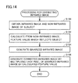
- FIG. 14 A processing procedure in the processing for correcting an infrared image provided by the image processing program in the present embodiment will be described with reference to Fig. 14 .
- Each step shown in Fig. 14 is implemented typically as CPU 10 executes image processing program 16 ( Fig. 2 ).
- CPU 10 obtains an infrared image and a non-infrared image of a subject (step S100).
- image pick-up portion 4 including image pick-up elements in Bayer arrangement as shown in Fig. 6A an infrared image and a non-infrared image can simultaneously be obtained by providing an image pick-up command to image pick-up portion 4.
- image pick-up portion 4 in which image pick-up elements are individually provided as shown in Fig. 6B an infrared image and a non-infrared image are obtained by providing an image pick-up command to each image pick-up element.
- CPU 10 calculates a feature value reflecting an object from the non-infrared image (step S102).
- CPU 10 specifies a flesh-color region by subjecting RGB image 50 representing one example of the non-infrared image to flesh-color detection processing.
- CPU 10 generates binarized infrared image 62 by subjecting infrared image 60 to binarization processing in parallel to the processing in step S102 (step S104).
- CPU 102 generates corrected infrared image 64 by multiplying each pixel of binarized infrared image 62 by the feature value calculated in step S102 (step S106).
- the position determination processing shown in Fig. 5 may be performed by using corrected infrared image 64 generated in step S106.
- an object region expressing an object within an infrared image is specified and a prescribed region is set in accordance with the object region. Since a position of the object included in the infrared image is determined based on brightness and a size of this set prescribed region, one image pick-up portion will suffice, which allows reduction in cost for mount. In addition, since brightness and the size of the prescribed region within the infrared image obtained for each frame is made use of, an amount of operation required for calculating a distance can be reduced and faster processing can be realized.
- a position or movement of an object is detected by using a non-infrared image to remove/reduce information on a substance other than the object from the infrared image.
- a non-infrared image to remove/reduce information on a substance other than the object from the infrared image.
- An image processing program in an embodiment causes a computer to function as image obtaining means for obtaining an infrared image mainly including information of infrared rays from a subject and a non-infrared image mainly including information of light different in wavelength from the infrared rays from the subject and correction means for correcting the infrared image based on a feature value of the non-infrared image.
- the feature value of the non-infrared image may be a feature value which cannot be obtained from the infrared image.
- the non-infrared image may include an RGB image.
- the correction means may specify a flesh-color region of the subject from the RGB image and correct the infrared image based on the flesh-color region.
- the image obtaining means may obtain the infrared image and the non-infrared image from image pick-up elements in Bayer arrangement including an IR filter.
- the correction means may selectively use effective information representing the subject included in the infrared image.
- the correction means may ignore a region of the infrared image other than the region where the subject is present.
- the correction means may extract only the region of the infrared image where the subject is present.
- the correction means may include shape specifying means for specifying a shape of the subject included in the non-infrared image and the infrared image may be corrected based on a feature value in the specified shape.
- the correction means may obtain a feature value by binarizing the non-infrared image.
- the correction means may multiply each pixel value of the infrared image by each pixel value of the binarized non-infrared image.
- the image processing program may further cause the computer to function as reflection means for reflecting the information on the infrared image corrected by the correction means on a yet-to-be-corrected infrared image or the non-infrared image.
- An information processing system in an embodiment includes an image pick-up portion for picking up an image of infrared light from a subject and light different in wavelength from infrared rays from the subject and a processing portion for correcting an infrared image obtained through image pick-up by the image pick-up portion based on a feature value of a non-infrared image obtained through image pick-up by the image pick-up portion.
- An information processing system in an embodiment includes image obtaining means for obtaining an infrared image mainly including information of infrared rays from a subject and a non-infrared image mainly including information of light different in wavelength from the infrared rays from the subject and correction means for correcting the infrared image based on a feature value of the non-infrared image.
- An image processing method in an embodiment includes the steps of obtaining an infrared image mainly including information of infrared rays from a subject and a non-infrared image mainly including information of light different in wavelength from the infrared rays from the subject and correcting the infrared image based on a feature value of the non-infrared image.
Landscapes
- Engineering & Computer Science (AREA)
- Computer Vision & Pattern Recognition (AREA)
- Physics & Mathematics (AREA)
- General Physics & Mathematics (AREA)
- Theoretical Computer Science (AREA)
- Multimedia (AREA)
- Signal Processing (AREA)
- Studio Devices (AREA)
- Length Measuring Devices By Optical Means (AREA)
- Image Processing (AREA)
Abstract
Description
- The present invention relates to an image processing program capable of processing an infrared image, an information processing system, an information processing apparatus, and an image processing method.
- Japanese Patent Laying-Open No.
2005-350010 - The apparatus shown in the prior art document calculates distance data with the use of the stereo infrared cameras and monitors a target based on the calculated distance data. According to this conventional technique, stereo (that is, a plurality of) infrared cameras are required and there is a room for improvement in cost for mounting.
- The object above can be achieved, for example, as follows.
- An image processing program in an embodiment causes a computer to function as image obtaining means for obtaining an infrared image of a subject and position determination means for determining a position of the subject included in the infrared image based on brightness and a size of a prescribed region of the subject within the infrared image.
- In the exemplary embodiment, the position determination means may determine a relative position of the subject with a reference position.
- In the exemplary embodiment, the position determination means may determine the reference position based on an infrared image corresponding to the subject positioned in a reference state.
- In the exemplary embodiment, the position determination means may determine a position of the subject based on the brightness of the prescribed region at the time when the size of the prescribed region satisfies a prescribed condition.
- In the exemplary embodiment, the position determination means may determine a depth position of the subject in a direction of image pick-up by an image pick-up portion which obtains the infrared image, based on the brightness and the size of the prescribed region.
- In the exemplary embodiment, the position determination means may determine the depth position and determine a position on a surface orthogonal to the direction of the subject based on a position of the prescribed region within the infrared image.
- In the exemplary embodiment, the position determination means may include region specifying means for specifying a region of the subject from the infrared image and specifying the prescribed region in accordance with the specified region.
- In the exemplary embodiment, the region specifying means may specify the prescribed region of the subject based on at least a part of a shape which the subject intrinsically has.
- In the exemplary embodiment, the position determination means may determine a position of the subject when the brightness of the prescribed region and the size of the prescribed region satisfy prescribed relation.
- In the exemplary embodiment, the position determination means may determine the position of the subject when change over time in brightness of the prescribed region and change over time in size of the prescribed region maintain the prescribed relation.
- In the exemplary embodiment, the position determination means may determine the position of the subject when magnitude of change over time in brightness of the prescribed region and magnitude of change over time in size of the prescribed region maintain the prescribed relation.
- In the exemplary embodiment, the position determination means may output change over time in position of the subject.
- In the exemplary embodiment, the image obtaining means may obtain an infrared image which is picked up during emission of infrared rays to the subject.
- An information processing system in an embodiment includes an image pick-up portion which picks up an image of infrared light from a subject and a processing portion which determines a position of the subject included in the infrared image based on brightness and a size of a prescribed region of the subject within the infrared image obtained as a result of image pick-up by the image pick-up portion.
- An information processing apparatus in an embodiment includes image obtaining means for obtaining an infrared image of a subject and position determination means for determining a position of the subject included in the infrared image based on brightness and a size of a prescribed region of the subject within the infrared image.
- An image processing method in an embodiment includes the steps of obtaining an infrared image of a subject and determining a position of the subject included in the infrared image based on brightness and a size of a prescribed region of the subject within the infrared image.
- According to the present embodiment, a configuration for determining a position of a subject can be realized with lower cost.
- The foregoing and other objects, features, aspects and advantages of the present invention will become more apparent from the following detailed description of the exemplary embodiments when taken in conjunction with the accompanying drawings.
-
-
Fig. 1 shows an exemplary illustrative non-limiting drawing illustrating an application example of an image processing program in the present embodiment. -
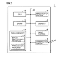
Fig. 2 shows an exemplary illustrative non-limiting drawing illustrating a configuration example of an information processing apparatus in the present embodiment. -
Figs. 3 and4 each show an exemplary illustrative non-limiting drawing illustrating overview of position determination processing performed by the image processing program in the present embodiment. -
Fig. 5 shows an exemplary illustrative non-limiting flowchart illustrating a processing procedure in the position determination processing provided by the image processing program in the present embodiment. -
Figs. 6A and 6B show exemplary illustrative non-limiting drawings illustrating some configuration examples of an image pick-up portion of an information processing apparatus in the present embodiment. -
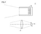
Fig. 7 shows an exemplary illustrative non-limiting drawing illustrating a configuration example of the image pick-up portion incorporating an infrared ray projection function of the information processing apparatus in the present embodiment. -
Fig. 8 shows an exemplary illustrative non-limiting drawing illustrating relation between a distance from the image pick-up portion to an object and brightness of infrared rays detected by the image pick-up portion when an image pick-up condition is constant. -
Figs. 9A and 9B each show an exemplary illustrative non-limiting drawing illustrating relation between brightness of a prescribed region and a size of the prescribed region. -
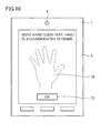
Fig. 10 shows an exemplary illustrative non-limiting drawing illustrating one example of a user interface for calibration provided by the information processing apparatus in the present embodiment. -
Fig. 11 shows an exemplary illustrative non-limiting drawing illustrating one example of processing for calculating an absolute position in the present embodiment. -
Fig. 12 shows an exemplary illustrative non-limiting drawing illustrating one example of processing for correcting an infrared image in the present embodiment. -
Figs. 13A and 13B each show an exemplary illustrative non-limiting drawing illustrating one example of processing for specifying a flesh-color region. -
Fig. 14 shows an exemplary illustrative non-limiting flowchart illustrating a processing procedure in processing for correcting an infrared image provided by the image processing program in the present embodiment. - The present embodiment will be described in detail with reference to the drawings. The same or corresponding elements in the drawings have the same reference characters allotted and description thereof will not be repeated.
- An application example of an image processing program in the present embodiment will initially be described. Referring to
Fig. 1 , the image processing program in the present embodiment is executed in aninformation processing apparatus 1 and a position of a subject is determined by performing processing as will be described later on an image obtained as a result of image pick-up of the subject. In the present embodiment, an infrared image (which may hereinafter be denoted as an "infrared (IR) image") mainly including information of infrared rays from a subject is obtained, and processing is performed on that infrared image. The infrared image herein includes at least any information of infrared rays resulting from reflection by a subject and infrared rays generated by a subject itself. Furthermore, the infrared image should only mainly include infrared information, and an image including visible ray information together with infrared information is not excluded. - In one of application examples, as shown in
Fig. 1 , an image of a part of a body (for example, a hand or a finger) of a user as a subject is picked up and a position of the part of the body of the user is determined every prescribed cycle or for each event. The determined position may be a relative position of a subject with a reference position or an absolute position from information processing apparatus 1 (strictly, an image pick-up portion 4). - A typical example of
information processing apparatus 1 includes not only a portable information processing apparatus (Fig. 1 showing an example of a smartphone) but also a stationary information processing apparatus (for example, a personal computer or a television set) and a camera.Information processing apparatus 1 includes image pick-up portion 4 picking up an image of infrared light from a subject. Image pick-up portion 4 may be able to obtain a non-infrared image in addition to an infrared image. A processing portion performing various types of processing as will be described later and image pick-up portion 4 can also be implemented as independent housings and they can be mounted as an information processing system as being combined with each other. - A non-infrared image means an image mainly including information of light different in wavelength from infrared rays from a subject and typically includes a visible light image mainly including information of visible rays from a subject. The visible light image may be output as an RGB image, a gray-scale image, or a binarized (monochrome) image. An ultraviolet image mainly including information of ultraviolet rays from a subject may be employed as the non-infrared image.
-
Information processing apparatus 1 shown inFig. 1 incorporates adisplay 2 which displays information on a determined position of a subject and a state of execution of an application with the use of the determined position. The determined position may be input as information representing a gesture of a user or may be used for game processing with the determined position being used as it is as an input value. - A configuration example of
information processing apparatus 1 will now be described. Referring toFig. 2 ,information processing apparatus 1 includes, as typical components,display 2, image pick-upportion 4, aninput portion 6, a communication portion 8, a central processing unit (CPU) 10, a dynamic random access memory (DRAM) 12, and aflash memory 14. - Image pick-up
portion 4 receives light from a subject and outputs an image showing the subject. In the present embodiment, image pick-upportion 4 outputs an infrared image of a subject. The infrared image mainly includes information of infrared rays from a subject. In addition, image pick-upportion 4 may output a non-infrared image mainly including information of light different in wavelength from infrared rays from a subject. Namely, image pick-upportion 4 picking up an image of infrared light from the subject and light different in wavelength from infrared rays from the subject may be adopted. -
Display 2 is a device notifying a user of various types of information and implemented by a liquid crystal display (LCD) or an organic electroluminescence (EL) display. -
Input portion 6 is a device accepting an instruction or an operation from a user, and it may be mounted as various buttons or switches provided in a housing ofinformation processing apparatus 1 or may be mounted as a touch panel arranged integrally withdisplay 2. - Communication portion 8 is a device mediating communication with another apparatus and mounted with the use of a mobile communication component such as long term evolution (LTE) or third generation (3G) or a near field communication component such as wireless LAN complying with IEEE 802.1 ln specifications, Bluetooth®, or infrared data association (IRDA).
-
CPU 10 represents one example of processors executing various programs and implements a main portion of the processing portion.DRAM 12 functions as a working memory temporarily holding data necessary forCPU 10 to execute various programs.Flash memory 14 is a storage device holding various types of data in a non-volatile manner, and typically stores animage processing program 16 andvarious application programs 18. These programs are read and developed onDRAM 12 and then executed byCPU 10. - Hardware and software implementing
information processing apparatus 1 are not limited to those shown inFig. 2 . For example, an external server device may have functions ofinformation processing apparatus 1 in the entirety or in part. Namely, instead of a singleinformation processing apparatus 1, an information processing system constituted of a terminal and one or more servers may be employed. In this case, each means in the information processing system is implemented by processing by a processor of the terminal, processing by a processor of the external server device, or cooperative processing by the processor of the terminal and the processor of the external server device. Allocation of processing can be designed as appropriate based on the common general technical knowledge of a person skilled in the art. -
Image processing program 16 executed ininformation processing apparatus 1 is not limited to that provided by a storage medium but may be provided by downloading through a network such as the Internet. - Overview of position determination processing performed by the image processing program in the present embodiment will now be described. The position determination processing in the present embodiment determines a position of a (portion of interest of a) subject based on information of an image showing the subject included in an obtained infrared image. A portion of a subject (i.e. a real substance) of which position is to be determined is hereinafter referred as an "object" and a region corresponding to the "object" within the infrared image is referred to as an "object region".
- Brightness (illumination) and a size of an object region within the infrared image obtained as a result of image pick-up of an object by image pick-up
portion 4 have correlation with factors as below. More specifically, brightness of the object region is in proportion to factors below: - Brightness (illumination/intensity) of infrared rays emitted to a subject;
- A time period of exposure in the image pick-up portion;
- A surface reflectance of an object; and
- 1/(distance from image pick-up
portion 4 to the object)2. - A size of an object region is in inverse proportion to a distance from image pick-up
portion 4 to the object. - The position determination processing in the present embodiment determines, with the use of such physical relationship, a position of an object (a subject) included in an infrared image based on brightness and a size of a prescribed region of the subject within the infrared image. The prescribed region corresponds to a region including at least a part of a region expressing the object (that is, the object region), and can be specified based on at least a part of a shape which the subject (object) intrinsically has.
- In the present embodiment, by using the infrared image mainly including information of infrared rays from the subject, a position can be determined with accuracy higher than in a case of use of a visible light image mainly including information of visible rays from the subject.
- Overview of the position determination processing performed by the image processing program in the present embodiment will be described with reference to
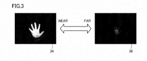
Figs. 3 and4 .Figs. 3 and4 each show an example of an infrared image obtained at the time when a user's hand is defined as an object by way of example. As shown inFig. 3 , when a distance from image pick-upportion 4 to the object is relatively short, an object region within the infrared image is relatively bright (illumination is high) and an area thereof is relatively large (wide). In contrast, when a distance from image pick-upportion 4 to the object is relatively large, the object region within the infrared image is relatively dark (illumination is low) and an area thereof is relatively small (narrow). - Whether the object has moved closer or away is determined based on brightness (illumination/intensity) and a size of the object region which appears in such an infrared image, with a reference position. A method of calculating a distance between image pick-up
portion 4 and an object (a relative distance) with a position of the object (subject) positioned in a reference state (the reference position) being defined as the reference will be described hereinafter as a typical example. -
Fig. 4 is a diagram showing one example of an infrared image picked up at the time when an object is in the reference state. Referring toFig. 4 , a user places his/her hand at a position where the user would use the hand in a normal action and an infrared image is obtained in response to some trigger. This trigger may directly be input by the user, or a trigger may be such that infrared images are repeatedly obtained and subjected to some kind of image processing and a result thereof satisfies a predetermined condition. - When the infrared image in the reference state is obtained, an object region (in the example in
Fig. 4 , a contour of a hand) is specified from the infrared image. Aprescribed region 30 is set in accordance with the specified object region. A representative value (an initial value) for illumination at the reference position is determined based on illumination of each pixel included inprescribed region 30. An average value of illumination of all pixels included inprescribed region 30 can be calculated as the representative value (initial value). In calculation of the representative value, an abnormal value of illumination included inprescribed region 30 may be excluded. - A procedure for obtaining a reference position and initial information relating thereto (for example, a representative value), which includes the processing as shown in
Fig. 4 , will hereinafter also be referred to as "calibration". - For example, a distance from image pick-up
portion 4 to an object inprescribed region 30 within aninfrared image 32 shown inFig. 4 is set as "1". Here, it is assumed that a calculated average value of brightness is "100" and a size of prescribedregion 30 is "100×100" pixels. - An infrared image 34 (near) shown in
Fig. 3 is an infrared image obtained at the time when a hand is placed at a position at a distance "0.7" time as large as a distance from image pick-upportion 4 to the object at the time of image pick-up of infrared image 32 (Fig. 4 ), and here, a size of prescribedregion 30 was calculated as "160×160" pixels and an average value of brightness was calculated as "204". - An infrared image 36 (far) shown in
Fig. 3 is an infrared image obtained at the time when a hand is placed at a position at a distance "2.0" times as large as a distance from image pick-upportion 4 to the object at the time of image pick-up of infrared image 32 (Fig. 4 ), and here, a size of prescribedregion 30 was calculated as "60x60" pixels and an average value of brightness was calculated as "25". - A processing procedure in the position determination processing provided by the image processing program in the present embodiment will be described with reference to
Fig. 5 . Each step shown inFig. 5 is implemented typically asCPU 10 executes image processing program 16 (Fig. 2 ). - Initially, calibration shown in steps S2 to S10 is carried out. Specifically,
CPU 10 obtains an infrared image of a subject (step S2). Here, it is assumed that an object (a subject) of which position is to be determined is in the reference state. The infrared image is obtained asCPU 10 provides a command to image pick-up portion (Fig. 2 ). - In succession,
CPU 10 specifies an object region (a region of the subject) from the infrared image (step S4) and sets a prescribed region in accordance with the specified object region (step S6).CPU 10 calculates a representative value for illumination based on illumination of each pixel included in the specified prescribed region (step S8). This representative value for illumination is stored as an initial value for illumination at the reference position. Then,CPU 10 has the calculated representative value for illumination (brightness of the prescribed region) and the size of the prescribed region stored as results of calibration (step S10). - In calibration, brightness and a size of a prescribed region corresponding to a position of the object (subject) in the reference state (reference position) are determined, and a relative position of the object is successively determined with the position in this reference state being defined as the reference. Namely, in accordance with a procedure as below,
CPU 10 determines a position of the subject included in the infrared image based on brightness and a size of the prescribed region within the infrared image. - Specifically,
CPU 10 obtains a new infrared image (step S12). Then,CPU 10 newly specifies an object region (a region of the subject) from the infrared image (step S14) and sets a prescribed region in accordance with the specified object region (step S16). In succession,CPU 10 calculates a representative value for illumination of the prescribed region (brightness of the prescribed region) based on illumination of each pixel included in the prescribed region specified in step S16 (step S18) and determines whether or not calculated brightness and the size of the prescribed region satisfy a prescribed condition (step S20). - When brightness and the size of the prescribed region satisfy the prescribed condition (YES in step S20),
CPU 10 determines a position of the object from calculated brightness of the prescribed region based on brightness of the prescribed region obtained in calibration (step S22). In succession,CPU 10 performs predetermined post-processing in accordance with the determined position of the object (step S24). Namely, a position determination function ofinformation processing apparatus 1 determines a position of an object (subject) when brightness of a prescribed region and a size of the prescribed region satisfy prescribed relation. - When brightness and the size of the prescribed region do not satisfy the prescribed condition (NO in step S20),
CPU 10 performs error processing (step S26). -
CPU 10 determines whether or not end of the position determination processing has been indicated (step S28). When end of the position determination processing has not been indicated (NO in step S28), processing in step S12 or later is repeated. In contrast, when end of the position determination processing has been indicated (YES in step S28), the position determination processing ends. - Processing for obtaining an infrared image and a mechanism used therefor will now be described.
- Some configuration examples of image pick-up
portion 4 ofinformation processing apparatus 1 in the present embodiment will be described with reference toFigs. 6A and 6B. Fig. 6A shows a configuration example including image pick-up elements in Bayer arrangement including an IR filter andFig. 6B is a diagram showing a configuration example in which image pick-up elements generating an infrared image (IR image) and a non-infrared image (RGB image) respectively are individually provided. - The image pick-up elements shown in
Fig. 6A are image pick-up elements in which one G filter of four color filters (R + Gx2 + B) has been replaced with an IR filter in general image pick-up elements in Bayer arrangement. The IR filter has characteristics to allow passage of infrared rays and infrared rays from a subject are incident on a detection element associated with the IR filter, which detects illumination thereof. Detection elements associated with R, G, and B filters, respectively, detect illumination of visible rays from the subject. An IR image is generated based on information from the detection element associated with the IR filter and an RGB image is generated based on information from the detection elements associated with the R, G, and B filters, respectively. - Namely, in the configuration example shown in
Fig. 6A ,information processing apparatus 1 obtains an infrared image and a non-infrared image from the image pick-up elements in Bayer arrangement including the IR filter. - On the other hand, in the configuration example shown in
Fig. 6B , a dual-eye optical system is employed. Namely, light reflected from the subject is guided to image pick-upelements lenses element 43 and a not-shown color (RGB) filter is associated with image pick-upelement 44. Thus, image pick-upelement 43 generates an infrared image (IR image) and image pick-upelement 44 generates a non-infrared image (RGB image). - A configuration in which an independent image pick-up element is arranged for each of R, G, and B may be adopted as another configuration example. In this case, four image pick-up elements in total of R, G, B, and IR are arranged. A plurality of image pick-up elements may be arranged with a lens being common thereto.
- By adopting any configuration described above, an infrared image and a non-infrared image (typically, an RGB image) can simultaneously be obtained from the same subject.
- An infrared ray projection function will now be described. An infrared image is mainly generated from information of infrared rays from a subject, however, an amount of infrared rays incident on the subject is not sufficient in many cases in a general environment of use. Therefore, an infrared ray projection function is preferably incorporated as a function of image pick-up
portion 4. Namely, as a function ofinformation processing apparatus 1 to obtain an image, an infrared image which is picked up during emission of infrared rays to a subject is preferably obtained. - A configuration example of image pick-up
portion 4 incorporating an infrared ray projection function ofinformation processing apparatus 1 in the present embodiment will be described with reference toFig. 7 . In addition tolens 41 guiding light from the subject to image pick-upelement 43, anemission portion 45 emitting infrared rays to the subject is provided.Emission portion 45 has a portion generating infrared rays, such as an infrared LED or an infrared lamp, and emits generated infrared rays to the subject. The timing of exposure by image pick-upelement 43 and the timing of light emission byemission portion 45 are in synchronization with each other. - Since an image pick-up condition can be stabilized by incorporating such a ray projection function, accuracy in determination of a position of an object can be enhanced.
- A function similar to common strobe light in addition to infrared rays may be added to
emission portion 45. Namely,emission portion 45 may be configured to simultaneously emit infrared rays and visible rays to the subject. -
Fig. 8 shows relation between a distance from image pick-upportion 4 to an object and brightness of infrared rays detected by image pick-upportion 4 when an image pick-up condition is constant. A distance and brightness are expressed in an arbitrary unit. As described above, since brightness of an object region within an infrared image is in inverse proportion to a square of (a distance from image pick-upportion 4 to the object), brightness of infrared rays detected by image pick-upportion 4 gradually decreases as the object is away from image pick-upportion 4 as shown inFig. 8 . Change in distance corresponding to change per unit of detected brightness is greater as the distance is greater, which means that sensitivity in calculation of a distance (that is, resolution) lowers as the object is away from image pick-upportion 4. In a characteristic example shown inFig. 8 , resolution is approximately 0.5 when a distance is less than 20, and resolution is approximately 1 when a distance is from 20 to 40. When a distance is 40 or more, however, resolution of only approximately 2.5 is obtained. - Since a range of brightness of infrared rays detectable by image pick-up
portion 4 is restricted to a finite gray-scale value (typically, from 0 to 255 levels of gray), a time period of exposure by image pick-up portion 4 (a shutter speed) as well as brightness of infrared rays emitted fromemission portion 45 and/or a time period of emission are preferably varied depending on a distance from image pick-upportion 4 to the object. For example, a known autoexposure (AE) function can be used. - More specifically, the function of information processing apparatus 1 (CPU 10) to obtain an image provides a control command to
emission portion 45 so as to emit more intense infrared rays as a distance to the subject is longer. Namely, when a distance from image pick-upportion 4 to the object is relatively long, brightness of infrared rays incident on image pick-upportion 4 is relatively low and hence more intense infrared rays are emitted. - In addition, the function of information processing apparatus 1 (CPU 10) to obtain an image provides a control command such that a time period of exposure by the image pick-up portion for obtaining an infrared image is longer as a distance to the subject is longer. Namely, when a distance from image pick-up
portion 4 to the object is relatively long, brightness of infrared rays incident on image pick-upportion 4 is relatively low and hence a time period of exposure by image pick-upportion 4 is controlled such that infrared rays are incident for a longer period of time. - A distance from image pick-up
portion 4 to an object can be determined with the use of a result of determination of a distance of an object in the past. Typically, a distance determined in an immediately preceding operation cycle may be used to determine an image pick-up condition (a time period of emission of infrared rays/emission intensity and a time period of exposure). - Any of a rolling shutter technique and a global shutter technique may be employed as a method of exposure by image pick-up
portion 4. The rolling shutter technique is suitable for a portable information processing apparatus, because it adopts progressive scanning and power consumption is relatively low. On the other hand, according to the global shutter technique, since a time period of exposure is relatively short, image pick-up of a vigorously moving subject can more appropriately be achieved. - A method of specifying an object region can include, for example, a method of extracting a geometry from a feature point (for example, an edge point at which illumination significantly varies) in distribution of illumination within an infrared image, a method of extracting a region or a geometry based on other feature values included in an infrared image, and a method of extraction based on at least a part of a shape which a subject (object) intrinsically has.
- In the examples shown in
Figs. 3 and4 described above, a hand (palm) is defined as the object. Therefore, an object region can be specified by searching for a specific shape of the hand (for example, portions showing five fingers). Namely, a contour (or a geometry) of the hand can be specified based on a feature value within an infrared image. - A prescribed region is set in accordance with an object region corresponding to the specified hand. The prescribed region is not limited to a rectangular shape, and a geometry indicating a feature value (an object region) may be employed as it is. When a shape of the object has already been known, a shape similar to that already-known shape may be employed. Alternatively, a prescribed region may be set so as to include a region outside the object region.
- In the examples shown in
Figs. 3 and4 , a region corresponding to the palm of a user is preferably set as prescribedregion 30. Namely, fingers of the hand of the user are preferably excluded from prescribedregion 30. Since fingers of the hand are relatively great in motion over time and calculated illumination is unstable, they are preferably excluded. Brightness of infrared rays reflected from the subject is dependent on a reflectance at the surface of the subject. Movement of fingers of the hand which leads to relatively significant change in reflectance is also a cause of unsuitableness of the fingers for use in position determination. Therefore, in order to enhance accuracy in position determination, such a vigorously moving portion is preferably excluded. - In the position determination processing in the present embodiment, basically, a position of an object is determined based on a representative value calculated from illumination of a pixel included in a prescribed region. Here, there is also a case that a substance other than the object of interest has been photographed in an infrared image, and there is also a possibility that a position is erroneously determined due to a partial image caused by such a substance. Therefore, such erroneous position determination is avoided by using conditions as below. All or some of the conditions below may be employed.
- One condition is such that whether or not brightness of the prescribed region and a size of the prescribed region satisfy prescribed relation is determined, and when the prescribed relation is satisfied, a position of a subject may be determined based on brightness of the prescribed region.
- As described above, brightness of an object region is in inverse proportion to a square of a distance from image pick-up
portion 4 to an object, and a size of the object region is in inverse proportion to the distance from image pick-upportion 4 to the object. Therefore, essentially, brightness of the prescribed region and the size of the prescribed region set in accordance with the object region maintain prescribed relation. -
Figs. 9A and 9B show relation between brightness of the prescribed region and a size of the prescribed region.Fig. 9A conceptually shows a result in a case that a state of an object moving away from image pick-upportion 4 could appropriately be detected, andFig. 9B conceptually shows a result in a case that a state that the object moves away from image pick-upportion 4 could not appropriately be detected. - As shown in
Fig. 9A , when the object moves away from image pick-upportion 4, brightness of the prescribed region and a size of the prescribed region both decrease. On the other hand, when the object comes closer to image pick-upportion 4, brightness of the prescribed region and the size of the prescribed region both increase. When some cause for error is present in an infrared image, as shown inFig. 9B , change different from inherent change is detected. - Whether or not appropriate detection has successively been achieved is preferably determined by making use of such relation between brightness of the prescribed region and the size of the prescribed region.
- More specifically, whether or not change over time in brightness of the prescribed region and change over time in size of the prescribed region maintain prescribed relation may be determined, and when the prescribed relation is maintained, a position of an object may be determined. Namely, whether or not a direction of change (increase/decrease) in brightness of the prescribed region and change over time (increase/decrease) in size of the prescribed region match with each other may be determined, and when they match, a position of an object is calculated assuming that proper detection has been achieved. In other words, whether or not appropriate detection has successively been achieved can be determined based on match/unmatch in sign (a direction of change) between change over time in brightness of the prescribed region and change over time in size of the prescribed region.
- Alternatively, whether or not magnitude in change over time in luminance of the prescribed region and magnitude in change over time in size of the prescribed region maintain prescribed relation may be determined, and when the prescribed relation is maintained, a position of an object may be determined. Namely, whether or not a ratio between an amount of change per unit time (increment/decrement) in brightness of the prescribed region and an amount of change per unit time (increment/decrement) in size of the prescribed region is within a prescribed range is determined, and when the ratio is within the prescribed range, a position of an object is calculated assuming that appropriate detection has been achieved. Namely, whether or not appropriate detection has successively been achieved can be determined based on a state of deviation in value between the amount of change per unit time in brightness of the prescribed region and the amount of change per unit time in size of the prescribed region.
- Instead of/in addition to the method paying attention to relative relation between brightness of the prescribed region and the size of the prescribed region as described above, whether or not a size itself of the prescribed region satisfies a prescribed condition may be determined, and when the prescribed condition is satisfied, a position of a subject may be determined based on brightness of the prescribed region.
- More specifically, whether or not appropriate detection has successively been achieved can be determined by determining whether a detected size of the prescribed region is excessively larger or smaller than the size of the prescribed region obtained in calibration (a reference value). Namely, whether or not a ratio or a difference of the detected size of the prescribed region to or from the size of the prescribed region obtained in calibration (a reference value) is within a prescribed range is determined, and only when the ratio or the difference is within the prescribed range, a position of the object may be calculated assuming that appropriate detection has been achieved.
- Brightness of the prescribed region is in inverse proportion to a square of a distance from image pick-up
portion 4 to an object. Therefore, when brightness of the prescribed region is calculated as B at some time point, a distance L between image pick-upportion 4 and the object at that time can be expressed as below.
- L0 represents a distance between image pick-up
portion 4 and the object obtained in calibration and B0 represents brightness of the prescribed region obtained in calibration. - With a condition of L0 = 1 being set, a relative distance between image pick-up
portion 4 and the object can be calculated by using brightness B0 of the prescribed region obtained in calibration. This relative distance represents a depth position in a direction of image pick-up by image pick-up portion 4 (a camera direction: a z direction). A position within an infrared image where the prescribed region is present represents a position (an x coordinate and a y coordinate) on a plane orthogonal to the direction of image pick-up by image pick-upportion 4. Thus, in the present embodiment, a depth position of the object in the direction of image pick-up by image pick-upportion 4 which obtains an infrared image is determined based on brightness and a size of the prescribed region. Namely, a depth position is determined and a position on the plane orthogonal to the direction of image pick-up of the object is determined based on a position of the prescribed region within the infrared image. - Finally, an x coordinate, a y coordinate, and a z coordinate of the object defined in a coordinate system with a point of view of image pick-up
portion 4 being defined as the reference are output every operation cycle. - As described above,
information processing apparatus 1 calculates a three-dimensional coordinate of an object every operation cycle and obtains a temporal behavior of the object from these chronologically output three-dimensional coordinates. Namely,information processing apparatus 1 outputs change over time in position of the object. With such change over time in position, a gesture made by a user can be determined or various types of game processing can progress. - Calibration should be carried out with the object (subject) being set to the reference state. The reference state may be any state, however, when the object is too close to or far from image pick-up
portion 4, accuracy in position determination lowers. Therefore, calibration is preferably carried out at an intermediate point in a range where the object can move. Therefore, a user interface as supporting such calibration may be provided. - One example of a user interface for calibration provided by
information processing apparatus 1 in the present embodiment will be described with reference toFig. 10 . Referring toFig. 10 , aguide 70 for positioning a subject to the reference state is displayed ondisplay 2 ofinformation processing apparatus 1 and the user adjusts positional relation between the user himself/herself and/or his/her hand and image pick-upportion 4 such that a hand of which image is picked up is accommodated inguide 70. When the user's hand is accommodated inguide 70, the user operates anOK button 72 displayed ondisplay 2 with the other hand so that an infrared image for calibration is obtained and calibration is performed. - By displaying such a guide, calibration can more appropriately and simply be carried out.
- A processing example in which a relative position of an object is successively determined with a position in the reference state being defined as the reference has been described above. If an absolute position (an absolute distance) in the reference state could be obtained, not a relative position but a pseudo absolute position can be calculated.
- A method of using image pick-up
portion 4 ofinformation processing apparatus 1 to obtain in advance relation between a size and an absolute position of an object region which appears in an infrared image and using this relation is available as one technique for obtaining an absolute position (an absolute distance) in the reference state. Specifically, relation between a size of the object region and an absolute distance from image pick-upportion 4 can be defined based on an infrared image obtained by using image pick-upportion 4 to pick up images of a sample having an already-known size in advance arranged at a plurality of positions. An absolute distance at the time of image pick-up can be determined by picking up an image of a sample (for example, a stylus attached to information processing apparatus 1) of which size has already been known in calibration and evaluating a size within the infrared image of the sample of which image has been picked up. - When a user's hand is adopted as the object, an average size is known in advance. Therefore, a pseudo absolute distance at the time of calibration may be determined based on the average value.
- One example of processing for calculating an absolute position in the present embodiment will be described with reference to
Fig. 11 . Relation between a size and an absolute position of the object region which appears in an infrared image which has been obtained in advance may be referred to by specifying a contour of the hand from a feature value within the infrared image and calculating a size of the hand, and then a position (a depth position) where the hand is present may be calculated. - In the processing for determining a position of an object described above, an object region within an infrared image is specified and a prescribed region is set (steps S4, S6, S14, and S16 in
Fig. 5 ). In such processing, an infrared image including only the object is preferably obtained. When a substance which emits infrared rays is present in the background of the object at the time of image pick-up of the object, however, the infrared rays from such a substance are introduced as noise in the infrared image. In such a case, preferably, the infrared image is subjected to some correction (pre-processing) and then the object region is specified. - Processing in a case that a non-infrared image is used will be described below as processing for correcting such an infrared image. Namely,
information processing apparatus 1 in the present embodiment has an image obtaining function to obtain an infrared image mainly including information of infrared rays from an object (subject) and a non-infrared image mainly including information of light different in wavelength from the infrared rays from the object (subject) and a correction function to correct the infrared image based on a feature value of the non-infrared image. - One example of the processing for correcting the infrared image in the present embodiment will be described with reference to
Fig. 12 . When aninfrared image 60 is obtained through image pick-up of an object, anRGB image 50 representing one example of a non-infrared image is obtained. As will be described later, such processing as superimposition of images ofRGB image 50 andinfrared image 60 is required. Therefore, these two images are preferably obtained by using image pick-up elements in Bayer arrangement including an IR filter as shown inFig. 6A described above. Though a dual-eye configuration as shown inFig. 6B may be adopted, in this case, correction in accordance with a parallax present between optical systems is required. - The non-infrared image is not limited to the RGB image, and an ultraviolet image may be employed or a gray image (a monochromatic image) with attention being paid only to any color of R, G, and B may be employed.
- As shown in
RGB image 50 andinfrared image 60 inFig. 12 , luminance information of an object which can be obtained is different depending on a difference in detected wavelength. With the use of such difference in obtained luminance information, correction as allowing extraction only of information on the object is made. - Initially, a feature value reflecting the object is calculated from the non-infrared image. When
RGB image 50 is defined as the non-infrared image and the user's hand is defined as the object, for example, flesh-color detection processing can be employed. Namely, a flesh-color region included inRGB image 50 is specified. Aresult image 52 shows a result afterRGB image 50 has been subjected to flesh-color detection.Result image 52 results from conversion of a pixel determined to be in flesh color into "1" (white) and converting pixels other than that into "0" (black). Namely, in the processing for correcting the infrared image, a feature value is obtained by binarizing the non-infrared image. - One example of processing for specifying a flesh-color region will be described with reference to
Fig. 13 . In order to specify a flesh-color region, a color coordinate system of the RGB image is converted from the RGB coordinate system (Fig. 13A ) to a YUV coordinate system (Fig. 13B ). Then, an image present in a domain (a space) on the color coordinate system which can be regarded as having a "flesh color" defined in advance is extracted from a YUV image converted to the YUV coordinate system. Use of the YUV coordinate system allows more accurate determination of the "flesh color". - Thus, the correction processing in
information processing apparatus 1 includes processing for specifying a flesh-color region of the object (subject) from the RGB image and correctinginfrared image 60 based on the flesh-color region. - Referring again to
Fig. 12 ,infrared image 60 is also subjected to binarization processing by using prescribed brightness as a threshold value, to thereby generate a binarizedinfrared image 62. Finally, a correctedinfrared image 64 is generated by calculating a product ofresult image 52 and binarizedinfrared image 62 for each corresponding pixel. Namely, in the correction processing, processing for multiplying each pixel value of the infrared image by each pixel value of the binarized non-infrared image (result image 52) is performed. This processing means output as an effective pixel, of only such a pixel of which corresponding pixel withinresult image 52 has been converted into "1" (flesh-color region), among pixels constituting binarizedinfrared image 62. -
Infrared image 60 does not necessarily have to be binarized, andinfrared image 60 can be corrected by usingresult image 52 as one type of mask image and multiplying each pixel value ofinfrared image 60 by the result image. - As described above,
information processing apparatus 1 correctsinfrared image 60 based on a feature value (a flesh-color region in the example shown inFig. 12 ) of a non-infrared image (RGB image 50). The feature value of the non-infrared image is basically a feature value which cannot be obtained from the infrared image. - Processing for correcting
infrared image 60 includes processing for ignoring a region other than the region ofinfrared image 60 where the object (subject) is present. In other words, means for correctinginfrared image 60 includes processing for extracting only a region ofinfrared image 60 where the object (subject) is present. A series of correction processes means that a region in an image where an object is present is specified from a non-infrared image (RGB image 50) and effective information representing the object (subject) included ininfrared image 60 is selectively used in accordance with the specified region. Thus, by selectively using effective information representing the object (subject) included ininfrared image 60, an object region within the infrared image can more accurately be specified. - Processing for specifying an object region may further be performed by searching for a specific shape of the object by using
RGB image 50 and/or resultimage 52 shown inFig. 12 . Namely, a position of a contour (or a geometry) of a hand or a finger may be specified from a feature value within the image as described above. By further performing shape specifying processing for specifying a shape of an object (subject) included in such a non-infrared image (RGB image 50 and/or result image 52), a component introduced in the non-infrared image (light from lighting in the background inRGB image 50 inFig. 12 ), which can be noise, can be removed. - By further adding such shape specifying processing, effective information representing the object (subject) included in
infrared image 60 can more accurately be selected and the object region within the infrared image can more accurately be specified. Namely, the correction processing ofinformation processing apparatus 1 includes the shape specifying processing for specifying a shape of the subject included in the non-infrared image (RGB image 50 and/or result image 52), so thatinfrared image 60 is corrected based on a feature value in the specified shape. - Various types of processing may be performed by using corrected
infrared image 64 and subjecting yet-to-be-correctedinfrared image 60 and/orRGB image 50 to different correction. For example, an object region may be specified from correctedinfrared image 64, and only information on the object may be extracted by using an image (information) of the region withininfrared image 60 orRGB image 50 corresponding to the specified object region. Thus, such a function as reflecting information on the infrared image corrected in the correction processing on a yet-to-be-corrected infrared image or non-infrared image may also be incorporated ininformation processing apparatus 1. - A processing procedure in the processing for correcting an infrared image provided by the image processing program in the present embodiment will be described with reference to
Fig. 14 . Each step shown inFig. 14 is implemented typically asCPU 10 executes image processing program 16 (Fig. 2 ). - Initially,
CPU 10 obtains an infrared image and a non-infrared image of a subject (step S100). Here, when image pick-upportion 4 including image pick-up elements in Bayer arrangement as shown inFig. 6A is employed, an infrared image and a non-infrared image can simultaneously be obtained by providing an image pick-up command to image pick-upportion 4. In contrast, when image pick-upportion 4 in which image pick-up elements are individually provided as shown inFig. 6B is employed, an infrared image and a non-infrared image are obtained by providing an image pick-up command to each image pick-up element. - In succession,
CPU 10 calculates a feature value reflecting an object from the non-infrared image (step S102). Typically,CPU 10 specifies a flesh-color region by subjectingRGB image 50 representing one example of the non-infrared image to flesh-color detection processing.CPU 10 generates binarizedinfrared image 62 by subjectinginfrared image 60 to binarization processing in parallel to the processing in step S102 (step S104). - Then, CPU 102 generates corrected
infrared image 64 by multiplying each pixel of binarizedinfrared image 62 by the feature value calculated in step S102 (step S106). The position determination processing shown inFig. 5 may be performed by using correctedinfrared image 64 generated in step S106. - In the present embodiment, an object region expressing an object within an infrared image is specified and a prescribed region is set in accordance with the object region. Since a position of the object included in the infrared image is determined based on brightness and a size of this set prescribed region, one image pick-up portion will suffice, which allows reduction in cost for mount. In addition, since brightness and the size of the prescribed region within the infrared image obtained for each frame is made use of, an amount of operation required for calculating a distance can be reduced and faster processing can be realized.
- In the present embodiment, a position or movement of an object is detected by using a non-infrared image to remove/reduce information on a substance other than the object from the infrared image. Thus, erroneous determination of a position of the object due to information on the substance other than the object can be suppressed.
- The present specification includes an embodiment as below.
- An image processing program in an embodiment causes a computer to function as image obtaining means for obtaining an infrared image mainly including information of infrared rays from a subject and a non-infrared image mainly including information of light different in wavelength from the infrared rays from the subject and correction means for correcting the infrared image based on a feature value of the non-infrared image.
- The feature value of the non-infrared image may be a feature value which cannot be obtained from the infrared image.
- The non-infrared image may include an RGB image.
- The correction means may specify a flesh-color region of the subject from the RGB image and correct the infrared image based on the flesh-color region.
- The image obtaining means may obtain the infrared image and the non-infrared image from image pick-up elements in Bayer arrangement including an IR filter.
- The correction means may selectively use effective information representing the subject included in the infrared image.
- The correction means may ignore a region of the infrared image other than the region where the subject is present.
- The correction means may extract only the region of the infrared image where the subject is present.
- The correction means may include shape specifying means for specifying a shape of the subject included in the non-infrared image and the infrared image may be corrected based on a feature value in the specified shape.
- The correction means may obtain a feature value by binarizing the non-infrared image.
- The correction means may multiply each pixel value of the infrared image by each pixel value of the binarized non-infrared image.
- The image processing program may further cause the computer to function as reflection means for reflecting the information on the infrared image corrected by the correction means on a yet-to-be-corrected infrared image or the non-infrared image.
- An information processing system in an embodiment includes an image pick-up portion for picking up an image of infrared light from a subject and light different in wavelength from infrared rays from the subject and a processing portion for correcting an infrared image obtained through image pick-up by the image pick-up portion based on a feature value of a non-infrared image obtained through image pick-up by the image pick-up portion.
- An information processing system in an embodiment includes image obtaining means for obtaining an infrared image mainly including information of infrared rays from a subject and a non-infrared image mainly including information of light different in wavelength from the infrared rays from the subject and correction means for correcting the infrared image based on a feature value of the non-infrared image.
- An image processing method in an embodiment includes the steps of obtaining an infrared image mainly including information of infrared rays from a subject and a non-infrared image mainly including information of light different in wavelength from the infrared rays from the subject and correcting the infrared image based on a feature value of the non-infrared image.
- While certain example systems, methods, devices, and apparatuses have been described herein, it is to be understood that the appended claims are not to be limited to the systems, methods, devices, and apparatuses disclosed, but on the contrary, are intended to cover various modifications and equivalent arrangements included within the spirit and scope of the appended claims.
Claims (15)
- An image processing program (16) causing a computer (1) to function as:image obtaining means (S2, S 12) for obtaining an infrared image of a subject; andposition determination means (S4 to S10, S 14 to S28) for determining a position of the subject included in the infrared image based on brightness and a size of a prescribed region of the subject within the infrared image.
- The image processing program according to claim 1, wherein
the position determination means determines a relative position of the subject with a reference position. - The image processing program according to claim 2, wherein
the position determination means determines the reference position based on an infrared image corresponding to the subject positioned in a reference state. - The image processing program according to any one of claims 1 to 3, wherein
the position determination means determines a position of the subject based on the brightness of the prescribed region when the size of the prescribed region satisfies a prescribed condition. - The image processing program according to any one of claims 1 to 4, wherein
the position determination means determines a depth position of the subject in a direction of image pick-up by an image pick-up portion which obtains the infrared image, based on the brightness and the size of the prescribed region. - The image processing program according to claim 5, wherein
the position determination means determines the depth position and determines a position on a surface orthogonal to the direction of image pick-up of the subject based on a position of the prescribed region within the infrared image. - The image processing program according to any one of claims 1 to 6, wherein
the position determination means includes region specifying means for specifying a region of the subject from the infrared image and specifying the prescribed region in accordance with the specified region. - The image processing program according to claim 7, wherein
the region specifying means specifies the prescribed region of the subject based on at least a part of a shape which the subject intrinsically has. - The image processing program according to any one of claims 1 to 8, wherein
the position determination means determines a position of the subject when the brightness of the prescribed region and the size of the prescribed region satisfy prescribed relation. - The image processing program according to claim 9, wherein
the position determination means determines the position of the subject when change over time in brightness of the prescribed region and change over time in size of the prescribed region maintain the prescribed relation. - The image processing program according to claim 9, wherein
the position determination means determines the position of the subject when magnitude of change over time in brightness of the prescribed region and magnitude of change over time in size of the prescribed region maintain the prescribed relation. - The image processing program according to any one of claims 1 to 11, wherein
the position determination means outputs change over time in position of the subject. - The image processing program according to any one of claims 1 to 12, wherein
the image obtaining means obtains an infrared image which is picked up during emission of infrared rays to the subject. - An information processing system, comprising:an image pick-up portion (4) for picking up an image of infrared light from a subject; anda processing portion (10, 12, 14) for determining a position of the subject included in the infrared image based on brightness and a size of a prescribed region of the subject within the infrared image obtained as a result of image pick-up by the image pick-up portion.
- An information processing method, comprising the steps of:obtaining an infrared image of a subject (S2, S12); anddetermining a position of the subject included in the infrared image based on brightness and a size of a prescribed region of the subject within the infrared image (S4 to S10, S 14 to S28).
Applications Claiming Priority (2)
| Application Number | Priority Date | Filing Date | Title |
|---|---|---|---|
| JP2014178055A JP6386837B2 (en) | 2014-09-02 | 2014-09-02 | Image processing program, information processing system, information processing apparatus, and image processing method |
| JP2014178056A JP6368593B2 (en) | 2014-09-02 | 2014-09-02 | Image processing program, information processing system, and image processing method |
Publications (3)
| Publication Number | Publication Date |
|---|---|
| EP2993645A2 true EP2993645A2 (en) | 2016-03-09 |
| EP2993645A3 EP2993645A3 (en) | 2016-05-18 |
| EP2993645B1 EP2993645B1 (en) | 2019-05-08 |
Family
ID=53800819
Family Applications (1)
| Application Number | Title | Priority Date | Filing Date |
|---|---|---|---|
| EP15176430.5A Active EP2993645B1 (en) | 2014-09-02 | 2015-07-13 | Image processing program, information processing system, information processing apparatus, and image processing method |
Country Status (2)
| Country | Link |
|---|---|
| US (1) | US10348983B2 (en) |
| EP (1) | EP2993645B1 (en) |
Families Citing this family (8)
| Publication number | Priority date | Publication date | Assignee | Title |
|---|---|---|---|---|
| US9804667B2 (en) * | 2015-02-10 | 2017-10-31 | Nintendo Co., Ltd. | Electronic apparatus |
| JP6647956B2 (en) * | 2016-04-28 | 2020-02-14 | 任天堂株式会社 | Information processing system, image processing apparatus, information processing program, and information processing method |
| CN111226094A (en) * | 2017-10-24 | 2020-06-02 | 索尼公司 | Information processing device, information processing method, program, and moving object |
| US11644845B2 (en) * | 2019-05-02 | 2023-05-09 | Crown Equipment Corporation | Industrial vehicle with feature-based localization and navigation |
| US12284452B2 (en) | 2019-11-27 | 2025-04-22 | Panasonic Intellectual Property Management Co., Ltd. | Infrared processing system, infrared sensor system, infrared processing method, and program |
| CN111265863B (en) * | 2020-01-17 | 2022-05-24 | 腾讯科技(深圳)有限公司 | Target object position correction method, device, equipment and medium |
| EP4198570A4 (en) * | 2020-08-17 | 2024-01-17 | Sony Group Corporation | Information processing device, information processing method, and information processing program |
| US12671781B2 (en) * | 2023-09-20 | 2026-06-30 | Cista System Corp. | Color noise reduction based on guided filter using luminance information |
Citations (1)
| Publication number | Priority date | Publication date | Assignee | Title |
|---|---|---|---|---|
| JP2005350010A (en) | 2004-06-14 | 2005-12-22 | Fuji Heavy Ind Ltd | Stereo external vehicle monitoring device |
Family Cites Families (49)
| Publication number | Priority date | Publication date | Assignee | Title |
|---|---|---|---|---|
| JP4267171B2 (en) | 1999-05-10 | 2009-05-27 | 本田技研工業株式会社 | Pedestrian detection device |
| JP3756452B2 (en) * | 2002-01-18 | 2006-03-15 | 本田技研工業株式会社 | Infrared image processing device |
| WO2003071410A2 (en) * | 2002-02-15 | 2003-08-28 | Canesta, Inc. | Gesture recognition system using depth perceptive sensors |
| US20040063480A1 (en) * | 2002-09-30 | 2004-04-01 | Xiaoling Wang | Apparatus and a method for more realistic interactive video games on computers or similar devices |
| KR100850460B1 (en) * | 2002-10-10 | 2008-08-07 | 삼성테크윈 주식회사 | How to improve face image in digital camera |
| JP2005037758A (en) * | 2003-07-17 | 2005-02-10 | T S Ink:Kk | Digital theremin |
| JP3903968B2 (en) * | 2003-07-30 | 2007-04-11 | 日産自動車株式会社 | Non-contact information input device |
| US20100013615A1 (en) * | 2004-03-31 | 2010-01-21 | Carnegie Mellon University | Obstacle detection having enhanced classification |
| US7308112B2 (en) * | 2004-05-14 | 2007-12-11 | Honda Motor Co., Ltd. | Sign based human-machine interaction |
| JP4701961B2 (en) | 2005-09-26 | 2011-06-15 | トヨタ自動車株式会社 | Pedestrian detection device |
| JP4732985B2 (en) | 2006-09-05 | 2011-07-27 | トヨタ自動車株式会社 | Image processing device |
| JP4263737B2 (en) * | 2006-11-09 | 2009-05-13 | トヨタ自動車株式会社 | Pedestrian detection device |
| US8116518B2 (en) * | 2007-02-15 | 2012-02-14 | Qualcomm Incorporated | Enhanced input using flashing electromagnetic radiation |
| JP2009010669A (en) | 2007-06-28 | 2009-01-15 | Sony Corp | Image processing apparatus, imaging apparatus, image processing method, and program |
| JP5022868B2 (en) | 2007-11-16 | 2012-09-12 | キヤノン株式会社 | Information processing apparatus and information processing method |
| JP2009232351A (en) | 2008-03-25 | 2009-10-08 | Seiko Epson Corp | Imaging device and color filter array |
| US9740293B2 (en) * | 2009-04-02 | 2017-08-22 | Oblong Industries, Inc. | Operating environment with gestural control and multiple client devices, displays, and users |
| JP2010022700A (en) | 2008-07-23 | 2010-02-04 | Fujifilm Corp | Endoscope system |
| CN101874234B (en) * | 2008-09-29 | 2014-09-24 | 松下电器产业株式会社 | User interface device, user interface method, and recording medium |
| JP2010107938A (en) * | 2008-10-02 | 2010-05-13 | Seiko Epson Corp | Imaging apparatus, imaging method, and program |
| US9417699B2 (en) * | 2008-12-23 | 2016-08-16 | Htc Corporation | Method and apparatus for controlling a mobile device using a camera |
| KR101299104B1 (en) * | 2009-09-08 | 2013-08-28 | 주식회사 만도 | Pedestrian detecting apparatus and the method of the same |
| JP5422330B2 (en) * | 2009-10-09 | 2014-02-19 | クラリオン株式会社 | Pedestrian detection system |
| JP5000699B2 (en) | 2009-11-12 | 2012-08-15 | 富士フイルム株式会社 | Target image position detecting device and method, and program for controlling target image position detecting device |
| JP5396620B2 (en) * | 2010-01-08 | 2014-01-22 | 任天堂株式会社 | Information processing program and information processing apparatus |
| JP2011198270A (en) | 2010-03-23 | 2011-10-06 | Denso It Laboratory Inc | Object recognition device and controller using the same, and object recognition method |
| TW201201079A (en) * | 2010-06-23 | 2012-01-01 | Pixart Imaging Inc | Optical touch monitor |
| JP5687702B2 (en) | 2010-08-31 | 2015-03-18 | 本田技研工業株式会社 | Vehicle periphery monitoring device |
| US20120139907A1 (en) * | 2010-12-06 | 2012-06-07 | Samsung Electronics Co., Ltd. | 3 dimensional (3d) display system of responding to user motion and user interface for the 3d display system |
| US9002099B2 (en) * | 2011-09-11 | 2015-04-07 | Apple Inc. | Learning-based estimation of hand and finger pose |
| JP2013080413A (en) | 2011-10-05 | 2013-05-02 | Sony Corp | Input apparatus and input recognition method |
| TWI460637B (en) * | 2012-03-19 | 2014-11-11 | Quanta Comp Inc | Optical touch system and optical detecting method for touch position |
| US9618327B2 (en) * | 2012-04-16 | 2017-04-11 | Digimarc Corporation | Methods and arrangements for object pose estimation |
| TWI463371B (en) * | 2012-06-20 | 2014-12-01 | Pixart Imaging Inc | Gesture detection apparatus and method for determining continuous gesture depending on velocity |
| TWI471814B (en) * | 2012-07-18 | 2015-02-01 | Pixart Imaging Inc | Method for determining gesture with improving background influence and apparatus thereof |
| JP2014056295A (en) | 2012-09-11 | 2014-03-27 | Honda Motor Co Ltd | Vehicle periphery monitoring device |
| JP5904925B2 (en) | 2012-10-25 | 2016-04-20 | 本田技研工業株式会社 | Vehicle periphery monitoring device |
| JP2014108279A (en) * | 2012-12-03 | 2014-06-12 | Omron Corp | Game machine |
| US20140181710A1 (en) * | 2012-12-26 | 2014-06-26 | Harman International Industries, Incorporated | Proximity location system |
| US10609285B2 (en) * | 2013-01-07 | 2020-03-31 | Ultrahaptics IP Two Limited | Power consumption in motion-capture systems |
| US9632658B2 (en) * | 2013-01-15 | 2017-04-25 | Leap Motion, Inc. | Dynamic user interactions for display control and scaling responsiveness of display objects |
| US9323338B2 (en) * | 2013-04-12 | 2016-04-26 | Usens, Inc. | Interactive input system and method |
| US10846942B1 (en) * | 2013-08-29 | 2020-11-24 | Ultrahaptics IP Two Limited | Predictive information for free space gesture control and communication |
| US9412012B2 (en) * | 2013-10-16 | 2016-08-09 | Qualcomm Incorporated | Z-axis determination in a 2D gesture system |
| US10152136B2 (en) * | 2013-10-16 | 2018-12-11 | Leap Motion, Inc. | Velocity field interaction for free space gesture interface and control |
| US9494415B2 (en) * | 2013-11-07 | 2016-11-15 | Intel Corporation | Object position determination |
| US20150185851A1 (en) * | 2013-12-30 | 2015-07-02 | Google Inc. | Device Interaction with Self-Referential Gestures |
| KR101526425B1 (en) * | 2014-02-21 | 2015-06-05 | 현대자동차 주식회사 | Gesture Recognizing Apparatus and Gesture Recognizing Method |
| US9563956B2 (en) * | 2014-03-26 | 2017-02-07 | Intel Corporation | Efficient free-space finger recognition |
-
2015
- 2015-07-13 EP EP15176430.5A patent/EP2993645B1/en active Active
- 2015-07-15 US US14/799,709 patent/US10348983B2/en active Active
Patent Citations (1)
| Publication number | Priority date | Publication date | Assignee | Title |
|---|---|---|---|---|
| JP2005350010A (en) | 2004-06-14 | 2005-12-22 | Fuji Heavy Ind Ltd | Stereo external vehicle monitoring device |
Also Published As
| Publication number | Publication date |
|---|---|
| EP2993645A3 (en) | 2016-05-18 |
| EP2993645B1 (en) | 2019-05-08 |
| US10348983B2 (en) | 2019-07-09 |
| US20160063711A1 (en) | 2016-03-03 |
Similar Documents
| Publication | Publication Date | Title |
|---|---|---|
| EP2993645B1 (en) | Image processing program, information processing system, information processing apparatus, and image processing method | |
| US9800797B2 (en) | Image processing apparatus and method, and program to capture an object with enhanced appearance | |
| US9684840B2 (en) | Detection system | |
| US10477115B2 (en) | Method for measuring ambient brightness value and photographing device | |
| EP3499178B1 (en) | Image processing system, image processing program, and image processing method | |
| CN110674667B (en) | Electronic device and fingerprint sensing method | |
| KR20190033462A (en) | Power control method, distance measurement module and electronic device | |
| US8922706B2 (en) | Image system and denoising method therefor | |
| US10694110B2 (en) | Image processing device, method | |
| CN111164606A (en) | Counterfeit Detection in Bright Environments | |
| US9025022B2 (en) | Method and apparatus for gesture recognition using a two dimensional imaging device | |
| US10097736B2 (en) | Image processing device and image processing method | |
| JP6368593B2 (en) | Image processing program, information processing system, and image processing method | |
| EP2782327B1 (en) | Imaging device, imaging method, and imaging program | |
| US8804029B2 (en) | Variable flash control for improved image detection | |
| US9389731B2 (en) | Optical touch system having an image sensing module for generating a two-dimensional image and converting to a one-dimensional feature | |
| JP2015046111A (en) | Viewpoint detection device and viewpoint detection method | |
| EP3343166A1 (en) | Information processing device and position information acquisition method | |
| JP6386837B2 (en) | Image processing program, information processing system, information processing apparatus, and image processing method | |
| US10379677B2 (en) | Optical touch device and operation method thereof | |
| EP4055814B1 (en) | A system for performing image motion compensation | |
| JP2014035294A (en) | Information acquisition device and object detector | |
| US10474924B2 (en) | Information processing system, image processing apparatus, storage medium and information processing method | |
| KR102287478B1 (en) | Electronic apparatus and method for identifying false detection of object by reflection in indoor environment | |
| EP2624210B1 (en) | Multi-touch recognition apparatus and control method thereof |
Legal Events
| Date | Code | Title | Description |
|---|---|---|---|
| PUAI | Public reference made under article 153(3) epc to a published international application that has entered the european phase |
Free format text: ORIGINAL CODE: 0009012 |
|
| AK | Designated contracting states |
Kind code of ref document: A2 Designated state(s): AL AT BE BG CH CY CZ DE DK EE ES FI FR GB GR HR HU IE IS IT LI LT LU LV MC MK MT NL NO PL PT RO RS SE SI SK SM TR |
|
| AX | Request for extension of the european patent |
Extension state: BA ME |
|
| PUAL | Search report despatched |
Free format text: ORIGINAL CODE: 0009013 |
|
| AK | Designated contracting states |
Kind code of ref document: A3 Designated state(s): AL AT BE BG CH CY CZ DE DK EE ES FI FR GB GR HR HU IE IS IT LI LT LU LV MC MK MT NL NO PL PT RO RS SE SI SK SM TR |
|
| AX | Request for extension of the european patent |
Extension state: BA ME |
|
| RIC1 | Information provided on ipc code assigned before grant |
Ipc: G06T 7/40 20060101ALI20160414BHEP Ipc: G06T 7/00 20060101ALI20160414BHEP Ipc: H04N 5/33 20060101ALI20160414BHEP Ipc: G06T 7/20 20060101AFI20160414BHEP |
|
| STAA | Information on the status of an ep patent application or granted ep patent |
Free format text: STATUS: REQUEST FOR EXAMINATION WAS MADE |
|
| 17P | Request for examination filed |
Effective date: 20161116 |
|
| RBV | Designated contracting states (corrected) |
Designated state(s): AL AT BE BG CH CY CZ DE DK EE ES FI FR GB GR HR HU IE IS IT LI LT LU LV MC MK MT NL NO PL PT RO RS SE SI SK SM TR |
|
| R17P | Request for examination filed (corrected) |
Effective date: 20161116 |
|
| STAA | Information on the status of an ep patent application or granted ep patent |
Free format text: STATUS: EXAMINATION IS IN PROGRESS |
|
| 17Q | First examination report despatched |
Effective date: 20180809 |
|
| REG | Reference to a national code |
Ref country code: DE Ref legal event code: R079 Ref document number: 602015029684 Country of ref document: DE Free format text: PREVIOUS MAIN CLASS: G06T0007200000 Ipc: G06T0007110000 |
|
| RIC1 | Information provided on ipc code assigned before grant |
Ipc: G06T 7/90 20170101ALI20181123BHEP Ipc: G06T 7/73 20170101ALI20181123BHEP Ipc: G06T 7/571 20170101ALI20181123BHEP Ipc: G06T 7/11 20170101AFI20181123BHEP Ipc: H04N 5/33 20060101ALI20181123BHEP Ipc: G06T 7/536 20170101ALI20181123BHEP Ipc: G06T 7/136 20170101ALI20181123BHEP |
|
| GRAP | Despatch of communication of intention to grant a patent |
Free format text: ORIGINAL CODE: EPIDOSNIGR1 |
|
| STAA | Information on the status of an ep patent application or granted ep patent |
Free format text: STATUS: GRANT OF PATENT IS INTENDED |
|
| INTG | Intention to grant announced |
Effective date: 20190107 |
|
| RIC1 | Information provided on ipc code assigned before grant |
Ipc: G06T 7/11 20170101AFI20181123BHEP Ipc: G06T 7/536 20170101ALI20181123BHEP Ipc: G06T 7/73 20170101ALI20181123BHEP Ipc: G06T 7/90 20170101ALI20181123BHEP Ipc: G06T 7/136 20170101ALI20181123BHEP Ipc: H04N 5/33 20060101ALI20181123BHEP Ipc: G06T 7/571 20170101ALI20181123BHEP |
|
| GRAS | Grant fee paid |
Free format text: ORIGINAL CODE: EPIDOSNIGR3 |
|
| RAP1 | Party data changed (applicant data changed or rights of an application transferred) |
Owner name: NINTENDO CO., LTD. |
|
| GRAA | (expected) grant |
Free format text: ORIGINAL CODE: 0009210 |
|
| STAA | Information on the status of an ep patent application or granted ep patent |
Free format text: STATUS: THE PATENT HAS BEEN GRANTED |
|
| AK | Designated contracting states |
Kind code of ref document: B1 Designated state(s): AL AT BE BG CH CY CZ DE DK EE ES FI FR GB GR HR HU IE IS IT LI LT LU LV MC MK MT NL NO PL PT RO RS SE SI SK SM TR |
|
| REG | Reference to a national code |
Ref country code: GB Ref legal event code: FG4D |
|
| REG | Reference to a national code |
Ref country code: CH Ref legal event code: EP Ref country code: AT Ref legal event code: REF Ref document number: 1131382 Country of ref document: AT Kind code of ref document: T Effective date: 20190515 |
|
| REG | Reference to a national code |
Ref country code: DE Ref legal event code: R096 Ref document number: 602015029684 Country of ref document: DE Ref country code: IE Ref legal event code: FG4D |
|
| REG | Reference to a national code |
Ref country code: NL Ref legal event code: MP Effective date: 20190508 |
|
| REG | Reference to a national code |
Ref country code: LT Ref legal event code: MG4D |
|
| PG25 | Lapsed in a contracting state [announced via postgrant information from national office to epo] |
Ref country code: FI Free format text: LAPSE BECAUSE OF FAILURE TO SUBMIT A TRANSLATION OF THE DESCRIPTION OR TO PAY THE FEE WITHIN THE PRESCRIBED TIME-LIMIT Effective date: 20190508 Ref country code: NO Free format text: LAPSE BECAUSE OF FAILURE TO SUBMIT A TRANSLATION OF THE DESCRIPTION OR TO PAY THE FEE WITHIN THE PRESCRIBED TIME-LIMIT Effective date: 20190808 Ref country code: AL Free format text: LAPSE BECAUSE OF FAILURE TO SUBMIT A TRANSLATION OF THE DESCRIPTION OR TO PAY THE FEE WITHIN THE PRESCRIBED TIME-LIMIT Effective date: 20190508 Ref country code: SE Free format text: LAPSE BECAUSE OF FAILURE TO SUBMIT A TRANSLATION OF THE DESCRIPTION OR TO PAY THE FEE WITHIN THE PRESCRIBED TIME-LIMIT Effective date: 20190508 Ref country code: PT Free format text: LAPSE BECAUSE OF FAILURE TO SUBMIT A TRANSLATION OF THE DESCRIPTION OR TO PAY THE FEE WITHIN THE PRESCRIBED TIME-LIMIT Effective date: 20190908 Ref country code: LT Free format text: LAPSE BECAUSE OF FAILURE TO SUBMIT A TRANSLATION OF THE DESCRIPTION OR TO PAY THE FEE WITHIN THE PRESCRIBED TIME-LIMIT Effective date: 20190508 Ref country code: HR Free format text: LAPSE BECAUSE OF FAILURE TO SUBMIT A TRANSLATION OF THE DESCRIPTION OR TO PAY THE FEE WITHIN THE PRESCRIBED TIME-LIMIT Effective date: 20190508 Ref country code: NL Free format text: LAPSE BECAUSE OF FAILURE TO SUBMIT A TRANSLATION OF THE DESCRIPTION OR TO PAY THE FEE WITHIN THE PRESCRIBED TIME-LIMIT Effective date: 20190508 Ref country code: ES Free format text: LAPSE BECAUSE OF FAILURE TO SUBMIT A TRANSLATION OF THE DESCRIPTION OR TO PAY THE FEE WITHIN THE PRESCRIBED TIME-LIMIT Effective date: 20190508 |
|
| PG25 | Lapsed in a contracting state [announced via postgrant information from national office to epo] |
Ref country code: RS Free format text: LAPSE BECAUSE OF FAILURE TO SUBMIT A TRANSLATION OF THE DESCRIPTION OR TO PAY THE FEE WITHIN THE PRESCRIBED TIME-LIMIT Effective date: 20190508 Ref country code: BG Free format text: LAPSE BECAUSE OF FAILURE TO SUBMIT A TRANSLATION OF THE DESCRIPTION OR TO PAY THE FEE WITHIN THE PRESCRIBED TIME-LIMIT Effective date: 20190808 Ref country code: GR Free format text: LAPSE BECAUSE OF FAILURE TO SUBMIT A TRANSLATION OF THE DESCRIPTION OR TO PAY THE FEE WITHIN THE PRESCRIBED TIME-LIMIT Effective date: 20190809 Ref country code: LV Free format text: LAPSE BECAUSE OF FAILURE TO SUBMIT A TRANSLATION OF THE DESCRIPTION OR TO PAY THE FEE WITHIN THE PRESCRIBED TIME-LIMIT Effective date: 20190508 |
|
| REG | Reference to a national code |
Ref country code: AT Ref legal event code: MK05 Ref document number: 1131382 Country of ref document: AT Kind code of ref document: T Effective date: 20190508 |
|
| PG25 | Lapsed in a contracting state [announced via postgrant information from national office to epo] |
Ref country code: RO Free format text: LAPSE BECAUSE OF FAILURE TO SUBMIT A TRANSLATION OF THE DESCRIPTION OR TO PAY THE FEE WITHIN THE PRESCRIBED TIME-LIMIT Effective date: 20190508 Ref country code: SK Free format text: LAPSE BECAUSE OF FAILURE TO SUBMIT A TRANSLATION OF THE DESCRIPTION OR TO PAY THE FEE WITHIN THE PRESCRIBED TIME-LIMIT Effective date: 20190508 Ref country code: CZ Free format text: LAPSE BECAUSE OF FAILURE TO SUBMIT A TRANSLATION OF THE DESCRIPTION OR TO PAY THE FEE WITHIN THE PRESCRIBED TIME-LIMIT Effective date: 20190508 Ref country code: EE Free format text: LAPSE BECAUSE OF FAILURE TO SUBMIT A TRANSLATION OF THE DESCRIPTION OR TO PAY THE FEE WITHIN THE PRESCRIBED TIME-LIMIT Effective date: 20190508 Ref country code: AT Free format text: LAPSE BECAUSE OF FAILURE TO SUBMIT A TRANSLATION OF THE DESCRIPTION OR TO PAY THE FEE WITHIN THE PRESCRIBED TIME-LIMIT Effective date: 20190508 Ref country code: DK Free format text: LAPSE BECAUSE OF FAILURE TO SUBMIT A TRANSLATION OF THE DESCRIPTION OR TO PAY THE FEE WITHIN THE PRESCRIBED TIME-LIMIT Effective date: 20190508 |
|
| REG | Reference to a national code |
Ref country code: DE Ref legal event code: R097 Ref document number: 602015029684 Country of ref document: DE |
|
| PG25 | Lapsed in a contracting state [announced via postgrant information from national office to epo] |
Ref country code: IT Free format text: LAPSE BECAUSE OF FAILURE TO SUBMIT A TRANSLATION OF THE DESCRIPTION OR TO PAY THE FEE WITHIN THE PRESCRIBED TIME-LIMIT Effective date: 20190508 Ref country code: SM Free format text: LAPSE BECAUSE OF FAILURE TO SUBMIT A TRANSLATION OF THE DESCRIPTION OR TO PAY THE FEE WITHIN THE PRESCRIBED TIME-LIMIT Effective date: 20190508 Ref country code: MC Free format text: LAPSE BECAUSE OF FAILURE TO SUBMIT A TRANSLATION OF THE DESCRIPTION OR TO PAY THE FEE WITHIN THE PRESCRIBED TIME-LIMIT Effective date: 20190508 |
|
| REG | Reference to a national code |
Ref country code: CH Ref legal event code: PL |
|
| PLBE | No opposition filed within time limit |
Free format text: ORIGINAL CODE: 0009261 |
|
| STAA | Information on the status of an ep patent application or granted ep patent |
Free format text: STATUS: NO OPPOSITION FILED WITHIN TIME LIMIT |
|
| PG25 | Lapsed in a contracting state [announced via postgrant information from national office to epo] |
Ref country code: TR Free format text: LAPSE BECAUSE OF FAILURE TO SUBMIT A TRANSLATION OF THE DESCRIPTION OR TO PAY THE FEE WITHIN THE PRESCRIBED TIME-LIMIT Effective date: 20190508 |
|
| 26N | No opposition filed |
Effective date: 20200211 |
|
| REG | Reference to a national code |
Ref country code: BE Ref legal event code: MM Effective date: 20190731 |
|
| PG25 | Lapsed in a contracting state [announced via postgrant information from national office to epo] |
Ref country code: PL Free format text: LAPSE BECAUSE OF FAILURE TO SUBMIT A TRANSLATION OF THE DESCRIPTION OR TO PAY THE FEE WITHIN THE PRESCRIBED TIME-LIMIT Effective date: 20190508 |
|
| PG25 | Lapsed in a contracting state [announced via postgrant information from national office to epo] |
Ref country code: LI Free format text: LAPSE BECAUSE OF NON-PAYMENT OF DUE FEES Effective date: 20190731 Ref country code: CH Free format text: LAPSE BECAUSE OF NON-PAYMENT OF DUE FEES Effective date: 20190731 Ref country code: SI Free format text: LAPSE BECAUSE OF FAILURE TO SUBMIT A TRANSLATION OF THE DESCRIPTION OR TO PAY THE FEE WITHIN THE PRESCRIBED TIME-LIMIT Effective date: 20190508 Ref country code: LU Free format text: LAPSE BECAUSE OF NON-PAYMENT OF DUE FEES Effective date: 20190713 Ref country code: BE Free format text: LAPSE BECAUSE OF NON-PAYMENT OF DUE FEES Effective date: 20190731 |
|
| PG25 | Lapsed in a contracting state [announced via postgrant information from national office to epo] |
Ref country code: IE Free format text: LAPSE BECAUSE OF NON-PAYMENT OF DUE FEES Effective date: 20190713 |
|
| PG25 | Lapsed in a contracting state [announced via postgrant information from national office to epo] |
Ref country code: CY Free format text: LAPSE BECAUSE OF FAILURE TO SUBMIT A TRANSLATION OF THE DESCRIPTION OR TO PAY THE FEE WITHIN THE PRESCRIBED TIME-LIMIT Effective date: 20190508 |
|
| PG25 | Lapsed in a contracting state [announced via postgrant information from national office to epo] |
Ref country code: IS Free format text: LAPSE BECAUSE OF FAILURE TO SUBMIT A TRANSLATION OF THE DESCRIPTION OR TO PAY THE FEE WITHIN THE PRESCRIBED TIME-LIMIT Effective date: 20190908 |
|
| PG25 | Lapsed in a contracting state [announced via postgrant information from national office to epo] |
Ref country code: MT Free format text: LAPSE BECAUSE OF FAILURE TO SUBMIT A TRANSLATION OF THE DESCRIPTION OR TO PAY THE FEE WITHIN THE PRESCRIBED TIME-LIMIT Effective date: 20190508 Ref country code: HU Free format text: LAPSE BECAUSE OF FAILURE TO SUBMIT A TRANSLATION OF THE DESCRIPTION OR TO PAY THE FEE WITHIN THE PRESCRIBED TIME-LIMIT; INVALID AB INITIO Effective date: 20150713 |
|
| PG25 | Lapsed in a contracting state [announced via postgrant information from national office to epo] |
Ref country code: MK Free format text: LAPSE BECAUSE OF FAILURE TO SUBMIT A TRANSLATION OF THE DESCRIPTION OR TO PAY THE FEE WITHIN THE PRESCRIBED TIME-LIMIT Effective date: 20190508 |
|
| P01 | Opt-out of the competence of the unified patent court (upc) registered |
Effective date: 20230428 |
|
| PGFP | Annual fee paid to national office [announced via postgrant information from national office to epo] |
Ref country code: DE Payment date: 20250528 Year of fee payment: 11 |
|
| PGFP | Annual fee paid to national office [announced via postgrant information from national office to epo] |
Ref country code: GB Payment date: 20260601 Year of fee payment: 12 |
|
| PGFP | Annual fee paid to national office [announced via postgrant information from national office to epo] |
Ref country code: FR Payment date: 20260608 Year of fee payment: 12 |