EP2993456A1 - Method for selective pin-pointing of utility gas leaks during operation - Google Patents
Method for selective pin-pointing of utility gas leaks during operation Download PDFInfo
- Publication number
- EP2993456A1 EP2993456A1 EP14183873.0A EP14183873A EP2993456A1 EP 2993456 A1 EP2993456 A1 EP 2993456A1 EP 14183873 A EP14183873 A EP 14183873A EP 2993456 A1 EP2993456 A1 EP 2993456A1
- Authority
- EP
- European Patent Office
- Prior art keywords
- gas
- pipe
- tracer
- utility
- leak
- Prior art date
- Legal status (The legal status is an assumption and is not a legal conclusion. Google has not performed a legal analysis and makes no representation as to the accuracy of the status listed.)
- Withdrawn
Links
Images

Classifications
-
- G—PHYSICS
- G01—MEASURING; TESTING
- G01M—TESTING STATIC OR DYNAMIC BALANCE OF MACHINES OR STRUCTURES; TESTING OF STRUCTURES OR APPARATUS, NOT OTHERWISE PROVIDED FOR
- G01M3/00—Investigating fluid-tightness of structures
- G01M3/02—Investigating fluid-tightness of structures by using fluid or vacuum
- G01M3/04—Investigating fluid-tightness of structures by using fluid or vacuum by detecting the presence of fluid at the leakage point
- G01M3/20—Investigating fluid-tightness of structures by using fluid or vacuum by detecting the presence of fluid at the leakage point using special tracer materials, e.g. dye, fluorescent material, radioactive material
- G01M3/22—Investigating fluid-tightness of structures by using fluid or vacuum by detecting the presence of fluid at the leakage point using special tracer materials, e.g. dye, fluorescent material, radioactive material for pipes, cables or tubes; for pipe joints or seals; for valves; for welds; for containers, e.g. radiators
Definitions
- the present invention relates to a method for precise pin-pointing of leaks in underground gas pipes.
- the holes are left to ventilate for a while.
- a detector "sniffer” is placed in the holes and measures the gas concentration pumped out of the hole by the detector.
- the process of drilling holes requires special equipment such as a drilling machine and a power source for the drill.
- the power source is typically either a compressed air unit or an electric power generator. In either case it adds to the complexity of the whole operation.
- the current method is time consuming and not as accurate as desired.
- the main reason for the limited accuracy is that the leak is typically rather old meaning the gas has had time to spread quite a bit sideways.
- gas is detected in an area stretching 5 to 20 meters along the route of the pipe. Considerable larger areas are often encountered and it is also common that gas is detected not directly above the pipe but instead beside the pipe at the edge of the road or sidewalk or along the curb. This also means that it is quite common to find more than one gas area from one leak.
- Typical accuracy using the probe hole procedure is +/- 2 m but it is common that two or more holes show peak concentrations forcing the crew to dig in the wrong place or to dig more than would be necessary if more accurate pin-pointing was possible.
- US 5,063,772 A discloses a method for detecting the location of a gas leak in a gas-lift well.
- a tracer gas is injected into the well and external leakage is detected by recording the expected delay in gas pulse migration to a sampling and detection point.
- the tracer gas is detected inside the pipe as it is tapped at a location downstream of the leak position.
- the method thus needs two access points to the well, namely one for injecting the tracer gas and the other one for tapping a portion of the fluid for analysis of tracer content.
- the accuracy of the estimation of the leak position depends on several parameters including distance between the injection point and the tapping point, temperature, dimension stability and tolerance of the piping and atmospheric pressure.
- FR 2 304 911 A1 describes a leak detection method in which a tracer gas is applied to the outside of a utility gas pipe and sucked into the pipe and detected therein.
- the gas pipe needs to leave the mode of normal operation in which the utility gas is transported and needs to enter the leak detection mode in which a vacuum is established within the pipe while no utility gas is transported.
- WO 2005/036100 A2 describes a method for locating leaks in pipelines using tracers. The method is also not applied during normal operation, i.e. not during transport of utility gas through the pipeline. Timing of gas pulses running inside the pipe and detected at a second extraction point is used as the indicator to calculate the location. This method cannot be employed during normal operation of the pipeline when utility gas is transported.
- WO 2004/113862 A1 discloses a method for leak detection in contaminated environments.
- the container which is tested is filled with a tracer gas and the presence of tracer gas outside of the object is detected.
- the method of the invention employs use of a tracer gas for leak detection.
- the tracer gas is injected into the utility gas within the pipe during normal operation of the pipe, i.e. when the pipe is in service and utility gas is transported through the pipe. Utility gas transport is not interrupted for the leak detection.
- the tracer gas is injected into the pipe at a first position and the probe measurement for leak detection is performed almost instantly, i.e. within hours of the injection, at a second position downstream of the pipe while the pipe is in normal service guiding utility gas there through.
- a gas detector is then used which has a higher sensitivity to the tracer gas than to the utility gas. This means that the gas detector would not be disturbed by the higher concentration of utility gas present in case of a leak.
- the gas detector is used to pinpoint the leak position by testing gas above the ground surface. Small amounts of tracer gas which has escaped through a leak and ascended through the soil towards and through the ground surface can be detected close to and above the ground surface with the gas detector. Detection of tracer gas is a strong indication that a pipe directly below the gas detector comprises a leak.
- the utility gas transport through the pipe does not have to be stopped in order to perform the leak pinpointing procedure.
- the tracer gas can be injected into the pipe together with the utility gas at the same position, namely at the entrance of the pipe or at any suitable access point upstream of the suspected leak area.
- the accuracy of locating a leak is independent of the total length of the pipe, the pressure, the temperature and the pipe dimension. The accuracy rather only depends on ground conditions and is typically better than +/- 0,5 m and typically within +/- 0,2 m.
- the two most advantageous tracer gases to use are hydrogen and helium. There are selective detectors for both these gases. The addition of helium would reduce the energy content of the gas and hence affect the efficiency of the appliances using the gas.
- the method according to the present invention requires the use of a highly selective detector that will react much stronger to the added tracer gas than to the gas originally in the pipe.
- the selectivity factor should preferably be several orders of magnitude for optimal employment of this method. Detectors with this quality are manufactured and sold by INFICON AB in Sweden. The selectivity of this detector for hydrogen as compared to methane is more than 5 orders of magnitude.
- the method further requires access to suitable injection points which are possible points for connecting and injecting the tracer gas into the pipe.
- a lighter than air tracer gas is preferable as the light atoms or molecules will ascend faster through the soil above the pipe towards the ground surface.
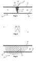
- Fig. 1 shows a gas pipe 12 below the surface 14 of the ground 16.
- the pipe 12 is thus entirely surrounded by ground material 16.
- the pipe 12 is positioned below the ground surface 14.
- the pipe 12 carries the tracer gas 18 in the direction of arrow 20 in Fig. 1 .
- the pipe 12 contains a tracer gas 18 only and no utility gas 26.
- the tracer gas 18 enters the pipe 12 upstream of the leak 22 and exits the pipe 12 through the leak 22.
- Fig. 1 shows how the tracer gas 18 spreads out of the leak 22 and within the ground 16.
- a fairly narrow plume 24 of tracer gas 18 forms within the soil.
- the plume 24 is very narrow at the leak position 22 and expands until it reaches the ground surface 14.
- Fig. 2 shows the tracer gas concentration at the surface 14. It can be realized that the diameter of the tracer gas concentration at the surface 14 is about one meter. This is typical in the case of hydrogen and helium. The diameter of the tracer gas plume 24 at the surface 14 will increase over time. Therefore, it is desirable to perform the leak detection or pin-pointing shortly after introduction of the tracer gas 18 to the pipe 12.
- Fig. 3 shows the case where the pipe 12 only carries a utility gas 26 but no tracer gas 18.
- the gas is carried in the direction of arrow 20 in Fig. 3 .
- the utility gas 26 will exit the pipe 12 at the position of the leak 22 and it will expand throughout the surrounding ground material 16 in an area which is much wider than the area of the tracer gas plume 24 in Fig. 1 .
- Fig. 4 shows an example of the concentration profile of the utility gas 26 at the surface 14 which will form according to Fig. 3 .
- the leaking utility gas 26 will form a cloud within the ground 16 and reach an outer diameter typically in the range between 5 and 25 meters at the surface 14. It can be immediately realized that it will be very hard and imprecise to detect the position of the leak 22 only from measuring the gas 18 at the surface 14. Several spots with concentration peaks are commonly found depending on the conditions of the soil and top coating (cracks etc).
- Fig. 5 now shows the embodiment of the invention where the pipe 12 carries a utility gas 26 such as methane and a tracer gas 18 such as preferably hydrogen or helium.
- the utility gas 26 is guided through the pipe 12 during normal operation, i.e. during transportation of the utility gas through the pipe.
- the tracer gas 18 is additionally injected during transportation of the utility gas 26.
- Fig. 5 shows that both the utility gas 26 and the tracer gas 18 escape from the leak 22 into the ground 16.
- the ground 16 is saturated with a large volume of utility gas 26 which expands within a very large area of the ground surface 14, as explained above with regard to Figs. 3 and 4 .
- the hydrogen or helium tracer gas 18 ascends within the ground 16 from the leak 22 up to the surface 14 without expanding as much as the utility gas 26.
- the tracer gas 18 is detected with a sniffing probe 28 above the surface 14.
- the sniffing probe 28 is at least ten times more sensitive to the tracer gas 28 than to the utility gas 26.
- Fig. 6 shows the concentration profile on the surface 14 of the utility gas 26 and of the tracer gas 18.
- the gas detector 28 When using the gas detector 28 according to the method of the invention which is much more sensitive to the tracer gas 18 than to the utility gas 26, the gas detector 28 will selectively detect the tracer gas 18 within its much more narrow expansion area 30 at the surface 14 compared to the expansion area 29 of the utility gas 26. Consequently, the possible position of the leak 22 of the gas pipe 12 can be found within a considerably smaller area when using the method of the invention compared to leak detection methods which require detecting the utility gas 26 at the ground surface 14.
Landscapes
- Physics & Mathematics (AREA)
- General Physics & Mathematics (AREA)
- Examining Or Testing Airtightness (AREA)
Abstract
Description
- The present invention relates to a method for precise pin-pointing of leaks in underground gas pipes.
- Regulations throughout the world require regular survey of gas networks to check for unknown leakage. The reason for this is primarily to protect the public from fires and explosions resulting from gas collecting in buildings and other confined spaces. The leak survey is typically carried out by moving a detector, sensitive to one of the main components of the gas, over the surface of the ground above the pipe carrying the gas.
- If leakage is detected in an underground gas line, the location of the leak must be pin-pointed to reduce the excavation work to a minimum. This has long posed difficult problems for repair crews. Although the gas line itself is often located, the soil is often saturated with gas, which makes it difficult to pin-point the actual location of the leak. As a result, it is not uncommon for large stretches of a surface, including paved roadways, to require excavation to precisely locate the leak - a situation that can be costly, time consuming, and potentially hazardous.
- The most common pin-pointing procedure on hard coated surfaces is roughly the following:
- Probe holes are drilled through the hard cover at 1 to 2 m distance in the area where the gas leak was detected. The holes are drilled right above and along the route of the presumably leaking pipe.
- The holes are left to ventilate for a while. A detector "sniffer" is placed in the holes and measures the gas concentration pumped out of the hole by the detector.
- Further and more closely spaced holes are drilled around the hole or holes showing the highest concentration until the crew feel that accuracy is satisfactory or that better accuracy cannot be achieved.
- There are two reasons for making the holes:
- Reducing the influence of ground and surface conditions on the position of the highest concentration making it appear somewhere else than right above the actual leak, and
- to allow venting out the gas from the soil so that the gas concentration profile is in a steady state and thereby improving precision of pin-pointing. To achieve a steady state situation it is vital that the holes are going most or all of the way down to the leaking pipe. It is also important that the holes are big enough to allow proper ventilation of the accumulated gas.
- The process of drilling holes requires special equipment such as a drilling machine and a power source for the drill. The power source is typically either a compressed air unit or an electric power generator. In either case it adds to the complexity of the whole operation.
- In addition to the time and effort spent there are also two serious risks involved:
- When drilling a whole there is a risk that a large amount of gas is released that could be ignited by sparks formed when drilling or by some other ignition source, and
- the pipe may be damaged from the drilling which can cause substantial leakage with associated fire and explosion risks.
- The current method is time consuming and not as accurate as desired. The main reason for the limited accuracy is that the leak is typically rather old meaning the gas has had time to spread quite a bit sideways. Typically gas is detected in an area stretching 5 to 20 meters along the route of the pipe. Considerable larger areas are often encountered and it is also common that gas is detected not directly above the pipe but instead beside the pipe at the edge of the road or sidewalk or along the curb. This also means that it is quite common to find more than one gas area from one leak.
- Typical accuracy using the probe hole procedure is +/- 2 m but it is common that two or more holes show peak concentrations forcing the crew to dig in the wrong place or to dig more than would be necessary if more accurate pin-pointing was possible.
-
US 5,063,772 A discloses a method for detecting the location of a gas leak in a gas-lift well. A tracer gas is injected into the well and external leakage is detected by recording the expected delay in gas pulse migration to a sampling and detection point. The tracer gas is detected inside the pipe as it is tapped at a location downstream of the leak position. The method thus needs two access points to the well, namely one for injecting the tracer gas and the other one for tapping a portion of the fluid for analysis of tracer content. The accuracy of the estimation of the leak position depends on several parameters including distance between the injection point and the tapping point, temperature, dimension stability and tolerance of the piping and atmospheric pressure. -
FR 2 304 911 A1 -
WO 2005/036100 A2 describes a method for locating leaks in pipelines using tracers. The method is also not applied during normal operation, i.e. not during transport of utility gas through the pipeline. Timing of gas pulses running inside the pipe and detected at a second extraction point is used as the indicator to calculate the location. This method cannot be employed during normal operation of the pipeline when utility gas is transported. -
WO 2004/113862 A1 discloses a method for leak detection in contaminated environments. The container which is tested is filled with a tracer gas and the presence of tracer gas outside of the object is detected. - It is an object of the present invention to provide an improved method for pinpointing leaks in buried gas pipes by injecting a tracer gas in the pipe shortly before performing the pin-pointing operation.
- This is achieved in accordance with the characterizing portion of claim 1.
- The method of the invention employs use of a tracer gas for leak detection. The tracer gas is injected into the utility gas within the pipe during normal operation of the pipe, i.e. when the pipe is in service and utility gas is transported through the pipe. Utility gas transport is not interrupted for the leak detection. The tracer gas is injected into the pipe at a first position and the probe measurement for leak detection is performed almost instantly, i.e. within hours of the injection, at a second position downstream of the pipe while the pipe is in normal service guiding utility gas there through. A gas detector is then used which has a higher sensitivity to the tracer gas than to the utility gas. This means that the gas detector would not be disturbed by the higher concentration of utility gas present in case of a leak. The gas detector is used to pinpoint the leak position by testing gas above the ground surface. Small amounts of tracer gas which has escaped through a leak and ascended through the soil towards and through the ground surface can be detected close to and above the ground surface with the gas detector. Detection of tracer gas is a strong indication that a pipe directly below the gas detector comprises a leak.
- Unlike the prior art leak detection methods for buried utility gas pipelines, the utility gas transport through the pipe does not have to be stopped in order to perform the leak pinpointing procedure. The tracer gas can be injected into the pipe together with the utility gas at the same position, namely at the entrance of the pipe or at any suitable access point upstream of the suspected leak area. The accuracy of locating a leak is independent of the total length of the pipe, the pressure, the temperature and the pipe dimension. The accuracy rather only depends on ground conditions and is typically better than +/- 0,5 m and typically within +/- 0,2 m.
- By injecting a tracer gas into the leaking pipe for which there is a selective and sensitive detector pin-pointing the leak will become more accurate and considerably easier to perform as the gas will not have time to spread widely in the ground before the pin-pointing work begins.
- This is achieved by following phenomena:
- The spread of the added gas is minimal as it started leaking just recently (hours before pin-pointing).
- The two most advantageous tracer gases to use are hydrogen and helium. There are selective detectors for both these gases. The addition of helium would reduce the energy content of the gas and hence affect the efficiency of the appliances using the gas.
- By choosing hydrogen the influence on the utility gas will be minimal and there are suitable selective detectors on the market. Hydrogen readily rises to the surface and penetrates most surface layers without the need for drilling probe holes. This behaviour of hydrogen has been utilized extensively by telecom organisations around the world since over 25 years. Traditional copper telephone cables, buried in the ground, are normally pressurised with dry air to prevent water ingress in case of damages to the cable sheath. This will result in air leaking out instead of water penetrating into the cable. If leaks are too big, however, they need to be found and repaired. By injecting a diluted hydrogen mixture it is possible to precisely locate such damage by searching the surface above the cable in the way described in this document. The typical accuracy of locating such leaks is less than one meter and mostly within +/-0.5 meters.
- The method according to the present invention requires the use of a highly selective detector that will react much stronger to the added tracer gas than to the gas originally in the pipe. The selectivity factor should preferably be several orders of magnitude for optimal employment of this method. Detectors with this quality are manufactured and sold by INFICON AB in Sweden. The selectivity of this detector for hydrogen as compared to methane is more than 5 orders of magnitude.
- Furthermore, the need for drilling probe holes will be greatly reduced when employing the present invention.
- The method further requires access to suitable injection points which are possible points for connecting and injecting the tracer gas into the pipe.
- Using a lighter than air tracer gas is preferable as the light atoms or molecules will ascend faster through the soil above the pipe towards the ground surface.
- An embodiment of the invention is described with reference to the drawings.
- Fig. 1
- shows the arrangement for performing the method of the invention under use of mere tracer gas,
- Fig. 2
- shows the tracer gas concentration at the surface,
- Fig. 3
- shows the arrangement of
Fig. 1 by use of mere utility gas without tracer gas, - Fig. 4
- shows the utility gas concentration profile at the surface,
- Fig. 5
- shows the arrangement according to
Fig. 1 by use of a utility gas and the tracer gas of the invention and - Fig. 6
- shows the gas concentrations at the surface.
-
Fig. 1 shows agas pipe 12 below thesurface 14 of theground 16. Thepipe 12 is thus entirely surrounded byground material 16. Thepipe 12 is positioned below theground surface 14. - The
pipe 12 carries thetracer gas 18 in the direction ofarrow 20 inFig. 1 . Thepipe 12 contains atracer gas 18 only and noutility gas 26. Thetracer gas 18 enters thepipe 12 upstream of theleak 22 and exits thepipe 12 through theleak 22. -
Fig. 1 shows how thetracer gas 18 spreads out of theleak 22 and within theground 16. A fairlynarrow plume 24 oftracer gas 18 forms within the soil. Theplume 24 is very narrow at theleak position 22 and expands until it reaches theground surface 14. -
Fig. 2 shows the tracer gas concentration at thesurface 14. It can be realized that the diameter of the tracer gas concentration at thesurface 14 is about one meter. This is typical in the case of hydrogen and helium. The diameter of thetracer gas plume 24 at thesurface 14 will increase over time. Therefore, it is desirable to perform the leak detection or pin-pointing shortly after introduction of thetracer gas 18 to thepipe 12. -
Fig. 3 shows the case where thepipe 12 only carries autility gas 26 but notracer gas 18. The gas is carried in the direction ofarrow 20 inFig. 3 . This is not an embodiment of the invention, but rather shown for illustration purposes. Theutility gas 26 will exit thepipe 12 at the position of theleak 22 and it will expand throughout the surroundingground material 16 in an area which is much wider than the area of thetracer gas plume 24 inFig. 1 . -
Fig. 4 shows an example of the concentration profile of theutility gas 26 at thesurface 14 which will form according toFig. 3 . The leakingutility gas 26 will form a cloud within theground 16 and reach an outer diameter typically in the range between 5 and 25 meters at thesurface 14. It can be immediately realized that it will be very hard and imprecise to detect the position of theleak 22 only from measuring thegas 18 at thesurface 14. Several spots with concentration peaks are commonly found depending on the conditions of the soil and top coating (cracks etc). -
Fig. 5 now shows the embodiment of the invention where thepipe 12 carries autility gas 26 such as methane and atracer gas 18 such as preferably hydrogen or helium. Theutility gas 26 is guided through thepipe 12 during normal operation, i.e. during transportation of the utility gas through the pipe. Thetracer gas 18 is additionally injected during transportation of theutility gas 26.Fig. 5 shows that both theutility gas 26 and thetracer gas 18 escape from theleak 22 into theground 16. Theground 16 is saturated with a large volume ofutility gas 26 which expands within a very large area of theground surface 14, as explained above with regard toFigs. 3 and4 . - The hydrogen or
helium tracer gas 18, however, ascends within theground 16 from theleak 22 up to thesurface 14 without expanding as much as theutility gas 26. Thetracer gas 18 is detected with a sniffingprobe 28 above thesurface 14. The sniffingprobe 28 is at least ten times more sensitive to thetracer gas 28 than to theutility gas 26. -
Fig. 6 shows the concentration profile on thesurface 14 of theutility gas 26 and of thetracer gas 18. - When using the
gas detector 28 according to the method of the invention which is much more sensitive to thetracer gas 18 than to theutility gas 26, thegas detector 28 will selectively detect thetracer gas 18 within its much morenarrow expansion area 30 at thesurface 14 compared to theexpansion area 29 of theutility gas 26. Consequently, the possible position of theleak 22 of thegas pipe 12 can be found within a considerably smaller area when using the method of the invention compared to leak detection methods which require detecting theutility gas 26 at theground surface 14.
Claims (13)
- Method for detecting the location of a gas leak (22) in a buried utility gas pipe (12) by measuring the presence of a gas (18) below or above the ground surface (14) above the pipe (12),
characterized in that
a utility gas is guided through the pipe in a mode of normal operation of the pipe (12),
a tracer gas (18) is injected into the utility gas (26) within the pipe (12) during the mode of normal operation, and
a gas detector (28) having a higher sensitivity to the tracer gas (18) than to the utility gas (26) is used to pin-point the leak position (22). - The method according to claim 1, wherein the tracer gas (18) is lighter than air.
- The method according to claim 1 or 2, wherein the tracer gas (18) is hydrogen.
- The method according to claim 1 or 2, wherein the tracer gas (18) is helium.
- The method according to one of claims 1 - 4, wherein the gas detector (28) is at least ten times more sensitive to the tracer gas (18) than to the utility gas (26).
- The method according to one of the preceding claims, wherein the gas detector (28) is at least a hundred times more sensitive to the tracer gas (18) than to the utility gas (26).
- The method according to one of the preceding claims, wherein the gas detector (28) is at least a thousand times more sensitive to the tracer gas (18) than to the utility gas (26).
- The method according to one of the preceding claims, wherein the tracer gas (18) is at least ten thousand times more sensitive to the tracer gas (18) than to the utility gas (26).
- The method according to one of the preceding claims, wherein the tracer gas (18) is injected into the gas pipe (12) upstream of the assumed leak (22).
- The method according to one of the preceding claims, wherein the tracer gas (18) is injected into the gas pipe (12) such that the pressure within the gas pipe (12) is higher than atmosphere.
- The method according to one of the preceding claims, wherein the tracer gas (18) is injected no longer than 48 hours before performing the leak detection.
- The method according to one of the preceding claims, wherein the tracer gas (18) is injected into the pipe (12) no longer than 18 hours and, preferably, no longer than 12 hours before performing the leak detection.
- The method according to one of the preceding claims, wherein the tracer gas (18) is injected into the pipe (12) at least 30 minutes and no longer than 8 hours before performing the leak detection.
Priority Applications (2)
| Application Number | Priority Date | Filing Date | Title |
|---|---|---|---|
| EP14183873.0A EP2993456A1 (en) | 2014-09-08 | 2014-09-08 | Method for selective pin-pointing of utility gas leaks during operation |
| PCT/EP2015/068695 WO2016037797A1 (en) | 2014-09-08 | 2015-08-13 | Method for selective pin-pointing of utility gas leaks during operation |
Applications Claiming Priority (1)
| Application Number | Priority Date | Filing Date | Title |
|---|---|---|---|
| EP14183873.0A EP2993456A1 (en) | 2014-09-08 | 2014-09-08 | Method for selective pin-pointing of utility gas leaks during operation |
Publications (1)
| Publication Number | Publication Date |
|---|---|
| EP2993456A1 true EP2993456A1 (en) | 2016-03-09 |
Family
ID=51492214
Family Applications (1)
| Application Number | Title | Priority Date | Filing Date |
|---|---|---|---|
| EP14183873.0A Withdrawn EP2993456A1 (en) | 2014-09-08 | 2014-09-08 | Method for selective pin-pointing of utility gas leaks during operation |
Country Status (2)
| Country | Link |
|---|---|
| EP (1) | EP2993456A1 (en) |
| WO (1) | WO2016037797A1 (en) |
Families Citing this family (1)
| Publication number | Priority date | Publication date | Assignee | Title |
|---|---|---|---|---|
| CN114413181B (en) * | 2021-12-17 | 2024-05-10 | 北京市燃气集团有限责任公司 | Tracing and positioning method for leakage points of side-by-side buried gas pipelines |
Citations (7)
| Publication number | Priority date | Publication date | Assignee | Title |
|---|---|---|---|---|
| FR2304911A1 (en) | 1975-03-18 | 1976-10-15 | Leybold Heraeus Gmbh & Co Kg | Pipeline gas leak detection system with fast response - uses carrier and test gases of nitrogen and helium |
| US5063772A (en) | 1989-03-14 | 1991-11-12 | Shell Oil Company | Method for troubleshooting gas-lift wells |
| EP0953833A1 (en) * | 1998-04-29 | 1999-11-03 | Linde Aktiengesellschaft | Method of detecting leaks in gas pipe lines |
| WO2004113862A1 (en) | 2003-06-11 | 2004-12-29 | Varian, Inc. | Methods and apparatus for leak detection in contaminated environments |
| WO2005036100A2 (en) | 2003-10-06 | 2005-04-21 | Vista Engineering Technologies, L.L.C. | Method and apparatus for locating leak holes in pipeline using tracers |
| US20110219855A1 (en) * | 2008-09-09 | 2011-09-15 | R + I Alliance | Method and device for detecting leaks in an underground liquid pipe, particularly a water pipe |
| WO2013131914A2 (en) * | 2012-03-06 | 2013-09-12 | Untergrundspeicher- Und Geotechnologie-Systeme Gmbh | Method for testing the tightness of cavities and device for decreasing convection and diffusion flow |
-
2014
- 2014-09-08 EP EP14183873.0A patent/EP2993456A1/en not_active Withdrawn
-
2015
- 2015-08-13 WO PCT/EP2015/068695 patent/WO2016037797A1/en not_active Ceased
Patent Citations (7)
| Publication number | Priority date | Publication date | Assignee | Title |
|---|---|---|---|---|
| FR2304911A1 (en) | 1975-03-18 | 1976-10-15 | Leybold Heraeus Gmbh & Co Kg | Pipeline gas leak detection system with fast response - uses carrier and test gases of nitrogen and helium |
| US5063772A (en) | 1989-03-14 | 1991-11-12 | Shell Oil Company | Method for troubleshooting gas-lift wells |
| EP0953833A1 (en) * | 1998-04-29 | 1999-11-03 | Linde Aktiengesellschaft | Method of detecting leaks in gas pipe lines |
| WO2004113862A1 (en) | 2003-06-11 | 2004-12-29 | Varian, Inc. | Methods and apparatus for leak detection in contaminated environments |
| WO2005036100A2 (en) | 2003-10-06 | 2005-04-21 | Vista Engineering Technologies, L.L.C. | Method and apparatus for locating leak holes in pipeline using tracers |
| US20110219855A1 (en) * | 2008-09-09 | 2011-09-15 | R + I Alliance | Method and device for detecting leaks in an underground liquid pipe, particularly a water pipe |
| WO2013131914A2 (en) * | 2012-03-06 | 2013-09-12 | Untergrundspeicher- Und Geotechnologie-Systeme Gmbh | Method for testing the tightness of cavities and device for decreasing convection and diffusion flow |
Also Published As
| Publication number | Publication date |
|---|---|
| WO2016037797A1 (en) | 2016-03-17 |
Similar Documents
| Publication | Publication Date | Title |
|---|---|---|
| EP2831557B1 (en) | Leak location detection system | |
| CN107271110B (en) | A kind of steel gas pipe underground leak point positioning detection method based on Big Dipper positioning | |
| US20070051165A1 (en) | Method and apparatus for detecting and locating leak holes in a pipeline using tracers | |
| CN102086972A (en) | Method for detecting leaking point position of buried pipeline by gas | |
| Mergelas et al. | Leak locating method for precommissioned transmission pipelines: North American case studies | |
| Maazallahi et al. | Intercomparison of detection and quantification methods for methane emissions from the natural gas distribution network in Hamburg, Germany | |
| CN105114821A (en) | Detection method for leakage of buried metal pipeline | |
| EP2778644A1 (en) | Method for selective pin-pointing of utility gas leaks | |
| US8950243B2 (en) | Method of testing for leaks in a contained system | |
| WO2016037797A1 (en) | Method for selective pin-pointing of utility gas leaks during operation | |
| CA2714125C (en) | Method of testing for leaks in a contained system | |
| CN107093469B (en) | Hydrogen gas lines anti-leak and leakage detection method in nuclear power station | |
| Ghafurian et al. | Leak location in fluid filled cables using the PFT method | |
| CN115978467B (en) | Underground gas pipeline leakage point positioning method and system based on negative pressure driving | |
| KR101949768B1 (en) | Detecting method of pore area in underground pipes | |
| Erizaldy et al. | Leak detection on water distribution networks using helium gas | |
| Cataldo et al. | An electromagnetic-based method for pinpointing leaks in buried pipes: a practical validation | |
| Krivoi et al. | Improvements of an inspection technique for unpiggable pipeline diagnostics from above ground | |
| CN120368226A (en) | A method for detecting water leakage in pipeline | |
| Cooper et al. | Evaluation of Techniques for Locating Leaks in Underground Heat Distribution Systems. | |
| SU712712A1 (en) | Method of determining local zone of leakage of cryogenic pipeline | |
| Oh et al. | Laboratory tests for the development of contaminant leakage detection system in soil | |
| Heiser et al. | Using perfluorocarbon tracers for verification of cap and cover systems performance. | |
| CN114413180A (en) | Buried gas pipeline leakage detection method based on neon tracing and positioning | |
| Cannata | Leakage phenomena control methods to ensure high integrity and safety standards in pipeline systems |
Legal Events
| Date | Code | Title | Description |
|---|---|---|---|
| PUAI | Public reference made under article 153(3) epc to a published international application that has entered the european phase |
Free format text: ORIGINAL CODE: 0009012 |
|
| AK | Designated contracting states |
Kind code of ref document: A1 Designated state(s): AL AT BE BG CH CY CZ DE DK EE ES FI FR GB GR HR HU IE IS IT LI LT LU LV MC MK MT NL NO PL PT RO RS SE SI SK SM TR |
|
| AX | Request for extension of the european patent |
Extension state: BA ME |
|
| 17P | Request for examination filed |
Effective date: 20160903 |
|
| RBV | Designated contracting states (corrected) |
Designated state(s): AL AT BE BG CH CY CZ DE DK EE ES FI FR GB GR HR HU IE IS IT LI LT LU LV MC MK MT NL NO PL PT RO RS SE SI SK SM TR |
|
| 17Q | First examination report despatched |
Effective date: 20161014 |
|
| STAA | Information on the status of an ep patent application or granted ep patent |
Free format text: STATUS: EXAMINATION IS IN PROGRESS |
|
| STAA | Information on the status of an ep patent application or granted ep patent |
Free format text: STATUS: THE APPLICATION IS DEEMED TO BE WITHDRAWN |
|
| 18D | Application deemed to be withdrawn |
Effective date: 20170225 |