EP2993344A1 - Fatigue evaluation system for wind turbine power generating facility - Google Patents
Fatigue evaluation system for wind turbine power generating facility Download PDFInfo
- Publication number
- EP2993344A1 EP2993344A1 EP15159764.8A EP15159764A EP2993344A1 EP 2993344 A1 EP2993344 A1 EP 2993344A1 EP 15159764 A EP15159764 A EP 15159764A EP 2993344 A1 EP2993344 A1 EP 2993344A1
- Authority
- EP
- European Patent Office
- Prior art keywords
- cumulative damage
- damage level
- total cumulative
- evaluation
- fatigue
- Prior art date
- Legal status (The legal status is an assumption and is not a legal conclusion. Google has not performed a legal analysis and makes no representation as to the accuracy of the status listed.)
- Withdrawn
Links
Images




Classifications
-
- F—MECHANICAL ENGINEERING; LIGHTING; HEATING; WEAPONS; BLASTING
- F03—MACHINES OR ENGINES FOR LIQUIDS; WIND, SPRING, OR WEIGHT MOTORS; PRODUCING MECHANICAL POWER OR A REACTIVE PROPULSIVE THRUST, NOT OTHERWISE PROVIDED FOR
- F03D—WIND MOTORS
- F03D17/00—Monitoring or testing of wind motors, e.g. diagnostics
-
- F—MECHANICAL ENGINEERING; LIGHTING; HEATING; WEAPONS; BLASTING
- F05—INDEXING SCHEMES RELATING TO ENGINES OR PUMPS IN VARIOUS SUBCLASSES OF CLASSES F01-F04
- F05B—INDEXING SCHEME RELATING TO WIND, SPRING, WEIGHT, INERTIA OR LIKE MOTORS, TO MACHINES OR ENGINES FOR LIQUIDS COVERED BY SUBCLASSES F03B, F03D AND F03G
- F05B2270/00—Control
- F05B2270/30—Control parameters, e.g. input parameters
- F05B2270/332—Maximum loads or fatigue criteria
-
- Y—GENERAL TAGGING OF NEW TECHNOLOGICAL DEVELOPMENTS; GENERAL TAGGING OF CROSS-SECTIONAL TECHNOLOGIES SPANNING OVER SEVERAL SECTIONS OF THE IPC; TECHNICAL SUBJECTS COVERED BY FORMER USPC CROSS-REFERENCE ART COLLECTIONS [XRACs] AND DIGESTS
- Y02—TECHNOLOGIES OR APPLICATIONS FOR MITIGATION OR ADAPTATION AGAINST CLIMATE CHANGE
- Y02E—REDUCTION OF GREENHOUSE GAS [GHG] EMISSIONS, RELATED TO ENERGY GENERATION, TRANSMISSION OR DISTRIBUTION
- Y02E10/00—Energy generation through renewable energy sources
- Y02E10/70—Wind energy
- Y02E10/72—Wind turbines with rotation axis in wind direction
Definitions
- the present invention relates to a fatigue evaluation system for a wind turbine power generating facility.
- a wind turbine power generating facility generally includes a rotor including a plurality of rotor blades for receiving wind energy and a rotor hub, a generator to which rotational force of the rotor is transmitted via a drive train, a nacelle which rotatably supports the rotor and accommodates the generator, a tower which supports the nacelle, and the like.
- Patent Document 1 discloses a monitoring system for a wind turbine power generating facility, configured to evaluate fatigue of components of the wind turbine power generating facility such as rotor blades and a drive train using a rain-flow process.
- Patent Document 1 EP 1760311
- Patent Document 1 does not describe a specific evaluation method such as a calculation method of cumulative damage degree for evaluating fatigue, and does not sufficiently disclose findings for appropriately evaluating fatigue of each part of the wind turbine power generating facility.
- An object of at least one embodiment of the present invention is to provide a fatigue evaluation system for a wind turbine power generating facility which enables appropriate fatigue evaluation of each part of a wind turbine power generating facility.
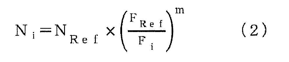
- N i N Ref ⁇ F Ref F i m
- N Ref is a fracture repetition number corresponding to a reference stress amplitude F Ref
- m is a slope of a function representing a relationship between the fracture repetition number N i and the stress amplitude F i in the information of the S-N linear chart.
- the fatigue evaluation system described in the above (1) further includes a warning signal generation part configured to generate a warning signal when the total cumulative damage level D t of at least one of the evaluating points calculated by the total cumulative damage level calculation part has exceeded the threshold value.
- the warning signal generation part is configured to generate the warning signal also when an increasing speed of the total cumulative damage level D t of at least one of the evaluation points calculated by the total cumulative damage level calculation part has exceeded a tolerance.
- the warning signal generation part of the fatigue evaluation system described in the above (3) generates a warning signal for warning in such a situation, so that it possible to take an appropriate measure such as shutdown and maintenance of the wind turbine power generating facility in response to the warning.
- the threshold value is 1.
- the total cumulative damage level D t of each evaluation point calculated by the total cumulative damage level calculation part is compared to 1, which is a value indicating the design life time. In this way, it is possible to accurately obtain the residual life time of a part to which each evaluation point belongs, on the basis of the cumulative fatigue damage rule.
- the threshold value increases with an elapsed time after starting operation of the wind turbine power generating facility.
- the total cumulative damage level D t at each evaluation point increases with an elapsed time after starting operation of the wind turbine power generating facility.
- the threshold value which is to be compared to the total cumulative damage level D t , is increased in accordance with the elapsed time after starting operation of the wind turbine power generating facility, which makes it possible to appropriately determine whether the total cumulative damage level D t at each evaluation point is a normal value, at a certain point of time.
- the unit period is a period of not less than 1 minute and not more than 600 minutes.
- At least one of the evaluation points belongs to one of a top part of a tower, a bottom part of the tower, a rotor hub, or a rotor blade.
- the wind turbine power generating facility includes a plurality of rotor blades mounted to the rotor hub, and each of the rotor blades includes at least one of the evaluation points.
- the fatigue evaluation system further comprises a defect determination part configured to determine a defect of each of the rotor blades, by comparing the total cumulative damage level D t of the at least one evaluation point of each of the rotor blades, calculated by the total cumulative damage level calculation part, to one another.
- the time average values (average values over a time longer enough than the rotational period of the rotor) of stress generated on the identical locations (for instance, the blade root portion of one rotor blade and the blade root portion of another rotor blade) of the rotor blades are basically substantially the same, because the rotor rotates.
- it is possible to determine the defect of each rotor blade by comparing the total cumulative damage levels D t of the evaluation points belonging to the rotor blades to one another.
- the stress amplitude information calculation part is configured to calculate the stress amplitude F i and repetition number n i of the stress amplitude F i of the stress generated on each of the evaluation points within the unit period, by executing a rain flow process on the stress change information obtained by the stress change information acquisition part.
- the fatigue evaluation system described in the above (1) to (9) further includes a display part configured to display a graph of the total cumulative damage level D t of each of the evaluation points calculated by the total cumulative damage level calculation part.
- the fatigue evaluation system described in the above (1) to (10) further includes a measurement device for measuring the stress generated on each of the evaluation points of the wind turbine power generating facility.
- the stress change information acquisition part is configured to obtain the stress change information from the measurement device.
- the stress change information acquisition part obtains the stress change information related to the real-time stress generated at each evaluation point of the wind turbine power generation facility via the measurement device.
- the stress change information related to the real-time stress generated at each evaluation point it is possible to calculate the total cumulative damage level D t at each evaluation point after a start of operation of the wind turbine power generating facility and before the current time with the total cumulative damage level calculation part.
- comparing the total cumulative damage level D t calculated as described above to the threshold value corresponding to e.g. the design life time makes it possible to accurately evaluate the residual life time of each part of the wind turbine power generating facility.
- the total cumulative damage level calculation part is configured to refresh the total cumulative damage level D t every time the unit period elapses, by adding the cumulative damage level D u of a latest unit period to a previous value of the total cumulative damage level D t for each of the evaluation points.
- the fatigue evaluation system further includes a flag setting part configured to, when the total cumulative damage level D t of at least one of the evaluation points calculated by the total cumulative damage level calculation part has exceeded the threshold value at least once, turn on a flag which indicates that the total cumulative damage level D t has exceeded the threshold value at the at least one evaluation point.
- the fatigue evaluation system described in the above (12) further includes a measurement device for measuring the stress generated on each of the evaluation points of the wind turbine power generating facility.
- the stress change information acquisition part is configured to obtain the stress change information from the measurement device.
- the flag setting part is configured to, only when the total cumulative damage level D t of at least one of the evaluation points calculated by the total cumulative damage level calculation part has exceeded the threshold value more than once in series, turn on a flag which indicates that the total cumulative damage level D t has exceeded the threshold value for the at least one evaluation point.
- the stress change information acquisition part obtains the stress change information related to the real-time stress generated at each evaluation point of the wind turbine power generation facility via the measurement device.
- the total cumulative damage level D t it is possible to calculate the total cumulative damage level D t at each evaluation point after a start of operation of the wind turbine power generating facility and before the current time with the total cumulative damage level calculation part, on the basis of the stress change information related to the real-time stress generated on each evaluation point.
- the stress change information obtained by the measurement device includes dispersion due to temporal disturbance.
- the calculated total cumulative damage level D t may be also affected by this dispersion.
- the flag indicating that the total cumulative damage level D t of the evaluation point has exceeded the threshold value is turned on only when the total cumulative damage level D t of at least one evaluation point has exceeded the threshold value more than once in series.
- the flag setting part is configured to, only when the total cumulative damage level D t of at least one evaluation point calculated by the total cumulative damage level calculation part has fallen to the threshold value or less, more than once in series, turn off the flag for the at least one evaluation point.
- a wind turbine power generating facility includes: a rotor configured to rotate upon receiving wind energy; a generator to which rotational force of the rotor is transmitted; and the fatigue evaluation system according to any one of the above (1) to (14).
- a fatigue evaluation system of a wind turbine power generating facility capable of appropriately evaluating fatigue of each part of the wind turbine power generating facility.
- an expression of relative or absolute arrangement such as “in a direction”, “along a direction”, “parallel”, “orthogonal”, “centered”, “concentric” and “coaxial” shall not be construed as indicating only the arrangement in a strict literal sense, but also includes a state where the arrangement is relatively displaced by a tolerance, or by an angle or a distance whereby it is possible to achieve the same function.
- an expression of a shape such as a rectangular shape or a cylindrical shape shall not be construed as only the geometrically strict shape, but also includes a shape with unevenness or chamfered corners within the range in which the same effect can be achieved.
- FIG. 1 is a schematic diagram of an overall configuration of a wind turbine power generating facility according to one embodiment of the present invention.
- the wind turbine power generating facility 1 includes a rotor 6 including a plurality of rotor blades 2 (2a, 2b, 2c) for receiving wind energy and a rotor hub 4, a generator 8 to which rotational force of the rotor 6 is transmitted via a gearbox (not illustrated), a nacelle 10 which rotatably supports the rotor 6 and accommodates the generator 8, and a tower 12 which supports the nacelle 10.
- FIG. 2 is a diagram of an exemplary configuration of a fatigue evaluation system 100 for evaluating fatigue of the wind turbine power generating facility 1.
- the fatigue evaluation system 100 illustrated in FIG. 2 includes a stress change information acquisition part 14, a stress amplitude information calculation part 16, a cumulative damage level calculation part 18, a total cumulative damage level calculation part 20, and a fatigue evaluation part 22.
- the stress change information acquisition part 14 is configured to obtain stress change information indicating the temporal change within a unit period of time of stress generated on each evaluating point of the wind turbine power generating facility 1.
- the stress amplitude information calculation part 16 is configured to calculate the stress amplitude F i and the repetition number n i of the stress amplitude F i of the stress generated on each evaluation point in a unit period, on the basis of the stress change information obtained by the stress change information acquisition part 14.
- the unit period of time is, for instance a period of not less than 1 minute and not more than 600 minutes, or a predetermined period such as 10 minutes.
- the stress amplitude information calculation part 16 may execute a rain flow process on the stress change information obtained by the stress change information acquisition part 14 to calculate the stress amplitude F i and the repeated number n i of the stress amplitude F i , of the stress generated on each evaluation point in a unit period.
- the cumulative damage level calculation part 18 is configured to calculate the cumulative damage level D u of each evaluation point within the unit period, on the basis of the calculation result calculated by the stress amplitude information calculation part 16 and the information of the S-N linear chart corresponding to the material of each evaluation point.
- N i N Ref ⁇ F Ref F i m
- N ref is the number of fracture repetition corresponding to the reference stress amplitude F ref
- m is a slope of a function representing a relationship of the fracture repetition number N i and the stress amplitude F i in the information of the S-N linear chart.
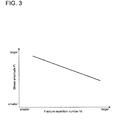
- the S-N linear chart represents how many repetition of a certain stress amplitude F i takes to cause damage.
- the S-N linear chart may be stored in a storing device 32 (see FIG. 2 ) included in the fatigue evaluation system 100 and read out when needed.
- the total cumulative damage level calculation part 20 is configured to calculate the total cumulative damage level D t of the entire evaluation period at each evaluation point by adding up the calculation results calculated by the cumulative damage level calculation part 18 throughout the entire evaluation period. Further, the total cumulative damage level calculation part 20 is configured to add the cumulative damage level D u of the latest unit period to the previous value of the total cumulative damage level D t for each evaluation point to refresh the total cumulative damage level D t every time a unit period elapses.
- Evaluation period here may be a period corresponding the design life time of the wind turbine power generating facility 1, the cumulative usage period of the wind turbine power generating facility 1 up to the evaluation point (the present time), or a total period of the cumulative usage period and a period until the next maintenance.
- the fatigue evaluation part 22 is configured to evaluate fatigue of each part of the wind turbine power generating facility 1 to which the corresponding evaluation point belongs by comparing the total cumulative damage value D t calculated by the total cumulative damage level calculation part 20 with a threshold value D th .
- the fatigue evaluation system 100 it is possible to calculate the appropriate total cumulative damage level D t taking account of the cumulative fatigue damage rule at each evaluation point, on the basis of the stress amplitude F i and repetition number n i of the stress amplitude F i of the stress generated on each evaluation point in a unit period in the wind turbine power generating facility 1, and the information of the S-N linear chart corresponding to the material of each evaluation point.
- the fatigue evaluation system 100 it is possible to appropriately evaluate fatigue of a part to which each evaluation belongs on the basis of the cumulative fatigue damage rule by comparing the total cumulative damage level D t to a threshold value.
- the fatigue evaluation system 100 includes a warning signal generation part 24 configured to generate a warning signal when the total cumulative damage level D t of at least one of the evaluation points calculated by the total cumulative damage level calculation part 20 has exceeded the threshold value D th .
- the warning signal generation part 24 When the total cumulative damage level D t exceeds a certain value, the risk of damage is increased. Thus, the warning signal generation part 24 generates a warning signal for warning when the total cumulative damage level D t exceeds the threshold value D th , which makes it possible to take an appropriate measure such as shutdown and maintenance of the wind turbine power generating facility 1 in response to the warning.
- the warning signal generation part 24 may be configured to generate a warning signal also when the increasing speed of the total cumulative damage level D t of at least one of the evaluation points calculated by the total cumulative damage level calculation part 20 has exceeded a tolerance.
- the warning signal generation part 24 generating a warning signal for warning in such a situation makes it possible to take an appropriate measure such as shutdown and maintenance of the wind turbine power generating facility 1 in response to the warning.
- the threshold value D th is set to 1.
- the total cumulative damage level D t of each of the evaluation points calculated by the total cumulative damage level calculation part 20 is compared to 1, which is a value indicating the design life time, which makes it possible to accurately obtain the residual life time of a part to which each evaluation point belongs, on the basis of the cumulative fatigue damage rule.
- the threshold value D th is set so as to increase with elapsed time after starting operation of the wind turbine power generating facility 1.
- the total cumulative damage level D t at each evaluation point increases with elapsed time after starting operation of the wind turbine power generating facility 1.
- it is necessary to appropriately vary the threshold value D th which is to be compared to the total cumulative damage level D t , in accordance with the elapsed time after starting operation of the wind turbine power generating facility 1 to appropriately determine whether the total cumulative damage level D t at each evaluation point is a normal value at a certain point of time.
- the threshold value D th which is to be compared to the total cumulative damage level D t at each evaluation point, is increased in accordance with the elapsed time after starting operation of the wind turbine power generating facility 1, which makes it possible to appropriately determine whether the total cumulative damage level D t at each evaluation point at a certain point of time is a normal value.
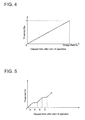
- the threshold value D th may be set so as to increase proportional to the elapsed time before the design life time as illustrated in FIG. 3 , or the increasing rate of the threshold value D th with respect to the above elapsed time may be varied for each period as illustrated in FIG.4 .
- the increase rate of the threshold value D th may be set to be large in a season with strong wind (period A) compared to a season with less strong wind (period B). In this way, it is possible to appropriately determine whether the total cumulative damage level D t at each evaluation point is a normal value.
- At least one of the evaluation points of the wind turbine power generating facility 1 belongs to one of the top part 12a of the tower 12, the bottom part 12b of the tower 12, one of the rotor blades 2, or the rotor hub 4 illustrated in FIG. 1 .
- the fatigue evaluation system 100 further includes measurement devices 28 (28a to 28f) for measuring the stress generated on each evaluation point of the wind turbine power generating facility 1, and the stress change information acquisition part 14 is configured to obtain the stress change information from the measurement device 28.
- the measurement devices 28 (28a to 28f) here may be, as illustrated in FIG. 1 , disposed on the top part 12a of the tower 12, the bottom part 12b of the tower 12, the blade root portion (2ar to 2cr) of each rotor blade 2 (2a to 2c) and the rotor hub 4, respectively.
- each measurement device 28 (28a to 28f) is a distortion sensor or a load sensor, and the stress is measured from the detection results of the sensors.
- the stress change information acquisition part 14 obtains the stress change information related to the real-time stress generated at each evaluation point of the wind turbine power generating facility 1 via the measurement devices 28 at the major locations with the risk of damage in the wind turbine power generating facility 1. Further, on the basis of the stress change information related to the real-time stress generated on each evaluation point, it is possible to calculate the total cumulative damage level D t at each evaluation point after a start of operation of the wind turbine power generating facility 1 and before the current time with the total cumulative damage level calculation part 20. Thus, comparing the total cumulative damage level D t calculated as described above to the threshold value D th corresponding to e.g. the design life time makes it possible to accurately evaluate the residual life time of each part of the wind turbine power generating facility 1.
- each of the plurality of rotor blades 2 includes at least one of the evaluation points of the fatigue evaluation system100 illustrated in FIG. 2 .
- the fatigue evaluation system100 may include a defect determination part 25 (see FIG. 2 ) configured to compare the total cumulative damage levels D t of the evaluation points belonging to the respective rotor blades calculated by the total cumulative damage level calculation part 20 with one another to determine a defect for each of the plurality of rotor blades 2.
- the time average values (average values over a time longer enough than the rotational period of the rotor 6) of the stress generated on the evaluation points of identical locations (for instance, the blade root portion 2ar of the rotor blade 2a and the blade root portion 2br of the other rotor blade 2b) of the rotor blades 2 are basically substantially the same, because the rotor rotates.
- each rotor blade 2 determines the defect of each rotor blade 2 by comparing the total cumulative damage level D t of the evaluation points belonging to the rotor blade 2a of the plurality of rotor blades 2 to the total cumulative damage level D t of the evaluation point belonging to the other at least one rotor blade 2 (2b, 2c) at the identical location.
- the defect determination part 25 may determine that the blade root portion 2ar of the rotor blade 2a has a defect when the total cumulative damage level D t of the evaluation point belonging to the rotor blade 2a is larger than the average value of the total cumulative damage levels D t of the evaluation points belonging to the blade root portions (2ar to 2br) of the entire rotor blades 2 at the identical location by a predetermined level or more (for instance, by a predetermined value or more, or by a predetermined multiple).
- the defect determination part 25 may determine that the blade root portion 2ar of the rotor blade 2a has a defect when the total cumulative damage level D t of the evaluation point belonging to the rotor blade 2a is larger than the average value of the average value of the total cumulative damage level D t of the evaluation points belonging to the blade root portions (2br, 2cr) of the other rotor blades 2 (2b, 2c) at the identical location by a predetermined level or more (for instance, by a predetermined value or more, or by a predetermined multiple).
- the fatigue evaluation system 100 includes a display part 26 (see FIG. 2 ) configured to display a graph of the total cumulative damage levels D t of the respective evaluation points calculated by the total cumulative damage level calculation part 20.
- the display part 26 may display a graph including one axis indicating the elapsed time after starting operation of the wind turbine power generating facility 1, and the other axis indicating the total cumulative damage level D t of each evaluation point.
- the display part 26 may display a line L1 indicating the temporal change between the start of operation and the current time for the total cumulative damage level D t of each evaluation point actually calculated by the total cumulative damage level calculation part 20, while also displaying a design straight line L2 of the total cumulative damage level D t after starting operation and before reaching the design life time (e.g. 25 years) of the wind turbine power generating facility 1, where the total cumulative damage level D t becomes 1 at the design lifetime.
- the fatigue evaluation system 100 includes a flag setting part 30.
- the flag setting part 30 is configured to turn on a flag indicating that the total cumulative damage level D t has exceeded the threshold value at the at least one evaluation point.
- the flag setting part 30 illustrated in FIG. 2 may be configured to turn on the flag only when the total cumulative damage level D t of at least one evaluation point calculated by the total cumulative damage level calculation part 20 has exceeded the threshold value D th more than once in series.
- the flag setting part 30 may also be configured to turn off the flag for the evaluation point only when the total cumulative damage level D t of at least one evaluation point calculated by the total cumulative damage level calculation part 20 has fallen to or below the threshold value D th more than once in series.
- the stress change information obtained by the measurement device 28 includes dispersion due to temporal disturbance.
- the calculated total cumulative damage level D t may also be affected by this dispersion.
- the flag indicating that the total cumulative damage level D t of the evaluation point has exceeded the threshold value is turned on only when the total cumulative damage level D t of at least one evaluation point calculated by the total cumulative damage level calculation part 20 has exceeded the threshold value D th more than once in series.
- the stress change information acquisition part 14 obtains, from the measurement device 28, the stress change information indicating the temporal change within a unit period of the stress generated at each evaluation point of the wind turbine power generating facility 1.
- the stress amplitude information calculation part 16 calculates the stress amplitude F i and the repetition number n i of the stress amplitude F i of the stress generated on each evaluation point within a unit period (e.g. 10 minutes) by executing a rain flow process on the stress change information obtained by the stress change information acquisition part 14.
- the cumulative damage level calculation part 18 calculates the cumulative damage level D u of each evaluation point within the above unit period. Further, in S14, the total cumulative damage level calculation part 20 calculates the total cumulative damage level D t of the entire evaluation period at each evaluation point by adding up the calculation results calculated by the cumulative damage level calculation part 18 for the entire evaluation period.
- the total cumulative damage level calculation part 20 adds the cumulative damage level D u of the latest unit period to the previous value of the total cumulative damage level D t for each evaluation point every time a unit period elapses, thereby refreshing the total cumulative damage level D t .
- the fatigue evaluation part 22 evaluates fatigue of a part to which each evaluation point belongs in the wind turbine power generating facility 1 by comparing the total cumulative damage level D t calculated by the total cumulative damage level calculation part 20 to the threshold value D th .
- the above fatigue evaluation system100 may be included in the wind turbine power generating facility 1, or may be provided as a separate system from the wind turbine power generating facility 1. Further, only a part of the fatigue evaluation system 100 (for instance, the measurement device 28 in FIG. 2 ) may be disposed in the wind turbine power generating facility 1, and the other components of the cumulative damage level evaluation system 100 may be provided separately from the wind turbine power generating facility 1.
Landscapes
- Engineering & Computer Science (AREA)
- Life Sciences & Earth Sciences (AREA)
- Sustainable Development (AREA)
- Sustainable Energy (AREA)
- Chemical & Material Sciences (AREA)
- Combustion & Propulsion (AREA)
- Mechanical Engineering (AREA)
- General Engineering & Computer Science (AREA)
- Wind Motors (AREA)
- Testing Of Devices, Machine Parts, Or Other Structures Thereof (AREA)
Abstract

Description
- The present invention relates to a fatigue evaluation system for a wind turbine power generating facility.
- Wind turbine power generating facilities utilizing wind as renewable energy to generate power have become widely used in recent years in view of preservation of the global environment. A wind turbine power generating facility generally includes a rotor including a plurality of rotor blades for receiving wind energy and a rotor hub, a generator to which rotational force of the rotor is transmitted via a drive train, a nacelle which rotatably supports the rotor and accommodates the generator, a tower which supports the nacelle, and the like.
-
Patent Document 1 discloses a monitoring system for a wind turbine power generating facility, configured to evaluate fatigue of components of the wind turbine power generating facility such as rotor blades and a drive train using a rain-flow process. - Patent Document 1:
EP 1760311 -
Patent Document 1, however, does not describe a specific evaluation method such as a calculation method of cumulative damage degree for evaluating fatigue, and does not sufficiently disclose findings for appropriately evaluating fatigue of each part of the wind turbine power generating facility. - The present invention was made in view of the above issues of the conventional technique. An object of at least one embodiment of the present invention is to provide a fatigue evaluation system for a wind turbine power generating facility which enables appropriate fatigue evaluation of each part of a wind turbine power generating facility.
- (1) A fatigue evaluation system for a wind turbine power generating facility according to one embodiment of the present invention includes: a stress change information acquisition part configured to obtain stress change information which indicates a temporal change, within a unit period, of stress which is generated on each of evaluation points of the wind turbine power generating facility; a stress amplitude information calculation part configured to calculate stress amplitude Fi and a repetition number ni of the stress amplitude Fi of the stress generated on each of the evaluating points within the unit period, on the basis of the stress change information obtained by the stress change information acquisition part; a cumulative damage level calculation part configured to calculate a cumulative damage level Du of each of the evaluation points within the unit period, on the basis of the calculation result calculated by the stress amplitude information calculation part and information of a S-N linear chart which corresponds to a material of each of the evaluation points; a total cumulative damage level calculation part configured to add up calculation results of the cumulative damage level calculation part over an entire evaluation period to calculate a total cumulative damage level Dt of the entire evaluation period for each of the evaluation points; and a fatigue evaluation part configured to compare the total cumulative damage level Dt at each of the evaluation points calculated by the total cumulative damage level calculation part to a threshold value, and evaluate fatigue of a part of the wind turbine power generating facility to which each of the evaluation points belongs. The cumulative damage level calculation part is configured to calculate the cumulative damage level Du from the following equation (1).

- In the above equation (1), Ni is a fracture repetition number which corresponds to the stress amplitude Fi, and which is calculated by the following equation (2).

- In the above equation (2), NRef is a fracture repetition number corresponding to a reference stress amplitude FRef, and m is a slope of a function representing a relationship between the fracture repetition number Ni and the stress amplitude Fi in the information of the S-N linear chart.
- With the fatigue evaluation system described in the above (1), it is possible to calculate the appropriate total cumulative damage level Dt taking account of the cumulative fatigue damage rule at each evaluation point, on the basis of the stress amplitude Fi and the repetition number ni of the stress amplitude Fi of the stress generated on each evaluation point in a unit period in the wind turbine power generating facility, and the information of the S-N linear chart corresponding to the material of each evaluation point.
- Thus, it is possible to appropriately evaluate fatigue of a part to which each evaluation belongs on the basis of the cumulative fatigue damage rule, by comparing the total cumulative damage level Dt to a threshold value.
- Accordingly, for instance, when it is anticipated that the residual life time of a part corresponding to one of the evaluation points would be over before the next regular maintenance, the next maintenance is advanced, or the operation rate of the wind turbine power generating facility is reduced to extend the residual life time to the next regular maintenance. As a result, it is possible to prevent unexpected shutdown due to damage of a part of the wind turbine power generating facility, for instance.
- (2) In some embodiments, the fatigue evaluation system described in the above (1) further includes a warning signal generation part configured to generate a warning signal when the total cumulative damage level Dt of at least one of the evaluating points calculated by the total cumulative damage level calculation part has exceeded the threshold value.
- When the total cumulative damage level Dt exceeds a predetermined value, the risk of damage is increased. Thus, with the the fatigue evaluation system described in the above (2) where the warning signal generation part generates a warning signal for warning in the above situation, it possible to take an appropriate measure such as shutdown and maintenance of the wind turbine power generating facility in response to the warning.
- (3) In some embodiments, in the fatigue evaluation system described in the above (2), the warning signal generation part is configured to generate the warning signal also when an increasing speed of the total cumulative damage level Dt of at least one of the evaluation points calculated by the total cumulative damage level calculation part has exceeded a tolerance.
- When the increasing speed of the total cumulative damage level Dt of at least one of the evaluation points of the wind turbine power generating facility has exceeded a tolerance, it is presumed that an abnormal event that causes an unexpected stress distribution has occurred in the wind turbine power generating facility. Thus, the warning signal generation part of the fatigue evaluation system described in the above (3) generates a warning signal for warning in such a situation, so that it possible to take an appropriate measure such as shutdown and maintenance of the wind turbine power generating facility in response to the warning.
- (4) In some embodiments, in the fatigue evaluation system described in any one of the above (1) to (3), the threshold value is 1.
- With the fatigue evaluation system described in the above (4), the total cumulative damage level Dt of each evaluation point calculated by the total cumulative damage level calculation part is compared to 1, which is a value indicating the design life time. In this way, it is possible to accurately obtain the residual life time of a part to which each evaluation point belongs, on the basis of the cumulative fatigue damage rule.
- (5) In some embodiments, in the fatigue evaluation system described in any one of the above (1) to (3), the threshold value increases with an elapsed time after starting operation of the wind turbine power generating facility.
- The total cumulative damage level Dt at each evaluation point increases with an elapsed time after starting operation of the wind turbine power generating facility. Thus, at a certain point of time, it is necessary to appropriately vary the threshold value, which is to be compared to the total cumulative damage level Dt, in accordance with the elapsed time after starting operation of the wind turbine power generating facility to appropriately determine whether the total cumulative damage level Dt at each evaluation point is a normal value. In this regard, with the above fatigue evaluation system described in the above (5), the threshold value, which is to be compared to the total cumulative damage level Dt, is increased in accordance with the elapsed time after starting operation of the wind turbine power generating facility, which makes it possible to appropriately determine whether the total cumulative damage level Dt at each evaluation point is a normal value, at a certain point of time.
- (6) In some embodiments, in the fatigue evaluation system described in any one of the above (1) to (5), the unit period is a period of not less than 1 minute and not more than 600 minutes.
- The shorter the unit period for calculating the cumulative damage level Du is, the more frequently it is possible to execute the fatigue evaluation based on the cumulative damage level. Thus, even when an abnormal event that leads to a rapid increase in the total cumulative damage level Dt is caused in the wind turbine power generating facility, it is possible to detect the abnormality quickly and to take an appropriate measure such as shutdown and maintenance of the wind turbine power generating facility. However, the shorter the unit period for calculating the cumulative damage level Du is, the larger the load of calculation would be in the cumulative damage level calculation part and the total cumulative damage level calculation part. In this regard, with the fatigue evaluation system described in the above (6), it is possible to calculate the cumulative damage level Du at the optimum frequency, considering both the above load of calculation and the risk of delay in detection of an abnormality that may lead to a rapid increase in the total cumulative damage level Dt in the wind turbine power generating facility.
- (7) In some embodiments, in the fatigue evaluation system described in any one of the above (1) to (6), at least one of the evaluation points belongs to one of a top part of a tower, a bottom part of the tower, a rotor hub, or a rotor blade.
- With the fatigue evaluation system described in the above (7), it is possible to calculate the appropriate total cumulative damage level Dt in consideration of the cumulative fatigue damage rule at major locations with the risk of fracture in the wind turbine power generating facility. Thus, comparing the total cumulative damage level Dt to the threshold value makes it possible to appropriately evaluate fatigue of the major locations with the risk of fracture on the basis of the cumulative fatigue damage rule.
- (8) In some embodiments, in the fatigue evaluation system described in any one of the above (1) to (7), the wind turbine power generating facility includes a plurality of rotor blades mounted to the rotor hub, and each of the rotor blades includes at least one of the evaluation points. Also, the fatigue evaluation system further comprises a defect determination part configured to determine a defect of each of the rotor blades, by comparing the total cumulative damage level Dt of the at least one evaluation point of each of the rotor blades, calculated by the total cumulative damage level calculation part, to one another.
- In a case where the wind turbine power generating facility includes a plurality of rotor blades, the time average values (average values over a time longer enough than the rotational period of the rotor) of stress generated on the identical locations (for instance, the blade root portion of one rotor blade and the blade root portion of another rotor blade) of the rotor blades are basically substantially the same, because the rotor rotates. Thus, for instance, it is possible to determine the defect of each rotor blade by comparing the total cumulative damage levels Dt of the evaluation points belonging to the rotor blades to one another.
- (9) In some embodiments, in the fatigue evaluation system described in any one of the above (1) to (8), the stress amplitude information calculation part is configured to calculate the stress amplitude Fi and repetition number ni of the stress amplitude Fi of the stress generated on each of the evaluation points within the unit period, by executing a rain flow process on the stress change information obtained by the stress change information acquisition part.
- With the fatigue evaluation system described in the above (9), it is possible to calculate the stress amplitude Fi and the repetition number ni of the stress amplitude Fi accurately by executing a rain flow process on the stress change information acquisition part.
- (10) In some embodiments, the fatigue evaluation system described in the above (1) to (9) further includes a display part configured to display a graph of the total cumulative damage level Dt of each of the evaluation points calculated by the total cumulative damage level calculation part.
- With the fatigue evaluation system described in the above (10), displaying a graph of the total cumulative damage levels Dt of the respective evaluation points as described above makes it possible for an operator to visually determine the total cumulative damage levels Dt of the respective evaluation points. Thus, it is possible for the operator to easily determine the residual lifetime or the like at each evaluation point of the wind turbine power generating facility, on the basis of the displayed graph of the total cumulative damage levels Dt. As a result, it is possible for the operator to take an appropriate measure such as shutdown and maintenance of the wind turbine power generating facility.
- (11) In some embodiments, the fatigue evaluation system described in the above (1) to (10) further includes a measurement device for measuring the stress generated on each of the evaluation points of the wind turbine power generating facility. The stress change information acquisition part is configured to obtain the stress change information from the measurement device.
- With the fatigue evaluation system described in the above (11), it is possible for the stress change information acquisition part to obtain the stress change information related to the real-time stress generated at each evaluation point of the wind turbine power generation facility via the measurement device. In this way, on the basis of the stress change information related to the real-time stress generated at each evaluation point, it is possible to calculate the total cumulative damage level Dt at each evaluation point after a start of operation of the wind turbine power generating facility and before the current time with the total cumulative damage level calculation part. Thus, comparing the total cumulative damage level Dt calculated as described above to the threshold value corresponding to e.g. the design life time makes it possible to accurately evaluate the residual life time of each part of the wind turbine power generating facility.
- (12) In some embodiments, in the fatigue evaluation system described in the above (5), the total cumulative damage level calculation part is configured to refresh the total cumulative damage level Dt every time the unit period elapses, by adding the cumulative damage level Du of a latest unit period to a previous value of the total cumulative damage level Dt for each of the evaluation points. Also, the fatigue evaluation system further includes a flag setting part configured to, when the total cumulative damage level Dt of at least one of the evaluation points calculated by the total cumulative damage level calculation part has exceeded the threshold value at least once, turn on a flag which indicates that the total cumulative damage level Dt has exceeded the threshold value at the at least one evaluation point.
- With the fatigue evaluation system described in the above (12), it is possible to specify the point of time when the total cumulative damage level Dt of the at least one evaluation point has exceeded the threshold value, on the basis of the state of the flag. Thus, for instance, it is possible to specify the cause or the like that the total cumulative damage level Dt of the evaluation point has exceeded the threshold value, by referring afterward to the operability or the like at the point of time of the devices constituting the wind turbine power generating facility.
- (13) In some embodiments, the fatigue evaluation system described in the above (12) further includes a measurement device for measuring the stress generated on each of the evaluation points of the wind turbine power generating facility. The stress change information acquisition part is configured to obtain the stress change information from the measurement device. Also, the flag setting part is configured to, only when the total cumulative damage level Dt of at least one of the evaluation points calculated by the total cumulative damage level calculation part has exceeded the threshold value more than once in series, turn on a flag which indicates that the total cumulative damage level Dt has exceeded the threshold value for the at least one evaluation point.
- With the fatigue evaluation system described in the above (13), it is possible for the stress change information acquisition part to obtain the stress change information related to the real-time stress generated at each evaluation point of the wind turbine power generation facility via the measurement device. In this way, it is possible to calculate the total cumulative damage level Dt at each evaluation point after a start of operation of the wind turbine power generating facility and before the current time with the total cumulative damage level calculation part, on the basis of the stress change information related to the real-time stress generated on each evaluation point.
- Meanwhile, the stress change information obtained by the measurement device includes dispersion due to temporal disturbance. Thus, the calculated total cumulative damage level Dt may be also affected by this dispersion. In this regard, with the above fatigue evaluation system described in the above (13), the flag indicating that the total cumulative damage level Dt of the evaluation point has exceeded the threshold value is turned on only when the total cumulative damage level Dt of at least one evaluation point has exceeded the threshold value more than once in series. Thus, it is possible to restrict the influence from the above dispersion from affecting the point of time when the flag is to be turned on.
- (14) In some embodiments, in the fatigue evaluation system described in the above (13), the flag setting part is configured to, only when the total cumulative damage level Dt of at least one evaluation point calculated by the total cumulative damage level calculation part has fallen to the threshold value or less, more than once in series, turn off the flag for the at least one evaluation point.
- With the fatigue evaluation system described in the above (14), it is also possible to restrict the influence from the above dispersion from affecting the point of time when the flag is to be turned off.
- (15) A wind turbine power generating facility according to one embodiment of the present invention includes: a rotor configured to rotate upon receiving wind energy; a generator to which rotational force of the rotor is transmitted; and the fatigue evaluation system according to any one of the above (1) to (14).
- With the wind turbine power generating facility described in the above (15), it is possible to appropriately evaluate fatigue of a part to which each evaluation point belongs, on the basis of the cumulative fatigue damage rule, by using the fatigue evaluation system described in any one of the above (1) to (14).
- Accordingly, for instance, when it is anticipated that the residual life time of a part corresponding to one of the evaluation points would be over before the next regular maintenance, the next maintenance is advanced, or the operation rate of the wind turbine power generating facility is reduced to extend the residual life time to the next regular maintenance. As a result, it is possible to prevent unexpected shutdown due to damage of each part of the wind turbine power generating facility, for instance.
- According to at least one embodiment of the present invention, provided is a fatigue evaluation system of a wind turbine power generating facility capable of appropriately evaluating fatigue of each part of the wind turbine power generating facility.
-
-
FIG. 1 is a schematic diagram of an overall configuration of a wind turbine power generating facility according to one embodiment of the present invention. -
FIG. 2 is a diagram of an exemplary configuration of a fatigue evaluation system for a wind turbine power generating facility according to one embodiment of the present invention. -
FIG. 3 is a diagram of an example of a S-N linear chart showing a relationship between the fracture repeated number N; and the stress amplitude Fi. -
FIGs. 4 and 5 are each a chart showing an example of a setting value of the threshold value Dth according to a least one embodiment of the present invention. -
FIG. 6 is an example of a graph displayed by a display part according to one embodiment of the present invention. -
FIG. 7 is a flowchart of fatigue evaluation according to one embodiment of the present invention. - Embodiments of the present invention will now be described with reference to the accompanying drawings. It is intended, however, dimensions, materials, shapes, relative positions and the like of components described in the embodiments or the drawings shall be interpreted as illustrative only and not limitative of the scope of the present invention.
- For instance, an expression of relative or absolute arrangement such as "in a direction", "along a direction", "parallel", "orthogonal", "centered", "concentric" and "coaxial" shall not be construed as indicating only the arrangement in a strict literal sense, but also includes a state where the arrangement is relatively displaced by a tolerance, or by an angle or a distance whereby it is possible to achieve the same function.
- Further, for instance, an expression of a shape such as a rectangular shape or a cylindrical shape shall not be construed as only the geometrically strict shape, but also includes a shape with unevenness or chamfered corners within the range in which the same effect can be achieved.
- On the other hand, an expression such as "comprise", "include", "have", "contain" and "constitute" are not intended to be exclusive of other components.
-
FIG. 1 is a schematic diagram of an overall configuration of a wind turbine power generating facility according to one embodiment of the present invention. - The wind turbine
power generating facility 1 includes arotor 6 including a plurality of rotor blades 2 (2a, 2b, 2c) for receiving wind energy and arotor hub 4, agenerator 8 to which rotational force of therotor 6 is transmitted via a gearbox (not illustrated), anacelle 10 which rotatably supports therotor 6 and accommodates thegenerator 8, and atower 12 which supports thenacelle 10. -
FIG. 2 is a diagram of an exemplary configuration of afatigue evaluation system 100 for evaluating fatigue of the wind turbinepower generating facility 1. - In some embodiments, the
fatigue evaluation system 100 illustrated inFIG. 2 includes a stress changeinformation acquisition part 14, a stress amplitudeinformation calculation part 16, a cumulative damagelevel calculation part 18, a total cumulative damagelevel calculation part 20, and afatigue evaluation part 22. - The stress change
information acquisition part 14 is configured to obtain stress change information indicating the temporal change within a unit period of time of stress generated on each evaluating point of the wind turbinepower generating facility 1. - The stress amplitude
information calculation part 16 is configured to calculate the stress amplitude Fi and the repetition number ni of the stress amplitude Fi of the stress generated on each evaluation point in a unit period, on the basis of the stress change information obtained by the stress changeinformation acquisition part 14. The unit period of time is, for instance a period of not less than 1 minute and not more than 600 minutes, or a predetermined period such as 10 minutes. In one embodiment, the stress amplitudeinformation calculation part 16 may execute a rain flow process on the stress change information obtained by the stress changeinformation acquisition part 14 to calculate the stress amplitude Fi and the repeated number ni of the stress amplitude Fi, of the stress generated on each evaluation point in a unit period. - The cumulative damage
level calculation part 18 is configured to calculate the cumulative damage level Du of each evaluation point within the unit period, on the basis of the calculation result calculated by the stress amplitudeinformation calculation part 16 and the information of the S-N linear chart corresponding to the material of each evaluation point. The cumulative damagelevel calculation part 18 is configured to calculate the cumulative damage level Du at each evaluation point within the unit period from the following equation (1):
- In the above equation, Ni is the number of fracture repetition corresponding to the stress amplitude Fi, and calculated based on the following equation (2):

- In the above equation, Nref is the number of fracture repetition corresponding to the reference stress amplitude Fref, and m is a slope of a function representing a relationship of the fracture repetition number Ni and the stress amplitude Fi in the information of the S-N linear chart.
- As illustrated in
FIG. 3 , the S-N linear chart represents how many repetition of a certain stress amplitude Fi takes to cause damage. The S-N linear chart may be stored in a storing device 32 (seeFIG. 2 ) included in thefatigue evaluation system 100 and read out when needed. - The total cumulative damage
level calculation part 20 is configured to calculate the total cumulative damage level Dt of the entire evaluation period at each evaluation point by adding up the calculation results calculated by the cumulative damagelevel calculation part 18 throughout the entire evaluation period. Further, the total cumulative damagelevel calculation part 20 is configured to add the cumulative damage level Du of the latest unit period to the previous value of the total cumulative damage level Dt for each evaluation point to refresh the total cumulative damage level Dt every time a unit period elapses. Evaluation period here may be a period corresponding the design life time of the wind turbinepower generating facility 1, the cumulative usage period of the wind turbinepower generating facility 1 up to the evaluation point (the present time), or a total period of the cumulative usage period and a period until the next maintenance. - The
fatigue evaluation part 22 is configured to evaluate fatigue of each part of the wind turbinepower generating facility 1 to which the corresponding evaluation point belongs by comparing the total cumulative damage value Dt calculated by the total cumulative damagelevel calculation part 20 with a threshold value Dth. - With the
fatigue evaluation system 100, it is possible to calculate the appropriate total cumulative damage level Dt taking account of the cumulative fatigue damage rule at each evaluation point, on the basis of the stress amplitude Fi and repetition number ni of the stress amplitude Fi of the stress generated on each evaluation point in a unit period in the wind turbinepower generating facility 1, and the information of the S-N linear chart corresponding to the material of each evaluation point. Thus, it is possible to appropriately evaluate fatigue of a part to which each evaluation belongs on the basis of the cumulative fatigue damage rule by comparing the total cumulative damage level Dt to a threshold value. - Accordingly, for instance, when it is anticipated that the residual life time of a part corresponding one of the evaluation points would be over before the next regular maintenance, the next maintenance is advanced, or the operation rate of the wind turbine
power generating facility 1 is reduced to extend the residual life time to the next regular maintenance. As a result, it is possible to prevent unexpected shutdown due to damage of each part of the wind turbinepower generating facility 1. - In some embodiments, as illustrated in
FIG. 2 , thefatigue evaluation system 100 includes a warningsignal generation part 24 configured to generate a warning signal when the total cumulative damage level Dt of at least one of the evaluation points calculated by the total cumulative damagelevel calculation part 20 has exceeded the threshold value Dth. - When the total cumulative damage level Dt exceeds a certain value, the risk of damage is increased. Thus, the warning
signal generation part 24 generates a warning signal for warning when the total cumulative damage level Dt exceeds the threshold value Dth, which makes it possible to take an appropriate measure such as shutdown and maintenance of the wind turbinepower generating facility 1 in response to the warning. - The warning
signal generation part 24 may be configured to generate a warning signal also when the increasing speed of the total cumulative damage level Dt of at least one of the evaluation points calculated by the total cumulative damagelevel calculation part 20 has exceeded a tolerance. - When the increasing speed of the total cumulative damage level Dt of at least one of the evaluation points of the wind turbine
power generating facility 1 has exceeded a tolerance, it is presumed that an abnormal event that causes an unexpected stress distribution has occurred in the wind turbinepower generating facility 1. Thus, the warningsignal generation part 24 generating a warning signal for warning in such a situation makes it possible to take an appropriate measure such as shutdown and maintenance of the wind turbinepower generating facility 1 in response to the warning. - In some embodiments, the threshold value Dth is set to 1. In this case, the total cumulative damage level Dt of each of the evaluation points calculated by the total cumulative damage
level calculation part 20 is compared to 1, which is a value indicating the design life time, which makes it possible to accurately obtain the residual life time of a part to which each evaluation point belongs, on the basis of the cumulative fatigue damage rule. - In some embodiments, as illustrated in
FIGs. 4 to 5 for instance, the threshold value Dth is set so as to increase with elapsed time after starting operation of the wind turbinepower generating facility 1. - The total cumulative damage level Dt at each evaluation point increases with elapsed time after starting operation of the wind turbine
power generating facility 1. Thus, it is necessary to appropriately vary the threshold value Dth, which is to be compared to the total cumulative damage level Dt, in accordance with the elapsed time after starting operation of the wind turbinepower generating facility 1 to appropriately determine whether the total cumulative damage level Dt at each evaluation point is a normal value at a certain point of time. In this regard, with the abovefatigue evaluation system 100, the threshold value Dth, which is to be compared to the total cumulative damage level Dt at each evaluation point, is increased in accordance with the elapsed time after starting operation of the wind turbinepower generating facility 1, which makes it possible to appropriately determine whether the total cumulative damage level Dt at each evaluation point at a certain point of time is a normal value. - The threshold value Dth may be set so as to increase proportional to the elapsed time before the design life time as illustrated in
FIG. 3 , or the increasing rate of the threshold value Dth with respect to the above elapsed time may be varied for each period as illustrated inFIG.4 . For instance, inFIG. 4 the increase rate of the threshold value Dth may be set to be large in a season with strong wind (period A) compared to a season with less strong wind (period B). In this way, it is possible to appropriately determine whether the total cumulative damage level Dt at each evaluation point is a normal value. - In some embodiments, at least one of the evaluation points of the wind turbine
power generating facility 1 belongs to one of thetop part 12a of thetower 12, thebottom part 12b of thetower 12, one of therotor blades 2, or therotor hub 4 illustrated inFIG. 1 . - In this way, it is possible to calculate the appropriate total cumulative damage level Dt in consideration of the cumulative fatigue damage rule at major locations with the risk of fracture in the wind turbine
power generating facility 1. Thus, comparing the total cumulative damage level Dt to the threshold value Dth makes it possible to appropriately evaluate fatigue at the major locations with the risk of fracture, on the basis of the cumulative fatigue damage rule. - In some embodiments, as illustrated in
FIGs. 1 and2 for instance, thefatigue evaluation system 100 further includes measurement devices 28 (28a to 28f) for measuring the stress generated on each evaluation point of the wind turbinepower generating facility 1, and the stress changeinformation acquisition part 14 is configured to obtain the stress change information from themeasurement device 28. The measurement devices 28 (28a to 28f) here may be, as illustrated inFIG. 1 , disposed on thetop part 12a of thetower 12, thebottom part 12b of thetower 12, the blade root portion (2ar to 2cr) of each rotor blade 2 (2a to 2c) and therotor hub 4, respectively. In one embodiment, each measurement device 28 (28a to 28f) is a distortion sensor or a load sensor, and the stress is measured from the detection results of the sensors. - In this way, it is possible for the stress change
information acquisition part 14 to obtain the stress change information related to the real-time stress generated at each evaluation point of the wind turbinepower generating facility 1 via themeasurement devices 28 at the major locations with the risk of damage in the wind turbinepower generating facility 1. Further, on the basis of the stress change information related to the real-time stress generated on each evaluation point, it is possible to calculate the total cumulative damage level Dt at each evaluation point after a start of operation of the wind turbinepower generating facility 1 and before the current time with the total cumulative damagelevel calculation part 20. Thus, comparing the total cumulative damage level Dt calculated as described above to the threshold value Dth corresponding to e.g. the design life time makes it possible to accurately evaluate the residual life time of each part of the wind turbinepower generating facility 1. - In some embodiments, each of the plurality of
rotor blades 2 includes at least one of the evaluation points of the fatigue evaluation system100 illustrated inFIG. 2 . In this case, the fatigue evaluation system100 may include a defect determination part 25 (seeFIG. 2 ) configured to compare the total cumulative damage levels Dt of the evaluation points belonging to the respective rotor blades calculated by the total cumulative damagelevel calculation part 20 with one another to determine a defect for each of the plurality ofrotor blades 2. - In a case where the wind turbine
power generating facility 1 includes a plurality ofrotor blades 2, the time average values (average values over a time longer enough than the rotational period of the rotor 6) of the stress generated on the evaluation points of identical locations (for instance, the blade root portion 2ar of therotor blade 2a and the blade root portion 2br of theother rotor blade 2b) of therotor blades 2 are basically substantially the same, because the rotor rotates. Thus, for instance, it is possible to determine the defect of eachrotor blade 2 by comparing the total cumulative damage level Dt of the evaluation points belonging to therotor blade 2a of the plurality ofrotor blades 2 to the total cumulative damage level Dt of the evaluation point belonging to the other at least one rotor blade 2 (2b, 2c) at the identical location. - The
defect determination part 25, for instance, may determine that the blade root portion 2ar of therotor blade 2a has a defect when the total cumulative damage level Dt of the evaluation point belonging to therotor blade 2a is larger than the average value of the total cumulative damage levels Dt of the evaluation points belonging to the blade root portions (2ar to 2br) of theentire rotor blades 2 at the identical location by a predetermined level or more (for instance, by a predetermined value or more, or by a predetermined multiple). Further, thedefect determination part 25 may determine that the blade root portion 2ar of therotor blade 2a has a defect when the total cumulative damage level Dt of the evaluation point belonging to therotor blade 2a is larger than the average value of the average value of the total cumulative damage level Dt of the evaluation points belonging to the blade root portions (2br, 2cr) of the other rotor blades 2 (2b, 2c) at the identical location by a predetermined level or more (for instance, by a predetermined value or more, or by a predetermined multiple). - In some embodiments, the
fatigue evaluation system 100 includes a display part 26 (seeFIG. 2 ) configured to display a graph of the total cumulative damage levels Dt of the respective evaluation points calculated by the total cumulative damagelevel calculation part 20. - Displaying a graph of the total cumulative damage levels Dt of the respective evaluation points as described above makes it possible for an operator to visually determine the total cumulative damage levels Dt of the respective evaluation points. Thus, on the basis of the displayed graph of the total cumulative damage levels Dt, it is possible for the operator to easily determine the residual lifetime or the like at each evaluation point of the wind turbine
power generating facility 1. As a result, it is possible for the operator to take an appropriate measure such as shutdown and maintenance of the wind turbinepower generating facility 1. - As illustrated in
FIG. 6 for instance, thedisplay part 26 may display a graph including one axis indicating the elapsed time after starting operation of the wind turbinepower generating facility 1, and the other axis indicating the total cumulative damage level Dt of each evaluation point. In this case, as illustrated inFIG. 6 , thedisplay part 26 may display a line L1 indicating the temporal change between the start of operation and the current time for the total cumulative damage level Dt of each evaluation point actually calculated by the total cumulative damagelevel calculation part 20, while also displaying a design straight line L2 of the total cumulative damage level Dt after starting operation and before reaching the design life time (e.g. 25 years) of the wind turbinepower generating facility 1, where the total cumulative damage level Dt becomes 1 at the design lifetime. - As a result, it is possible for the operator to visually determine how far the total cumulative damage level Dt of each evaluation point calculated by the total cumulative damage
level calculation part 20 is apart from the possible normal increasing rate of the total cumulative damage level Dt. Thus, it is possible for the operator to take an appropriate measure such as shutdown and maintenance of the wind turbinepower generating facility 1. - In some embodiments, as illustrated in
FIG. 2 for instance, thefatigue evaluation system 100 includes aflag setting part 30. When the total cumulative damage level Dt of at least one evaluation point calculated by the total cumulative damagelevel calculation part 20 has exceeded the threshold value Dth at least once, theflag setting part 30 is configured to turn on a flag indicating that the total cumulative damage level Dt has exceeded the threshold value at the at least one evaluation point. - As a result, it is possible to specify the point of time when the total cumulative damage level Dt of the at least one evaluation point has exceeded the threshold value on the basis of the state of the flag. Thus, for instance, it is possible to validate and specify the cause or the like that the total cumulative damage level Dt of the at least one evaluation point has exceeded the threshold value Dth, by referring afterward to the operability or the like of the devices constituting the wind turbine
power generating facility 1 at the point of time. - The
flag setting part 30 illustrated inFIG. 2 may be configured to turn on the flag only when the total cumulative damage level Dt of at least one evaluation point calculated by the total cumulative damagelevel calculation part 20 has exceeded the threshold value Dth more than once in series. Theflag setting part 30 may also be configured to turn off the flag for the evaluation point only when the total cumulative damage level Dt of at least one evaluation point calculated by the total cumulative damagelevel calculation part 20 has fallen to or below the threshold value Dth more than once in series. - The stress change information obtained by the
measurement device 28 includes dispersion due to temporal disturbance. Thus, the calculated total cumulative damage level Dt may also be affected by this dispersion. In this regard, with the abovefatigue evaluation system 100, the flag indicating that the total cumulative damage level Dt of the evaluation point has exceeded the threshold value is turned on only when the total cumulative damage level Dt of at least one evaluation point calculated by the total cumulative damagelevel calculation part 20 has exceeded the threshold value Dth more than once in series. Thus, it is possible to restrict the influence from the above dispersion from affecting the point of time when the flag is to be turned on. it is also possible to restrict the influence from the above dispersion from affecting the point of time when the flag is to be turned off. - Next, referring to
FIG. 7 , an example of a fatigue evaluation flow of the abovefatigue evaluation system 100 will be described. - First, in S11, the stress change
information acquisition part 14 obtains, from themeasurement device 28, the stress change information indicating the temporal change within a unit period of the stress generated at each evaluation point of the wind turbinepower generating facility 1. Next, in S12, the stress amplitudeinformation calculation part 16 calculates the stress amplitude Fi and the repetition number ni of the stress amplitude Fi of the stress generated on each evaluation point within a unit period (e.g. 10 minutes) by executing a rain flow process on the stress change information obtained by the stress changeinformation acquisition part 14. Then, in S13, on the basis of the calculation result calculated by the stress amplitudeinformation calculation part 16 and the information of the S-N linear chart corresponding to the material of each evaluation point read out from the storingdevice 32, the cumulative damagelevel calculation part 18 calculates the cumulative damage level Du of each evaluation point within the above unit period. Further, in S14, the total cumulative damagelevel calculation part 20 calculates the total cumulative damage level Dt of the entire evaluation period at each evaluation point by adding up the calculation results calculated by the cumulative damagelevel calculation part 18 for the entire evaluation period. At this point, the total cumulative damagelevel calculation part 20 adds the cumulative damage level Du of the latest unit period to the previous value of the total cumulative damage level Dt for each evaluation point every time a unit period elapses, thereby refreshing the total cumulative damage level Dt. Then, in S15, thefatigue evaluation part 22 evaluates fatigue of a part to which each evaluation point belongs in the wind turbinepower generating facility 1 by comparing the total cumulative damage level Dt calculated by the total cumulative damagelevel calculation part 20 to the threshold value Dth. - As described above, it is possible to calculate the appropriate total cumulative damage level Dt taking account of the cumulative fatigue damage rule by calculating the total cumulative damage level Dt of each evaluation point on the basis of the stress amplitude Fi and the repetition number ni of the stress amplitude Fi of the stress generated on each evaluation point within a unit period and the information of the S-N linear chart corresponding to the material of each evaluation point. Thus, it is possible to appropriately evaluate fatigue of a part to which each evaluation point belongs, on the basis of the cumulative fatigue damage rule, by comparing the total cumulative damage level Dt to the threshold value.
- Embodiments of the present invention were described in detail above, but the present invention is not limited thereto, and various amendments and modifications may be implemented.
- The above fatigue evaluation system100 may be included in the wind turbine
power generating facility 1, or may be provided as a separate system from the wind turbinepower generating facility 1. Further, only a part of the fatigue evaluation system 100 (for instance, themeasurement device 28 inFIG. 2 ) may be disposed in the wind turbinepower generating facility 1, and the other components of the cumulative damagelevel evaluation system 100 may be provided separately from the wind turbinepower generating facility 1.
Claims (15)
- A fatigue evaluation system (100) for a wind turbine power generating facility (1), characterized by comprising:a stress change information acquisition part (14) configured to obtain stress change information which indicates a temporal change, within a unit period, of stress which is generated on each of evaluation points of the wind turbine power generating facility (1);a stress amplitude information calculation part (16) configured to calculate stress amplitude Fi and a repetition number ni of the stress amplitude Fi of the stress generated on each of the evaluating points within the unit period, on the basis of the stress change information obtained by the stress change information acquisition part (14);a cumulative damage level calculation part (18) configured to calculate a cumulative damage level Du of each of the evaluation points within the unit period, on the basis of the calculation result calculated by the stress amplitude information calculation part (16) and information of a S-N linear chart which corresponds to a material of each of the evaluation points;a total cumulative damage level calculation part (20) configured to add up calculation results of the cumulative damage level calculation part over an entire evaluation period to calculate a total cumulative damage level Dt of the entire evaluation period for each of the evaluation points; anda fatigue evaluation part (22) configured to compare the total cumulative damage level Dt at each of the evaluation points calculated by the total cumulative damage level calculation part (20) to a threshold value, and evaluate fatigue of a part of the wind turbine power generating facility (1) to which each of the evaluation points belongs,wherein the cumulative damage level calculation part (20) is configured to calculate the cumulative damage level Du from the following equation (1):


- The fatigue evaluation system (100) according to claim 1, further comprising
a warning signal generation part (24) configured to generate a warning signal when the total cumulative damage level Dt of at least one of the evaluating points calculated by the total cumulative damage level calculation part (20) has exceeded the threshold value. - The fatigue evaluation system (100) according to claim 2,
wherein the warning signal generation part (24) is configured to generate the warning signal also when an increasing speed of the total cumulative damage level Dt of at least one of the evaluation points calculated by the total cumulative damage level calculation part (20) has exceeded a tolerance. - The fatigue evaluation system (100) according to any one of claims 1 to 3,
wherein the threshold value is 1. - The fatigue evaluation system (100) according to any one of claims 1 to 3,
wherein the threshold value increases with an elapsed time after starting operation of the wind turbine power generating facility (1). - The fatigue evaluation system (100) according to any one of claims 1 to 5,
wherein the unit period is a period of not less than 1 minute and not more than 600 minutes. - The fatigue evaluation system (100) according to any one of claims 1 to 6,
wherein at least one of the evaluation points belongs to one of a top part of a tower (12a), a bottom part of the tower (12b), a rotor hub (4) or a rotor blade (2). - The fatigue evaluation system (100) according to claim 7,
wherein the wind turbine power generating facility (1) includes a plurality of rotor blades (2) mounted to the rotor hub (4),
wherein each of the rotor blades (2a; 2b; 2c) includes at least one of the evaluation points, and
wherein the fatigue evaluation system (100) further comprises a defect determination part (25) configured to determine a defect of each of the rotor blades (2a; 2b; 2c), by comparing the total cumulative damage level Dt of the at least one evaluation point of each of the rotor blades (2a; 2b; 2c), calculated by the total cumulative damage level calculation part (20), to one another. - The fatigue evaluation system (100) according to any one of claims 1 to 8,
wherein the stress amplitude information calculation part (16) is configured to calculate the stress amplitude Fi and repetition number ni of the stress amplitude Fi of the stress generated on each of the evaluation points within the unit period, by executing a rain flow process on the stress change information obtained by the stress change information acquisition part (14). - The fatigue evaluation system (100) according to any one of claims 1 to 9, further comprising
a display part (26) configured to display a graph of the total cumulative damage level Dt of each of the evaluation points calculated by the total cumulative damage level calculation part (20). - The fatigue evaluation system (100) according to any one of claims 1 to 10, further comprising a measurement device (28) for measuring the stress generated on each of the evaluation points of the wind turbine power generating facility (1),
wherein the stress change information acquisition part (14) is configured to obtain the stress change information from the measurement device (28). - The fatigue evaluation system (100) according to claim 5,
wherein the total cumulative damage level calculation part (20) is configured to refresh the total cumulative damage level Dt every time the unit period elapses, by adding the cumulative damage level Du of a latest unit period to a previous value of the total cumulative damage level Dt for each of the evaluation points, and
wherein the fatigue evaluation system (100) further comprises a flag setting part (30) configured to, when the total cumulative damage level Dt of at least one of the evaluation points calculated by the total cumulative damage level calculation part (20) has exceeded the threshold value at least once, turn on a flag which indicates that the total cumulative damage level Dt has exceeded the threshold value at the at least one evaluation point. - The fatigue evaluation system (100) according to claim 12, further comprising a measurement device (28) for measuring the stress generated on each of the evaluation points of the wind turbine power generating facility (1),
wherein the stress change information acquisition part (14) is configured to obtain the stress change information from the measurement device (28), and
wherein the flag setting part (30) is configured to, only when the total cumulative damage level Dt of at least one of the evaluation points calculated by the total cumulative damage level calculation part has exceeded the threshold value more than once in series, turn on a flag which indicates that the total cumulative damage level Dt has exceeded the threshold value for the at least one evaluation point. - The fatigue evaluation system (100) according to claim 13,
wherein the flag setting part (30) is configured to, only when the total cumulative damage level Dt of at least one evaluation point calculated by the total cumulative damage level calculation part (20) has fallen to the threshold value or less, more than once in series, turn off the flag for the at least one evaluation point. - A wind turbine power generating facility (1), comprising:a rotor (4) configured to rotate upon receiving wind energy;a generator (8) to which rotational force of the rotor (4) is transmitted; andcharacterized by comprising the fatigue evaluation system (100) according to any one of claims 1 to 14.
Applications Claiming Priority (1)
| Application Number | Priority Date | Filing Date | Title |
|---|---|---|---|
| JP2014178158A JP6345041B2 (en) | 2014-09-02 | 2014-09-02 | Fatigue evaluation system for wind power generation equipment |
Publications (1)
| Publication Number | Publication Date |
|---|---|
| EP2993344A1 true EP2993344A1 (en) | 2016-03-09 |
Family
ID=52686237
Family Applications (1)
| Application Number | Title | Priority Date | Filing Date |
|---|---|---|---|
| EP15159764.8A Withdrawn EP2993344A1 (en) | 2014-09-02 | 2015-03-19 | Fatigue evaluation system for wind turbine power generating facility |
Country Status (2)
| Country | Link |
|---|---|
| EP (1) | EP2993344A1 (en) |
| JP (1) | JP6345041B2 (en) |
Cited By (7)
| Publication number | Priority date | Publication date | Assignee | Title |
|---|---|---|---|---|
| WO2019185560A1 (en) * | 2018-03-29 | 2019-10-03 | Mhi Vestas Offshore Wind A/S | Wind turbine generator and method of controlling wind turbine generator |
| US10844842B2 (en) | 2017-06-14 | 2020-11-24 | Mitsubishi Heavy Industries, Ltd. | Abnormality monitoring apparatus and abnormality monitoring method for wind farm |
| WO2022160695A1 (en) * | 2021-02-01 | 2022-08-04 | 中国华能集团清洁能源技术研究院有限公司 | Method and system for predicting service life of wind turbine generator tower barrel, device, and storage medium |
| CN115479757A (en) * | 2021-06-15 | 2022-12-16 | 惠阳航空螺旋桨有限责任公司 | Fatigue test device for propeller hub of propeller |
| CN116090658A (en) * | 2023-02-17 | 2023-05-09 | 北醒(北京)光子科技有限公司 | Residual life prediction method and device, storage medium and monitoring equipment |
| WO2023077263A1 (en) * | 2021-11-02 | 2023-05-11 | General Electric Renovables Espana, S.L. | Systems and methods for optimizing wind turbine performance during noise reduced operation |
| CN118821570A (en) * | 2024-09-20 | 2024-10-22 | 长江三峡集团实业发展(北京)有限公司 | A method and device for calculating the cumulative fatigue damage of a runner blade of a pump turbine |
Families Citing this family (1)
| Publication number | Priority date | Publication date | Assignee | Title |
|---|---|---|---|---|
| JP7245866B2 (en) * | 2021-04-26 | 2023-03-24 | 三菱重工業株式会社 | Diagnosis method for wind turbine blades |
Citations (5)
| Publication number | Priority date | Publication date | Assignee | Title |
|---|---|---|---|---|
| EP1760311A2 (en) | 2005-09-02 | 2007-03-07 | General Electric Company | Method and apparatus for condition-based monitoring of wind turbine components |
| EP2053241A1 (en) * | 2007-10-24 | 2009-04-29 | Ecotecnia Energias Renovables S.L. | Method for determining fatigue damage in a power train of a wind turbine |
| US20100138267A1 (en) * | 2009-08-31 | 2010-06-03 | Sameer Vittal | System and method for wind turbine health management |
| US20130270827A1 (en) * | 2010-09-30 | 2013-10-17 | Vestas Wind Systems A/S | Over-rating control in wind turbines and wind power plants |
| US20140030089A1 (en) * | 2012-07-24 | 2014-01-30 | Anders WICKSTRÖM | Wind turbine lifetime estimator |
Family Cites Families (3)
| Publication number | Priority date | Publication date | Assignee | Title |
|---|---|---|---|---|
| JP2004301030A (en) * | 2003-03-31 | 2004-10-28 | Ebara Corp | Windmill and its blade |
| JP4908357B2 (en) * | 2007-09-12 | 2012-04-04 | 鹿島建設株式会社 | Wind turbine generator expansion and remodeling method. |
| JP5244502B2 (en) * | 2008-08-25 | 2013-07-24 | 三菱重工業株式会社 | Wind turbine operation restriction adjusting apparatus and method, and program |
-
2014
- 2014-09-02 JP JP2014178158A patent/JP6345041B2/en active Active
-
2015
- 2015-03-19 EP EP15159764.8A patent/EP2993344A1/en not_active Withdrawn
Patent Citations (5)
| Publication number | Priority date | Publication date | Assignee | Title |
|---|---|---|---|---|
| EP1760311A2 (en) | 2005-09-02 | 2007-03-07 | General Electric Company | Method and apparatus for condition-based monitoring of wind turbine components |
| EP2053241A1 (en) * | 2007-10-24 | 2009-04-29 | Ecotecnia Energias Renovables S.L. | Method for determining fatigue damage in a power train of a wind turbine |
| US20100138267A1 (en) * | 2009-08-31 | 2010-06-03 | Sameer Vittal | System and method for wind turbine health management |
| US20130270827A1 (en) * | 2010-09-30 | 2013-10-17 | Vestas Wind Systems A/S | Over-rating control in wind turbines and wind power plants |
| US20140030089A1 (en) * | 2012-07-24 | 2014-01-30 | Anders WICKSTRÖM | Wind turbine lifetime estimator |
Non-Patent Citations (4)
| Title |
|---|
| FATEMI A ET AL: "Cumulative fatigue damage and life prediction theories: a survey of the state of the art for homogeneous materials", INTERNATIONAL JOURNAL OF FATIGUE, BUTTERWORTH SCIENTIFIC LTD, GUILDFORD, GB, vol. 20, no. 1, 1 January 1998 (1998-01-01), pages 9 - 34, XP026991322, ISSN: 0142-1123, [retrieved on 19980101] * |
| HAMMERUM K ET AL: "A fatigue approach to wind turbine control", JOURNAL OF PHYSICS: CONFERENCE SERIES, INSTITUTE OF PHYSICS PUBLISHING, BRISTOL, GB, vol. 75, no. 1, 1 July 2007 (2007-07-01), pages 12081, XP020125154, ISSN: 1742-6596, DOI: 10.1088/1742-6596/75/1/012081 * |
| KUSIAK A ET AL: "Dynamic control of wind turbines", RENEWABLE ENERGY, PERGAMON PRESS, OXFORD, GB, vol. 35, no. 2, 1 February 2010 (2010-02-01), pages 456 - 463, XP026676593, ISSN: 0960-1481, [retrieved on 20090703], DOI: 10.1016/J.RENENE.2009.05.022 * |
| PATRICK RAGAN ET AL: "Comparing Estimates of Wind Turbine Fatigue Loads using Time-Domain and Spectral Methods MULTI-SCIENCE PUBLISHING COMPANY 5 WATES WAY @BULLET BRENTWOOD @BULLET ESSEX CM15 9TB @BULLET UK Comparing Estimates of Wind Turbine Fatigue Loads using Time-Domain and Spectral Methods", 1 January 2007 (2007-01-01), XP055193123, Retrieved from the Internet <URL:http://www.ce.utexas.edu/prof/manuel/papers/raganmanuel_windengineering.pdf> [retrieved on 20150602] * |
Cited By (10)
| Publication number | Priority date | Publication date | Assignee | Title |
|---|---|---|---|---|
| US10844842B2 (en) | 2017-06-14 | 2020-11-24 | Mitsubishi Heavy Industries, Ltd. | Abnormality monitoring apparatus and abnormality monitoring method for wind farm |
| WO2019185560A1 (en) * | 2018-03-29 | 2019-10-03 | Mhi Vestas Offshore Wind A/S | Wind turbine generator and method of controlling wind turbine generator |
| CN111886412A (en) * | 2018-03-29 | 2020-11-03 | 菱重维斯塔斯海上风力有限公司 | Wind turbine generator and method of controlling wind turbine generator |
| US11078886B2 (en) | 2018-03-29 | 2021-08-03 | Vestas Offshore Wind A/S | Wind turbine generator and method of controlling wind turbine generator |
| WO2022160695A1 (en) * | 2021-02-01 | 2022-08-04 | 中国华能集团清洁能源技术研究院有限公司 | Method and system for predicting service life of wind turbine generator tower barrel, device, and storage medium |
| CN115479757A (en) * | 2021-06-15 | 2022-12-16 | 惠阳航空螺旋桨有限责任公司 | Fatigue test device for propeller hub of propeller |
| CN115479757B (en) * | 2021-06-15 | 2025-10-17 | 惠阳航空螺旋桨有限责任公司 | Propeller hub fatigue test device |
| WO2023077263A1 (en) * | 2021-11-02 | 2023-05-11 | General Electric Renovables Espana, S.L. | Systems and methods for optimizing wind turbine performance during noise reduced operation |
| CN116090658A (en) * | 2023-02-17 | 2023-05-09 | 北醒(北京)光子科技有限公司 | Residual life prediction method and device, storage medium and monitoring equipment |
| CN118821570A (en) * | 2024-09-20 | 2024-10-22 | 长江三峡集团实业发展(北京)有限公司 | A method and device for calculating the cumulative fatigue damage of a runner blade of a pump turbine |
Also Published As
| Publication number | Publication date |
|---|---|
| JP6345041B2 (en) | 2018-06-20 |
| JP2016050566A (en) | 2016-04-11 |
Similar Documents
| Publication | Publication Date | Title |
|---|---|---|
| JP6345041B2 (en) | Fatigue evaluation system for wind power generation equipment | |
| TWI606353B (en) | Remaining life or fatigue of calculation systems, wind power systems, or windmills Calculation method of damage amount | |
| JP6553970B2 (en) | Abnormality diagnosis device and sensor disconnection detection method | |
| EP2886853A1 (en) | A monitoring system and a monitoring method for a wind turbine generator | |
| EP3043062B2 (en) | Condition monitoring apparatus for wind turbine | |
| US11460005B2 (en) | Condition monitoring system and wind turbine generation apparatus | |
| Márquez et al. | Condition monitoring of wind turbines: Techniques and methods | |
| EP3564526B1 (en) | Method, electronic device and storage media for monitoring a fatigue damage of a blade of a wind turbine unit | |
| US10844842B2 (en) | Abnormality monitoring apparatus and abnormality monitoring method for wind farm | |
| CN107630793B (en) | Method, device and system for detecting fatigue state of fan toothed belt or variable-pitch bearing | |
| US20100004878A1 (en) | Wind turbine monitoring | |
| EP2112375A2 (en) | Wind turbine icing detection | |
| EP2053241A1 (en) | Method for determining fatigue damage in a power train of a wind turbine | |
| CN103140672A (en) | Method for performing condition monitoring in a wind power plant | |
| EP3076014A1 (en) | Fatigue evaluation system, wind turbine generator having the same, and fatigue evaluation method for wind turbine generator | |
| CN102748219A (en) | Monitoring wind turbine performance | |
| CN103362756A (en) | An alarm generating method of a wind driven generator monitoring system | |
| RU2015103230A (en) | CONTROLLED COMPONENT CONNECTION, WIND POWER INSTALLATION, METHOD FOR COMPONENT COMPONENT MONITORING FOR DETECTION OF UNWANTED CONNECTION OF CONNECTED COMPONENT | |
| EP2881549B1 (en) | System and method for preventing an emergency over-speed condition in a rotating machine | |
| EP3642481B1 (en) | A method for determining wind turbine blade edgewise load recurrence | |
| CN112578232B (en) | Lightning early warning method and lightning early warning equipment of wind generating set | |
| Nielsen et al. | Analysis of pitch system data for condition monitoring | |
| CN103217645B (en) | The blower fan hidden failure monitoring method of wind energy turbine set | |
| WO2022004110A1 (en) | Rotating electrical machine damage diagnostic system and damage diagnostic method | |
| Zhang et al. | Probability warning for wind turbine gearbox incipient faults based on SCADA data |
Legal Events
| Date | Code | Title | Description |
|---|---|---|---|
| PUAI | Public reference made under article 153(3) epc to a published international application that has entered the european phase |
Free format text: ORIGINAL CODE: 0009012 |
|
| AK | Designated contracting states |
Kind code of ref document: A1 Designated state(s): AL AT BE BG CH CY CZ DE DK EE ES FI FR GB GR HR HU IE IS IT LI LT LU LV MC MK MT NL NO PL PT RO RS SE SI SK SM TR |
|
| AX | Request for extension of the european patent |
Extension state: BA ME |
|
| 17P | Request for examination filed |
Effective date: 20160812 |
|
| RBV | Designated contracting states (corrected) |
Designated state(s): AL AT BE BG CH CY CZ DE DK EE ES FI FR GB GR HR HU IE IS IT LI LT LU LV MC MK MT NL NO PL PT RO RS SE SI SK SM TR |
|
| STAA | Information on the status of an ep patent application or granted ep patent |
Free format text: STATUS: EXAMINATION IS IN PROGRESS |
|
| 17Q | First examination report despatched |
Effective date: 20180710 |
|
| GRAP | Despatch of communication of intention to grant a patent |
Free format text: ORIGINAL CODE: EPIDOSNIGR1 |
|
| STAA | Information on the status of an ep patent application or granted ep patent |
Free format text: STATUS: GRANT OF PATENT IS INTENDED |
|
| RIC1 | Information provided on ipc code assigned before grant |
Ipc: F03D 80/50 20160101AFI20190222BHEP |
|
| INTG | Intention to grant announced |
Effective date: 20190402 |
|
| STAA | Information on the status of an ep patent application or granted ep patent |
Free format text: STATUS: THE APPLICATION IS DEEMED TO BE WITHDRAWN |
|
| 18D | Application deemed to be withdrawn |
Effective date: 20190813 |