EP2993295A1 - Concealed door operator - Google Patents
Concealed door operator Download PDFInfo
- Publication number
- EP2993295A1 EP2993295A1 EP14003056.0A EP14003056A EP2993295A1 EP 2993295 A1 EP2993295 A1 EP 2993295A1 EP 14003056 A EP14003056 A EP 14003056A EP 2993295 A1 EP2993295 A1 EP 2993295A1
- Authority
- EP
- European Patent Office
- Prior art keywords
- housing
- door operator
- concealed door
- operating unit
- concealed
- Prior art date
- Legal status (The legal status is an assumption and is not a legal conclusion. Google has not performed a legal analysis and makes no representation as to the accuracy of the status listed.)
- Withdrawn
Links
Images
Classifications
-
- E—FIXED CONSTRUCTIONS
- E05—LOCKS; KEYS; WINDOW OR DOOR FITTINGS; SAFES
- E05F—DEVICES FOR MOVING WINGS INTO OPEN OR CLOSED POSITION; CHECKS FOR WINGS; WING FITTINGS NOT OTHERWISE PROVIDED FOR, CONCERNED WITH THE FUNCTIONING OF THE WING
- E05F3/00—Closers or openers with braking devices, e.g. checks; Construction of pneumatic or liquid braking devices
- E05F3/04—Closers or openers with braking devices, e.g. checks; Construction of pneumatic or liquid braking devices with liquid piston brakes
- E05F3/10—Closers or openers with braking devices, e.g. checks; Construction of pneumatic or liquid braking devices with liquid piston brakes with a spring, other than a torsion spring, and a piston, the axes of which are the same or lie in the same direction
-
- E—FIXED CONSTRUCTIONS
- E05—LOCKS; KEYS; WINDOW OR DOOR FITTINGS; SAFES
- E05F—DEVICES FOR MOVING WINGS INTO OPEN OR CLOSED POSITION; CHECKS FOR WINGS; WING FITTINGS NOT OTHERWISE PROVIDED FOR, CONCERNED WITH THE FUNCTIONING OF THE WING
- E05F3/00—Closers or openers with braking devices, e.g. checks; Construction of pneumatic or liquid braking devices
- E05F3/22—Additional arrangements for closers, e.g. for holding the wing in opened or other position
- E05F3/225—Additional arrangements for closers, e.g. for holding the wing in opened or other position mounted at the bottom of wings, e.g. details related to seals, covers, connections to the wings, embedding in the floor
-
- E—FIXED CONSTRUCTIONS
- E05—LOCKS; KEYS; WINDOW OR DOOR FITTINGS; SAFES
- E05F—DEVICES FOR MOVING WINGS INTO OPEN OR CLOSED POSITION; CHECKS FOR WINGS; WING FITTINGS NOT OTHERWISE PROVIDED FOR, CONCERNED WITH THE FUNCTIONING OF THE WING
- E05F3/00—Closers or openers with braking devices, e.g. checks; Construction of pneumatic or liquid braking devices
- E05F3/04—Closers or openers with braking devices, e.g. checks; Construction of pneumatic or liquid braking devices with liquid piston brakes
- E05F3/10—Closers or openers with braking devices, e.g. checks; Construction of pneumatic or liquid braking devices with liquid piston brakes with a spring, other than a torsion spring, and a piston, the axes of which are the same or lie in the same direction
- E05F3/102—Closers or openers with braking devices, e.g. checks; Construction of pneumatic or liquid braking devices with liquid piston brakes with a spring, other than a torsion spring, and a piston, the axes of which are the same or lie in the same direction with rack-and-pinion transmission between driving shaft and piston within the closer housing
-
- E—FIXED CONSTRUCTIONS
- E05—LOCKS; KEYS; WINDOW OR DOOR FITTINGS; SAFES
- E05F—DEVICES FOR MOVING WINGS INTO OPEN OR CLOSED POSITION; CHECKS FOR WINGS; WING FITTINGS NOT OTHERWISE PROVIDED FOR, CONCERNED WITH THE FUNCTIONING OF THE WING
- E05F3/00—Closers or openers with braking devices, e.g. checks; Construction of pneumatic or liquid braking devices
- E05F3/04—Closers or openers with braking devices, e.g. checks; Construction of pneumatic or liquid braking devices with liquid piston brakes
- E05F3/10—Closers or openers with braking devices, e.g. checks; Construction of pneumatic or liquid braking devices with liquid piston brakes with a spring, other than a torsion spring, and a piston, the axes of which are the same or lie in the same direction
- E05F3/104—Closers or openers with braking devices, e.g. checks; Construction of pneumatic or liquid braking devices with liquid piston brakes with a spring, other than a torsion spring, and a piston, the axes of which are the same or lie in the same direction with cam-and-slide transmission between driving shaft and piston within the closer housing
-
- E—FIXED CONSTRUCTIONS
- E05—LOCKS; KEYS; WINDOW OR DOOR FITTINGS; SAFES
- E05Y—INDEXING SCHEME ASSOCIATED WITH SUBCLASSES E05D AND E05F, RELATING TO CONSTRUCTION ELEMENTS, ELECTRIC CONTROL, POWER SUPPLY, POWER SIGNAL OR TRANSMISSION, USER INTERFACES, MOUNTING OR COUPLING, DETAILS, ACCESSORIES, AUXILIARY OPERATIONS NOT OTHERWISE PROVIDED FOR, APPLICATION THEREOF
- E05Y2201/00—Constructional elements; Accessories therefor
- E05Y2201/10—Covers; Housings
-
- E—FIXED CONSTRUCTIONS
- E05—LOCKS; KEYS; WINDOW OR DOOR FITTINGS; SAFES
- E05Y—INDEXING SCHEME ASSOCIATED WITH SUBCLASSES E05D AND E05F, RELATING TO CONSTRUCTION ELEMENTS, ELECTRIC CONTROL, POWER SUPPLY, POWER SIGNAL OR TRANSMISSION, USER INTERFACES, MOUNTING OR COUPLING, DETAILS, ACCESSORIES, AUXILIARY OPERATIONS NOT OTHERWISE PROVIDED FOR, APPLICATION THEREOF
- E05Y2600/00—Mounting or coupling arrangements for elements provided for in this subclass
- E05Y2600/40—Mounting location; Visibility of the elements
- E05Y2600/41—Concealed
-
- E—FIXED CONSTRUCTIONS
- E05—LOCKS; KEYS; WINDOW OR DOOR FITTINGS; SAFES
- E05Y—INDEXING SCHEME ASSOCIATED WITH SUBCLASSES E05D AND E05F, RELATING TO CONSTRUCTION ELEMENTS, ELECTRIC CONTROL, POWER SUPPLY, POWER SIGNAL OR TRANSMISSION, USER INTERFACES, MOUNTING OR COUPLING, DETAILS, ACCESSORIES, AUXILIARY OPERATIONS NOT OTHERWISE PROVIDED FOR, APPLICATION THEREOF
- E05Y2600/00—Mounting or coupling arrangements for elements provided for in this subclass
- E05Y2600/40—Mounting location; Visibility of the elements
- E05Y2600/46—Mounting location; Visibility of the elements in or on the wing
-
- E—FIXED CONSTRUCTIONS
- E05—LOCKS; KEYS; WINDOW OR DOOR FITTINGS; SAFES
- E05Y—INDEXING SCHEME ASSOCIATED WITH SUBCLASSES E05D AND E05F, RELATING TO CONSTRUCTION ELEMENTS, ELECTRIC CONTROL, POWER SUPPLY, POWER SIGNAL OR TRANSMISSION, USER INTERFACES, MOUNTING OR COUPLING, DETAILS, ACCESSORIES, AUXILIARY OPERATIONS NOT OTHERWISE PROVIDED FOR, APPLICATION THEREOF
- E05Y2800/00—Details, accessories and auxiliary operations not otherwise provided for
- E05Y2800/40—Physical or chemical protection
- E05Y2800/404—Physical or chemical protection against component faults or failure
-
- E—FIXED CONSTRUCTIONS
- E05—LOCKS; KEYS; WINDOW OR DOOR FITTINGS; SAFES
- E05Y—INDEXING SCHEME ASSOCIATED WITH SUBCLASSES E05D AND E05F, RELATING TO CONSTRUCTION ELEMENTS, ELECTRIC CONTROL, POWER SUPPLY, POWER SIGNAL OR TRANSMISSION, USER INTERFACES, MOUNTING OR COUPLING, DETAILS, ACCESSORIES, AUXILIARY OPERATIONS NOT OTHERWISE PROVIDED FOR, APPLICATION THEREOF
- E05Y2800/00—Details, accessories and auxiliary operations not otherwise provided for
- E05Y2800/40—Physical or chemical protection
- E05Y2800/406—Physical or chemical protection against deformation
-
- E—FIXED CONSTRUCTIONS
- E05—LOCKS; KEYS; WINDOW OR DOOR FITTINGS; SAFES
- E05Y—INDEXING SCHEME ASSOCIATED WITH SUBCLASSES E05D AND E05F, RELATING TO CONSTRUCTION ELEMENTS, ELECTRIC CONTROL, POWER SUPPLY, POWER SIGNAL OR TRANSMISSION, USER INTERFACES, MOUNTING OR COUPLING, DETAILS, ACCESSORIES, AUXILIARY OPERATIONS NOT OTHERWISE PROVIDED FOR, APPLICATION THEREOF
- E05Y2800/00—Details, accessories and auxiliary operations not otherwise provided for
- E05Y2800/40—Physical or chemical protection
- E05Y2800/406—Physical or chemical protection against deformation
- E05Y2800/407—Physical or chemical protection against deformation plastic deformation
-
- E—FIXED CONSTRUCTIONS
- E05—LOCKS; KEYS; WINDOW OR DOOR FITTINGS; SAFES
- E05Y—INDEXING SCHEME ASSOCIATED WITH SUBCLASSES E05D AND E05F, RELATING TO CONSTRUCTION ELEMENTS, ELECTRIC CONTROL, POWER SUPPLY, POWER SIGNAL OR TRANSMISSION, USER INTERFACES, MOUNTING OR COUPLING, DETAILS, ACCESSORIES, AUXILIARY OPERATIONS NOT OTHERWISE PROVIDED FOR, APPLICATION THEREOF
- E05Y2800/00—Details, accessories and auxiliary operations not otherwise provided for
- E05Y2800/67—Materials; Strength alteration thereof
- E05Y2800/676—Plastics
-
- E—FIXED CONSTRUCTIONS
- E05—LOCKS; KEYS; WINDOW OR DOOR FITTINGS; SAFES
- E05Y—INDEXING SCHEME ASSOCIATED WITH SUBCLASSES E05D AND E05F, RELATING TO CONSTRUCTION ELEMENTS, ELECTRIC CONTROL, POWER SUPPLY, POWER SIGNAL OR TRANSMISSION, USER INTERFACES, MOUNTING OR COUPLING, DETAILS, ACCESSORIES, AUXILIARY OPERATIONS NOT OTHERWISE PROVIDED FOR, APPLICATION THEREOF
- E05Y2800/00—Details, accessories and auxiliary operations not otherwise provided for
- E05Y2800/67—Materials; Strength alteration thereof
- E05Y2800/682—Strength alteration by reinforcing, e.g. by applying ribs
Definitions
- the present invention regards concealed door operators. Such door operators are used for providing an opening or closing force to a door.
- concealed door operators are well-known from the prior art. Concealed door operators are hidden within a door leaf or a floor or a wall, such that no visible unit needs to be provided on the door. In case of installation within a door leaf, the door operator is subject to hammer blows when the main arm is assembled to the pinion. Under such blows, the housing could flex and damage the components within the housing.
- a concealed door operator comprising a housing, an operating unit and stiffening means.
- the operating unit is provided within the housing and allows opening and/or closing a door equipped with the concealed door operator.
- the stiffening means is provided on at least one face of the housing. Further, the stiffening means extending substantially over the whole length of the housing in longitudinal direction length.
- the housing has a basically cylindrical shape.
- the longitudinal direction is the direction along the width of the door leaf. Any stiffening means extends substantially over the whole length in case the stiffening means extends at least over half the length of the housing, preferably over one third of the length of the housing.
- the housing is resistant against hammer blows and deformation according to forces during operation of the door.
- the stiffening means joins with a bearing housing feature of the housing.
- the bearing housing feature is adapted to support at least parts of the operating unit.
- the stiffening means comprises at least two parallel stiffening ribs.
- both ribs extend over the same length.
- the stiffening ribs are calculated and designed with sufficient strength for the housing to withstand the hammering during installation.
- the housing comprises a top face and an opposing bottom face.
- the operating unit particularly comprises a square pinion protruding from the top face and allowing transmittal of torque from or to the operation unit.
- the stiffening means is provided on the bottom face. With the stiffening means on the bottom face, bending or flex of the housing can be prevented effectively. Therefore, stability of the housing is increased.
- the housing preferably comprises a cavity resulting in a cutout of the top face.
- the cavity is covered by a cover plate.
- the top face comprises mounting features for mounting the concealed door operator within a door leaf or a floor.
- the mounting features can be flanges or boreholes for mounting the concealed door operator.
- the mounting features are integrally mounted with the housing.
- the housing particularly comprises an opening for removing and/or inserting at least parts of the operating unit.
- the opening is preferably covered by an end cap.
- the end cap is designed to withstand loads applied by the operating unit when moving the door.
- the housing comprises a reinforced wall section around the opening. This is to enhance the durability of the housing to withstand the pressure loads applied to the end cap. This optimal design with selective stiffness enhancing integrally incorporated to the housing minimizes part and material usage while enhancing the stability and durability of the concealed door operator.
- the concealed door operator is preferably characterized in that the housing is a cast housing.
- the cast housing can simply be provided with stiffening means or enhanced wall sections as described above. Further, a cast housing is simple to manufacture and low in cost. Nevertheless, the cast housing is designed to provide maximum durability during the lifecycle of the concealed door operator.
- the operating unit is a door closing unit. Therefore, the door can be opened manually and is closed by the concealed door operator. Since the door operator is concealed, there is no visible unit provided on the door such that an esthetic appeal is maintained.
- the operating unit comprises an operating piston and a damping piston. Both, the operating piston and the damping piston are engaged with a pinion cam for transforming the longitudinal movement of the pistons into a rotational movement of the pinion cam.
- the concealed door operator can be installed in any door independent from the opening direction of the door.
- the pinion cam can be rotated clockwise or counterclockwise while in both cases load is provided to the operating unit.
- the operating unit also comprises an operating piston and a damping piston.
- the operating piston and the damping piston are connected to a rack with a pinion engaged with the rack for transforming the longitudinal movement of the pistons and the rack into a rotational movement of the pinion.
- This design allows an installation of the concealed door operator only in doors having a predetermined opening direction. Therefore, the concealed door operator is preferably provided in two versions, in the one version the pinion needs to be rotated clockwise for providing load to the operating unit, in the other version the pinion needs to be rotated counterclockwise for providing load to the operating unit.
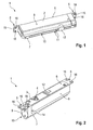
- Fig. 1 and Fig 2 both show different views of a concealed door operator according to an exemplary embodiment of the present invention.
- identical reference numerals denote identical elements.
- the concealed door operator 1 comprises a housing 2, in which an operating unit 3 is provided.
- the operating unit 3 is adapted to operate a door equipped with the concealed door operator 1.
- the concealed door operator 1 can be provided within a cavity of a door leaf.
- the operating unit 3 For operating the door, i.e. for opening or closing the door, the operating unit 3 comprises a square pinion 4, which is the only part of the operating unit 3 being accessible from outside the housing 2.
- the square pinion 4 can be connected to a level arm which is supported on a wall.
- the square pinion 4 When opening or closing the door, the square pinion 4 is rotated and a load is applied to the operating unit 3.
- This energy is stored within the operating unit 3 and can be used for operating the door.
- energy is stored within the operating unit 3 when opening the door such that the concealed door closer 1 can use the stored energy for closing the door.
- the housing 2 of the concealed door operator 1 comprises a top face 6, an opposing bottom face 7 and side faces 8.
- mounting features 5 are provided on the top face 6, mounting features 5 are provided.
- the mounting features 5 comprise flanges 15 and through holes 16 for mounting the concealed door operator 1 on a door leaf or a wall or a floor.
- the concealed door operator 1 is installed within a cavity of the door leaf, while the flanges 15 of the mounting features 5 are disposed on surfaces outside the cavity. Mounting screws can be used for fixing the flanges 15 via the through holes 16 of the mounting features 5.
- the housing 2 is preferably a single cast piece, which can be made from aluminum or iron.
- the housing 2 is very simple to manufacture. Since the mounting features 5 are integrally formed with the housing 2, only a single cast piece has to be manufactured.
- the housing 2 comprises a cavity (not shown), which is provided on the top face 6 and which is covered by a cover plate 12.
- the cover plate 12 can be made from metal such as aluminum or from plastics.
- the housing 2 further comprises stiffening means 10 for providing stability.
- the stiffening means 10 compensates the weakening of the housing 2 due to the above mentioned cavity. Therefore, the stiffening means 10 is provided on the bottom face 7 of the housing 2. Further, the stiffening means 10 extends along a longitudinal direction of the housing 2 and covers substantially the whole lengths of the housing 2. The stiffening means 10 extends at least over on third of the length of the housing 2. Therefore, the housing 2 does not flex or deform even in the case it is subjected to hammer blows during installation of the housing within a door leaf or a floor or a wall.
- the housing joins with a bearing housing feature 17 provided with the housing 2.
- the bearing housing feature 17 supports at least parts of the operating unit 3.
- the stiffening means 10 comprises at least two stiffening ribs 11.
- the stiffening ribs 11 are orientated parallel to each other.
- the housing is produced by pressure die casting. Therefore, the two stiffening ribs 11 allow basically the same support as a single stiffening rib having the same dimensions than the two stiffening ribs 11. Nevertheless, material shrinkage and therefore the porosity of the housing are minimized when forming two stiffening ribs 11.
- the dimension of the stiffening means 10 is calculated and designed with sufficient strength for the housing to withstand hammer blows during installation. In particular, the stiffening ribs 11 extend over the whole lengths of the housing 2.
- the housing comprises an opening 13 for inserting at least parts of the operating unit 3.
- the opening 13 is covered by an end cap which also serves as support for the operating unit 3.
- the operating unit 3 is adapted to store energy when moving the door equipped with the concealed door operator 1 in one direction and is adapted to drive the door in the other direction from the stored energy. At the same time, any movement of the door is damped.
- the operating unit 3 applies pressure to the end cap. Therefore, the end cap is designed to withstand the pressure. Additionally, the housing 2 comprises an enforced wall section 14 around the opening 13. This allows both, the end cap and the housing 2, to withstand the pressure load applied by the operating unit 3.
- the concealed door operator 1 provides several advantages in saving material during the manufacturing process of the concealed door operator 1. Therefore, the concealed door operator 1 is simple to manufacture and low in cost. As evident from the above description, optimal design with the appropriate production process allows for selective stiffness enhancing integrally incorporated to the end product und minimizes part and material usage.
Landscapes
- Power-Operated Mechanisms For Wings (AREA)
- Closing And Opening Devices For Wings, And Checks For Wings (AREA)
Abstract
Description
- The present invention regards concealed door operators. Such door operators are used for providing an opening or closing force to a door.
- In general, concealed door operators are well-known from the prior art. Concealed door operators are hidden within a door leaf or a floor or a wall, such that no visible unit needs to be provided on the door. In case of installation within a door leaf, the door operator is subject to hammer blows when the main arm is assembled to the pinion. Under such blows, the housing could flex and damage the components within the housing.
- It is an object underlying the present invention to provide a low-maintenance concealed door operator which is simple to manufacture and install.
- The solution of this object is achieved by the features of
claim 1. Accordingly, the object is solved by a concealed door operator comprising a housing, an operating unit and stiffening means. The operating unit is provided within the housing and allows opening and/or closing a door equipped with the concealed door operator. The stiffening means is provided on at least one face of the housing. Further, the stiffening means extending substantially over the whole length of the housing in longitudinal direction length. Preferably, the housing has a basically cylindrical shape. In case the concealed door operator is provided within a door leaf, the longitudinal direction is the direction along the width of the door leaf. Any stiffening means extends substantially over the whole length in case the stiffening means extends at least over half the length of the housing, preferably over one third of the length of the housing. Due to such stiffening means, the housing is resistant against hammer blows and deformation according to forces during operation of the door. Preferably, the stiffening means joins with a bearing housing feature of the housing. The bearing housing feature is adapted to support at least parts of the operating unit. - The dependent claims comprise advantageous embodiments of the present invention.
- In a preferred embodiment, the stiffening means comprises at least two parallel stiffening ribs. In particular, both ribs extend over the same length. Compared with a single stiffening rib, the two ribs save material when manufacturing the housing while providing an enhanced stability. The stiffening ribs are calculated and designed with sufficient strength for the housing to withstand the hammering during installation.
- Preferably, the housing comprises a top face and an opposing bottom face. Further, the operating unit particularly comprises a square pinion protruding from the top face and allowing transmittal of torque from or to the operation unit. The stiffening means is provided on the bottom face. With the stiffening means on the bottom face, bending or flex of the housing can be prevented effectively. Therefore, stability of the housing is increased.
- In order to save material, the housing preferably comprises a cavity resulting in a cutout of the top face. In a particular embodiment, the cavity is covered by a cover plate.
- In another preferred embodiment, the top face comprises mounting features for mounting the concealed door operator within a door leaf or a floor. The mounting features can be flanges or boreholes for mounting the concealed door operator. In particular, the mounting features are integrally mounted with the housing.
- The housing particularly comprises an opening for removing and/or inserting at least parts of the operating unit. The opening is preferably covered by an end cap. The end cap is designed to withstand loads applied by the operating unit when moving the door. Further, the housing comprises a reinforced wall section around the opening. This is to enhance the durability of the housing to withstand the pressure loads applied to the end cap. This optimal design with selective stiffness enhancing integrally incorporated to the housing minimizes part and material usage while enhancing the stability and durability of the concealed door operator.
- The concealed door operator is preferably characterized in that the housing is a cast housing. The cast housing can simply be provided with stiffening means or enhanced wall sections as described above. Further, a cast housing is simple to manufacture and low in cost. Nevertheless, the cast housing is designed to provide maximum durability during the lifecycle of the concealed door operator.
- In a preferred embodiment of the concealed door operator, the operating unit is a door closing unit. Therefore, the door can be opened manually and is closed by the concealed door operator. Since the door operator is concealed, there is no visible unit provided on the door such that an esthetic appeal is maintained.
- Preferably, the operating unit comprises an operating piston and a damping piston. Both, the operating piston and the damping piston are engaged with a pinion cam for transforming the longitudinal movement of the pistons into a rotational movement of the pinion cam. With such a design, the concealed door operator can be installed in any door independent from the opening direction of the door. The pinion cam can be rotated clockwise or counterclockwise while in both cases load is provided to the operating unit.
- In another preferred embodiment, the operating unit also comprises an operating piston and a damping piston. The operating piston and the damping piston are connected to a rack with a pinion engaged with the rack for transforming the longitudinal movement of the pistons and the rack into a rotational movement of the pinion. This design allows an installation of the concealed door operator only in doors having a predetermined opening direction. Therefore, the concealed door operator is preferably provided in two versions, in the one version the pinion needs to be rotated clockwise for providing load to the operating unit, in the other version the pinion needs to be rotated counterclockwise for providing load to the operating unit.
- In the following, preferred exemplary embodiments of the invention are explained with reference to the drawings. In the drawings:
- Fig. 1
- is a schematic drawing showing an exemplary embodiment of the concealed door operator according to the invention,
- Fig. 2
- is another schematic drawing showing an exemplary embodiment of the concealed door operator according to the invention.
-
Fig. 1 and Fig 2 both show different views of a concealed door operator according to an exemplary embodiment of the present invention. In both figures, identical reference numerals denote identical elements. - The concealed
door operator 1 comprises ahousing 2, in which anoperating unit 3 is provided. Theoperating unit 3 is adapted to operate a door equipped with the concealeddoor operator 1. In particular, the concealeddoor operator 1 can be provided within a cavity of a door leaf. - For operating the door, i.e. for opening or closing the door, the
operating unit 3 comprises a square pinion 4, which is the only part of theoperating unit 3 being accessible from outside thehousing 2. The square pinion 4 can be connected to a level arm which is supported on a wall. When opening or closing the door, the square pinion 4 is rotated and a load is applied to theoperating unit 3. This energy is stored within theoperating unit 3 and can be used for operating the door. For example, energy is stored within theoperating unit 3 when opening the door such that theconcealed door closer 1 can use the stored energy for closing the door. - The
housing 2 of theconcealed door operator 1 comprises atop face 6, an opposingbottom face 7 and side faces 8. On thetop face 6, mountingfeatures 5 are provided. The mounting features 5 compriseflanges 15 and throughholes 16 for mounting theconcealed door operator 1 on a door leaf or a wall or a floor. In one embodiment, theconcealed door operator 1 is installed within a cavity of the door leaf, while theflanges 15 of the mounting features 5 are disposed on surfaces outside the cavity. Mounting screws can be used for fixing theflanges 15 via the throughholes 16 of the mounting features 5. Thehousing 2 is preferably a single cast piece, which can be made from aluminum or iron. - It can be seen from the figures and the above explanation that the
housing 2 is very simple to manufacture. Since the mounting features 5 are integrally formed with thehousing 2, only a single cast piece has to be manufactured. - The
housing 2 according to the first exemplary embodiment has a generally prismatic shape. The mounting features 5, in particular theflanges 10, are provided on base faces of the prism. This results in a narrow mounting space required for installation of theconcealed door operator 1. - In order to save material, the
housing 2 comprises a cavity (not shown), which is provided on thetop face 6 and which is covered by acover plate 12. Thecover plate 12 can be made from metal such as aluminum or from plastics. - The
housing 2 further comprises stiffening means 10 for providing stability. In particular, the stiffening means 10 compensates the weakening of thehousing 2 due to the above mentioned cavity. Therefore, the stiffening means 10 is provided on thebottom face 7 of thehousing 2. Further, the stiffening means 10 extends along a longitudinal direction of thehousing 2 and covers substantially the whole lengths of thehousing 2. The stiffening means 10 extends at least over on third of the length of thehousing 2. Therefore, thehousing 2 does not flex or deform even in the case it is subjected to hammer blows during installation of the housing within a door leaf or a floor or a wall. Preferably, the housing joins with a bearinghousing feature 17 provided with thehousing 2. The bearinghousing feature 17 supports at least parts of theoperating unit 3. - The stiffening means 10 comprises at least two stiffening
ribs 11. The stiffeningribs 11 are orientated parallel to each other. According to a preferred embodiment, the housing is produced by pressure die casting. Therefore, the two stiffeningribs 11 allow basically the same support as a single stiffening rib having the same dimensions than the two stiffeningribs 11. Nevertheless, material shrinkage and therefore the porosity of the housing are minimized when forming two stiffeningribs 11. The dimension of the stiffening means 10 is calculated and designed with sufficient strength for the housing to withstand hammer blows during installation. In particular, the stiffeningribs 11 extend over the whole lengths of thehousing 2. - Applying the above mentioned stiffening means 10 reduces material usage as well as minimizes porosity in the housing. The grade of material for the housing was also selected for wear resistance against a sliding piston made of steel. Therefore in this
concealed door operator 1, there is no need for additional hard anodizing process. Additionally, no separate mounting plate needs to be provided since the mounting features 5 are integrally formed with thehousing 2. - As can be seen especially from
figure 2 , the housing comprises anopening 13 for inserting at least parts of theoperating unit 3. Theopening 13 is covered by an end cap which also serves as support for theoperating unit 3. Theoperating unit 3 is adapted to store energy when moving the door equipped with theconcealed door operator 1 in one direction and is adapted to drive the door in the other direction from the stored energy. At the same time, any movement of the door is damped. - During operation, the operating unit 3applies pressure to the end cap. Therefore, the end cap is designed to withstand the pressure. Additionally, the
housing 2 comprises an enforcedwall section 14 around theopening 13. This allows both, the end cap and thehousing 2, to withstand the pressure load applied by theoperating unit 3. - It can be seen from the above that the exemplary embodiments of the
concealed door operator 1 that the invention provides several advantages in saving material during the manufacturing process of theconcealed door operator 1. Therefore, theconcealed door operator 1 is simple to manufacture and low in cost. As evident from the above description, optimal design with the appropriate production process allows for selective stiffness enhancing integrally incorporated to the end product und minimizes part and material usage. -
- 1
- concealed door operator
- 2
- housing
- 3
- operating unit
- 4
- square pinion
- 5
- mounting feature
- 6
- top face
- 7
- bottom face
- 8
- side face
- 9
- end cap
- 10
- stiffening means
- 11
- stiffening rib
- 12
- cover plate
- 13
- opening
- 14
- reinforced wall section
- 15
- flange
- 16
- through hole
- 17
- bearing housing feature
Claims (10)
- Concealed door operator (1), comprising- a housing (2),- an operating unit (3) provided within the housing (2), and- stiffening means (10) provided on at least one face (6, 7, 8) of the housing (2), and extending substantially over the whole length of the housing (2) in longitudinal direction.
- Concealed door operator (1) according to claim 1, characterized in that stiffening means (10) comprises at least two parallel stiffening ribs (11).
- Concealed door operator (1) according to claims 1 to 3, characterized in that the housing (2) comprises a top face (6) and an opposing bottom face (7), and the operating unit comprises a square pinion (4) protruding from the top face (6) and allowing transmittal of torque from or to the operation unit, wherein the stiffening means (10) is provided on the bottom face (7).
- Concealed door operator (1) according to claim 3, characterized in that the housing (2) comprises a cavity resulting in a cutout of the top face (6).
- Concealed door operator (1) according to claims 3 or 4, characterized in that the top face (6) comprises mounting features (5) for mounting the concealed door operator within a door leaf or a floor or a wall.
- Concealed door operator (1) according to claims 1 to 5, characterized in that the housing (2) comprises an opening (13) for removing and/or inserting at least parts of the operating unit (3), and a reinforced wall section (14) around the opening (13).
- Concealed door operator (1) according to claims 1 to 6, characterized in that the housing (2) is a cast housing.
- Concealed door operator (1) according to one of the claims 1 to 7, characterized in that the operating unit (3) is a door closing unit.
- Concealed door operator (1) according to one of the claims 1 to 8, characterized in that the operating unit (3) comprises an operating piston and a damping piston, wherein the operating piston and the damping piston are engaged with a pinion cam for transforming the longitudinal movement of the pistons into a rotational movement of the pinion cam.
- Concealed door operator (1) according to one of the claims 1 to 9, characterized in that the operating unit (3) comprises an operating piston and a damping piston, wherein the operating piston and the damping piston are connected to a rack with a pinion engaged with the rack for transforming the longitudinal movement of the pistons and the rack into a rotational movement of the pinion.
Priority Applications (3)
| Application Number | Priority Date | Filing Date | Title |
|---|---|---|---|
| EP14003056.0A EP2993295A1 (en) | 2014-09-04 | 2014-09-04 | Concealed door operator |
| CN201420688679.3U CN204677036U (en) | 2014-09-04 | 2014-10-21 | Hidden door controller |
| CN201410654335.5A CN105604431A (en) | 2014-09-04 | 2014-10-21 | Concealed door controller |
Applications Claiming Priority (1)
| Application Number | Priority Date | Filing Date | Title |
|---|---|---|---|
| EP14003056.0A EP2993295A1 (en) | 2014-09-04 | 2014-09-04 | Concealed door operator |
Publications (1)
| Publication Number | Publication Date |
|---|---|
| EP2993295A1 true EP2993295A1 (en) | 2016-03-09 |
Family
ID=51690175
Family Applications (1)
| Application Number | Title | Priority Date | Filing Date |
|---|---|---|---|
| EP14003056.0A Withdrawn EP2993295A1 (en) | 2014-09-04 | 2014-09-04 | Concealed door operator |
Country Status (2)
| Country | Link |
|---|---|
| EP (1) | EP2993295A1 (en) |
| CN (2) | CN105604431A (en) |
Citations (4)
| Publication number | Priority date | Publication date | Assignee | Title |
|---|---|---|---|---|
| GB1011032A (en) * | 1962-06-29 | 1965-11-24 | John Irwin Adams | Improvements in or relating to single acting door closing and checking devices |
| GB1282714A (en) * | 1968-08-01 | 1972-07-26 | Armstrong Patents Co Ltd | Improvements in or relating to door closers |
| GB2349173A (en) * | 1999-04-21 | 2000-10-25 | Schlage Lock Co | Door closer |
| EP1431494A2 (en) * | 2002-12-17 | 2004-06-23 | GEZE GmbH | Drive for a wing of a door or window |
-
2014
- 2014-09-04 EP EP14003056.0A patent/EP2993295A1/en not_active Withdrawn
- 2014-10-21 CN CN201410654335.5A patent/CN105604431A/en active Pending
- 2014-10-21 CN CN201420688679.3U patent/CN204677036U/en not_active Expired - Lifetime
Patent Citations (4)
| Publication number | Priority date | Publication date | Assignee | Title |
|---|---|---|---|---|
| GB1011032A (en) * | 1962-06-29 | 1965-11-24 | John Irwin Adams | Improvements in or relating to single acting door closing and checking devices |
| GB1282714A (en) * | 1968-08-01 | 1972-07-26 | Armstrong Patents Co Ltd | Improvements in or relating to door closers |
| GB2349173A (en) * | 1999-04-21 | 2000-10-25 | Schlage Lock Co | Door closer |
| EP1431494A2 (en) * | 2002-12-17 | 2004-06-23 | GEZE GmbH | Drive for a wing of a door or window |
Also Published As
| Publication number | Publication date |
|---|---|
| CN204677036U (en) | 2015-09-30 |
| CN105604431A (en) | 2016-05-25 |
Similar Documents
| Publication | Publication Date | Title |
|---|---|---|
| US9003605B2 (en) | Furniture hinge with incorporated wing having linear and rotary movement | |
| US20130067689A1 (en) | Hinge | |
| US10526825B2 (en) | Cabinet assembly | |
| KR20150056803A (en) | Motor vehicle door lock | |
| US20060059662A1 (en) | Projection reinforced, five knuckle, hospital tip overlay hinge | |
| JP2016089546A (en) | Sliding door for locking device | |
| US20160097226A1 (en) | Door Frames with Energy Absorbing Door Stops | |
| CN204677036U (en) | Hidden door controller | |
| KR101265157B1 (en) | Aluminium hinge | |
| EP2993293A1 (en) | Concealed door operator | |
| JP6503232B2 (en) | Electrical equipment storage box | |
| EP2993294A1 (en) | Concealed door operator | |
| PT1431494E (en) | Drive for a wing of a door or window | |
| EP2903927B1 (en) | Chain shackle | |
| CN204457233U (en) | Hidden door controller | |
| EP2778320B1 (en) | Reinforcement part for lock case | |
| RU2562032C2 (en) | Carrier opening part lock and rotary lug | |
| JP4396991B2 (en) | cabinet | |
| CN107700990B (en) | Hook lock reinforcing device | |
| KR20180000145U (en) | A Door Locking Assembly | |
| EP3626904B1 (en) | A roof window with an improved lock casing | |
| JP2005118125A (en) | Locking apparatus for game machine | |
| EP1310617A2 (en) | Striker plate installation | |
| EP3159468B1 (en) | Fastening system for overhead doors | |
| KR200459373Y1 (en) | A hinge fixture for door |
Legal Events
| Date | Code | Title | Description |
|---|---|---|---|
| PUAI | Public reference made under article 153(3) epc to a published international application that has entered the european phase |
Free format text: ORIGINAL CODE: 0009012 |
|
| AK | Designated contracting states |
Kind code of ref document: A1 Designated state(s): AL AT BE BG CH CY CZ DE DK EE ES FI FR GB GR HR HU IE IS IT LI LT LU LV MC MK MT NL NO PL PT RO RS SE SI SK SM TR |
|
| AX | Request for extension of the european patent |
Extension state: BA ME |
|
| 17P | Request for examination filed |
Effective date: 20160909 |
|
| RBV | Designated contracting states (corrected) |
Designated state(s): AL AT BE BG CH CY CZ DE DK EE ES FI FR GB GR HR HU IE IS IT LI LT LU LV MC MK MT NL NO PL PT RO RS SE SI SK SM TR |
|
| STAA | Information on the status of an ep patent application or granted ep patent |
Free format text: STATUS: REQUEST FOR EXAMINATION WAS MADE |
|
| STAA | Information on the status of an ep patent application or granted ep patent |
Free format text: STATUS: THE APPLICATION IS DEEMED TO BE WITHDRAWN |
|
| 18D | Application deemed to be withdrawn |
Effective date: 20160910 |