EP2993021B1 - Core box and method for producing hollow structure - Google Patents
Core box and method for producing hollow structure Download PDFInfo
- Publication number
- EP2993021B1 EP2993021B1 EP14842876.6A EP14842876A EP2993021B1 EP 2993021 B1 EP2993021 B1 EP 2993021B1 EP 14842876 A EP14842876 A EP 14842876A EP 2993021 B1 EP2993021 B1 EP 2993021B1
- Authority
- EP
- European Patent Office
- Prior art keywords
- mandrel
- assembled
- hollow structure
- prepreg
- mandrel member
- Prior art date
- Legal status (The legal status is an assumption and is not a legal conclusion. Google has not performed a legal analysis and makes no representation as to the accuracy of the status listed.)
- Not-in-force
Links
Images



Classifications
-
- B—PERFORMING OPERATIONS; TRANSPORTING
- B29—WORKING OF PLASTICS; WORKING OF SUBSTANCES IN A PLASTIC STATE IN GENERAL
- B29C—SHAPING OR JOINING OF PLASTICS; SHAPING OF MATERIAL IN A PLASTIC STATE, NOT OTHERWISE PROVIDED FOR; AFTER-TREATMENT OF THE SHAPED PRODUCTS, e.g. REPAIRING
- B29C33/00—Moulds or cores; Details thereof or accessories therefor
- B29C33/44—Moulds or cores; Details thereof or accessories therefor with means for, or specially constructed to facilitate, the removal of articles, e.g. of undercut articles
- B29C33/48—Moulds or cores; Details thereof or accessories therefor with means for, or specially constructed to facilitate, the removal of articles, e.g. of undercut articles with means for collapsing or disassembling
- B29C33/485—Moulds or cores; Details thereof or accessories therefor with means for, or specially constructed to facilitate, the removal of articles, e.g. of undercut articles with means for collapsing or disassembling cores or mandrels
-
- B—PERFORMING OPERATIONS; TRANSPORTING
- B29—WORKING OF PLASTICS; WORKING OF SUBSTANCES IN A PLASTIC STATE IN GENERAL
- B29C—SHAPING OR JOINING OF PLASTICS; SHAPING OF MATERIAL IN A PLASTIC STATE, NOT OTHERWISE PROVIDED FOR; AFTER-TREATMENT OF THE SHAPED PRODUCTS, e.g. REPAIRING
- B29C33/00—Moulds or cores; Details thereof or accessories therefor
- B29C33/44—Moulds or cores; Details thereof or accessories therefor with means for, or specially constructed to facilitate, the removal of articles, e.g. of undercut articles
- B29C33/48—Moulds or cores; Details thereof or accessories therefor with means for, or specially constructed to facilitate, the removal of articles, e.g. of undercut articles with means for collapsing or disassembling
-
- B—PERFORMING OPERATIONS; TRANSPORTING
- B29—WORKING OF PLASTICS; WORKING OF SUBSTANCES IN A PLASTIC STATE IN GENERAL
- B29C—SHAPING OR JOINING OF PLASTICS; SHAPING OF MATERIAL IN A PLASTIC STATE, NOT OTHERWISE PROVIDED FOR; AFTER-TREATMENT OF THE SHAPED PRODUCTS, e.g. REPAIRING
- B29C33/00—Moulds or cores; Details thereof or accessories therefor
- B29C33/76—Cores
-
- B—PERFORMING OPERATIONS; TRANSPORTING
- B29—WORKING OF PLASTICS; WORKING OF SUBSTANCES IN A PLASTIC STATE IN GENERAL
- B29C—SHAPING OR JOINING OF PLASTICS; SHAPING OF MATERIAL IN A PLASTIC STATE, NOT OTHERWISE PROVIDED FOR; AFTER-TREATMENT OF THE SHAPED PRODUCTS, e.g. REPAIRING
- B29C43/00—Compression moulding, i.e. applying external pressure to flow the moulding material; Apparatus therefor
- B29C43/02—Compression moulding, i.e. applying external pressure to flow the moulding material; Apparatus therefor of articles of definite length, i.e. discrete articles
- B29C43/10—Isostatic pressing, i.e. using non-rigid pressure-exerting members against rigid parts or dies
- B29C43/12—Isostatic pressing, i.e. using non-rigid pressure-exerting members against rigid parts or dies using bags surrounding the moulding material or using membranes contacting the moulding material
-
- B—PERFORMING OPERATIONS; TRANSPORTING
- B29—WORKING OF PLASTICS; WORKING OF SUBSTANCES IN A PLASTIC STATE IN GENERAL
- B29C—SHAPING OR JOINING OF PLASTICS; SHAPING OF MATERIAL IN A PLASTIC STATE, NOT OTHERWISE PROVIDED FOR; AFTER-TREATMENT OF THE SHAPED PRODUCTS, e.g. REPAIRING
- B29C43/00—Compression moulding, i.e. applying external pressure to flow the moulding material; Apparatus therefor
- B29C43/32—Component parts, details or accessories; Auxiliary operations
- B29C43/36—Moulds for making articles of definite length, i.e. discrete articles
-
- B—PERFORMING OPERATIONS; TRANSPORTING
- B29—WORKING OF PLASTICS; WORKING OF SUBSTANCES IN A PLASTIC STATE IN GENERAL
- B29C—SHAPING OR JOINING OF PLASTICS; SHAPING OF MATERIAL IN A PLASTIC STATE, NOT OTHERWISE PROVIDED FOR; AFTER-TREATMENT OF THE SHAPED PRODUCTS, e.g. REPAIRING
- B29C70/00—Shaping composites, i.e. plastics material comprising reinforcements, fillers or preformed parts, e.g. inserts
- B29C70/04—Shaping composites, i.e. plastics material comprising reinforcements, fillers or preformed parts, e.g. inserts comprising reinforcements only, e.g. self-reinforcing plastics
- B29C70/28—Shaping operations therefor
- B29C70/30—Shaping by lay-up, i.e. applying fibres, tape or broadsheet on a mould, former or core; Shaping by spray-up, i.e. spraying of fibres on a mould, former or core
- B29C70/34—Shaping by lay-up, i.e. applying fibres, tape or broadsheet on a mould, former or core; Shaping by spray-up, i.e. spraying of fibres on a mould, former or core and shaping or impregnating by compression, i.e. combined with compressing after the lay-up operation
- B29C70/342—Shaping by lay-up, i.e. applying fibres, tape or broadsheet on a mould, former or core; Shaping by spray-up, i.e. spraying of fibres on a mould, former or core and shaping or impregnating by compression, i.e. combined with compressing after the lay-up operation using isostatic pressure
-
- B—PERFORMING OPERATIONS; TRANSPORTING
- B29—WORKING OF PLASTICS; WORKING OF SUBSTANCES IN A PLASTIC STATE IN GENERAL
- B29C—SHAPING OR JOINING OF PLASTICS; SHAPING OF MATERIAL IN A PLASTIC STATE, NOT OTHERWISE PROVIDED FOR; AFTER-TREATMENT OF THE SHAPED PRODUCTS, e.g. REPAIRING
- B29C33/00—Moulds or cores; Details thereof or accessories therefor
- B29C33/0038—Moulds or cores; Details thereof or accessories therefor with sealing means or the like
-
- B—PERFORMING OPERATIONS; TRANSPORTING
- B29—WORKING OF PLASTICS; WORKING OF SUBSTANCES IN A PLASTIC STATE IN GENERAL
- B29C—SHAPING OR JOINING OF PLASTICS; SHAPING OF MATERIAL IN A PLASTIC STATE, NOT OTHERWISE PROVIDED FOR; AFTER-TREATMENT OF THE SHAPED PRODUCTS, e.g. REPAIRING
- B29C33/00—Moulds or cores; Details thereof or accessories therefor
- B29C33/56—Coatings, e.g. enameled or galvanised; Releasing, lubricating or separating agents
-
- B—PERFORMING OPERATIONS; TRANSPORTING
- B29—WORKING OF PLASTICS; WORKING OF SUBSTANCES IN A PLASTIC STATE IN GENERAL
- B29K—INDEXING SCHEME ASSOCIATED WITH SUBCLASSES B29B, B29C OR B29D, RELATING TO MOULDING MATERIALS OR TO MATERIALS FOR MOULDS, REINFORCEMENTS, FILLERS OR PREFORMED PARTS, e.g. INSERTS
- B29K2105/00—Condition, form or state of moulded material or of the material to be shaped
- B29K2105/06—Condition, form or state of moulded material or of the material to be shaped containing reinforcements, fillers or inserts
- B29K2105/08—Condition, form or state of moulded material or of the material to be shaped containing reinforcements, fillers or inserts of continuous length, e.g. cords, rovings, mats, fabrics, strands or yarns
- B29K2105/0872—Prepregs
-
- B—PERFORMING OPERATIONS; TRANSPORTING
- B29—WORKING OF PLASTICS; WORKING OF SUBSTANCES IN A PLASTIC STATE IN GENERAL
- B29L—INDEXING SCHEME ASSOCIATED WITH SUBCLASS B29C, RELATING TO PARTICULAR ARTICLES
- B29L2022/00—Hollow articles
Definitions
- the present invention relates to an assembled mandrel used when producing a longitudinally oriented hollow structure using a prepreg, and a method for producing a hollow structure.
- JP 2011-11477A discloses a method for forming a hollow structure having a shape similar to that of an assembled mandrel by layering (winding) a prepreg on the surface of the longitudinally oriented assembled mandrel, covering the assembled mandrel with a vacuum bag, and heating while vacuuming the inside of the vacuum bag, thereby heat-curing the prepreg while pressing the prepreg against the assembled mandrel.
- this forming method as a method of easily withdrawing the assembled mandrel from the formed hollow structure after the forming is completed and the prepreg is cured, as is illustrated in Fig. 6 of this document, there is a method of providing the assembled mandrel having a structure capable of being split into three pieces including an upper mandrel, a center mandrel, and a lower mandrel in advance, and first pulling out the center mandrel and then detaching and withdrawing the upper mandrel and the lower mandrel from inner wall surfaces of the hollow structure.
- JP S63-41131A discloses a core member for forming a hollow FRP square bar, wherein the core member is constituted by three sheets of stainless steel which are superposed with each other and a grease is coated on the contacting surfaces of the sheets in order to facilitate, after a molded form formed by laminating prepregs on and around the core member is released from a mold, pulling out of the central sheet of the core member followed by removing by extracting the remaining two sheets.
- WO 2005/105402A discloses a mandrel for forming co-cured stringers, wherein the mandrel is to be placed in a channel or recess of a preformed uncured stringer and removed after curing.
- the mandrel is made from an elastomeric material and has a shape that substantially conforms to the corresponding channel defined by the stringer.
- the mandrel has an opening into which plural elongated strips made of a polymeric material can be inserted to reinforce the mandrel. After curing of the stringer the strips can be individually pulled out from the opening of the mandrel, which in return can collapse and can be removed from the channel of the stringer, too.
- JP 2011-11474A discloses the use of release films to facilitate the removal of split type mandrels.
- the prepreg is formed in accordance with the shape of the assembled mandrel while being pressed and heated as described above, the melted or softened resin material of the prepreg enters the mating surfaces of the assembled mandrel due to the pressure at the time of the forming. For this reason, there is a problem in that the thickness of the completed hollow structure decreases or that quality, such as the precision of dimensions, deteriorates.
- the invention has been made in view of such a situation, and an object thereof is to provide an assembled mandrel and a method for producing a hollow structure that can easily withdraw the split-type assembled mandrel after forming of the assembled mandrel, can enhance the durability of the assembled mandrel, and can prevent a situation in which resin enters the contact surfaces of the assembled mandrel and the thickness of the hollow structure decreases.
- the invention provides an assembled mandrel for forming a hollow structure as defined by claim 1 and a method for producing a hollow structure as defined by claim 3.
- the assembled mandrel includes a first mandrel member that extends in a longitudinal direction; a second mandrel member that extends in the longitudinal direction, is adjacent to the first mandrel member, and is separated from the first mandrel member and withdrawn in the longitudinal direction after the forming of the hollow structure; and a planar detachable member that is disposed to cover at least one surface of facing contact surfaces between the first mandrel member and the second mandrel member.
- the second mandrel member can be easily detached and withdrawn from the first mandrel member after the forming of the hollow structure.
- the workability when the second mandrel member and further the entire assembled mandrel are withdrawn from the hollow structure can be enhanced, the contact surfaces between the first mandrel member and the second mandrel member can be prevented from being damaged or worn out, and the durability of the assembled mandrel can be enhanced.
- the detachable member covering the contact surfaces between the first mandrel member and the second mandrel member is easily replaced even if damaged, the condition of the assembled mandrel can be soundly kept for a prolonged period of time.
- the contact surfaces between the first mandrel member and the second mandrel member are liquid-tightly sealed.
- a plurality of the detachable members are formed in the shape of a strip and perform covering in parallel so as to extend in the longitudinal direction, and empty spaces that extend in the longitudinal direction are provided between the respective detachable members.
- the area when the detachable members come into close contact with the contact surfaces between the first mandrel member and the second mandrel member decreases markedly. For this reason, the frictional resistance when the second mandrel member is detached and withdrawn from the first mandrel member can be made smaller, and the second mandrel member can be easily withdrawn.
- resin strips made of the same kind of resin material as the prepreg may be adhered to the empty spaces via a mandrel-releasing agent.
- the resin strips made of the same kind of resin material as the prepreg are sandwiched between the first mandrel member and the second mandrel member adjacent thereto, together with the detachable members. Accordingly, when the hollow structure is formed while being pressed and heated, the resin strips become soft due to heat, and the softened resin material swells toward the prepreg that forms the hollow structure due to the pressure of the pressing from between the first mandrel member and the second mandrel member (the contact surfaces), and the resin material of the prepreg is replenished.
- the resin material to form the prepreg enters a space between the first mandrel member and the second mandrel member and the thickness of the completed hollow structure decreases or in which quality, such as the precision of dimensions, deteriorates.
- the resin strips are interposed between the first mandrel member and the second mandrel member via the mandrel-releasing agent. For this reason, the effect of making the first mandrel member and the second mandrel member be easily detached from each other is exhibited similar to the detachable members.
- the mandrel includes a first mandrel member that extends in a longitudinal direction; a second mandrel member that extends in the longitudinal direction, is adjacent to the first mandrel member, and is separated from the first mandrel member and withdrawn in the longitudinal direction after the forming of the hollow structure; and a resin strip that is sandwiched between the first mandrel member and the second mandrel member via a mandrel-releasing agent, extends in the longitudinal direction, and is made of the same kind of resin material as the prepreg.
- the first mandrel member and the second mandrel member are easily detached from each other due to the mandrel-releasing agent interposed between each mandrel member and the resin strips, and the first mandrel member and the second mandrel member after the forming of the hollow structure are easily withdrawn from each other.
- the workability when the assembled mandrel is withdrawn from the hollow structure can be enhanced, and the resin strips are interposed between the first mandrel member and the second mandrel member. Accordingly, the contact surfaces between the first mandrel member and the second mandrel member can be prevented from being damaged or worn out when the second mandrel member is withdrawn, and the durability of the assembled mandrel can be enhanced.
- the resin strips become soft due to heat, and the softened resin material swells toward the prepreg that forms the hollow structure due to the pressure of the pressing from between the first mandrel member and the second mandrel member (the contact surfaces), and the resin material of the prepreg is replenished.
- the method for producing a hollow structure includes a detachable member covering step of covering at least one surface of facing contact surfaces between a first mandrel member that constitutes the assembled mandrel and extends in a longitudinal direction and a second mandrel member that extends in the longitudinal direction and is adjacent to the first mandrel member, with a detachable member; a mandrel assembling step of overlapping the first mandrel member and the second mandrel member on each other, thereby assembling the assembled mandrel; a prepreg layering step of layering the prepreg on the surface of the assembled mandrel; a forming step of covering the assembled mandrel, on which the prepreg has been layered, with the vacuum bag, and heating while vacuuming the inside of the vacuum bag; and a mandrel withdrawing step of separating the second mandrel member of the assembled mandrel from the first mandrel member to detach the second mandrel member in the longitudinal direction, and
- the second mandrel member can be easily detached from the first mandrel member and withdrawn in the longitudinal direction.
- the workability when the assembled mandrel is withdrawn after the forming of the hollow structure can be enhanced, the contact surfaces between the first mandrel member and the second mandrel member can be prevented from being damaged or worn out, and the durability of the assembled mandrel can be enhanced.
- the split-type assembled mandrel can be easily withdrawn after the forming of the hollow structure, the durability of the assembled mandrel can be enhanced, and a situation in which resin enters the contact surfaces of the assembled mandrel and the thickness of the hollow structure decreases can be prevented.
- Fig. 1 is a perspective view of an assembled mandrel 11 illustrating an example serving to explain features of the invention.
- the assembled mandrel 11 is used in order to form a longitudinally oriented hollow structure S, such as a rotor blade of a helicopter, using a prepreg P.
- the assembled mandrel is used for performing the so-called autoclave forming in which the hollow structure S having a shape (a shape along) similar to that of the assembled mandrel 11 is formed by layering (winding) the prepreg P on the surface of the assembled mandrel 11, covering the assembled mandrel with a vacuum bag V as will be described below, and hot-forming while vacuuming the inside of the vacuum bag V, thereby heat-curing the prepreg P while pressing the prepreg P against an outer peripheral surface of the assembled mandrel 11. Then, after this autoclave forming, the assembled mandrel 11 is withdrawn from the hollow structure S and the hollow structure S is completed.
- the assembled mandrel 11 is equipped with two outer mandrel members 2 (first mandrel members) that extend in a longitudinal direction, and a center mandrel member 3 (second mandrel member) that is sandwiched between the outer mandrel members 2.
- the center mandrel member 3 is capable of being withdrawn in the longitudinal direction from between the two outer mandrel members 2 after the forming of the hollow structure S.
- a tape 5 (detachable member) formed of a low-friction material is adhered to at least one surface of the facing contact surfaces between the two outer mandrel members 2 and the center mandrel member 3.
- the tapes 5 are respectively adhered to both surfaces of the center mandrel member 3 in the present embodiment, the tapes 5 may be respectively adhered to the outer mandrel members 2 or may be respectively adhered to both of the outer mandrel members 2 and the center mandrel member 3.
- Fluororesin-based materials such as polytetrafluoroethylene (registered trademark: Teflon), are preferable as materials for the tapes 5.
- Teflon polytetrafluoroethylene
- other materials such as polypropylene, polyarylate, diacetylcellulose, triacetylcellulose, acetylcellulose butylate, silicone-based resins, and alkyd-based resins, are also considered.
- films made of the above respective materials, films that are coated with the above respective materials, or the like may be used instead of using the adhesive tapes 5 as the detachable members.
- the tapes 5 are respectively adhered to both surfaces (contact surfaces) of the center mandrel member 3 that constitutes the assembled mandrel 11 (detachable member covering step A).
- the tapes 5 may be respectively adhered to the contact surfaces of the outer mandrel members 2 instead of being adhered to both the surfaces of the center mandrel member 3.
- the assembled mandrel 11 is assembled by overlapping the two outer mandrel members 2 on the center mandrel member 3 having the tapes 5 adhered to both the surfaces thereof, respectively, (mandrel assembling step B).
- a mandrel-releasing agent is coated between the tapes 5 and the outer mandrel members 2, this is more preferable.
- the prepreg P is layered on the surface of the assembled mandrel 11 (prepreg layering step C).
- the hollow structure S is completed. Thereafter, the assembled mandrel 11 is withdrawn together with the hollow structure S from the vacuum bag V.
- the center mandrel member 3 of the assembled mandrel 11 is detached from between the two outer mandrel members 2 and is withdrawn in the longitudinal direction, and thereafter, as illustrated on the right side of Fig. 2(e) , the two outer mandrel members 2 are withdrawn from the hollow structure S (mandrel withdrawing step E).
- the two outer mandrel members 2 can be easily withdrawn from the hollow structure S. Accordingly, the hollow structure S is completed.
- the tapes 5 formed of a low-friction material such as fluororesin, are respectively interposed between the facing contact surfaces between the two outer mandrel members 2 and the center mandrel member 3 sandwiched therebetween. Accordingly, the frictional coefficient between the outer mandrel members 2 and the center mandrel member 3 becomes small, and the outer mandrel members 2 and the center mandrel member 3 are easily detached from each other.
- the mandrel withdrawing step E when the center mandrel member 3 is first withdrawn from between the two outer mandrel members 2 in the longitudinal direction, it is very easy to withdraw the center mandrel member 3. For this reason, the workability when the center mandrel member 3 is withdrawn can be markedly enhanced, the contact surfaces between the outer mandrel members 2 and the center mandrel member 3 can be prevented from being damaged or worn out, and the durability of the assembled mandrel 11 can be rapidly enhanced.
- the condition of the assembled mandrel 11 can be soundly kept for a prolonged period of time by replacing the tapes 5 periodically.
- the portions between the outer mandrel members 2 and the center mandrel member 3 are liquid-tightly sealed.
- the prepreg P is formed in accordance with the shape of the assembled mandrel 11 while being pressed and heated inside the vacuum bag V, the melted or softened resin material of the prepreg P enters splitting surfaces of the assembled mandrel 11 due to the pressure at the time of the forming. For this reason, the thickness of the completed hollow structure S can be prevented from decreasing and precision can be prevented from degrading.
- Fig. 3 is a perspective view of an assembled mandrel 21 illustrating a first embodiment of the invention.
- the tapes 5 formed of a low-friction material similar to the example are respectively adhered to both surfaces of the center mandrel member 3 that constitutes the assembled mandrel 21.
- a plurality of the tapes 5 extend in the longitudinal direction and are adhered in parallel to each surface, and a plurality of empty spaces 6 that extend in the longitudinal direction are provided between these respective tapes 5.
- the other components are the same as those of the example.
- the width dimension of the plurality of tapes 5 is 10 mm, and the width dimension of the empty spaces 6 is also 10 mm.
- the number of the tapes 5 and the width dimensions of the tapes 5 and the empty spaces 6 can be appropriately changed according to the dimension of the hollow structure S.
- the width dimensions of the tapes 5 and the empty spaces 6 are not necessarily the same dimensions altogether.
- the tapes 5 may be respectively adhered to the bonding surfaces of the outer mandrel members 2 instead of being adhered to both the surfaces of the center mandrel member 3.
- the areas of the tapes 5 that come into close contact with the outer mandrel members 2 (or the center mandrel member 3) are markedly reduced by adhering the plurality of tapes 5 at predetermined intervals to each of both surfaces (or the bonding surfaces of the outer mandrel members 2) of the center mandrel member 3, and providing the empty spaces 6 between the tapes.
- the frictional resistance when the center mandrel member 3 is withdrawn from between the outer mandrel members 2 can be made smaller than that in the case of the example, and the center mandrel member 3 can be more easily withdrawn from between the outer mandrel members 2 after the completion of the forming.
- the amount of the tape members 5 to be used can be reduced, and a reduction in cost can be achieved.
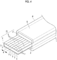
- Fig. 4 is a perspective view of an assembled mandrel 31 illustrating a second embodiment of the invention.
- the plurality of tapes 5 formed of a low-friction material similar to the first embodiment are respectively adhered to both surfaces of the center mandrel member 3 that constitutes the assembled mandrel 31, and the plurality of empty spaces 6 are provided between these respective tapes 5.
- a plurality of resin strips 7 are adhered to the empty spaces 6 via the mandrel-releasing agent.
- the resin strips 7 are made of the same kind of resin material as the prepreg P, and are formed in the shape of a strip. In addition, the resin strips 7 may not include strengthening fibers. It is preferable to set the thickness of the resin strips 7 to be equal to the thickness of the tapes 5. Additionally, the width of the resin strips 7 is set to be equal to or slightly smaller than the width of the empty spaces 6. The other components are the same as those of the first embodiment.
- the plurality of tapes 5 are adhered at predetermined intervals to each of both surfaces (or the bonding surfaces of the outer mandrel members 2) of the center mandrel member 3, and the resin strips 7 made of the same kind of resin material as the prepreg P and formed in the shape of a strip are respectively adhered to the empty spaces 6 between the tapes via the mandrel-releasing agent. Accordingly, the resin strips 7 are sandwiched together with the tapes 5 between the two outer mandrel members 2 and the center mandrel member 3 (the contact surfaces).
- the resin strips 7 become soft due to heat, and the softened resin material swells toward the prepreg P that forms the hollow structure S due to the pressure of the pressing from between the outer mandrel members 2 and the center mandrel member 3 (the contact surfaces), and the resin material of the prepreg P is replenished.
- the resin material of the softened resin strips 7 may be made to swell toward the prepreg P more positively by making the resin strips 7 thicker than the tapes 5.
- the resin material to form the prepreg P enters spaces between the outer mandrel members 2 and the center mandrel member 3 and the thickness of the completed hollow structure S decreases or in which the precision degrades.
- the resin strips 7 are interposed between the outer mandrel members 2 and the center mandrel member 3 via the mandrel-releasing agent. For this reason, the effect of making the outer mandrel members 2 and the center mandrel member 3 be easily detached from each other is exhibited similar to the tapes 5.
- Fig. 5 is a perspective view of an assembled mandrel 41 illustrating a third embodiment of the invention.
- resin strips 8 made of the same kind of resin material as the prepreg P are respectively sandwiched between the two outer mandrel members 2 and the center mandrel member 3 that constitute the assembled mandrel 41 via the mandrel-releasing agent, and the tapes 5 of the example and the first to second embodiments are not used.
- the width of the resin strips 8 are set to be substantially equal to the width of the assembled mandrel 41 (the outer mandrel members 2 and the center mandrel member 3).
- the workability when the center mandrel member 3 is withdrawn can be enhanced, the contact surfaces between the outer mandrel members 2 and the center mandrel member 3 can be prevented from being damaged or worn out with the withdrawal of the center mandrel member 3, and the durability of the assembled mandrel 41 can be enhanced.
- the center mandrel member 3 can be easily withdrawn after the forming of the hollow structure S between the outer mandrel members 2 of the split-type assembled mandrels 11, 21, 31, and 41, the durability of the assembled mandrels 11, 21, 31, and 41 can be enhanced, it is possible to prevent a situation in which the resin of the prepreg P flows backward to the contact surfaces between the outer mandrel members 2 and the center mandrel member 3 and the thickness of the hollow structure S decreases, and quality, such as the precision of dimensions, can be enhanced.
- the shapes or split structures of the assembled mandrels 11, 21, 31, and 41 are not limited to those of the above embodiments. That is, although the assembled mandrels 11, 21, 31, and 41 in the respective embodiments have an upward-downward three-piece split structure in which the one center mandrel member 3 is sandwiched between the two outer mandrel members 2, it is also considered that the assembled mandrels have an upward-downward two-piece split structure, a leftward-rightward three-piece split (a leftward-rightward two-piece split) structure, or the like.
- the mandrel withdrawing step E when the center mandrel member 3 is first withdrawn from between the two outer mandrel members 2 in the longitudinal direction, it is very easy to withdraw the center mandrel member 3. For this reason, the workability when the center mandrel member 3 is withdrawn can be markedly enhanced, the contact surfaces between the outer mandrel members 2 and the center mandrel member 3 can be prevented from being damaged or worn out, and the durability of the assembled mandrel 11 can be rapidly enhanced.
- the condition of the assembled mandrel 11 can be soundly kept for a prolonged period of time by replacing the tapes 5 periodically.
- the portions between the outer mandrel members 2 and the center mandrel member 3 are liquid-tightly sealed.
- the prepreg P is formed in accordance with the shape of the assembled mandrel 11 while being pressed and heated inside the vacuum bag V, the melted or softened resin material of the prepreg P enters splitting surfaces of the assembled mandrel 11 due to the pressure at the time of the forming. For this reason, the thickness of the completed hollow structure S can be prevented from decreasing and precision can be prevented from degrading.
- Fig. 3 is a perspective view of an assembled mandrel 21 illustrating a second embodiment of the invention.
- the tapes 5 formed of a low-friction material similar to the first embodiment are respectively adhered to both surfaces of the center mandrel member 3 that constitutes the assembled mandrel 21.
- a plurality of the tapes 5 extend in the longitudinal direction and are adhered in parallel to each surface, and a plurality of empty spaces 6 that extend in the longitudinal direction are provided between these respective tapes 5.
- the other components are the same as those of the first embodiment.
- the width dimension of the plurality of tapes 5 is 10 mm, and the width dimension of the empty spaces 6 is also 10 mm.
- the number of the tapes 5 and the width dimensions of the tapes 5 and the empty spaces 6 can be appropriately changed according to the dimension of the hollow structure S.
- the width dimensions of the tapes 5 and the empty spaces 6 are not necessarily the same dimensions altogether.
- the tapes 5 may be respectively adhered to the bonding surfaces of the outer mandrel members 2 instead of being adhered to both the surfaces of the center mandrel member 3.
- the areas of the tapes 5 that come into close contact with the outer mandrel members 2 (or the center mandrel member 3) are markedly reduced by adhering the plurality of tapes 5 at predetermined intervals to each of both surfaces (or the bonding surfaces of the outer mandrel members 2) of the center mandrel member 3, and providing the empty spaces 6 between the tapes.
- the frictional resistance when the center mandrel member 3 is withdrawn from between the outer mandrel members 2 can be made smaller than that in the case of the first embodiment, and the center mandrel member 3 can be more easily withdrawn from between the outer mandrel members 2 after the completion of the forming.
- the amount of the tape members 5 to be used can be reduced, and a reduction in cost can be achieved.
- Fig. 4 is a perspective view of an assembled mandrel 31 illustrating a third embodiment of the invention.
- the plurality of tapes 5 formed of a low-friction material similar to the second embodiment are respectively adhered to both surfaces of the center mandrel member 3 that constitutes the assembled mandrel 31, and the plurality of empty spaces 6 are provided between these respective tapes 5.
- a plurality of resin strips 7 are adhered to the empty spaces 6 via the mandrel-releasing agent.
- the resin strips 7 are made of the same kind of resin material as the prepreg P, and are formed in the shape of a strip. In addition, the resin strips 7 may not include strengthening fibers. It is preferable to set the thickness of the resin strips 7 to be equal to the thickness of the tapes 5. Additionally, the width of the resin strips 7 is set to be equal to or slightly smaller than the width of the empty spaces 6. The other components are the same as those of the second embodiment.
- the plurality of tapes 5 are adhered at predetermined intervals to each of both surfaces (or the bonding surfaces of the outer mandrel members 2) of the center mandrel member 3, and the resin strips 7 made of the same kind of resin material as the prepreg P and formed in the shape of a strip are respectively adhered to the empty spaces 6 between the tapes via the mandrel-releasing agent. Accordingly, the resin strips 7 are sandwiched together with the tapes 5 between the two outer mandrel members 2 and the center mandrel member 3 (the contact surfaces).
- the resin strips 7 become soft due to heat, and the softened resin material swells toward the prepreg P that forms the hollow structure S due to the pressure of the pressing from between the outer mandrel members 2 and the center mandrel member 3 (the contact surfaces), and the resin material of the prepreg P is replenished.
- the resin material of the softened resin strips 7 may be made to swell toward the prepreg P more positively by making the resin strips 7 thicker than the tapes 5.
- the resin material to form the prepreg P enters spaces between the outer mandrel members 2 and the center mandrel member 3 and the thickness of the completed hollow structure S decreases or in which the precision degrades.
- the resin strips 7 are interposed between the outer mandrel members 2 and the center mandrel member 3 via the mandrel-releasing agent. For this reason, the effect of making the outer mandrel members 2 and the center mandrel member 3 be easily detached from each other is exhibited similar to the tapes 5.
- Fig. 5 is a perspective view of an assembled mandrel 41 illustrating a fourth embodiment of the invention.
- resin strips 8 made of the same kind of resin material as the prepreg P are respectively sandwiched between the two outer mandrel members 2 and the center mandrel member 3 that constitute the assembled mandrel 41 via the mandrel-releasing agent, and the tapes 5 of the first to third embodiments are not used.
- the width of the resin strips 8 are set to be substantially equal to the width of the assembled mandrel 41 (the outer mandrel members 2 and the center mandrel member 3).
- the workability when the center mandrel member 3 is withdrawn can be enhanced, the contact surfaces between the outer mandrel members 2 and the center mandrel member 3 can be prevented from being damaged or worn out with the withdrawal of the center mandrel member 3, and the durability of the assembled mandrel 41 can be enhanced.
- the center mandrel member 3 can be easily withdrawn after the forming of the hollow structure S between the outer mandrel members 2 of the split-type assembled mandrels 11, 21, 31, and 41, the durability of the assembled mandrels 11, 21, 31, and 41 can be enhanced, it is possible to prevent a situation in which the resin of the prepreg P flows backward to the contact surfaces between the outer mandrel members 2 and the center mandrel member 3 and the thickness of the hollow structure S decreases, and quality, such as the precision of dimensions, can be enhanced.
- the shapes or split structures of the assembled mandrels 11, 21, 31, and 41 are not limited to those of the above embodiments. That is, although the assembled mandrels 11, 21, 31, and 41 in the respective embodiments have an upward-downward three-piece split structure in which the one center mandrel member 3 is sandwiched between the two outer mandrel members 2, it is also considered that the assembled mandrels have an upward-downward two-piece split structure, a leftward-rightward three-piece split (a leftward-rightward two-piece split) structure, or the like.
Landscapes
- Engineering & Computer Science (AREA)
- Mechanical Engineering (AREA)
- Chemical & Material Sciences (AREA)
- Composite Materials (AREA)
- Moulding By Coating Moulds (AREA)
- Casting Or Compression Moulding Of Plastics Or The Like (AREA)
- Moulds For Moulding Plastics Or The Like (AREA)
Description
- The present invention relates to an assembled mandrel used when producing a longitudinally oriented hollow structure using a prepreg, and a method for producing a hollow structure.
- For example,
JP 2011-11477A - In this forming method, as a method of easily withdrawing the assembled mandrel from the formed hollow structure after the forming is completed and the prepreg is cured, as is illustrated in Fig. 6 of this document, there is a method of providing the assembled mandrel having a structure capable of being split into three pieces including an upper mandrel, a center mandrel, and a lower mandrel in advance, and first pulling out the center mandrel and then detaching and withdrawing the upper mandrel and the lower mandrel from inner wall surfaces of the hollow structure.
-
JP S63-41131A -
WO 2005/105402A discloses a mandrel for forming co-cured stringers, wherein the mandrel is to be placed in a channel or recess of a preformed uncured stringer and removed after curing. The mandrel is made from an elastomeric material and has a shape that substantially conforms to the corresponding channel defined by the stringer. The mandrel has an opening into which plural elongated strips made of a polymeric material can be inserted to reinforce the mandrel. After curing of the stringer the strips can be individually pulled out from the opening of the mandrel, which in return can collapse and can be removed from the channel of the stringer, too. -
JP 2011-11474A - However, in the above three-piece split type assembled mandrel, there is a tendency in which the center mandrel is not easily pulled out due to frictional resistance when the center mandrel is pulled from between the upper mandrel and the lower mandrel. In this state, if the center mandrel is forcibly pulled out, there is a concern that the contact surfaces between the upper mandrel, the center mandrel, and the lower mandrel may be damaged or worn out, and the durability of the assembled mandrel degrades.
- Additionally, when the prepreg is formed in accordance with the shape of the assembled mandrel while being pressed and heated as described above, the melted or softened resin material of the prepreg enters the mating surfaces of the assembled mandrel due to the pressure at the time of the forming. For this reason, there is a problem in that the thickness of the completed hollow structure decreases or that quality, such as the precision of dimensions, deteriorates.
- The invention has been made in view of such a situation, and an object thereof is to provide an assembled mandrel and a method for producing a hollow structure that can easily withdraw the split-type assembled mandrel after forming of the assembled mandrel, can enhance the durability of the assembled mandrel, and can prevent a situation in which resin enters the contact surfaces of the assembled mandrel and the thickness of the hollow structure decreases.
- In order to solve the above object, the invention provides an assembled mandrel for forming a hollow structure as defined by
claim 1 and a method for producing a hollow structure as defined byclaim 3. - In a first aspect the assembled mandrel includes a first mandrel member that extends in a longitudinal direction; a second mandrel member that extends in the longitudinal direction, is adjacent to the first mandrel member, and is separated from the first mandrel member and withdrawn in the longitudinal direction after the forming of the hollow structure; and a planar detachable member that is disposed to cover at least one surface of facing contact surfaces between the first mandrel member and the second mandrel member.
- According to the above first aspect, when the detachable member is interposed between the contact surfaces between the first mandrel member and the second mandrel member, the frictional coefficient in the contact surfaces becomes small, and the first mandrel member and the second mandrel member are easily detached from each other.
- Therefore, the second mandrel member can be easily detached and withdrawn from the first mandrel member after the forming of the hollow structure. As a result, the workability when the second mandrel member and further the entire assembled mandrel are withdrawn from the hollow structure can be enhanced, the contact surfaces between the first mandrel member and the second mandrel member can be prevented from being damaged or worn out, and the durability of the assembled mandrel can be enhanced. In addition, since the detachable member covering the contact surfaces between the first mandrel member and the second mandrel member is easily replaced even if damaged, the condition of the assembled mandrel can be soundly kept for a prolonged period of time.
- Moreover, by using a liquid-tight member as the detachable member interposed between the first mandrel member and the second mandrel member, the contact surfaces between the first mandrel member and the second mandrel member are liquid-tightly sealed. For this reason, when the prepreg is formed in accordance with the shape of the assembled mandrel while being pressed and heated, the melted or softened resin material of the prepreg is prevented from entering the contact surfaces of the assembled mandrel due to the pressure at the time of the forming. For this reason, a situation is prevented in which the thickness of the completed hollow structure decreases or in which quality, such as the precision of dimensions, deteriorates.
- Additionally, in the first aspect, a plurality of the detachable members are formed in the shape of a strip and perform covering in parallel so as to extend in the longitudinal direction, and empty spaces that extend in the longitudinal direction are provided between the respective detachable members.
- In this way, since the plurality of detachable members are arrayed at predetermined intervals while the empty spaces are interposed, the area when the detachable members come into close contact with the contact surfaces between the first mandrel member and the second mandrel member decreases markedly. For this reason, the frictional resistance when the second mandrel member is detached and withdrawn from the first mandrel member can be made smaller, and the second mandrel member can be easily withdrawn.
- Additionally, in the above first aspect, when the empty spaces are provided between the plurality of detachable members, resin strips made of the same kind of resin material as the prepreg may be adhered to the empty spaces via a mandrel-releasing agent.
- According to the above configuration, the resin strips made of the same kind of resin material as the prepreg are sandwiched between the first mandrel member and the second mandrel member adjacent thereto, together with the detachable members. Accordingly, when the hollow structure is formed while being pressed and heated, the resin strips become soft due to heat, and the softened resin material swells toward the prepreg that forms the hollow structure due to the pressure of the pressing from between the first mandrel member and the second mandrel member (the contact surfaces), and the resin material of the prepreg is replenished.
- For this reason, unlike the related art, it is possible to prevent a situation in which the resin material to form the prepreg enters a space between the first mandrel member and the second mandrel member and the thickness of the completed hollow structure decreases or in which quality, such as the precision of dimensions, deteriorates. In addition, the resin strips are interposed between the first mandrel member and the second mandrel member via the mandrel-releasing agent. For this reason, the effect of making the first mandrel member and the second mandrel member be easily detached from each other is exhibited similar to the detachable members. The mandrel includes a first mandrel member that extends in a longitudinal direction; a second mandrel member that extends in the longitudinal direction, is adjacent to the first mandrel member, and is separated from the first mandrel member and withdrawn in the longitudinal direction after the forming of the hollow structure; and a resin strip that is sandwiched between the first mandrel member and the second mandrel member via a mandrel-releasing agent, extends in the longitudinal direction, and is made of the same kind of resin material as the prepreg. By sandwiching the resin strips between the first mandrel member and the second mandrel member via the mandrel-releasing agent, the first mandrel member and the second mandrel member are easily detached from each other due to the mandrel-releasing agent interposed between each mandrel member and the resin strips, and the first mandrel member and the second mandrel member after the forming of the hollow structure are easily withdrawn from each other.
- For this reason, the workability when the assembled mandrel is withdrawn from the hollow structure can be enhanced, and the resin strips are interposed between the first mandrel member and the second mandrel member. Accordingly, the contact surfaces between the first mandrel member and the second mandrel member can be prevented from being damaged or worn out when the second mandrel member is withdrawn, and the durability of the assembled mandrel can be enhanced.
- Moreover, when the hollow structure is formed while being pressed and heated, the resin strips become soft due to heat, and the softened resin material swells toward the prepreg that forms the hollow structure due to the pressure of the pressing from between the first mandrel member and the second mandrel member (the contact surfaces), and the resin material of the prepreg is replenished.
- For this reason, unlike the related art, it is possible to prevent a situation in which the resin material to form the prepreg enters a space between the first mandrel member and the second mandrel member and the thickness of the completed hollow structure decreases or in which quality, such as the precision of dimensions, deteriorates.
- Additionally, the method for producing a hollow structure includes a detachable member covering step of covering at least one surface of facing contact surfaces between a first mandrel member that constitutes the assembled mandrel and extends in a longitudinal direction and a second mandrel member that extends in the longitudinal direction and is adjacent to the first mandrel member, with a detachable member; a mandrel assembling step of overlapping the first mandrel member and the second mandrel member on each other, thereby assembling the assembled mandrel; a prepreg layering step of layering the prepreg on the surface of the assembled mandrel; a forming step of covering the assembled mandrel, on which the prepreg has been layered, with the vacuum bag, and heating while vacuuming the inside of the vacuum bag; and a mandrel withdrawing step of separating the second mandrel member of the assembled mandrel from the first mandrel member to detach the second mandrel member in the longitudinal direction, and then, detaching the first mandrel member from the hollow structure.
- According to the above method for producing a hollow structure, when the detachable member is interposed between the contact surfaces between the first mandrel member and the second mandrel member adjacent thereto, the frictional coefficient in the contact surfaces becomes small, and the first mandrel member and the second mandrel member are easily detached from each other.
- Therefore, in the mandrel withdrawing step, the second mandrel member can be easily detached from the first mandrel member and withdrawn in the longitudinal direction. As a result, the workability when the assembled mandrel is withdrawn after the forming of the hollow structure can be enhanced, the contact surfaces between the first mandrel member and the second mandrel member can be prevented from being damaged or worn out, and the durability of the assembled mandrel can be enhanced.
- As described above, according to the assembled mandrel and the method for producing a hollow structure related to the invention, the split-type assembled mandrel can be easily withdrawn after the forming of the hollow structure, the durability of the assembled mandrel can be enhanced, and a situation in which resin enters the contact surfaces of the assembled mandrel and the thickness of the hollow structure decreases can be prevented.
-
-
Fig. 1 is a perspective view of an assembled mandrel illustrating a first example serving to explain features of the invention. -
Fig. 2 illustrates a method for producing a hollow structure related to the invention, and (a) is a view illustrating a detachable member covering step, (b) is a view illustrating a mandrel assembling step, (c) is a view illustrating a prepreg layering step, (d) is a view illustrating a forming step, and (e) illustrates a mandrel withdrawing step. -
Fig. 3 is a perspective view of an assembled mandrel illustrating a first embodiment of the invention. -
Fig. 4 is a perspective view of an assembled mandrel illustrating a second embodiment of the invention. -
Fig. 5 is a perspective view of an assembled mandrel illustrating a third embodiment of the invention. - Hereinafter, an example serving to explain features of the invention and embodiments of the invention will be described referring to
Figs. 1 to 5 . -
Fig. 1 is a perspective view of an assembledmandrel 11 illustrating an example serving to explain features of the invention. - The assembled
mandrel 11 is used in order to form a longitudinally oriented hollow structure S, such as a rotor blade of a helicopter, using a prepreg P. Specifically, the assembled mandrel is used for performing the so-called autoclave forming in which the hollow structure S having a shape (a shape along) similar to that of the assembledmandrel 11 is formed by layering (winding) the prepreg P on the surface of the assembledmandrel 11, covering the assembled mandrel with a vacuum bag V as will be described below, and hot-forming while vacuuming the inside of the vacuum bag V, thereby heat-curing the prepreg P while pressing the prepreg P against an outer peripheral surface of the assembledmandrel 11. Then, after this autoclave forming, the assembledmandrel 11 is withdrawn from the hollow structure S and the hollow structure S is completed. - The assembled
mandrel 11 is equipped with two outer mandrel members 2 (first mandrel members) that extend in a longitudinal direction, and a center mandrel member 3 (second mandrel member) that is sandwiched between theouter mandrel members 2. Thecenter mandrel member 3 is capable of being withdrawn in the longitudinal direction from between the twoouter mandrel members 2 after the forming of the hollow structure S. - Additionally, a tape 5 (detachable member) formed of a low-friction material is adhered to at least one surface of the facing contact surfaces between the two
outer mandrel members 2 and thecenter mandrel member 3. Although thetapes 5 are respectively adhered to both surfaces of thecenter mandrel member 3 in the present embodiment, thetapes 5 may be respectively adhered to theouter mandrel members 2 or may be respectively adhered to both of theouter mandrel members 2 and thecenter mandrel member 3. - Fluororesin-based materials, such as polytetrafluoroethylene (registered trademark: Teflon), are preferable as materials for the
tapes 5. However, if detachability and heat resistance are excellent, for example, other materials, such as polypropylene, polyarylate, diacetylcellulose, triacetylcellulose, acetylcellulose butylate, silicone-based resins, and alkyd-based resins, are also considered. Moreover, films made of the above respective materials, films that are coated with the above respective materials, or the like may be used instead of using theadhesive tapes 5 as the detachable members. - Next, a method for producing the hollow structure S using the assembled
mandrel 11 will be described referring toFig. 2(a) to Fig.2(e) . - First, as illustrated in
Fig. 2(a) , thetapes 5 are respectively adhered to both surfaces (contact surfaces) of thecenter mandrel member 3 that constitutes the assembled mandrel 11 (detachable member covering step A). Thetapes 5 may be respectively adhered to the contact surfaces of theouter mandrel members 2 instead of being adhered to both the surfaces of thecenter mandrel member 3. - Next, as illustrated in
Fig. 2(b) , the assembledmandrel 11 is assembled by overlapping the twoouter mandrel members 2 on thecenter mandrel member 3 having thetapes 5 adhered to both the surfaces thereof, respectively, (mandrel assembling step B). In this case, if a mandrel-releasing agent is coated between thetapes 5 and theouter mandrel members 2, this is more preferable. - Next, as illustrated in
Fig. 2(c) , the prepreg P is layered on the surface of the assembled mandrel 11 (prepreg layering step C). - Next, autoclave forming in which the assembled
mandrel 11 on which the prepreg P has been layered is covered with the vacuum bag V as illustrated on the left side ofFig. 2 (d) , and thereafter, as illustrated on the right side ofFig. 2(d) , the inside of the vacuum bag V is heated while being vacuumed is performed (forming step D). - In the forming step D, if a predetermined heating time passes and the prepreg P is heat-cured, the hollow structure S is completed. Thereafter, the assembled
mandrel 11 is withdrawn together with the hollow structure S from the vacuum bag V. First, as illustrated on the left side ofFig. 2(e) , thecenter mandrel member 3 of the assembledmandrel 11 is detached from between the twoouter mandrel members 2 and is withdrawn in the longitudinal direction, and thereafter, as illustrated on the right side ofFig. 2(e) , the twoouter mandrel members 2 are withdrawn from the hollow structure S (mandrel withdrawing step E). By previously withdrawing thecenter mandrel member 3 from between the twoouter mandrel members 2, the twoouter mandrel members 2 can be easily withdrawn from the hollow structure S. Accordingly, the hollow structure S is completed. - According to the assembled
mandrel 11 configured as described above and the method for producing the hollow structure S, thetapes 5 formed of a low-friction material, such as fluororesin, are respectively interposed between the facing contact surfaces between the twoouter mandrel members 2 and thecenter mandrel member 3 sandwiched therebetween. Accordingly, the frictional coefficient between theouter mandrel members 2 and thecenter mandrel member 3 becomes small, and theouter mandrel members 2 and thecenter mandrel member 3 are easily detached from each other. - Therefore, in the mandrel withdrawing step E, when the
center mandrel member 3 is first withdrawn from between the twoouter mandrel members 2 in the longitudinal direction, it is very easy to withdraw thecenter mandrel member 3. For this reason, the workability when thecenter mandrel member 3 is withdrawn can be markedly enhanced, the contact surfaces between theouter mandrel members 2 and thecenter mandrel member 3 can be prevented from being damaged or worn out, and the durability of the assembledmandrel 11 can be rapidly enhanced. - Since the
tapes 5 are easily replaced even if damaged, the condition of the assembledmandrel 11 can be soundly kept for a prolonged period of time by replacing thetapes 5 periodically. - Moreover, by using liquid-tight tapes as the
tapes 5 interposed between theouter mandrel members 2 and thecenter mandrel member 3, respectively, the portions between theouter mandrel members 2 and thecenter mandrel member 3 are liquid-tightly sealed. For this reason, when the prepreg P is formed in accordance with the shape of the assembledmandrel 11 while being pressed and heated inside the vacuum bag V, the melted or softened resin material of the prepreg P enters splitting surfaces of the assembledmandrel 11 due to the pressure at the time of the forming. For this reason, the thickness of the completed hollow structure S can be prevented from decreasing and precision can be prevented from degrading. -
Fig. 3 is a perspective view of an assembledmandrel 21 illustrating a first embodiment of the invention. - In this first embodiment, the
tapes 5 formed of a low-friction material similar to the example are respectively adhered to both surfaces of thecenter mandrel member 3 that constitutes the assembledmandrel 21. However, a plurality of thetapes 5 extend in the longitudinal direction and are adhered in parallel to each surface, and a plurality ofempty spaces 6 that extend in the longitudinal direction are provided between theserespective tapes 5. The other components are the same as those of the example. - For example, the width dimension of the plurality of
tapes 5 is 10 mm, and the width dimension of theempty spaces 6 is also 10 mm. The number of thetapes 5 and the width dimensions of thetapes 5 and theempty spaces 6 can be appropriately changed according to the dimension of the hollow structure S. Additionally, the width dimensions of thetapes 5 and theempty spaces 6 are not necessarily the same dimensions altogether. In addition, thetapes 5 may be respectively adhered to the bonding surfaces of theouter mandrel members 2 instead of being adhered to both the surfaces of thecenter mandrel member 3. - In this way, the areas of the
tapes 5 that come into close contact with the outer mandrel members 2 (or the center mandrel member 3) are markedly reduced by adhering the plurality oftapes 5 at predetermined intervals to each of both surfaces (or the bonding surfaces of the outer mandrel members 2) of thecenter mandrel member 3, and providing theempty spaces 6 between the tapes. For this reason, the frictional resistance when thecenter mandrel member 3 is withdrawn from between theouter mandrel members 2 can be made smaller than that in the case of the example, and thecenter mandrel member 3 can be more easily withdrawn from between theouter mandrel members 2 after the completion of the forming. Additionally, the amount of thetape members 5 to be used can be reduced, and a reduction in cost can be achieved. -
Fig. 4 is a perspective view of an assembledmandrel 31 illustrating a second embodiment of the invention. - In this second embodiment, the plurality of
tapes 5 formed of a low-friction material similar to the first embodiment are respectively adhered to both surfaces of thecenter mandrel member 3 that constitutes the assembledmandrel 31, and the plurality ofempty spaces 6 are provided between theserespective tapes 5. A plurality ofresin strips 7 are adhered to theempty spaces 6 via the mandrel-releasing agent. - The resin strips 7 are made of the same kind of resin material as the prepreg P, and are formed in the shape of a strip. In addition, the resin strips 7 may not include strengthening fibers. It is preferable to set the thickness of the resin strips 7 to be equal to the thickness of the
tapes 5. Additionally, the width of the resin strips 7 is set to be equal to or slightly smaller than the width of theempty spaces 6. The other components are the same as those of the first embodiment. - In this way, the plurality of
tapes 5 are adhered at predetermined intervals to each of both surfaces (or the bonding surfaces of the outer mandrel members 2) of thecenter mandrel member 3, and the resin strips 7 made of the same kind of resin material as the prepreg P and formed in the shape of a strip are respectively adhered to theempty spaces 6 between the tapes via the mandrel-releasing agent. Accordingly, the resin strips 7 are sandwiched together with thetapes 5 between the twoouter mandrel members 2 and the center mandrel member 3 (the contact surfaces). - For this reason, in the aforementioned forming step D, when the hollow structure S is formed while being pressed and heated, the resin strips 7 become soft due to heat, and the softened resin material swells toward the prepreg P that forms the hollow structure S due to the pressure of the pressing from between the
outer mandrel members 2 and the center mandrel member 3 (the contact surfaces), and the resin material of the prepreg P is replenished. In addition, the resin material of the softenedresin strips 7 may be made to swell toward the prepreg P more positively by making the resin strips 7 thicker than thetapes 5. - For this reason, unlike the related art, it is possible to prevent a situation in which the resin material to form the prepreg P enters spaces between the
outer mandrel members 2 and thecenter mandrel member 3 and the thickness of the completed hollow structure S decreases or in which the precision degrades. In addition, the resin strips 7 are interposed between theouter mandrel members 2 and thecenter mandrel member 3 via the mandrel-releasing agent. For this reason, the effect of making theouter mandrel members 2 and thecenter mandrel member 3 be easily detached from each other is exhibited similar to thetapes 5. -
Fig. 5 is a perspective view of an assembledmandrel 41 illustrating a third embodiment of the invention. - In this third embodiment, resin strips 8 made of the same kind of resin material as the prepreg P are respectively sandwiched between the two
outer mandrel members 2 and thecenter mandrel member 3 that constitute the assembledmandrel 41 via the mandrel-releasing agent, and thetapes 5 of the example and the first to second embodiments are not used. The width of the resin strips 8 are set to be substantially equal to the width of the assembled mandrel 41 (theouter mandrel members 2 and the center mandrel member 3). - In this way, by sandwiching the resin strips 8 made of the same kind of resin material as the prepreg P, respectively, between the
outer mandrel members 2 and thecenter mandrel member 3 via the mandrel-releasing agent, theouter mandrel members 2 and thecenter mandrel member 3 are easily detached from each other due to the mandrel-releasing agent interposed between therespective mandrel members center mandrel member 3 after the forming of the hollow structure S is easily withdrawn from between the twoouter mandrel members 2. - For this reason, the workability when the
center mandrel member 3 is withdrawn can be enhanced, the contact surfaces between theouter mandrel members 2 and thecenter mandrel member 3 can be prevented from being damaged or worn out with the withdrawal of thecenter mandrel member 3, and the durability of the assembledmandrel 41 can be enhanced. - For this reason, similar to the second embodiment, there is an effect in which, when the hollow structure S is formed while being pressed and heated (forming step D), the resin strips 8 become soft due to heat, and the softened resin material swells toward the prepreg P that forms the hollow structure S from between the
outer mandrel members 2 and the center mandrel member 3 (the contact surfaces), and the resin material of the prepreg P is replenished. This can prevent the thickness of the completed hollow structure S from decreasing or quality, such as the precision of dimensions, from deteriorating. - As described above, according to the assembled
mandrels center mandrel member 3 can be easily withdrawn after the forming of the hollow structure S between theouter mandrel members 2 of the split-type assembledmandrels mandrels outer mandrel members 2 and thecenter mandrel member 3 and the thickness of the hollow structure S decreases, and quality, such as the precision of dimensions, can be enhanced. - The shapes or split structures of the assembled
mandrels outer mandrel members 2 and the center mandrel member 3), the shape of the hollow structure S, and the like are not limited to those of the above embodiments. That is, although the assembledmandrels center mandrel member 3 is sandwiched between the twoouter mandrel members 2, it is also considered that the assembled mandrels have an upward-downward two-piece split structure, a leftward-rightward three-piece split (a leftward-rightward two-piece split) structure, or the like. -
- 2:
- OUTER MANDREL MEMBER (FIRST MANDREL MEMBER)
- 3:
- CENTER MANDREL MEMBER (SECOND MANDREL MEMBER)
- 5:
- TAPE (DETACHABLE MEMBER)
- 6:
- EMPTY SPACE
- 7, 8:
- RESIN STRIP
- 11, 21, 31, 41:
- ASSEMBLED MANDREL
- A:
- DETACHABLE MEMBER COVERING STEP
- B:
- MANDREL ASSEMBLING STEP
- C:
- PREPREG LAYERING STEP
- D:
- FORMING STEP
- E:
- MANDLRE WITHDRAWING STEP
- P:
- PREPREG
- S:
- HOLLOW STRUCTURE
- V:
- VACUUM BAG
- Therefore, in the mandrel withdrawing step E, when the
center mandrel member 3 is first withdrawn from between the twoouter mandrel members 2 in the longitudinal direction, it is very easy to withdraw thecenter mandrel member 3. For this reason, the workability when thecenter mandrel member 3 is withdrawn can be markedly enhanced, the contact surfaces between theouter mandrel members 2 and thecenter mandrel member 3 can be prevented from being damaged or worn out, and the durability of the assembledmandrel 11 can be rapidly enhanced. - Since the
tapes 5 are easily replaced even if damaged, the condition of the assembledmandrel 11 can be soundly kept for a prolonged period of time by replacing thetapes 5 periodically. - Moreover, by using liquid-tight tapes as the
tapes 5 interposed between theouter mandrel members 2 and thecenter mandrel member 3, respectively, the portions between theouter mandrel members 2 and thecenter mandrel member 3 are liquid-tightly sealed. For this reason, when the prepreg P is formed in accordance with the shape of the assembledmandrel 11 while being pressed and heated inside the vacuum bag V, the melted or softened resin material of the prepreg P enters splitting surfaces of the assembledmandrel 11 due to the pressure at the time of the forming. For this reason, the thickness of the completed hollow structure S can be prevented from decreasing and precision can be prevented from degrading. -
Fig. 3 is a perspective view of an assembledmandrel 21 illustrating a second embodiment of the invention. - In this second embodiment, the
tapes 5 formed of a low-friction material similar to the first embodiment are respectively adhered to both surfaces of thecenter mandrel member 3 that constitutes the assembledmandrel 21. However, a plurality of thetapes 5 extend in the longitudinal direction and are adhered in parallel to each surface, and a plurality ofempty spaces 6 that extend in the longitudinal direction are provided between theserespective tapes 5. The other components are the same as those of the first embodiment. - For example, the width dimension of the plurality of
tapes 5 is 10 mm, and the width dimension of theempty spaces 6 is also 10 mm. The number of thetapes 5 and the width dimensions of thetapes 5 and theempty spaces 6 can be appropriately changed according to the dimension of the hollow structure S. Additionally, the width dimensions of thetapes 5 and theempty spaces 6 are not necessarily the same dimensions altogether. In addition, thetapes 5 may be respectively adhered to the bonding surfaces of theouter mandrel members 2 instead of being adhered to both the surfaces of thecenter mandrel member 3. - In this way, the areas of the
tapes 5 that come into close contact with the outer mandrel members 2 (or the center mandrel member 3) are markedly reduced by adhering the plurality oftapes 5 at predetermined intervals to each of both surfaces (or the bonding surfaces of the outer mandrel members 2) of thecenter mandrel member 3, and providing theempty spaces 6 between the tapes. For this reason, the frictional resistance when thecenter mandrel member 3 is withdrawn from between theouter mandrel members 2 can be made smaller than that in the case of the first embodiment, and thecenter mandrel member 3 can be more easily withdrawn from between theouter mandrel members 2 after the completion of the forming. Additionally, the amount of thetape members 5 to be used can be reduced, and a reduction in cost can be achieved. -
Fig. 4 is a perspective view of an assembledmandrel 31 illustrating a third embodiment of the invention. - In this third embodiment, the plurality of
tapes 5 formed of a low-friction material similar to the second embodiment are respectively adhered to both surfaces of thecenter mandrel member 3 that constitutes the assembledmandrel 31, and the plurality ofempty spaces 6 are provided between theserespective tapes 5. A plurality ofresin strips 7 are adhered to theempty spaces 6 via the mandrel-releasing agent. - The resin strips 7 are made of the same kind of resin material as the prepreg P, and are formed in the shape of a strip. In addition, the resin strips 7 may not include strengthening fibers. It is preferable to set the thickness of the resin strips 7 to be equal to the thickness of the
tapes 5. Additionally, the width of the resin strips 7 is set to be equal to or slightly smaller than the width of theempty spaces 6. The other components are the same as those of the second embodiment. - In this way, the plurality of
tapes 5 are adhered at predetermined intervals to each of both surfaces (or the bonding surfaces of the outer mandrel members 2) of thecenter mandrel member 3, and the resin strips 7 made of the same kind of resin material as the prepreg P and formed in the shape of a strip are respectively adhered to theempty spaces 6 between the tapes via the mandrel-releasing agent. Accordingly, the resin strips 7 are sandwiched together with thetapes 5 between the twoouter mandrel members 2 and the center mandrel member 3 (the contact surfaces). - For this reason, in the aforementioned forming step D, when the hollow structure S is formed while being pressed and heated, the resin strips 7 become soft due to heat, and the softened resin material swells toward the prepreg P that forms the hollow structure S due to the pressure of the pressing from between the
outer mandrel members 2 and the center mandrel member 3 (the contact surfaces), and the resin material of the prepreg P is replenished. In addition, the resin material of the softenedresin strips 7 may be made to swell toward the prepreg P more positively by making the resin strips 7 thicker than thetapes 5. - For this reason, unlike the related art, it is possible to prevent a situation in which the resin material to form the prepreg P enters spaces between the
outer mandrel members 2 and thecenter mandrel member 3 and the thickness of the completed hollow structure S decreases or in which the precision degrades. In addition, the resin strips 7 are interposed between theouter mandrel members 2 and thecenter mandrel member 3 via the mandrel-releasing agent. For this reason, the effect of making theouter mandrel members 2 and thecenter mandrel member 3 be easily detached from each other is exhibited similar to thetapes 5. -
Fig. 5 is a perspective view of an assembledmandrel 41 illustrating a fourth embodiment of the invention. - In this fourth embodiment, resin strips 8 made of the same kind of resin material as the prepreg P are respectively sandwiched between the two
outer mandrel members 2 and thecenter mandrel member 3 that constitute the assembledmandrel 41 via the mandrel-releasing agent, and thetapes 5 of the first to third embodiments are not used. The width of the resin strips 8 are set to be substantially equal to the width of the assembled mandrel 41 (theouter mandrel members 2 and the center mandrel member 3). - In this way, by sandwiching the resin strips 8 made of the same kind of resin material as the prepreg P, respectively, between the
outer mandrel members 2 and thecenter mandrel member 3 via the mandrel-releasing agent, theouter mandrel members 2 and thecenter mandrel member 3 are easily detached from each other due to the mandrel-releasing agent interposed between therespective mandrel members center mandrel member 3 after the forming of the hollow structure S is easily withdrawn from between the twoouter mandrel members 2. - For this reason, the workability when the
center mandrel member 3 is withdrawn can be enhanced, the contact surfaces between theouter mandrel members 2 and thecenter mandrel member 3 can be prevented from being damaged or worn out with the withdrawal of thecenter mandrel member 3, and the durability of the assembledmandrel 41 can be enhanced. - For this reason, similar to the third embodiment, there is an effect in which, when the hollow structure S is formed while being pressed and heated (forming step D), the resin strips 8 become soft due to heat, and the softened resin material swells toward the prepreg P that forms the hollow structure S from between the
outer mandrel members 2 and the center mandrel member 3 (the contact surfaces), and the resin material of the prepreg P is replenished. This can prevent the thickness of the completed hollow structure S from decreasing or quality, such as the precision of dimensions, from deteriorating. - As described above, according to the assembled
mandrels center mandrel member 3 can be easily withdrawn after the forming of the hollow structure S between theouter mandrel members 2 of the split-type assembledmandrels mandrels outer mandrel members 2 and thecenter mandrel member 3 and the thickness of the hollow structure S decreases, and quality, such as the precision of dimensions, can be enhanced. - In addition, the invention is not limited only to the configurations of the first to fourth embodiments, alternations or improvements may be appropriately made without departing from the spirit of the invention, and embodiments to which alternations or improvements are made in this way are also be included in the scope of rights of the invention.
- For example, the shapes or split structures of the assembled
mandrels outer mandrel members 2 and the center mandrel member 3), the shape of the hollow structure S, and the like are not limited to those of the above embodiments. That is, although the assembledmandrels center mandrel member 3 is sandwiched between the twoouter mandrel members 2, it is also considered that the assembled mandrels have an upward-downward two-piece split structure, a leftward-rightward three-piece split (a leftward-rightward two-piece split) structure, or the like. -
- 2:
- OUTER MANDREL MEMBER (FIRST MANDREL MEMBER)
- 3:
- CENTER MANDREL MEMBER (SECOND MANDREL MEMBER)
- 5:
- TAPE (DETACHABLE MEMBER)
- 6:
- EMPTY SPACE
- 7, 8:
- RESIN STRIP
- 11, 21, 31, 41:
- ASSEMBLED MANDREL
- A:
- DETACHABLE MEMBER COVERING STEP
- B:
- MANDREL ASSEMBLING STEP
- C:
- PREPREG LAYERING STEP
- D:
- FORMING STEP
- E:
- MANDLRE WITHDRAWING STEP
- P:
- PREPREG
- S:
- HOLLOW STRUCTURE
- V:
- VACUUM BAG
Claims (3)
- An assembled mandrel (11;21;31;41) for forming a hollow structure having a shape similar to that of the assembled mandrel (11;21;31;41), the assembled mandrel (11;21;31;41) comprising:a first mandrel member (2) that extends in a longitudinal direction;a second mandrel member (3) that extends in the longitudinal direction, is adjacent to the first mandrel member (2), and is adapted to be separated from the first mandrel member (2) and to be withdrawn in the longitudinal direction after the forming of the hollow structure; and eithera) a planar detachable member (5;7) that is disposed to cover at least one surface of facing contact surfaces between the first mandrel member (2) and the second mandrel member (3), wherein a plurality of the detachable members (5) that are formed in the shape of a strip and are arranged so as to perform covering in parallel and so as to extend in the longitudinal direction, and empty spaces (6) that extend in the longitudinal direction are provided between the respective detachable members (5), orb) a resin strip (8) that is sandwiched between the first mandrel member (2) and the second mandrel member (3) via a mandrel-releasing agent, extends in the longitudinal direction, and is made of the same kind of resin material as a prepreg that is intended to be layered on the assembled mandrel (41) to form the hollow structure.
- The assembled mandrel (31) according to Claim 1, further comprising:a1) resin strips (7) that cover the empty spaces (6) via a mandrel-releasing agent and are made of the same kind of resin material as a prepreg that is intended to be layered on the assembled mandrel (31) to form the hollow structure.
- A method for producing a hollow structure having a shape similar to that of an assembled mandrel (11;21;31;41), the method comprising:a detachable member covering step (A) of covering at least one surface of facing contact surfaces between a first mandrel member (2) that is a constituent element of the assembled mandrel (11;21;31;41) and extends in a longitudinal direction and a second mandrel member (3) that extends in the longitudinal direction and is adjacent to the first mandrel member (2), with eithera) a planar detachable member (5;7), wherein a plurality of the detachable members (5) are formed in the shape of a strip and are arranged so as to perform covering in parallel and so as to extend in the longitudinal direction, and empty spaces (6) that extend in the longitudinal direction are provided between the respective detachable members (5), orb) a resin strip (8) that is sandwiched between the first mandrel member (2) and the second mandrel member (3) via a box-releasing agent, extends in the longitudinal direction, and is made of the same kind of resin material as a prepreg (P) that is intended to be layered on the assembled mandrel (41) to form the hollow structure;a mandrel assembling step (B) of overlapping the first mandrel member (2) and the second mandrel member (3) on each other, thereby assembling the assembled mandrel (11;21;31;41);a prepreg layering step (C) of layering a/the prepreg (P) on the surface of the assembled mandrel (11;21;31;41);a forming step (D) of covering the assembled mandrel (11;21;31;41), on which the prepreg (P) has been layered, with a vacuum bag (V), and heating while vacuuming the inside of the vacuum bag (V) and heat-curing the prepreg (P) while pressing the prepreg (P) against the assembled mandrel (11;21;31;41); anda mandrel withdrawing step (E) of separating the second mandrel member (3) of the assembled mandrel (11;21;31;41) from the first mandrel member (2) to detach the second mandrel member (3) in the longitudinal direction, and then, detaching the first mandrel member (2) from the hollow structure.
Applications Claiming Priority (2)
| Application Number | Priority Date | Filing Date | Title |
|---|---|---|---|
| JP2013184359A JP6184808B2 (en) | 2013-09-05 | 2013-09-05 | Manufacturing method of core type and hollow structure |
| PCT/JP2014/063933 WO2015033625A1 (en) | 2013-09-05 | 2014-05-27 | Core box and method for producing hollow structure |
Publications (3)
| Publication Number | Publication Date |
|---|---|
| EP2993021A1 EP2993021A1 (en) | 2016-03-09 |
| EP2993021A4 EP2993021A4 (en) | 2016-04-20 |
| EP2993021B1 true EP2993021B1 (en) | 2017-07-26 |
Family
ID=52628115
Family Applications (1)
| Application Number | Title | Priority Date | Filing Date |
|---|---|---|---|
| EP14842876.6A Not-in-force EP2993021B1 (en) | 2013-09-05 | 2014-05-27 | Core box and method for producing hollow structure |
Country Status (4)
| Country | Link |
|---|---|
| US (1) | US10322529B2 (en) |
| EP (1) | EP2993021B1 (en) |
| JP (1) | JP6184808B2 (en) |
| WO (1) | WO2015033625A1 (en) |
Families Citing this family (4)
| Publication number | Priority date | Publication date | Assignee | Title |
|---|---|---|---|---|
| US10531216B2 (en) * | 2016-01-19 | 2020-01-07 | Sphereo Sound Ltd. | Synthesis of signals for immersive audio playback |
| CN111823614B (en) * | 2020-07-14 | 2022-03-29 | 中车青岛四方机车车辆股份有限公司 | Forming method of composite material multi-cavity structure |
| US11660829B2 (en) * | 2021-02-09 | 2023-05-30 | Spirit Aerosystems, Inc. | Method of seamlessly bagging composite parts |
| CN115723354A (en) * | 2022-11-22 | 2023-03-03 | 常州启赋安泰复合材料科技有限公司 | A composite material square tube wedge-shaped block forming mold |
Family Cites Families (12)
| Publication number | Priority date | Publication date | Assignee | Title |
|---|---|---|---|---|
| US4622091A (en) * | 1984-11-29 | 1986-11-11 | The Boeing Company | Resin film infusion process and apparatus |
| JPS62207633A (en) * | 1986-03-07 | 1987-09-12 | Hitachi Chem Co Ltd | Preparation of frp hollow rectangular material |
| DE8616697U1 (en) * | 1986-06-23 | 1986-08-07 | A-Z Formen- und Maschinenbau GmbH, 8000 München | Tire curing mold |
| JPS6341131A (en) * | 1986-08-05 | 1988-02-22 | Hitachi Chem Co Ltd | Manufacture of frp hollow square bar |
| US20060006558A1 (en) * | 2002-10-30 | 2006-01-12 | Seiji Yamada | Forming die for contact lens and contact lens manufacturing method using the forming die |
| US7293737B2 (en) | 2004-04-20 | 2007-11-13 | The Boeing Company | Co-cured stringers and associated mandrel and fabrication method |
| JP5096107B2 (en) * | 2007-10-31 | 2012-12-12 | トヨタ自動車株式会社 | Manufacturing method of resin structure |
| WO2010019966A2 (en) * | 2008-08-15 | 2010-02-18 | Sigma-Tek, Llc | Method & system for forming composite lattice support structures |
| DE102009002697B4 (en) * | 2009-04-28 | 2014-02-27 | Airbus Operations Gmbh | Mold core and method for producing a fiber composite component for the aerospace industry |
| JP5315147B2 (en) | 2009-07-02 | 2013-10-16 | ホンダ・パテンツ・アンド・テクノロジーズ・ノース・アメリカ・エルエルシー | Method for molding prepreg molded body for hollow structure and molding method for composite material molded product |
| JP5202454B2 (en) * | 2009-07-02 | 2013-06-05 | ホンダ・パテンツ・アンド・テクノロジーズ・ノース・アメリカ・エルエルシー | Molding method for long shaped products |
| JP5416554B2 (en) | 2009-11-06 | 2014-02-12 | 川崎重工業株式会社 | Jig for manufacturing composite material structures |
-
2013
- 2013-09-05 JP JP2013184359A patent/JP6184808B2/en active Active
-
2014
- 2014-05-27 US US14/901,776 patent/US10322529B2/en active Active
- 2014-05-27 EP EP14842876.6A patent/EP2993021B1/en not_active Not-in-force
- 2014-05-27 WO PCT/JP2014/063933 patent/WO2015033625A1/en not_active Ceased
Non-Patent Citations (1)
| Title |
|---|
| None * |
Also Published As
| Publication number | Publication date |
|---|---|
| WO2015033625A1 (en) | 2015-03-12 |
| EP2993021A1 (en) | 2016-03-09 |
| JP6184808B2 (en) | 2017-08-23 |
| US20170001338A1 (en) | 2017-01-05 |
| US10322529B2 (en) | 2019-06-18 |
| JP2015051538A (en) | 2015-03-19 |
| EP2993021A4 (en) | 2016-04-20 |
Similar Documents
| Publication | Publication Date | Title |
|---|---|---|
| EP3412559B1 (en) | Method for fabricating a composite truss structure | |
| US8889050B2 (en) | Method for producing a fibre composite component for air and space technology | |
| CN105555510B (en) | Method of forming composite member and components therefor | |
| CA2864310C (en) | Methods for manufacturing an i-stringer of an aircraft and devices for use in such methods | |
| JP5303380B2 (en) | Molding method of wing structure | |
| US20130209746A1 (en) | Reinforced composite structures for aircrafts and methods for making the same | |
| US20140186588A1 (en) | Processes to fabricate composite tubular-reinforced panels integrating skin and stringers and the panels thereby fabricated | |
| JP5202454B2 (en) | Molding method for long shaped products | |
| JP5430424B2 (en) | Method for forming aircraft wing structure | |
| EP2949458A1 (en) | Method for manufacturing carbon fiber panels stiffened with omega stringers | |
| EP2865516A1 (en) | Skin-stiffened composite panel and method of its manufacture | |
| US10322529B2 (en) | Assembled mandrel and method for producing hollow structure | |
| JP5315147B2 (en) | Method for molding prepreg molded body for hollow structure and molding method for composite material molded product | |
| US11292577B2 (en) | Method for manufacturing a multi-ribbed wing box of composite material with integrated stiffened panels | |
| US20090294040A1 (en) | Process and jig for manufacturing composite material structures | |
| CN109789650A (en) | Method of repairing composite stringers with composite repair caps | |
| CN112277342B (en) | Composite structure with thermoplastic radius filler | |
| EP3495120B1 (en) | Composite member and method of forming composite member | |
| EP2805802B1 (en) | System and method for producing preforms | |
| GB2533369A (en) | Method of forming a Laminar composite structure | |
| EP2965890B1 (en) | Roll forming composite components | |
| JP2020082723A (en) | Composite laminate structure with a porous core formed using a continuous compression molding process | |
| JP6807654B2 (en) | Systems and tooling for manufacturing composite parts, and related methods | |
| EP2522495B1 (en) | Structural member with flange having a clean cut edge, and process for the manufacture thereof | |
| CN105522763B (en) | The manufacture method and FRP sandwich structural bodies of FRP sandwich structural bodies |
Legal Events
| Date | Code | Title | Description |
|---|---|---|---|
| PUAI | Public reference made under article 153(3) epc to a published international application that has entered the european phase |
Free format text: ORIGINAL CODE: 0009012 |
|
| 17P | Request for examination filed |
Effective date: 20151201 |
|
| AK | Designated contracting states |
Kind code of ref document: A1 Designated state(s): AL AT BE BG CH CY CZ DE DK EE ES FI FR GB GR HR HU IE IS IT LI LT LU LV MC MK MT NL NO PL PT RO RS SE SI SK SM TR |
|
| AX | Request for extension of the european patent |
Extension state: BA ME |
|
| A4 | Supplementary search report drawn up and despatched |
Effective date: 20160318 |
|
| RIC1 | Information provided on ipc code assigned before grant |
Ipc: B29C 33/56 20060101ALI20160314BHEP Ipc: B29C 43/36 20060101ALI20160314BHEP Ipc: B29C 70/34 20060101ALI20160314BHEP Ipc: B29C 43/12 20060101ALI20160314BHEP Ipc: B29C 33/48 20060101AFI20160314BHEP |
|
| REG | Reference to a national code |
Ref country code: DE Ref legal event code: R079 Ref document number: 602014012386 Country of ref document: DE Free format text: PREVIOUS MAIN CLASS: B29C0043360000 Ipc: B29C0033480000 |
|
| DAX | Request for extension of the european patent (deleted) | ||
| GRAP | Despatch of communication of intention to grant a patent |
Free format text: ORIGINAL CODE: EPIDOSNIGR1 |
|
| RIC1 | Information provided on ipc code assigned before grant |
Ipc: B29C 33/56 20060101ALI20161205BHEP Ipc: B29C 43/36 20060101ALI20161205BHEP Ipc: B29C 43/12 20060101ALI20161205BHEP Ipc: B29C 70/34 20060101ALI20161205BHEP Ipc: B29C 33/48 20060101AFI20161205BHEP |
|
| INTG | Intention to grant announced |
Effective date: 20170109 |
|
| RIN1 | Information on inventor provided before grant (corrected) |
Inventor name: YAZAKI, TADASHI Inventor name: NISHIKAWA, TOORU Inventor name: FUJIWARA, NAOAKI Inventor name: NONAKA, MAKOTO |
|
| GRAS | Grant fee paid |
Free format text: ORIGINAL CODE: EPIDOSNIGR3 |
|
| GRAJ | Information related to disapproval of communication of intention to grant by the applicant or resumption of examination proceedings by the epo deleted |
Free format text: ORIGINAL CODE: EPIDOSDIGR1 |
|
| GRAL | Information related to payment of fee for publishing/printing deleted |
Free format text: ORIGINAL CODE: EPIDOSDIGR3 |
|
| INTC | Intention to grant announced (deleted) | ||
| GRAR | Information related to intention to grant a patent recorded |
Free format text: ORIGINAL CODE: EPIDOSNIGR71 |
|
| GRAA | (expected) grant |
Free format text: ORIGINAL CODE: 0009210 |
|
| INTG | Intention to grant announced |
Effective date: 20170614 |
|
| AK | Designated contracting states |
Kind code of ref document: B1 Designated state(s): AL AT BE BG CH CY CZ DE DK EE ES FI FR GB GR HR HU IE IS IT LI LT LU LV MC MK MT NL NO PL PT RO RS SE SI SK SM TR |
|
| REG | Reference to a national code |
Ref country code: GB Ref legal event code: FG4D |
|
| REG | Reference to a national code |
Ref country code: CH Ref legal event code: EP |
|
| REG | Reference to a national code |
Ref country code: AT Ref legal event code: REF Ref document number: 912007 Country of ref document: AT Kind code of ref document: T Effective date: 20170815 |
|
| REG | Reference to a national code |
Ref country code: IE Ref legal event code: FG4D |
|
| REG | Reference to a national code |
Ref country code: DE Ref legal event code: R096 Ref document number: 602014012386 Country of ref document: DE |
|
| REG | Reference to a national code |
Ref country code: NL Ref legal event code: MP Effective date: 20170726 |
|
| REG | Reference to a national code |
Ref country code: LT Ref legal event code: MG4D |
|
| REG | Reference to a national code |
Ref country code: AT Ref legal event code: MK05 Ref document number: 912007 Country of ref document: AT Kind code of ref document: T Effective date: 20170726 |
|
| PG25 | Lapsed in a contracting state [announced via postgrant information from national office to epo] |
Ref country code: AT Free format text: LAPSE BECAUSE OF FAILURE TO SUBMIT A TRANSLATION OF THE DESCRIPTION OR TO PAY THE FEE WITHIN THE PRESCRIBED TIME-LIMIT Effective date: 20170726 Ref country code: NL Free format text: LAPSE BECAUSE OF FAILURE TO SUBMIT A TRANSLATION OF THE DESCRIPTION OR TO PAY THE FEE WITHIN THE PRESCRIBED TIME-LIMIT Effective date: 20170726 Ref country code: SE Free format text: LAPSE BECAUSE OF FAILURE TO SUBMIT A TRANSLATION OF THE DESCRIPTION OR TO PAY THE FEE WITHIN THE PRESCRIBED TIME-LIMIT Effective date: 20170726 Ref country code: LT Free format text: LAPSE BECAUSE OF FAILURE TO SUBMIT A TRANSLATION OF THE DESCRIPTION OR TO PAY THE FEE WITHIN THE PRESCRIBED TIME-LIMIT Effective date: 20170726 Ref country code: HR Free format text: LAPSE BECAUSE OF FAILURE TO SUBMIT A TRANSLATION OF THE DESCRIPTION OR TO PAY THE FEE WITHIN THE PRESCRIBED TIME-LIMIT Effective date: 20170726 Ref country code: FI Free format text: LAPSE BECAUSE OF FAILURE TO SUBMIT A TRANSLATION OF THE DESCRIPTION OR TO PAY THE FEE WITHIN THE PRESCRIBED TIME-LIMIT Effective date: 20170726 Ref country code: NO Free format text: LAPSE BECAUSE OF FAILURE TO SUBMIT A TRANSLATION OF THE DESCRIPTION OR TO PAY THE FEE WITHIN THE PRESCRIBED TIME-LIMIT Effective date: 20171026 |
|
| PG25 | Lapsed in a contracting state [announced via postgrant information from national office to epo] |
Ref country code: ES Free format text: LAPSE BECAUSE OF FAILURE TO SUBMIT A TRANSLATION OF THE DESCRIPTION OR TO PAY THE FEE WITHIN THE PRESCRIBED TIME-LIMIT Effective date: 20170726 Ref country code: PL Free format text: LAPSE BECAUSE OF FAILURE TO SUBMIT A TRANSLATION OF THE DESCRIPTION OR TO PAY THE FEE WITHIN THE PRESCRIBED TIME-LIMIT Effective date: 20170726 Ref country code: RS Free format text: LAPSE BECAUSE OF FAILURE TO SUBMIT A TRANSLATION OF THE DESCRIPTION OR TO PAY THE FEE WITHIN THE PRESCRIBED TIME-LIMIT Effective date: 20170726 Ref country code: IS Free format text: LAPSE BECAUSE OF FAILURE TO SUBMIT A TRANSLATION OF THE DESCRIPTION OR TO PAY THE FEE WITHIN THE PRESCRIBED TIME-LIMIT Effective date: 20171126 Ref country code: BG Free format text: LAPSE BECAUSE OF FAILURE TO SUBMIT A TRANSLATION OF THE DESCRIPTION OR TO PAY THE FEE WITHIN THE PRESCRIBED TIME-LIMIT Effective date: 20171026 Ref country code: LV Free format text: LAPSE BECAUSE OF FAILURE TO SUBMIT A TRANSLATION OF THE DESCRIPTION OR TO PAY THE FEE WITHIN THE PRESCRIBED TIME-LIMIT Effective date: 20170726 Ref country code: GR Free format text: LAPSE BECAUSE OF FAILURE TO SUBMIT A TRANSLATION OF THE DESCRIPTION OR TO PAY THE FEE WITHIN THE PRESCRIBED TIME-LIMIT Effective date: 20171027 |
|
| PG25 | Lapsed in a contracting state [announced via postgrant information from national office to epo] |
Ref country code: CZ Free format text: LAPSE BECAUSE OF FAILURE TO SUBMIT A TRANSLATION OF THE DESCRIPTION OR TO PAY THE FEE WITHIN THE PRESCRIBED TIME-LIMIT Effective date: 20170726 Ref country code: DK Free format text: LAPSE BECAUSE OF FAILURE TO SUBMIT A TRANSLATION OF THE DESCRIPTION OR TO PAY THE FEE WITHIN THE PRESCRIBED TIME-LIMIT Effective date: 20170726 Ref country code: RO Free format text: LAPSE BECAUSE OF FAILURE TO SUBMIT A TRANSLATION OF THE DESCRIPTION OR TO PAY THE FEE WITHIN THE PRESCRIBED TIME-LIMIT Effective date: 20170726 |
|
| REG | Reference to a national code |
Ref country code: DE Ref legal event code: R097 Ref document number: 602014012386 Country of ref document: DE |
|
| REG | Reference to a national code |
Ref country code: FR Ref legal event code: PLFP Year of fee payment: 5 |
|
| PG25 | Lapsed in a contracting state [announced via postgrant information from national office to epo] |
Ref country code: EE Free format text: LAPSE BECAUSE OF FAILURE TO SUBMIT A TRANSLATION OF THE DESCRIPTION OR TO PAY THE FEE WITHIN THE PRESCRIBED TIME-LIMIT Effective date: 20170726 Ref country code: SM Free format text: LAPSE BECAUSE OF FAILURE TO SUBMIT A TRANSLATION OF THE DESCRIPTION OR TO PAY THE FEE WITHIN THE PRESCRIBED TIME-LIMIT Effective date: 20170726 Ref country code: SK Free format text: LAPSE BECAUSE OF FAILURE TO SUBMIT A TRANSLATION OF THE DESCRIPTION OR TO PAY THE FEE WITHIN THE PRESCRIBED TIME-LIMIT Effective date: 20170726 |
|
| PLBE | No opposition filed within time limit |
Free format text: ORIGINAL CODE: 0009261 |
|
| STAA | Information on the status of an ep patent application or granted ep patent |
Free format text: STATUS: NO OPPOSITION FILED WITHIN TIME LIMIT |
|
| 26N | No opposition filed |
Effective date: 20180430 |
|
| PG25 | Lapsed in a contracting state [announced via postgrant information from national office to epo] |
Ref country code: SI Free format text: LAPSE BECAUSE OF FAILURE TO SUBMIT A TRANSLATION OF THE DESCRIPTION OR TO PAY THE FEE WITHIN THE PRESCRIBED TIME-LIMIT Effective date: 20170726 |
|
| REG | Reference to a national code |
Ref country code: CH Ref legal event code: PL |
|
| REG | Reference to a national code |
Ref country code: BE Ref legal event code: MM Effective date: 20180531 |
|
| PG25 | Lapsed in a contracting state [announced via postgrant information from national office to epo] |
Ref country code: MC Free format text: LAPSE BECAUSE OF FAILURE TO SUBMIT A TRANSLATION OF THE DESCRIPTION OR TO PAY THE FEE WITHIN THE PRESCRIBED TIME-LIMIT Effective date: 20170726 |
|
| REG | Reference to a national code |
Ref country code: IE Ref legal event code: MM4A |
|
| PG25 | Lapsed in a contracting state [announced via postgrant information from national office to epo] |
Ref country code: CH Free format text: LAPSE BECAUSE OF NON-PAYMENT OF DUE FEES Effective date: 20180531 Ref country code: LI Free format text: LAPSE BECAUSE OF NON-PAYMENT OF DUE FEES Effective date: 20180531 |
|
| PG25 | Lapsed in a contracting state [announced via postgrant information from national office to epo] |
Ref country code: LU Free format text: LAPSE BECAUSE OF NON-PAYMENT OF DUE FEES Effective date: 20180527 |
|
| PG25 | Lapsed in a contracting state [announced via postgrant information from national office to epo] |
Ref country code: IE Free format text: LAPSE BECAUSE OF NON-PAYMENT OF DUE FEES Effective date: 20180527 |
|
| PG25 | Lapsed in a contracting state [announced via postgrant information from national office to epo] |
Ref country code: BE Free format text: LAPSE BECAUSE OF NON-PAYMENT OF DUE FEES Effective date: 20180531 |
|
| PG25 | Lapsed in a contracting state [announced via postgrant information from national office to epo] |
Ref country code: MT Free format text: LAPSE BECAUSE OF NON-PAYMENT OF DUE FEES Effective date: 20180527 |
|
| PG25 | Lapsed in a contracting state [announced via postgrant information from national office to epo] |
Ref country code: TR Free format text: LAPSE BECAUSE OF FAILURE TO SUBMIT A TRANSLATION OF THE DESCRIPTION OR TO PAY THE FEE WITHIN THE PRESCRIBED TIME-LIMIT Effective date: 20170726 |
|
| PG25 | Lapsed in a contracting state [announced via postgrant information from national office to epo] |
Ref country code: PT Free format text: LAPSE BECAUSE OF FAILURE TO SUBMIT A TRANSLATION OF THE DESCRIPTION OR TO PAY THE FEE WITHIN THE PRESCRIBED TIME-LIMIT Effective date: 20170726 |
|
| PG25 | Lapsed in a contracting state [announced via postgrant information from national office to epo] |
Ref country code: HU Free format text: LAPSE BECAUSE OF FAILURE TO SUBMIT A TRANSLATION OF THE DESCRIPTION OR TO PAY THE FEE WITHIN THE PRESCRIBED TIME-LIMIT; INVALID AB INITIO Effective date: 20140527 Ref country code: CY Free format text: LAPSE BECAUSE OF FAILURE TO SUBMIT A TRANSLATION OF THE DESCRIPTION OR TO PAY THE FEE WITHIN THE PRESCRIBED TIME-LIMIT Effective date: 20170726 Ref country code: MK Free format text: LAPSE BECAUSE OF NON-PAYMENT OF DUE FEES Effective date: 20170726 |
|
| PG25 | Lapsed in a contracting state [announced via postgrant information from national office to epo] |
Ref country code: AL Free format text: LAPSE BECAUSE OF FAILURE TO SUBMIT A TRANSLATION OF THE DESCRIPTION OR TO PAY THE FEE WITHIN THE PRESCRIBED TIME-LIMIT Effective date: 20170726 |
|
| PGFP | Annual fee paid to national office [announced via postgrant information from national office to epo] |
Ref country code: IT Payment date: 20220412 Year of fee payment: 9 Ref country code: GB Payment date: 20220407 Year of fee payment: 9 Ref country code: FR Payment date: 20220408 Year of fee payment: 9 Ref country code: DE Payment date: 20220406 Year of fee payment: 9 |
|
| REG | Reference to a national code |
Ref country code: DE Ref legal event code: R119 Ref document number: 602014012386 Country of ref document: DE |
|
| GBPC | Gb: european patent ceased through non-payment of renewal fee |
Effective date: 20230527 |
|
| PG25 | Lapsed in a contracting state [announced via postgrant information from national office to epo] |
Ref country code: IT Free format text: LAPSE BECAUSE OF NON-PAYMENT OF DUE FEES Effective date: 20230527 Ref country code: DE Free format text: LAPSE BECAUSE OF NON-PAYMENT OF DUE FEES Effective date: 20231201 Ref country code: GB Free format text: LAPSE BECAUSE OF NON-PAYMENT OF DUE FEES Effective date: 20230527 |
|
| PG25 | Lapsed in a contracting state [announced via postgrant information from national office to epo] |
Ref country code: FR Free format text: LAPSE BECAUSE OF NON-PAYMENT OF DUE FEES Effective date: 20230531 |