EP2992936A1 - Sensor device - Google Patents
Sensor device Download PDFInfo
- Publication number
- EP2992936A1 EP2992936A1 EP13883787.7A EP13883787A EP2992936A1 EP 2992936 A1 EP2992936 A1 EP 2992936A1 EP 13883787 A EP13883787 A EP 13883787A EP 2992936 A1 EP2992936 A1 EP 2992936A1
- Authority
- EP
- European Patent Office
- Prior art keywords
- sensor device
- base member
- fitting
- sensor
- hitting tool
- Prior art date
- Legal status (The legal status is an assumption and is not a legal conclusion. Google has not performed a legal analysis and makes no representation as to the accuracy of the status listed.)
- Granted
Links
Images

















Classifications
-
- A—HUMAN NECESSITIES
- A63—SPORTS; GAMES; AMUSEMENTS
- A63B—APPARATUS FOR PHYSICAL TRAINING, GYMNASTICS, SWIMMING, CLIMBING, OR FENCING; BALL GAMES; TRAINING EQUIPMENT
- A63B60/00—Details or accessories of golf clubs, bats, rackets or the like
- A63B60/46—Measurement devices associated with golf clubs, bats, rackets or the like for measuring physical parameters relating to sporting activity, e.g. baseball bats with impact indicators or bracelets for measuring the golf swing
-
- A—HUMAN NECESSITIES
- A61—MEDICAL OR VETERINARY SCIENCE; HYGIENE
- A61B—DIAGNOSIS; SURGERY; IDENTIFICATION
- A61B5/00—Measuring for diagnostic purposes; Identification of persons
- A61B5/68—Arrangements of detecting, measuring or recording means, e.g. sensors, in relation to patient
- A61B5/6887—Arrangements of detecting, measuring or recording means, e.g. sensors, in relation to patient mounted on external non-worn devices, e.g. non-medical devices
- A61B5/6895—Sport equipment
-
- A—HUMAN NECESSITIES
- A63—SPORTS; GAMES; AMUSEMENTS
- A63B—APPARATUS FOR PHYSICAL TRAINING, GYMNASTICS, SWIMMING, CLIMBING, OR FENCING; BALL GAMES; TRAINING EQUIPMENT
- A63B24/00—Electric or electronic controls for exercising apparatus of preceding groups; Controlling or monitoring of exercises, sportive games, training or athletic performances
- A63B24/0003—Analysing the course of a movement or motion sequences during an exercise or trainings sequence, e.g. swing for golf or tennis
-
- A—HUMAN NECESSITIES
- A63—SPORTS; GAMES; AMUSEMENTS
- A63B—APPARATUS FOR PHYSICAL TRAINING, GYMNASTICS, SWIMMING, CLIMBING, OR FENCING; BALL GAMES; TRAINING EQUIPMENT
- A63B49/00—Stringed rackets, e.g. for tennis
- A63B49/02—Frames
- A63B49/08—Frames with special construction of the handle
-
- A—HUMAN NECESSITIES
- A63—SPORTS; GAMES; AMUSEMENTS
- A63B—APPARATUS FOR PHYSICAL TRAINING, GYMNASTICS, SWIMMING, CLIMBING, OR FENCING; BALL GAMES; TRAINING EQUIPMENT
- A63B69/00—Training appliances or apparatus for special sports
- A63B69/36—Training appliances or apparatus for special sports for golf
- A63B69/3623—Training appliances or apparatus for special sports for golf for driving
- A63B69/3632—Clubs or attachments on clubs, e.g. for measuring, aligning
-
- G—PHYSICS
- G01—MEASURING; TESTING
- G01C—MEASURING DISTANCES, LEVELS OR BEARINGS; SURVEYING; NAVIGATION; GYROSCOPIC INSTRUMENTS; PHOTOGRAMMETRY OR VIDEOGRAMMETRY
- G01C19/00—Gyroscopes; Turn-sensitive devices using vibrating masses; Turn-sensitive devices without moving masses; Measuring angular rate using gyroscopic effects
-
- G—PHYSICS
- G01—MEASURING; TESTING
- G01P—MEASURING LINEAR OR ANGULAR SPEED, ACCELERATION, DECELERATION, OR SHOCK; INDICATING PRESENCE, ABSENCE, OR DIRECTION, OF MOVEMENT
- G01P15/00—Measuring acceleration; Measuring deceleration; Measuring shock, i.e. sudden change of acceleration
- G01P15/02—Measuring acceleration; Measuring deceleration; Measuring shock, i.e. sudden change of acceleration by making use of inertia forces using solid seismic masses
-
- A—HUMAN NECESSITIES
- A61—MEDICAL OR VETERINARY SCIENCE; HYGIENE
- A61B—DIAGNOSIS; SURGERY; IDENTIFICATION
- A61B90/00—Instruments, implements or accessories specially adapted for surgery or diagnosis and not covered by any of the groups A61B1/00 - A61B50/00, e.g. for luxation treatment or for protecting wound edges
- A61B90/06—Measuring instruments not otherwise provided for
- A61B2090/064—Measuring instruments not otherwise provided for for measuring force, pressure or mechanical tension
-
- A—HUMAN NECESSITIES
- A61—MEDICAL OR VETERINARY SCIENCE; HYGIENE
- A61B—DIAGNOSIS; SURGERY; IDENTIFICATION
- A61B2503/00—Evaluating a particular growth phase or type of persons or animals
- A61B2503/10—Athletes
-
- A—HUMAN NECESSITIES
- A61—MEDICAL OR VETERINARY SCIENCE; HYGIENE
- A61B—DIAGNOSIS; SURGERY; IDENTIFICATION
- A61B2505/00—Evaluating, monitoring or diagnosing in the context of a particular type of medical care
- A61B2505/09—Rehabilitation or training
-
- A—HUMAN NECESSITIES
- A61—MEDICAL OR VETERINARY SCIENCE; HYGIENE
- A61B—DIAGNOSIS; SURGERY; IDENTIFICATION
- A61B2560/00—Constructional details of operational features of apparatus; Accessories for medical measuring apparatus
- A61B2560/02—Operational features
- A61B2560/0204—Operational features of power management
- A61B2560/0214—Operational features of power management of power generation or supply
-
- A—HUMAN NECESSITIES
- A63—SPORTS; GAMES; AMUSEMENTS
- A63B—APPARATUS FOR PHYSICAL TRAINING, GYMNASTICS, SWIMMING, CLIMBING, OR FENCING; BALL GAMES; TRAINING EQUIPMENT
- A63B2102/00—Application of clubs, bats, rackets or the like to the sporting activity ; particular sports involving the use of balls and clubs, bats, rackets, or the like
- A63B2102/02—Tennis
-
- A—HUMAN NECESSITIES
- A63—SPORTS; GAMES; AMUSEMENTS
- A63B—APPARATUS FOR PHYSICAL TRAINING, GYMNASTICS, SWIMMING, CLIMBING, OR FENCING; BALL GAMES; TRAINING EQUIPMENT
- A63B2102/00—Application of clubs, bats, rackets or the like to the sporting activity ; particular sports involving the use of balls and clubs, bats, rackets, or the like
- A63B2102/04—Badminton
-
- A—HUMAN NECESSITIES
- A63—SPORTS; GAMES; AMUSEMENTS
- A63B—APPARATUS FOR PHYSICAL TRAINING, GYMNASTICS, SWIMMING, CLIMBING, OR FENCING; BALL GAMES; TRAINING EQUIPMENT
- A63B2102/00—Application of clubs, bats, rackets or the like to the sporting activity ; particular sports involving the use of balls and clubs, bats, rackets, or the like
- A63B2102/18—Baseball, rounders or similar games
-
- A—HUMAN NECESSITIES
- A63—SPORTS; GAMES; AMUSEMENTS
- A63B—APPARATUS FOR PHYSICAL TRAINING, GYMNASTICS, SWIMMING, CLIMBING, OR FENCING; BALL GAMES; TRAINING EQUIPMENT
- A63B2102/00—Application of clubs, bats, rackets or the like to the sporting activity ; particular sports involving the use of balls and clubs, bats, rackets, or the like
- A63B2102/32—Golf
-
- A—HUMAN NECESSITIES
- A63—SPORTS; GAMES; AMUSEMENTS
- A63B—APPARATUS FOR PHYSICAL TRAINING, GYMNASTICS, SWIMMING, CLIMBING, OR FENCING; BALL GAMES; TRAINING EQUIPMENT
- A63B2220/00—Measuring of physical parameters relating to sporting activity
- A63B2220/80—Special sensors, transducers or devices therefor
- A63B2220/803—Motion sensors
-
- A—HUMAN NECESSITIES
- A63—SPORTS; GAMES; AMUSEMENTS
- A63B—APPARATUS FOR PHYSICAL TRAINING, GYMNASTICS, SWIMMING, CLIMBING, OR FENCING; BALL GAMES; TRAINING EQUIPMENT
- A63B2220/00—Measuring of physical parameters relating to sporting activity
- A63B2220/80—Special sensors, transducers or devices therefor
- A63B2220/83—Special sensors, transducers or devices therefor characterised by the position of the sensor
- A63B2220/833—Sensors arranged on the exercise apparatus or sports implement
-
- A—HUMAN NECESSITIES
- A63—SPORTS; GAMES; AMUSEMENTS
- A63B—APPARATUS FOR PHYSICAL TRAINING, GYMNASTICS, SWIMMING, CLIMBING, OR FENCING; BALL GAMES; TRAINING EQUIPMENT
- A63B2225/00—Miscellaneous features of sport apparatus, devices or equipment
- A63B2225/50—Wireless data transmission, e.g. by radio transmitters or telemetry
Definitions
- the present disclosure relates to a sensor device fitted on a hitting tool.
- Patent Literature 1 describes a technology for extracting feature information of a swing by analyzing a detection result supplied by a sensor device including an angular velocity sensor or an acceleration sensor fitted on a hitting tool such as a golf club used by a user.
- Patent Literature 1 JP 2012-157644A
- a sensor device including: a base member configured to be mounted on a hitting tool via a fitting structure; a substrate joined to the base member; a sensor disposed on the substrate and configured to detect a motion of the hitting tool delivered via the base member and the substrate; a communication unit configured to transmit a detection result of the motion of the hitting tool to an external device; and an exterior member configured to cover the sensor and the communication unit.
- the base member When the base member is fitted on the hitting tool via a fitting structure, the base member is fitted so that a motion of the hitting tool is delivered to the sensor via the base member, and thus the motion of the hitting tool can be detected more precisely by the sensor.
- a motion of a hitting tool can be detected more precisely by a sensor.
- a sensor device preferably has an easily detachably mounted structure. Such easy detaching and mounting is also necessary at the time of charging or software update.
- impact acceleration of hundreds of G to thousands of G is applied to the sensor device depending on a case. Even in this case, it is necessary to closely stick the sensor device to a hitting tool so that the sensor device does not come off of the hitting tool or fitting of the sensor device does not become loose.
- fitting mechanisms that are fitted on hitting tools with any shape and that acquire vibration of a hitting tool with high precision and simultaneously protect contents against an external impact will be proposed.
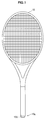
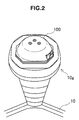
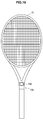
- FIGS. 1 and 2 are explanatory diagrams illustrating a position at which a sensor device is fitted on a hitting tool according to a first embodiment of the present disclosure.
- a sensor device 100 is fitted on a grip end 10g of a racket 10 in the embodiment.
- the grip end 10g has a cylindrical shape and a part of the sensor device 100 fits into the grip end 10g.
- the sensor device 100 fitting into the grip end 10g also has a substantially octagonal cross-sectional shape.
- the racket 10 on which the sensor device 100 is fitted is a hitting tool that is used in tennis.
- An example of the hitting tool according to an embodiment of the present disclosure is not limited to a tennis racket.
- An embodiment of the present disclosure can be applied to hitting tools used in, for example, all sports such as a badminton racket, a table tennis paddle, a golf club, and a baseball bat.
- FIG. 3 is an explanatory diagram illustrating a schematic configuration of the sensor device according to the first embodiment of the present disclosure.
- the sensor device 100 includes a fitting member 102, a base member 104, and an exterior member 110.
- the base member 104 is detachably mounted on the fitting member 102 and the fitting member 102 fits into the grip end 10g of the racket 10 so that the base member 104 is fitted on the racket 10.
- the exterior member 110 covers a sensor, a communication device, and the like disposed on the base member 104 to protect them.
- the fitting member 102 is a member that is independent from the grip end 10g to form a fitting structure for fitting the base member 104 on the grip end 10g.
- the fitting member 102 has an octagonal pillar portion fitting into the grip end 10g, and an opening 102g leading to the inside of the octagonal pillar portion is formed on an upper surface 102u of the fitting member 102 facing the base member 104.
- a cylindrical protrusion 104a corresponding to the opening 102a is formed on a lower surface 104u of the base member 104.
- the protrusion 104a is inserted into the opening 102a so that the base member 104 is mounted on the fitting member 102.
- the protrusion 104a is inserted into the opening 102a. Thereafter, by rotating the base member 104 with respect to the fitting member 102, the base member 104 is fixed to the fitting member 102.
- FIG. 4 is a cutaway perspective view illustrating the sensor device according to the first embodiment of the present disclosure.
- FIG. 5 is a sectional view illustrating the sensor device illustrated in FIG. 4 .
- the cross-sectional surface of FIG. 5 is identical to the cutaway surface of FIG. 4 .
- the configuration of the sensor device 100 according to the embodiment will be described in detail with reference to the drawings.
- the fitting member 102 has a shape corresponding to the shape of the fitting portion of the racket 10.
- the fitting member 102 has an octagonal pillar portion 102c fitting into the grip end 10g of the racket 10.
- the octagonal pillar portion 102c has a shape corresponding to the inner wall surface of the grip end 10g, and thus the fitting member 102 can be brought into close contact with the grip end 10g.
- a latch claw 102h may be provided at a tip end of the octagonal pillar portion 102c.
- the fitting member 102 fits into the grip end 10g to be fixed, and thus a motion of acceleration, angular velocity, vibration or the like occurring in the racket 10 is delivered from the grip end 10g.
- the fitting member 102 supports the base member 104 mounted thereon and delivers a motion of the racket 10 delivered from the grip end 10g via the octagonal pillar portion 102c to the base member 104.
- the base member 104 is detachably mounted on the fitting member 102 to form a base of another member of the sensor device 100.
- a sensor substrate 106 is joined to the base member 104, and a communication substrate 108 and an exterior member 110 are directly or indirectly supported by the base member 104.
- the base member 104 comes into contact with the fitting member 102 by line contact or point contact so that a motion of acceleration, angular velocity, vibration or the like delivered from the grip end 10g is delivered from the fitting member 102.
- a battery case 112 is internally included inside the cylindrical protrusion 104a of the base member 104 penetrating into the octagonal pillar portion 102c of the fitting member 102.
- a battery 114 is accommodated in the battery case 112.
- an accommodation portion for the battery 114 is disposed inside the grip end 10g so that a portion of the sensor device 100 bulging outside the grip end 10g can be further decreased, and the battery 14 is distant from a communication circuit 122 to be described below so that it is possible to reduce an influence on communication of the communication circuit 122.
- the base member 104 may be detachably mounted on the fitting member 102.
- the base member 104 and the fitting member 102 can be detachably mounted, the base member 104 and another member (hereinafter referred to as a body portion along with the base member 104) disposed on the base member 104 can be standardized by matching the shape of the fitting member 102 to each grip end 10g.
- the fitting member 102 with a shape corresponding to the grip end 10g of each racket 10 can be prepared and the common body portion can be used instead.
- the common body portion can be used, economy can be realized from the viewpoint of the user and the same sensor can be used when playing with another racket. Therefore, there is also an advantage from the viewpoint of continuously acquiring sensor data.
- a lock mechanism 116 may be provided in the base member 104 to prevent the base member 104 from coming off of the fitting member 102 and prevent the body portion from falling down during play.
- the configuration of the lock mechanism 116 will be described below.
- FIG. 6 is a diagram illustrating several examples of the grip end 10g.
- the grip end 10g can have an internal octagonal shape.
- the sizes of the internal octagonal portions can differ depending on rackets.
- the grip end 10g has an internal elliptical shape in some cases.
- an embodiment of the present disclosure is not limited to the grip end of the racket and the shape of each portion of a hitting tool differs according to, for example, a maker. Therefore, it is important that the sensor device can be easily fitted on hitting tools with different shapes and not easily come out even when the hitting tool is swung or a ball is hit with the hitting tool.
- the sensor substrate 106 is joined to the base member 104.
- a sensor 118 and a preprocessing circuit 120 amplifying data detected by the sensor 118 or filtering data equal to or less than a threshold value can be disposed on the sensor substrate 106.
- the sensor 118 can include an acceleration sensor, a gyro sensor, and a geomagnetic sensor.
- the acceleration sensor may include a uniaxial shock sensor detecting an impact occurring in the racket 10 and a triaxial motion sensor detecting acceleration of the racket 10 at a higher resolution than the shock sensor.
- a motion such as vibration, acceleration, or angular velocity occurring in the racket 10 is delivered from the grip end 10g via the fitting member 102 and the base member 104.
- the sensor 118 detects the motion such as vibration, acceleration, or angular velocity delivered up to the sensor substrate 106 in this way as a motion of the racket 10. Accordingly, the motion such as vibration, acceleration, or angular velocity occurring in the racket 10 is preferably delivered to the sensor 118 while the characteristics of the motion are maintained as much as possible.
- the members along a delivery route of the motion of the racket 10, that is, the fitting member 102, the base member 104, and the sensor substrate 106, preferably have materials and shapes for preserving frequency characteristics of vibration which is one of the motions occurring in the racket 10.
- shape for example, cross-sectional areas may be ensured to some extent in each member and an embodiment of the present disclosure is not limited to the shapes illustrated in the examples.
- materials for example, in the case of the tennis racket 10, a swing feature is shown in vibration of a range equal to or less than about 2 kHz. Therefore, for example, a polycarbonate or a hard metal is preferably used for each member so that the frequency characteristics of this range can be preserved.
- a silicon-based material is not preferable since the frequency characteristics are not preserved.
- a switching feature is shown in vibration of a range equal to or less than about 10 kHz. Therefore, a material of each member is preferably selected so that the frequency characteristics of this range can be preserved.
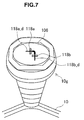
- FIG. 7 is a diagram illustrating a first example of sensor disposition in the sensor device according to the first embodiment of the present disclosure.
- FIG. 8 is a diagram illustrating a second example of the sensor device in the sensor device according to the first embodiment of the present disclosure.
- two sensors 118a and 118b are disposed on the sensor substrate 106 so that detection directions 118a_d and 118b_d are orthogonal to each other.
- the shape of the sensor substrate 106 is schematically illustrated to show a relation between the racket 10 and each detection direction and is not necessarily identical to the shape of the sensor substrate illustrated in other drawings.
- the detection direction 118a_d is a direction parallel to a hitting plane of the racket 10 and the detection direction 118b_d is perpendicular to the hitting plane of the racket 10.
- the detection direction 118a_d is a direction parallel to a hitting plane of the racket 10 and the detection direction 118b_d is perpendicular to the hitting plane of the racket 10.
- the same information can be extracted by separating detected vibration into two detection directions in a direction parallel to the hitting plane and a direction perpendicular to the hitting plane.
- the two detection directions are preferably orthogonal to each other in consideration of precision of the detection results after the separation.
- the precision of the detection result is the highest when the detection directions are identical to the direction parallel to the hitting plane and the direction perpendicular to the hitting plane.
- a single sensor 118c is disposed on the sensor substrate 106 so that a detection direction 118c_d is oblique to the hitting plane of the racket 10.
- the shape of the sensor substrate 106 is schematically illustrated to show a relation between the racket 10 and the detection direction and is not necessarily identical to the shape of an actual sensor substrate.
- the detection direction may be inclined at about 45 degrees with respect to the hitting plane.
- the sensor 118c may be disposed at an asymmetric position deviated from the central axis of the hitting plane of the racket 10 and a distribution of vibration on the hitting plane may be considered to be symmetric to the central axis.
- the precision of the detection result is higher when a plurality of sensors are disposed as in the foregoing first example.
- the communication substrate 108 is indirectly connected to the base member 104.
- a communication circuit 122, an antenna 124, and the like transmitting the detection result of a motion of the racket 10 detected by the sensor 118 and processed by the preprocessing circuit 120 to an external device, more specifically, an analysis device, can be disposed on the communication substrate 108.
- wireless communication is used to transmit the detection result.
- a communication scheme is not particularly limited. For example, when the analysis device of a transmission destination is near the sensor device 100, short-range wireless communication such as Bluetooth (registered trademark) or a wireless local area network (LAN) can be used.
- the communication circuit 122 and the antenna 124 are disposed on an opposite side to the battery case 112 with the base member 104 and the sensor substrate 106 interposed therebetween, it is possible to minimize an influence on communication due to, for example, blocking of radio waves by a metal included in the battery case 112 or the battery 114.
- a control circuit controlling an operation of the communication circuit 122 may be provided on the communication substrate 108.
- the control circuit controls execution or pause of the transmission of the detection result, for example, according to a user manipulation acquired via a button 126 or the like that is provided, as necessary.
- a control circuit controlling an operation of the preprocessing circuit 120 (capable of controlling an operation of the sensor 118 when the sensor 118 includes an active type sensor) may be provided on the sensor substrate 106.
- a control circuit controlling both of the communication circuit 122 and the preprocessing circuit 120 may be provided on the sensor substrate 106 or the communication substrate 108.
- a motion such as vibration, acceleration, or angular velocity occurring in the racket 10 may not be delivered to the communication substrate 108. That is, vibration, acceleration, angular velocity, or the like may be attenuated or denatured between the base member 104 and the communication substrate 108. Therefore, for example, the communication substrate 108 may be indirectly connected to the base member 104 or may be connected to the side of the exterior member 110 via a buffer member such as an elastomer in order to protect the communication circuit 122 or the like against vibration. Alternatively, when it is not particularly necessary to protect the communication circuit 122 or the like, the communication substrate 108 may be joined to the base member 104 as in the sensor substrate 106 so that vibration occurring in the racket 10 is delivered.
- the exterior member 110 is provided on the base member 104 to cover the sensor substrate 106 and the communication substrate 108.
- the exterior member 110 can have a structure that protects the sensor 118 on the sensor substrate 106 and the communication circuit 122 on the communication substrate 108 from an external impact.
- An external impact occurs, for example, when the sensor device 100 fitted on the grip end 10g of the racket 10 collides with the body of a user, another mechanism such as a ball, or the ground.
- the exterior member 110 has a two-layered structure of the external soft portion 110a and an internal hard portion 110b, and the soft portion 110a may absorb an external impact to prevent the external impact from being delivered to the sensor 118, the communication circuit 122, or the like.
- the soft portion 110a can be formed of a material such as an elastomer and the hard portion 110b can be formed of a material such as acrylonitrile butadiene styrene (ABS) or a polycarbonate.
- ABS acrylonitrile butadiene styrene
- a space may be formed between the sensor 118 and the communication circuit 122 to protect these members against an external impact.
- a space is formed between the communication circuit 122 disposed on the communication substrate 108 and the exterior member 110 and a space is further formed between the sensor 118 disposed on the substrate 106 and the communication substrate 108 on the sensor 118, so that the foregoing structure is realized.
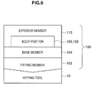
- FIG. 9 is a diagram schematically illustrating the configuration of the sensor device according to the first embodiment of the present disclosure described above.
- the sensor device 100 is classified into the fitting member 102, the base member 104, the body portions 106 and 108, and the exterior member 110.
- the fitting member 102 By detachably mounting the fitting member 102 on the base member 104, it is possible to cause the base member 104, the body portions 106 and 108, and the exterior member 110 to be standardized to correspond to various shapes which the fitting portion (the grip end 10g in the foregoing example) of the racket 10 can have by changing the fitting member 102.
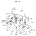
- FIG. 10 is an explanatory diagram illustrating a lock mechanism in a first example of a junction structure between a fitting member and a base member of the sensor device according to the first embodiment of the present disclosure.
- the lock mechanism 116 disposed on a surface on the base member 104 faces the fitting member 102 and includes a pin member 116a, a knob 116b, and a spring 116c.
- the base member 104 is fixed to the fitting member 102 by rotating the base member 104 with respect to the fitting member 102.
- the pin member 116a that is pressed downward by the spring 116c to protrude from the base member 104 and the pin member 116a to penetrate into a hole portion 102k formed at a position corresponding to the fitting member 102 in the lock mechanism 116 rotation of the base member 104 in the fixed state to the fitting member 102 is prevented.
- the base member 104 is prevented from coming off of the fitting member 102 and the body portion is prevented from falling.
- the user When the user intentionally takes the base member 104 off of the fitting member 102, the user slides the knob 116b in a direction D2. Then, the pin member 116a ascends against the spring 116c due to an engagement structure of the knob 116b and the pin member 116a and slips off of the hole portion 102k of the fitting member 102, as illustrated in the drawing. Accordingly, the user can detach the base member 104 from the fitting member 102 by rotating the base member 104 with respect to the fitting member 102.
- the rib 104r When the base member 104 is mounted on the fitting member 102, the rib 104r is thrust into the groove 102g by rotating the base member 104 with respect to the fitting member 102, as described above.
- the groove 102g is formed in a portion higher than the other portions of the upper surface of the fitting member 102. Therefore, the base member 104 is lifted by a height h more than the other portions to be elastically deformed in the portion in which the rib 104r is thrust into the groove 102g.
- the rib 104r is pressed in the groove 102g by a restoring force F1 from the elastic deformation.
- a connection structure by the rib 104r and the groove 102g is formed in a plurality of spots (for example, three or more spots) of the junction portion, as illustrated in FIG. 12 .
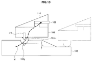
- FIG. 13 is an explanatory diagram illustrating a second example of the line contact structure in the first example of the junction structure of the fitting member and the base member of the sensor device according to the first embodiment of the present disclosure.
- FIG. 13 is a longitudinal sectional view illustrating the junction portion. Since FIG. 13 is a schematic diagram, the shape of each member is not necessarily identical to the shapes illustrated in the other diagrams.
- a flat spring 104s protruding toward the facing fitting member 102 is disposed on the lower surface of the base member 104.
- a groove 102g corresponding to the flat spring 104s is formed on the upper surface of the fitting member 102.
- a connection structure by the flat spring 104s and the groove 102g is formed in a plurality of spots (for example, three or more spots) of the junction portion, as in the first example illustrated in FIG. 12 .
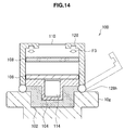
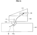
- FIGS. 14 and 15 are explanatory diagrams illustrating a second example of the junction structure between the fitting member and the base member of the sensor device according to the first embodiment of the present disclosure.
- FIG. 14 is a longitudinal sectional view illustrating the entire sensor device.
- FIG. 15 is a schematic longitudinal sectional view illustrating the junction portion. Since both of the drawings are schematic diagrams, the shape of each member is not necessarily identical to the shapes illustrated in the other diagrams.
- the rib 104r is formed on the lower surface of the base member 104 and the groove 102g is formed on the upper surface of the fitting member 102, as in the foregoing first example.
- the height of the portion in which the groove 102g is formed is the same as the other portions of the upper surface of the fitting member 102.
- the rib 104r is pressed downward in the groove 102g by a force F3 by which the arm 128 presses the body portion downward, it is not necessary to realize a configuration such as the stepped difference of the fitting member 102 for obtaining a restoring force of the base member 104 as in the foregoing first example.
- Screws are set on the inner circumferential surface of the screw-attached ring 130 and the outer circumferential surface of the fitting member 102, and the screws are engaged so that a force by which the screw-attached ring 130 presses the base member 104 against the fitting member 102 can be obtained.
- the screw-attached ring 130 includes an engagement portion 130h engaging with the upper surface of the base member 104, and the base member 104 is pressed against the fitting member 102 from the upper side by the engagement portion 130h.
- a lock such as a ratchet mechanism is preferably provided in the screw-attached ring 130.
- FIG. 17 is an explanatory diagram illustrating a modification of the third example of the junction structure between the fitting member and the base member of the sensor device according to the first embodiment of the present disclosure.
- an O ring 132 is disposed in a groove 110g provided in a region in which the exterior member 110 comes into contact with the base member 104.
- circuit components provided in the sensor substrate 106 or the communication substrate 108 inside the exterior member 110 can be protected against from external water or moisture.
- the similar waterproof structure is not limited to the third example, but can also be applied to the foregoing first and second examples.
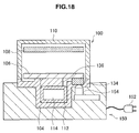
- FIG. 18 is an explanatory diagram illustrating a connection example of a charger of the sensor device according to the first embodiment of the present disclosure.
- FIG. 18 is a schematic longitudinal sectional view illustrating a state in which a part of the sensor device 100 is detached and connected to a charger 150. Since FIG. 18 is a schematic diagram, the shape of each member is not necessarily identical to the shapes illustrated in the other diagrams. Referring to FIG. 18 , a part of the sensor device 100 including the base member 104 detached from the fitting member 102 is detachably mounted on the charger 150 that has a shape corresponding to a mounting portion of the base member 104 on the fitting member 102.
- the part of the sensor device 100 including the base member 104 is fixed to the charger 150 by inserting the protrusion 104a into the charger 150 and then rotating the base member 104 with respect to the charger 150, as in the case of the mounting on the fitting member 102, as described with reference to FIG. 3 .
- the part of the sensor device 100 is fixed to the charger 150 and the battery 114 is connected to an external power source via a connection wiring 136, the connection terminal 134, the charging terminal 154, and a power plug 152, so that charging starts.
- the user can connect the sensor device 100 to the charger 150 through the same operation as when the base member 104 is mounted on the fitting member 102.
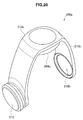
- FIG. 20 is a schematic perspective view illustrating a first example of the sensor device according to the second embodiment of the present disclosure.
- a sensor device 200a includes a lower case 204a, an upper case 210a, and a belt 210b connected to the upper case 210a.
- a battery case 212 is disposed at one end of the belt 210b and a protrusion is formed on the outside of the belt 210b.
- a belt hole 210h is formed at the other end of the belt 210b.
- the battery case 212 which is a protrusion is inserted into the belt hole 210h, the belt 210b is wound around the grip 10h to be fixed.
- a fitting member (not illustrated) is disposed on the lower surface of the lower case 204a. Since the fitting member is the same as that in the second example of the embodiment to be described below, the description of the second example will be referred to.
- the fitting member 202a delivers a motion of the racket 10 such as vibration, acceleration, or angular velocity delivered from the grip 10h to the lower case 204a. Therefore, for example, rigid connection can be realized without providing a buffer member such as an elastomer between the fitting member 202a and the lower case 204a.
- Both of the fitting member 202a and the lower case 204a preferably have materials and shapes for preserving frequency characteristics of vibration which is one of the motions occurring in the racket 10.
- a motion of the racket 10 delivered to the lower case 204a is delivered to a sensor substrate 206 joined to the lower case 204a and is detected by a sensor 218 disposed on the sensor substrate 206.
- a preprocessing circuit (not illustrated), a communication circuit 222, an antenna (not illustrated), and a control circuit (not illustrated) are integrated along with the sensor 218 on the sensor substrate 206.
- the upper case 210a is provided on the lower case 204a to protect the sensor 218 and the communication circuit 222 disposed on the sensor substrate 206 against an external impact.
- the sensor device 200b includes a belt 204b connected to the lower case 204a.
- the belt 204b is connected to both sides of the lower case 204a to be wound around the grip 10h and is connected to a facing case 204c on the opposite side with the grip 10h interposed therebetween from the lower case 204a.
- the battery case 212 is provided in the facing case 204c and the battery 214 can be stored in the battery case 212.
- the fitting member 202b having a shape corresponding to the fitting surface of the grip 10h as in the fitting member 202a is also provided in the facing case 204c.
- the fitting member 202b may attenuate or denature vibration, acceleration, angular velocity, or the like delivered from the grip 10h.
- the fitting member 202b may be connected to the lower case 204c via a buffer member such as an elastomer or the fitting member 202b may be configured as an elastomer.
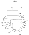
- FIG. 24 is a side view illustrating the sensor device according to the third embodiment of the present disclosure.
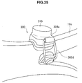
- FIG. 25 is a diagram illustrating a state in which the sensor device illustrated in FIG. 24 is fitted.
- the sensor device 300 includes a lower case 304, an upper case 310, and a clasp 302 connected to the lower case.
- the clasp 302 includes a base 302a, an arm 302b, a hinge 302c connecting the base 302a to the arm 302b, and a clip 302d.
- a sensor substrate, a sensor, a communication circuit, and the like are disposed on the lower case 304 to be protected against an external impact by the upper case 310.
- the sensor device 300 is fixed to the racket 10 in such a manner that the clasp 302 holds the shaft 10s of the racket 10 when the clip 302d presses the arm 302b to the inside using an elastic force or the like of a spring.
- a motion such as vibration, acceleration, or angular velocity occurring in the racket 10 is delivered to the clasp 302 and the lower case 304.
- the delivered motion is delivered to a sensor substrate (not illustrated) via the lower case 304 and is detected by the sensor.
- a sensor device according to the embodiment is fitted on a shaft of a racket, as in the sensor device 300 according to the third embodiment, but is different from the sensor device 300 in a fitting method. Since other details are the same as those of the sensor device 300, the repeated description will be omitted below.
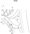
- FIG. 26 is a perspective view illustrating a state in which the sensor device is fitted according to the fourth embodiment of the present disclosure.
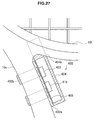
- FIG. 27 is a sectional view taken along the line A-A of FIG. 26 .
- a sensor device 400 includes a fitting member 402a and a case 404.
- the fitting member 402a is fixed to the shaft 10s by a band 402b.
- the band 402b is wound around the shaft 10s using, for example, a plane fastener.
- the fitting member 402a since the fitting member 402a has a shape corresponding to the surface of the shaft 10s and comes into contact with the shaft 10s to be fixed, a motion such as vibration, acceleration, or angular velocity occurring in the racket 10 is delivered to the fitting member 402a.
- rigid connection can be realized without providing a buffer member such as an elastomer between the fitting member 402a and the case 404 so that a motion of the racket 10 delivered to the fitting member 402a is delivered to the case 404.
- a pair of claws 404b are provided in the case 404.
- the claws 404b are provided to surround a frame 10f of the racket 10 when the sensor device 400 is fitted on the shaft 10s. That is, the sensor device 400 is fixed by winding the band 402b around the shaft 10s and is also fixed by the claws 404b surrounding the frame 10f.
- the position of the sensor device 400 is not changed even when a centrifugal force (in a direction directed from the shaft 10s to the side of the frame 10f) is received when the racket 10 is swung and the sensor device 400 is also prevented from being rotated with rotation of the shaft 10s.
- a sensor device according to the embodiment is fitted on a shaft of a racket, as in the sensor device 300 according to the third embodiment, but is different from the sensor device 300 in a fitting method. Since other details are the same as those of the sensor device 300, the repeated description will be omitted below.
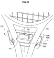
- FIG. 28 is a perspective view illustrating a state in which a sensor device is fitted according to a fifth embodiment of the present disclosure.
- FIG. 29 is a sectional view taken along the line B-B of FIG. 28 .
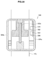
- FIG. 30 is a sectional view taken along the line C-C of FIG. 28 .
- a sensor device 500 includes a case 504 and a tightening member 502.
- the perspective view of FIG. 28 illustrates a state in which a part of the case 504 is detached.
- the case 504 can be separated into cases 504a and 504b in front and rear directions of the racket 10. As illustrated particularly in FIG. 29 , the cases 504a and 504b are disposed to pass through penetrated portions 504c corresponding to both of two shafts 10s and are combined to form the case 504.
- a motion such as vibration, acceleration, or angular velocity occurring in the racket 10 is delivered to the case 504.
- the motion of the racket 10 delivered to the case 504 is delivered to the sensor substrate 506 joined to the case 504 and is detected by the sensor 518 disposed on the sensor substrate 506.
- a preprocessing circuit (not illustrated), a communication circuit 522, an antenna (not illustrated), and a control circuit (not illustrated) are integrated along with the sensor 518 on the sensor substrate 506.
- the case 504 coves the sensor substrate 506 and also functions as an exterior member that protects the sensor 518 and the communication circuit 522 disposed on the sensor substrate 506 against an external impact.
- FIG. 32 is an explanatory diagram illustrating a schematic configuration of the sensor device according to the sixth embodiment of the present disclosure.
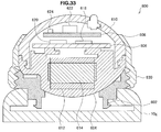
- FIG. 33 is a sectional view illustrating the sensor device illustrated in FIG. 32 .
- the sensor device 600 includes a fitting member 602, a base member 604, a sensor substrate 606, a communication substrate 608, an exterior member 610, a battery case 612, a battery 614, a sensor 618, a preprocessing circuit 620, a communication circuit 622, an antenna 624, and a screw-attached ring 630.
- the functions of the members can be the same as those of the fitting member 102, the base member 104, the sensor substrate 106, the communication substrate 108, the exterior member 110, the battery case 112, the battery 114, the sensor 118, the preprocessing circuit 120, the communication circuit 122, the antenna 124, and the screw-attached ring 130 described in the foregoing first embodiment.
- a body portion including the base member 604 and the exterior member 610 can be detached from the fitting member 602 and can also be detached from the screw-attached ring 630. Therefore, for example, the body portion can be fitted on a charger with a shape corresponding to the base member 604 to be charged, as in the above-described charger 150, or can be mounted on the fitting member 602 incorporated into another racket or can be mounted on the fitting member 602 fitted on a hitting tool other than a racket.
- the sensor device 600 is different from the sensor device (the screw-attached ring 130 is engaged with the upper surface of the base member 104, and thus is not necessarily a detachably mounted member) described with reference to FIGS. 16 and 17 in that the screw-attached ring 630 is detachably mounted on the base member 604.
- FIG. 34 is an explanatory diagram illustrating a schematic configuration of a sensor device according to the seventh embodiment of the present disclosure.
- FIG. 35 is a sectional view illustrating the sensor device illustrated in FIG. 34 .
- the fitting member 702 includes a claw 702e that engages with a groove inside the grip end 10g and functions as a latch.
- the fitting member 702 strongly locks in the grip end 10g through an operation of the claw 702e and the body portion on the base member 704 is mounted on the fitting member 702 so that, for example, impact resistance of the sensor device 700 in a surface fitted state can be improved.
- a user rotates the arm portion 702m of the fitting member 702 toward the center side of the grip with his or her finger or the like (performs an operation of raising the arm portion 702m to the inside) and the arm portion 702m is urged toward the center side of the grip by an urging unit such as a separately provided spring, so that the engagement of the claw 702e and the groove of the grip end 10g can be released and the fitting member 702 can be easily detached from the grip end 10g.
- an urging unit such as a separately provided spring
- a protrusion 702f is formed on the center side of the grip on the opposite side of the claw 702e.
- the protrusion 702f comes into contact with a bottom surface 704b of the base member 704 when the claw 702e engages with the groove of the grip end 10g. Accordingly, when the claw 702e does not engage with the groove of the grip end 10g and a protrusion 704a of the base member 704 is inserted into an opening 702a, the protrusion 702f comes into contact with the bottom surface 704b during the insertion to be pushed down. Thereafter, the arm portion 702m is rotated toward the outside of the grip about the hinge 702h, so that the claw 702e consequently engages with the groove of the grip end 10g.
- a rib 704r protruding toward the facing fitting member 702 is formed on the bottom surface of the base member 704.
- a groove 702g corresponding to the rib 704r is formed on the upper surface of the fitting member 702.
- the rib 704r and the groove 702g function like the rib 104r and the groove 102g in the above-described first embodiment and provide line contact or point contact between the base member 704 and the fitting member 702, so that rattling can be suppressed and a motion of the racket 10 can be delivered from the fitting member 102 to the base member 104 by stable junction
- FIG. 36 is an explanatory diagram illustrating a schematic configuration of a sensor device and a grip end according to the eighth embodiment of the present disclosure.
- FIG. 37 is a sectional view illustrating a grip end taken along the line D-D of FIG. 36 .
- a relation between the fitting structure 802 and the base member 804 can be the same as, for example, the relation between the fitting member 102 and the base member 104 of the sensor device 100 according to the foregoing first embodiment. More specifically, for example, an opening 802a is formed in an upper surface 802u of the fitting structure 802, and thus a protrusion 804a formed on the lower surface of the base member 804 is inserted into the opening 802a so that the base member 804 is mounted on the fitting structure 802.
- the fitting structure 802 is integrated with the grip end 10g, mounting of the sensor device 800 on the grip end 10g is completed by mounting the base member 804 on the fitting member 802.
- the fitting structure 802 can include, for example, a configuration related to a junction with the base member 804, as in the fitting member 102 described in the first embodiment.
- a groove 802g into which a rib (not illustrated) formed in the lower surface of the base member 804 is thrust may be formed in the upper surface of the fitting structure 802. Since the fitting structure 802 is integrated with the grip end 10g, the fitting structure 802 does not have, for example, a configuration for joining the grip end 10g and the fitting member 102 described in the first embodiment, more specifically, the configuration of the claw 102h.
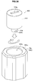
- FIGS. 38 and 39 are explanatory diagrams illustrating a schematic configuration of a sensor device and a grip end according to the ninth embodiment of the present disclosure.
- FIG. 38 illustrates a state before mounting and
- FIG. 39 illustrates a state after mounting.
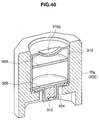
- FIG. 40 is a sectional view illustrating the sensor device and the grip end taken along the line E-E of FIG. 39 .
- FIG. 41 is an explanatory diagram illustrating a junction structure between a fitting structure and a base member of the sensor device according to the ninth embodiment of the present disclosure.
- the sensor device 900 includes a base member 904, a sensor substrate 906, a communication substrate 908, an exterior member 910, and a battery case 912.
- the sensor device 900 has the same configuration as the sensor device 100 described in the foregoing first embodiment except that the fitting structure 902 is integrated with the grip end 10g and the body portion including the base member 904 can be accommodated in the grip end 10g. Therefore, the detailed description other than that of a fitting structure 902 (the grip end 10g) and members (the base member 904 and the exterior member 910) forming an external shape will be omitted.
- An opening 902a is formed in an upper surface 902u of the fitting structure 902 and the sensor device 900 is mounted on the grip end 10g by accommodating the body portions of the sensor device 900 including the base member 904 in the opening 902a.
- a claw 904h formed in the base member 904 engages with a claw 902h formed in the fitting structure 902, so that the base member 904 is fixed to the fitting structure 902.
- a groove 910g may be formed in the exterior member 910.
- a jig including a case in which a coin or the like is used instead of a jig
- a rib 904r may be formed on the lower surface of the base member 904 and a groove 902g may be formed inside the fitting structure 902 and on the bottom surface of the opening 902a, so that the fitting structure 902 and the base member 904 can be strongly joined by point contact or line contact.
- the fitting structure 902 is not separately manufactured, it is possible to reduce cost occurring due to an increase in the number of members. Further, since there is no junction structure between the fitting structure 902 and the grip end 10g, the rigidity of the fitting portion of the sensor device 900 can be improved. Further, since the number of junction portions is decreased from two to one, it is also possible to reduce noise mixed in the vibration data detected in the sensor device 900.
- FIG. 42 is a sectional view illustrating a schematic configuration of a sensor device and a grip end according to the tenth embodiment of the present disclosure.
- the claws 1004h are opened and closed through an operation of the spring 1004s provided in the base member 1004.
- a state in which the knob 1010k is pushed is a locked state.
- the claws 1004h are opened to engage with claws 1002h formed in the fitting structure 1002, so that the body portion of the sensor device 1000 is fixed to the fitting structure 1002.
- the claws 1004h are closed and the engagement with the claws 1002h is released, so that the locked state becomes an unlocked state.
- the grooves 1010g accommodate protrusion portions of the knob 1010k at positions corresponding to the locked state and the unlocked state to maintain the position of the knob 1010k.
Landscapes
- Health & Medical Sciences (AREA)
- General Health & Medical Sciences (AREA)
- Physical Education & Sports Medicine (AREA)
- Physics & Mathematics (AREA)
- Life Sciences & Earth Sciences (AREA)
- Engineering & Computer Science (AREA)
- General Physics & Mathematics (AREA)
- Veterinary Medicine (AREA)
- Radar, Positioning & Navigation (AREA)
- Molecular Biology (AREA)
- Surgery (AREA)
- Animal Behavior & Ethology (AREA)
- Pathology (AREA)
- Medical Informatics (AREA)
- Biophysics (AREA)
- Public Health (AREA)
- Heart & Thoracic Surgery (AREA)
- Biomedical Technology (AREA)
- Remote Sensing (AREA)
- Golf Clubs (AREA)
- Toys (AREA)
- Force Measurement Appropriate To Specific Purposes (AREA)
Abstract
Description
- The present disclosure relates to a sensor device fitted on a hitting tool.
- Many technologies for assist users with improvement in sports using sensing or analysis have been developed already. For example,
Patent Literature 1 describes a technology for extracting feature information of a swing by analyzing a detection result supplied by a sensor device including an angular velocity sensor or an acceleration sensor fitted on a hitting tool such as a golf club used by a user. - Patent Literature 1:
JP 2012-157644A - In the above-described technology, since it is necessary for the sensor to precisely detect a motion of the hitting tool, the way in which the sensor device is fitted on the hitting tool is important. However, it is hard to say that the structure of the sensor device including a portion fitted on the hitting tool has been sufficiently proposed in, for example,
Patent Literature 1 described above. - Accordingly, it is desirable to provide a novel and improved sensor device in which a motion of a hitting tool can be detected more precisely by a sensor.
- According to the present disclosure, there is provided a sensor device including: a base member configured to be mounted on a hitting tool via a fitting structure; a substrate joined to the base member; a sensor disposed on the substrate and configured to detect a motion of the hitting tool delivered via the base member and the substrate; a communication unit configured to transmit a detection result of the motion of the hitting tool to an external device; and an exterior member configured to cover the sensor and the communication unit.
- When the base member is fitted on the hitting tool via a fitting structure, the base member is fitted so that a motion of the hitting tool is delivered to the sensor via the base member, and thus the motion of the hitting tool can be detected more precisely by the sensor.
- According to an embodiment of the present disclosure described above, a motion of a hitting tool can be detected more precisely by a sensor.
-
- [
FIG. 1] FIG. 1 is an explanatory diagram illustrating a position at which a sensor device is fitted on a hitting tool according to a first embodiment of the present disclosure. - [
FIG. 2] FIG. 2 is an explanatory diagram illustrating a position at which a sensor device is fitted on a hitting tool according to the first embodiment of the present disclosure. - [
FIG. 3] FIG. 3 is an explanatory diagram illustrating a schematic configuration of the sensor device according to the first embodiment of the present disclosure. - [
FIG. 4] FIG. 4 is a cutaway perspective view illustrating the sensor device according to the first embodiment of the present disclosure. - [
FIG. 5] FIG. 5 is a sectional view illustrating the sensor device illustrated inFIG. 4 . - [
FIG. 6] FIG. 6 is a diagram illustrating several examples of the shape of a grip end when a cap is removed. - [
FIG. 7] FIG. 7 is a diagram illustrating a first example of sensor disposition in the sensor device according to the first embodiment of the present disclosure. - [
FIG. 8] FIG. 8 is a diagram illustrating a second example of sensor disposition in the sensor device according to the first embodiment of the present disclosure. - [
FIG. 9] FIG. 9 is a diagram schematically illustrating the configuration of the sensor device according to the first embodiment of the present disclosure. - [
FIG. 10] FIG. 10 is an explanatory diagram illustrating a lock mechanism in a first example of a junction structure between a fitting member and a base member of the sensor device according to the first embodiment of the present disclosure. - [
FIG. 11] FIG. 11 is an explanatory diagram illustrating a first example of a line contact structure in the first example of the junction structure of the fitting member and the base member of the sensor device according to the first embodiment of the present disclosure. - [
FIG. 12] FIG. 12 is an explanatory diagram illustrating the first example of a line contact structure in the first example of the junction structure of the fitting member and the base member of the sensor device according to the first embodiment of the present disclosure. - [
FIG. 13] FIG. 13 is an explanatory diagram illustrating a second example of a line contact structure in the first example of the junction structure of the fitting member and the base member of the sensor device according to the first embodiment of the present disclosure. - [
FIG. 14] FIG. 14 is an explanatory diagram illustrating a second example of the junction structure between the fitting member and the base member of the sensor device according to the first embodiment of the present disclosure. - [
FIG. 15] FIG. 15 is an explanatory diagram illustrating the second example of the junction structure between the fitting member and the base member of the sensor device according to the first embodiment of the present disclosure. - [
FIG. 16] FIG. 16 is an explanatory diagram illustrating a third example of the junction structure between the fitting member and the base member of the sensor device according to the first embodiment of the present disclosure. - [
FIG. 17] FIG. 17 is an explanatory diagram illustrating a modification of the third example of the junction structure between the fitting member and the base member of the sensor device according to the first embodiment of the present disclosure. - [
FIG. 18] FIG. 18 is an explanatory diagram illustrating a connection example of a charger of the sensor device according to the first embodiment of the present disclosure. - [
FIG. 19] FIG. 19 is an explanatory diagram illustrating a position at which a sensor device is fitted on a hitting tool according to a second embodiment of the present disclosure. - [
FIG. 20] FIG. 20 is a schematic perspective view illustrating a first example of the sensor device according to the second embodiment of the present disclosure. - [
FIG. 21] FIG. 21 is a schematic longitudinal sectional view illustrating the first example of the sensor device according to the second embodiment of the present disclosure. - [
FIG. 22] FIG. 22 is a longitudinal sectional view illustrating the first example of the sensor device according to the second embodiment of the present disclosure. - [
FIG. 23] FIG. 23 is an explanatory diagram illustrating a position at which a sensor device is fitted on a hitting tool according to a third embodiment of the present disclosure. - [
FIG. 24] FIG. 24 is a side view illustrating the sensor device according to the third embodiment of the present disclosure. - [
FIG. 25] FIG. 25 is a diagram illustrating a state in which the sensor device illustrated inFIG. 24 is fitted. - [
FIG. 26] FIG. 26 is a perspective view illustrating a state in which a sensor device is fitted according to a fourth embodiment of the present disclosure. - [
FIG. 27] FIG. 27 is a sectional view taken along the line A-A ofFIG. 26 . - [
FIG. 28] FIG. 28 is a perspective view illustrating a state in which a sensor device is fitted according to a fifth embodiment of the present disclosure. - [
FIG. 29] FIG. 29 is a sectional view taken along the line B-B ofFIG. 28 . - [
FIG. 30] FIG. 30 is a sectional view taken along the line C-C ofFIG. 28 . - [
FIG. 31] FIG. 31 is an explanatory diagram illustrating a position at which a sensor device is fitted on a hitting tool according to a sixth embodiment of the present disclosure. - [
FIG. 32] FIG. 32 is an explanatory diagram illustrating a schematic configuration of the sensor device according to the sixth embodiment of the present disclosure. - [
FIG. 33] FIG. 33 is a sectional view illustrating the sensor device illustrated inFIG. 32 . [FIG. 34] FIG. 34 is an explanatory diagram illustrating a schematic configuration of a sensor device according to a seventh embodiment of the present disclosure. - [
FIG. 35] FIG. 35 is a sectional view illustrating the sensor device illustrated inFIG. 34 . - [
FIG. 36] FIG. 36 is an explanatory diagram illustrating a schematic configuration of a sensor device and a grip end according to an eighth embodiment of the present disclosure. - [
FIG. 37] FIG. 37 is a sectional view illustrating the grip end taken along the line D-D ofFIG. 36 . - [
FIG. 38] FIG. 38 is an explanatory diagram illustrating a schematic configuration of a sensor device and a grip end according to a ninth embodiment of the present disclosure. - [
FIG. 39] FIG. 39 is an explanatory diagram illustrating a schematic configuration of a sensor device and a grip end according to the ninth embodiment of the present disclosure. - [
FIG. 40] FIG. 40 is a sectional view illustrating the sensor device and the grip end taken along the line E-E ofFIG. 39 . - [
FIG. 41] FIG. 41 is an explanatory diagram illustrating a junction structure between a fitting structure and a base member of the sensor device according to the ninth embodiment of the present disclosure. - [
FIG. 42] FIG. 42 is a sectional view illustrating a schematic configuration of a sensor device and a grip end according to a tenth embodiment of the present disclosure. - Hereinafter, preferred embodiments of the present disclosure will be described in detail with reference to the appended drawings. Note that, in this specification and the drawings, elements that have substantially the same function and structure are denoted with the same reference signs, and repeated explanation is omitted.
- The description will be made in the following order.
- 1. First embodiment
- 1-1. Overall configuration
- 1-2. First example of junction structure
- 1-3. Second example of junction structure
- 1-4. Third example of junction structure
- 1-5. Example of charger connection
- 2. Second embodiment
- 3. Third embodiment
- 4. Fourth embodiment
- 5. Fifth embodiment
- 6. Sixth embodiment
- 7. Seventh embodiment
- 8. Eighth embodiment
- 9. Ninth embodiment
- 10. Tenth embodiment
- 11. Supplement
- Since a user has a plurality of hitting tools in sports plays in many cases, a sensor device preferably has an easily detachably mounted structure. Such easy detaching and mounting is also necessary at the time of charging or software update. On the other hand, when a ball is hit with a hitting tool or the hitting tool falls, impact acceleration of hundreds of G to thousands of G is applied to the sensor device depending on a case. Even in this case, it is necessary to closely stick the sensor device to a hitting tool so that the sensor device does not come off of the hitting tool or fitting of the sensor device does not become loose. Simultaneously, it is necessary to provide a mechanism delivering a minute vibration component (equal to or less than 1 G) occurring in a hitting tool to a sensor circuit without attenuation while protecting a sensor circuit against destruction or looseness caused due to the above impact. It is difficult to realize a mechanism capable of sensing even minute vibration equal to or less than only 1 G simultaneously while protecting a sensor circuit from an impact of thousands of G and capable of being easily detachably mounted.
- Accordingly, in several embodiments to be described below, fitting mechanisms that are fitted on hitting tools with any shape and that acquire vibration of a hitting tool with high precision and simultaneously protect contents against an external impact will be proposed.
-
FIGS. 1 and2 are explanatory diagrams illustrating a position at which a sensor device is fitted on a hitting tool according to a first embodiment of the present disclosure. Referring toFIG. 1 , asensor device 100 is fitted on agrip end 10g of aracket 10 in the embodiment. Thegrip end 10g has a cylindrical shape and a part of thesensor device 100 fits into thegrip end 10g. As illustrated inFIG. 2 , since thegrip end 10g has a substantially octagonal cross-sectional shape, thesensor device 100 fitting into thegrip end 10g also has a substantially octagonal cross-sectional shape. - In the embodiment, the
racket 10 on which thesensor device 100 is fitted is a hitting tool that is used in tennis. An example of the hitting tool according to an embodiment of the present disclosure is not limited to a tennis racket. An embodiment of the present disclosure can be applied to hitting tools used in, for example, all sports such as a badminton racket, a table tennis paddle, a golf club, and a baseball bat. -
FIG. 3 is an explanatory diagram illustrating a schematic configuration of the sensor device according to the first embodiment of the present disclosure. Referring toFIG. 3 , thesensor device 100 includes afitting member 102, abase member 104, and anexterior member 110. In the example illustrated in the drawing, thebase member 104 is detachably mounted on thefitting member 102 and thefitting member 102 fits into thegrip end 10g of theracket 10 so that thebase member 104 is fitted on theracket 10. Theexterior member 110 covers a sensor, a communication device, and the like disposed on thebase member 104 to protect them. Thefitting member 102 is a member that is independent from thegrip end 10g to form a fitting structure for fitting thebase member 104 on thegrip end 10g. - More specifically, the
fitting member 102 has an octagonal pillar portion fitting into thegrip end 10g, and anopening 102g leading to the inside of the octagonal pillar portion is formed on anupper surface 102u of thefitting member 102 facing thebase member 104. Acylindrical protrusion 104a corresponding to theopening 102a is formed on alower surface 104u of thebase member 104. Theprotrusion 104a is inserted into theopening 102a so that thebase member 104 is mounted on thefitting member 102. In the embodiment, when a partial overhang in a circumferential direction provided in theprotrusion 104a is adjusted with a notch of theopening 102a, theprotrusion 104a is inserted into theopening 102a. Thereafter, by rotating thebase member 104 with respect to thefitting member 102, thebase member 104 is fixed to thefitting member 102. -
FIG. 4 is a cutaway perspective view illustrating the sensor device according to the first embodiment of the present disclosure.FIG. 5 is a sectional view illustrating the sensor device illustrated inFIG. 4 . The cross-sectional surface ofFIG. 5 is identical to the cutaway surface ofFIG. 4 . Hereinafter, the configuration of thesensor device 100 according to the embodiment will be described in detail with reference to the drawings. - The
fitting member 102 has a shape corresponding to the shape of the fitting portion of theracket 10. In the embodiment, as such as shape, thefitting member 102 has anoctagonal pillar portion 102c fitting into thegrip end 10g of theracket 10. In the example illustrated in the drawing, theoctagonal pillar portion 102c has a shape corresponding to the inner wall surface of thegrip end 10g, and thus thefitting member 102 can be brought into close contact with thegrip end 10g. Alatch claw 102h may be provided at a tip end of theoctagonal pillar portion 102c. - In such a shape, the
fitting member 102 fits into thegrip end 10g to be fixed, and thus a motion of acceleration, angular velocity, vibration or the like occurring in theracket 10 is delivered from thegrip end 10g. Thefitting member 102 supports thebase member 104 mounted thereon and delivers a motion of theracket 10 delivered from thegrip end 10g via theoctagonal pillar portion 102c to thebase member 104. - The
base member 104 is detachably mounted on thefitting member 102 to form a base of another member of thesensor device 100. Asensor substrate 106 is joined to thebase member 104, and acommunication substrate 108 and anexterior member 110 are directly or indirectly supported by thebase member 104. As will be described below, thebase member 104 comes into contact with thefitting member 102 by line contact or point contact so that a motion of acceleration, angular velocity, vibration or the like delivered from thegrip end 10g is delivered from thefitting member 102. - In the embodiment, a
battery case 112 is internally included inside thecylindrical protrusion 104a of thebase member 104 penetrating into theoctagonal pillar portion 102c of thefitting member 102. Abattery 114 is accommodated in thebattery case 112. Thus, an accommodation portion for thebattery 114 is disposed inside thegrip end 10g so that a portion of thesensor device 100 bulging outside thegrip end 10g can be further decreased, and the battery 14 is distant from acommunication circuit 122 to be described below so that it is possible to reduce an influence on communication of thecommunication circuit 122. - Here, the
base member 104 may be detachably mounted on thefitting member 102. For example, as illustrated inFIG. 6 , there are various variations of the shape of thegrip end 10g of theracket 10. However, since thebase member 104 and thefitting member 102 can be detachably mounted, thebase member 104 and another member (hereinafter referred to as a body portion along with the base member 104) disposed on thebase member 104 can be standardized by matching the shape of thefitting member 102 to eachgrip end 10g. - In such a configuration, for example, since many members can be standardized in the manufacturing of the
sensor device 100, productivity can be improved. When the user owns a plurality ofrackets 10, thefitting member 102 with a shape corresponding to thegrip end 10g of eachracket 10 can be prepared and the common body portion can be used instead. When the common body portion can be used, economy can be realized from the viewpoint of the user and the same sensor can be used when playing with another racket. Therefore, there is also an advantage from the viewpoint of continuously acquiring sensor data. - When the
base member 104 is detachably mounted on thefitting member 102, for example, alock mechanism 116 may be provided in thebase member 104 to prevent thebase member 104 from coming off of thefitting member 102 and prevent the body portion from falling down during play. The configuration of thelock mechanism 116 will be described below. -
FIG. 6 is a diagram illustrating several examples of thegrip end 10g. For example, as illustrated inFIGS. 6A and 6B , thegrip end 10g can have an internal octagonal shape. However, as apparent with reference toFIGS. 6A and 6B , the sizes of the internal octagonal portions can differ depending on rackets. For example, as illustrated inFIG. 6C , thegrip end 10g has an internal elliptical shape in some cases. Thus, an embodiment of the present disclosure is not limited to the grip end of the racket and the shape of each portion of a hitting tool differs according to, for example, a maker. Therefore, it is important that the sensor device can be easily fitted on hitting tools with different shapes and not easily come out even when the hitting tool is swung or a ball is hit with the hitting tool. - Referring back to
FIGS. 4 and5 , thesensor substrate 106 is joined to thebase member 104. For example, asensor 118 and apreprocessing circuit 120 amplifying data detected by thesensor 118 or filtering data equal to or less than a threshold value can be disposed on thesensor substrate 106. Examples of thesensor 118 can include an acceleration sensor, a gyro sensor, and a geomagnetic sensor. Examples of the acceleration sensor may include a uniaxial shock sensor detecting an impact occurring in theracket 10 and a triaxial motion sensor detecting acceleration of theracket 10 at a higher resolution than the shock sensor. - Here, since the
sensor substrate 106 is joined to thebase member 104, a motion such as vibration, acceleration, or angular velocity occurring in theracket 10 is delivered from thegrip end 10g via thefitting member 102 and thebase member 104. Thesensor 118 detects the motion such as vibration, acceleration, or angular velocity delivered up to thesensor substrate 106 in this way as a motion of theracket 10. Accordingly, the motion such as vibration, acceleration, or angular velocity occurring in theracket 10 is preferably delivered to thesensor 118 while the characteristics of the motion are maintained as much as possible. - Accordingly, in the embodiment, by realizing rigid connection between the
grip end 10g and thefitting member 102, between thefitting member 102 and thebase member 104, and between thebase member 104 and thesensor substrate 106 without providing a buffer member such as an elastomer, a motion of theracket 10 is delivered to thesensor 118 as precisely as possible. - The members along a delivery route of the motion of the
racket 10, that is, thefitting member 102, thebase member 104, and thesensor substrate 106, preferably have materials and shapes for preserving frequency characteristics of vibration which is one of the motions occurring in theracket 10. For the shapes, for example, cross-sectional areas may be ensured to some extent in each member and an embodiment of the present disclosure is not limited to the shapes illustrated in the examples. For the materials, for example, in the case of thetennis racket 10, a swing feature is shown in vibration of a range equal to or less than about 2 kHz. Therefore, for example, a polycarbonate or a hard metal is preferably used for each member so that the frequency characteristics of this range can be preserved. - In the case of the
tennis racket 10, a silicon-based material is not preferable since the frequency characteristics are not preserved. As another example, in the case of a golf club, a switching feature is shown in vibration of a range equal to or less than about 10 kHz. Therefore, a material of each member is preferably selected so that the frequency characteristics of this range can be preserved. - Here, examples of detection direction disposition of the
sensor 118 are illustrated inFIGS. 7 and8 .FIG. 7 is a diagram illustrating a first example of sensor disposition in the sensor device according to the first embodiment of the present disclosure.FIG. 8 is a diagram illustrating a second example of the sensor device in the sensor device according to the first embodiment of the present disclosure. - In the first example illustrated in
FIG. 7 , twosensors sensor substrate 106 so that detection directions 118a_d and 118b_d are orthogonal to each other. The shape of thesensor substrate 106 is schematically illustrated to show a relation between theracket 10 and each detection direction and is not necessarily identical to the shape of the sensor substrate illustrated in other drawings. - In the example illustrated in the drawing, the detection direction 118a_d is a direction parallel to a hitting plane of the
racket 10 and the detection direction 118b_d is perpendicular to the hitting plane of theracket 10. In such disposition, for example, it is possible to extract the frequency characteristics of the vibration occurring in theracket 10 from a detection result of thesensor 118b and extract a distribution of the vibration on the hitting plane of theracket 10 from a detection result of thesensor 118a. - Even when the detection directions are not parallel or perpendicular to the hitting plane, the same information can be extracted by separating detected vibration into two detection directions in a direction parallel to the hitting plane and a direction perpendicular to the hitting plane. However, the two detection directions are preferably orthogonal to each other in consideration of precision of the detection results after the separation. As in the example illustrated in the drawing, the precision of the detection result is the highest when the detection directions are identical to the direction parallel to the hitting plane and the direction perpendicular to the hitting plane.
- In the second example illustrated in
FIG. 8 , asingle sensor 118c is disposed on thesensor substrate 106 so that a detection direction 118c_d is oblique to the hitting plane of theracket 10. Even in this drawing, the shape of thesensor substrate 106 is schematically illustrated to show a relation between theracket 10 and the detection direction and is not necessarily identical to the shape of an actual sensor substrate. - In the example illustrated in the drawing, by separating the detection result of the
single sensor 118c into a direction parallel to the hitting plane and a direction perpendicular to the hitting plane, it is possible to extract information regarding the vibration frequency characteristics of the vibration occurring in the direction perpendicular to the hitting plane and information regarding a distribution of the vibration on the hitting plane shown by the vibration in the direction parallel to the hitting plane. - In the foregoing method, two sensors are necessary. However, a method realized by one sensor at lower cost can also be considered, as illustrated in
FIG. 8 . As illustrated in the drawing, the detection direction may be inclined at about 45 degrees with respect to the hitting plane. Alternatively, thesensor 118c may be disposed at an asymmetric position deviated from the central axis of the hitting plane of theracket 10 and a distribution of vibration on the hitting plane may be considered to be symmetric to the central axis. The precision of the detection result is higher when a plurality of sensors are disposed as in the foregoing first example. - Referring back to
FIGS. 4 and5 , thecommunication substrate 108 is indirectly connected to thebase member 104. Acommunication circuit 122, anantenna 124, and the like transmitting the detection result of a motion of theracket 10 detected by thesensor 118 and processed by thepreprocessing circuit 120 to an external device, more specifically, an analysis device, can be disposed on thecommunication substrate 108. For example, wireless communication is used to transmit the detection result. A communication scheme is not particularly limited. For example, when the analysis device of a transmission destination is near thesensor device 100, short-range wireless communication such as Bluetooth (registered trademark) or a wireless local area network (LAN) can be used. As in the example illustrated in the drawing, by disposing thecommunication circuit 122 and theantenna 124 on an opposite side to thebattery case 112 with thebase member 104 and thesensor substrate 106 interposed therebetween, it is possible to minimize an influence on communication due to, for example, blocking of radio waves by a metal included in thebattery case 112 or thebattery 114. - Further, a control circuit (not illustrated) controlling an operation of the
communication circuit 122 may be provided on thecommunication substrate 108. The control circuit controls execution or pause of the transmission of the detection result, for example, according to a user manipulation acquired via abutton 126 or the like that is provided, as necessary. Similarly, a control circuit (not illustrated) controlling an operation of the preprocessing circuit 120 (capable of controlling an operation of thesensor 118 when thesensor 118 includes an active type sensor) may be provided on thesensor substrate 106. Alternatively, a control circuit controlling both of thecommunication circuit 122 and thepreprocessing circuit 120 may be provided on thesensor substrate 106 or thecommunication substrate 108. - Here, unlike the
sensor substrate 106, a motion such as vibration, acceleration, or angular velocity occurring in theracket 10 may not be delivered to thecommunication substrate 108. That is, vibration, acceleration, angular velocity, or the like may be attenuated or denatured between thebase member 104 and thecommunication substrate 108. Therefore, for example, thecommunication substrate 108 may be indirectly connected to thebase member 104 or may be connected to the side of theexterior member 110 via a buffer member such as an elastomer in order to protect thecommunication circuit 122 or the like against vibration. Alternatively, when it is not particularly necessary to protect thecommunication circuit 122 or the like, thecommunication substrate 108 may be joined to thebase member 104 as in thesensor substrate 106 so that vibration occurring in theracket 10 is delivered. - The
exterior member 110 is provided on thebase member 104 to cover thesensor substrate 106 and thecommunication substrate 108. Theexterior member 110 can have a structure that protects thesensor 118 on thesensor substrate 106 and thecommunication circuit 122 on thecommunication substrate 108 from an external impact. An external impact occurs, for example, when thesensor device 100 fitted on thegrip end 10g of theracket 10 collides with the body of a user, another mechanism such as a ball, or the ground. - For example, the
exterior member 110 has a two-layered structure of the externalsoft portion 110a and an internalhard portion 110b, and thesoft portion 110a may absorb an external impact to prevent the external impact from being delivered to thesensor 118, thecommunication circuit 122, or the like. In this case, for example, thesoft portion 110a can be formed of a material such as an elastomer and thehard portion 110b can be formed of a material such as acrylonitrile butadiene styrene (ABS) or a polycarbonate. - In the
exterior member 110, a space may be formed between thesensor 118 and thecommunication circuit 122 to protect these members against an external impact. In the example illustrated in the drawing, a space is formed between thecommunication circuit 122 disposed on thecommunication substrate 108 and theexterior member 110 and a space is further formed between thesensor 118 disposed on thesubstrate 106 and thecommunication substrate 108 on thesensor 118, so that the foregoing structure is realized. -
FIG. 9 is a diagram schematically illustrating the configuration of the sensor device according to the first embodiment of the present disclosure described above. InFIG. 9 , thesensor device 100 is classified into thefitting member 102, thebase member 104, thebody portions exterior member 110. - In the
sensor device 100, as described above, thebody portions racket 10 via thebase member 104 and thefitting member 102. Here, both of thefitting member 102 and thebase member 104 have a material and a structure delivering a motion of theracket 10, so that a motion such as vibration, acceleration, or angular velocity occurring in theracket 10 is delivered to the sensors of thebody portions - When the delivery of vibration or the like from the
racket 10 is allowed, thebody portions exterior member 110, and thus theexterior member 110 protects thebody portions - By detachably mounting the
fitting member 102 on thebase member 104, it is possible to cause thebase member 104, thebody portions exterior member 110 to be standardized to correspond to various shapes which the fitting portion (thegrip end 10g in the foregoing example) of theracket 10 can have by changing thefitting member 102. -
FIG. 10 is an explanatory diagram illustrating a lock mechanism in a first example of a junction structure between a fitting member and a base member of the sensor device according to the first embodiment of the present disclosure. Referring toFIG. 10 , thelock mechanism 116 disposed on a surface on thebase member 104 faces thefitting member 102 and includes apin member 116a, aknob 116b, and aspring 116c. - In the embodiment, for example, as described with reference to
FIG. 3 , thebase member 104 is fixed to thefitting member 102 by rotating thebase member 104 with respect to thefitting member 102. Thus, by causing thepin member 116a that is pressed downward by thespring 116c to protrude from thebase member 104 and thepin member 116a to penetrate into ahole portion 102k formed at a position corresponding to thefitting member 102 in thelock mechanism 116, rotation of thebase member 104 in the fixed state to thefitting member 102 is prevented. Thus, for example, during play, thebase member 104 is prevented from coming off of thefitting member 102 and the body portion is prevented from falling. - When the user intentionally takes the
base member 104 off of thefitting member 102, the user slides theknob 116b in a direction D2. Then, thepin member 116a ascends against thespring 116c due to an engagement structure of theknob 116b and thepin member 116a and slips off of thehole portion 102k of thefitting member 102, as illustrated in the drawing. Accordingly, the user can detach thebase member 104 from thefitting member 102 by rotating thebase member 104 with respect to thefitting member 102. - In the
lock mechanism 116 as in the example illustrated in the drawing, the direction D2 in which theknob 116b is slid to ascend thepin member 116a can be an opposite direction to a direction D1 in which the user turns theknob 116b to detach thebase member 104 from thefitting member 102. Thus, for example, even when the user erroneously manipulates theknob 116b in the direction D2, thebase member 104 is prevented from being rotated in the same direction and thebase member 104 is prevented from coming off of thefitting member 102. -
FIGS. 11 and12 are explanatory diagrams illustrating a first example of a line contact structure in the first example of the junction structure of the fitting member and the base member of the sensor device according to the first embodiment of the present disclosure.FIG. 11 is a schematic longitudinal sectional view illustrating a junction portion andFIG. 12 is a schematic cross-sectional view illustrating the junction portion. Since both of the drawings are schematic diagrams, the shape of each member is not necessarily identical to the shapes illustrated in other drawings. Referring toFIG. 11 , arib 104r protruding toward the facingfitting member 102 is formed on the lower surface of thebase member 104. On the other hand, agroove 102g corresponding to therib 104r is formed on the upper surface of thefitting member 102. - When the
base member 104 is mounted on thefitting member 102, therib 104r is thrust into thegroove 102g by rotating thebase member 104 with respect to thefitting member 102, as described above. Here, as illustrated in the drawings, thegroove 102g is formed in a portion higher than the other portions of the upper surface of thefitting member 102. Therefore, thebase member 104 is lifted by a height h more than the other portions to be elastically deformed in the portion in which therib 104r is thrust into thegroove 102g. Therib 104r is pressed in thegroove 102g by a restoring force F1 from the elastic deformation. - In the first example, a connection structure by the
rib 104r and thegroove 102g is formed in a plurality of spots (for example, three or more spots) of the junction portion, as illustrated inFIG. 12 . By joining thebase member 104 and thefitting member 102 strongly by line contact or point contact in such portions, for example, there is less rattling than, for example, when these members are entirely joined by surface contact. A motion M of theracket 10 can be delivered from thefitting member 102 to thebase member 104 by stable junction. -
FIG. 13 is an explanatory diagram illustrating a second example of the line contact structure in the first example of the junction structure of the fitting member and the base member of the sensor device according to the first embodiment of the present disclosure.FIG. 13 is a longitudinal sectional view illustrating the junction portion. SinceFIG. 13 is a schematic diagram, the shape of each member is not necessarily identical to the shapes illustrated in the other diagrams. Referring toFIG. 13 , aflat spring 104s protruding toward the facingfitting member 102 is disposed on the lower surface of thebase member 104. On the other hand, agroove 102g corresponding to theflat spring 104s is formed on the upper surface of thefitting member 102. - When the
base member 104 is mounted on thefitting member 102, theflat spring 104s is thrust into thegroove 102g by rotating thebase member 104 with respect to thefitting member 102, as described above. Here, as illustrated in the drawings, thegroove 102g is formed in a portion higher than the other portions of the upper surface of thefitting member 102. Therefore, theflat spring 104s is lifted by a height h more than the other portions to be elastically deformed in the portion in which theflat spring 104s is thrust into thegroove 102g. Theflat spring 104s is pressed in thegroove 102g by a restoring force F2 from the elastic deformation. - In the second example, a connection structure by the
flat spring 104s and thegroove 102g is formed in a plurality of spots (for example, three or more spots) of the junction portion, as in the first example illustrated inFIG. 12 . By joining thebase member 104 and thefitting member 102 strongly by line contact or point contact in such portions, for example, there is less rattling than when these members are entirely joined by surface contact. A motion M of theracket 10 can be delivered from thefitting member 102 to thebase member 104 by stable junction. - As the advantage of the second example compared to the foregoing first example, when the
sensor device 100 is used for a long time, thebase member 104 is plastically deformed since the restoring force F1 generated by the elastic deformation of thebase member 104 of which elasticity is not considerably high is used in the first example. Thus, the sufficient restoring force F1 is not obtainable and there is a possibility of the mounting on thefitting member 102 being difficult. On the other hand, in the second example, the possibility of the plastic deformation occurring is lower than in the first example since the restoring force F2 occurring due to the plastic deformation of theflat spring 104s with high elasticity is used. -
FIGS. 14 and15 are explanatory diagrams illustrating a second example of the junction structure between the fitting member and the base member of the sensor device according to the first embodiment of the present disclosure.FIG. 14 is a longitudinal sectional view illustrating the entire sensor device.FIG. 15 is a schematic longitudinal sectional view illustrating the junction portion. Since both of the drawings are schematic diagrams, the shape of each member is not necessarily identical to the shapes illustrated in the other diagrams. - In the second example, referring to
FIG. 14 , the body portion of thesensor device 100 including thebase member 104, thesensor substrate 106, thecommunication substrate 108, and theexterior member 110 is appressed to thefitting member 102 located therebelow by anarm 128. Thearm 128 has a hook shape and is connected to thefitting member 102 by ahinge 128h. Thearm 128 is rotated about thehinge 128h so that the tip end of the hook shape is engaged with the upper surface of the body portion. For example, the internal dimension of thearm 128 in the vertical direction is substantially the same as the height of the body portion excluding the height of therib 104r to be described below. Thus, thearm 128 presses the body portion against thefitting member 102. - In the second example, referring to
FIG. 15 , therib 104r is formed on the lower surface of thebase member 104 and thegroove 102g is formed on the upper surface of thefitting member 102, as in the foregoing first example. In the case of the second example, however, the height of the portion in which thegroove 102g is formed is the same as the other portions of the upper surface of thefitting member 102. In the example, since therib 104r is pressed downward in thegroove 102g by a force F3 by which thearm 128 presses the body portion downward, it is not necessary to realize a configuration such as the stepped difference of thefitting member 102 for obtaining a restoring force of thebase member 104 as in the foregoing first example. - When the length of the
arm 128 is decided, the elastic deformation of thebase member 104 due to the forming of therib 104r may be considered. Theflat spring 104s may be disposed instead of therib 104r as in the foregoing first example so that there is an allowable error to some extent in the dimensions of thearm 128 and the body portion. -
FIG. 16 is an explanatory diagram illustrating a third example of the junction structure between the fitting member and the base member of the sensor device according to the first embodiment of the present disclosure.FIG. 16 is a longitudinal sectional view illustrating theentire sensor device 100. SinceFIG. 16 is a schematic diagram, the shape of each member is not necessarily identical to the shapes illustrated in the other diagrams. In the third example, referring toFIG. 16 , thebase member 104 is joined to thefitting member 102 by a screw-attachedring 130. - Screws are set on the inner circumferential surface of the screw-attached
ring 130 and the outer circumferential surface of thefitting member 102, and the screws are engaged so that a force by which the screw-attachedring 130 presses thebase member 104 against thefitting member 102 can be obtained. For example, as illustrated in the drawing, the screw-attachedring 130 includes anengagement portion 130h engaging with the upper surface of thebase member 104, and thebase member 104 is pressed against thefitting member 102 from the upper side by theengagement portion 130h. To prevent the screws from being loosened during play or the like, a lock such as a ratchet mechanism is preferably provided in the screw-attachedring 130. -
FIG. 17 is an explanatory diagram illustrating a modification of the third example of the junction structure between the fitting member and the base member of the sensor device according to the first embodiment of the present disclosure. Referring toFIG. 17 , in the junction structure in which the screw-attachedring 130 is used as inFIG. 16 , anO ring 132 is disposed in agroove 110g provided in a region in which theexterior member 110 comes into contact with thebase member 104. By connecting thebase member 104 to theexterior member 110 in such a waterproof structure, for example, circuit components provided in thesensor substrate 106 or thecommunication substrate 108 inside theexterior member 110 can be protected against from external water or moisture. The similar waterproof structure is not limited to the third example, but can also be applied to the foregoing first and second examples. -
FIG. 18 is an explanatory diagram illustrating a connection example of a charger of the sensor device according to the first embodiment of the present disclosure.FIG. 18 is a schematic longitudinal sectional view illustrating a state in which a part of thesensor device 100 is detached and connected to acharger 150. SinceFIG. 18 is a schematic diagram, the shape of each member is not necessarily identical to the shapes illustrated in the other diagrams. Referring toFIG. 18 , a part of thesensor device 100 including thebase member 104 detached from thefitting member 102 is detachably mounted on thecharger 150 that has a shape corresponding to a mounting portion of thebase member 104 on thefitting member 102. - In this case, the
sensor device 100 includes aconnection terminal 134 that connects thebattery 114 accommodated in thebattery case 112 to a chargingterminal 154 of thecharger 150 when thebase member 104 is mounted on thecharger 150. When the chargingterminal 154 slightly protrudes from a fitting surface on which thebase member 104 is fitted on thecharger 150 and comes into contact with the lower surface of thebase member 104, a spring can also be provided together so that thebase member 104 is pushed downward. On the other hand, on the lower surface of thebase member 104, theconnection terminal 134 is provided at a position at which theconnection terminal 134 comes into contact with the chargingterminal 154 when thebase member 104 is mounted on thecharger 150 to be fixed. - For example, the part of the
sensor device 100 including thebase member 104 is fixed to thecharger 150 by inserting theprotrusion 104a into thecharger 150 and then rotating thebase member 104 with respect to thecharger 150, as in the case of the mounting on thefitting member 102, as described with reference toFIG. 3 . When each terminal is disposed so that theconnection terminal 134 comes into contact with the chargingterminal 154 at the time of fixing to thecharger 150, the part of thesensor device 100 is fixed to thecharger 150 and thebattery 114 is connected to an external power source via aconnection wiring 136, theconnection terminal 134, the chargingterminal 154, and apower plug 152, so that charging starts. The user can connect thesensor device 100 to thecharger 150 through the same operation as when thebase member 104 is mounted on thefitting member 102. - Next, a second embodiment of the present disclosure will be described with reference to
FIGS. 19 to 22 . A sensor device according to the embodiment is fitted on a tennis racket as in thesensor device 100 according to the first embodiment. However, the sensor device is different from thesensor device 100 in that a fitting position is not a grip end but a tip end of a grip. Since other details are the same as those of thesensor device 100, the repeated description will be omitted below. -
FIG. 19 is an explanatory diagram illustrating a position at which a sensor device is fitted on a hitting tool according to the second embodiment of the present disclosure. In the embodiment, referring toFIG. 19 , asensor device 200 is fitted on a tip end of agrip 10h of aracket 10. Thesensor device 200 is wound around thegrip 10h to be fixed. -
FIG. 20 is a schematic perspective view illustrating a first example of the sensor device according to the second embodiment of the present disclosure. Referring toFIG. 20 , asensor device 200a includes alower case 204a, anupper case 210a, and abelt 210b connected to theupper case 210a. Abattery case 212 is disposed at one end of thebelt 210b and a protrusion is formed on the outside of thebelt 210b. On the other hand, abelt hole 210h is formed at the other end of thebelt 210b. When thebattery case 212 which is a protrusion is inserted into thebelt hole 210h, thebelt 210b is wound around thegrip 10h to be fixed. A fitting member (not illustrated) is disposed on the lower surface of thelower case 204a. Since the fitting member is the same as that in the second example of the embodiment to be described below, the description of the second example will be referred to. -
FIGS. 21 and22 are longitudinal sectional views illustrating the second example of the sensor device according to the second embodiment of the present disclosure. Referring to the drawings, asensor device 200b includes alower case 204a and anupper case 210a. Afitting member 202a is disposed on the lower surface of thelower case 204a. Thefitting member 202a has a shape corresponding to a fitting surface of thegrip 10h. For example, in the example ofFIG. 21 , since the fitting surface of thegrip 10h is flat, thefitting member 202a has a flat surface facing thegrip 10h. Since the fitting surface of thegrip 10h has a mountain shape in the example ofFIG. 22 , thefitting member 202a has a valley-shaped surface facing thegrip 10h. - Here, as in the
fitting member 102 according to the foregoing first embodiment, thefitting member 202a delivers a motion of theracket 10 such as vibration, acceleration, or angular velocity delivered from thegrip 10h to thelower case 204a. Therefore, for example, rigid connection can be realized without providing a buffer member such as an elastomer between thefitting member 202a and thelower case 204a. Both of thefitting member 202a and thelower case 204a preferably have materials and shapes for preserving frequency characteristics of vibration which is one of the motions occurring in theracket 10. - A motion of the
racket 10 delivered to thelower case 204a is delivered to asensor substrate 206 joined to thelower case 204a and is detected by asensor 218 disposed on thesensor substrate 206. In the example illustrated in the drawing, to miniaturize thesensor device 200b, a preprocessing circuit (not illustrated), acommunication circuit 222, an antenna (not illustrated), and a control circuit (not illustrated) are integrated along with thesensor 218 on thesensor substrate 206. Theupper case 210a is provided on thelower case 204a to protect thesensor 218 and thecommunication circuit 222 disposed on thesensor substrate 206 against an external impact. - The
sensor device 200b includes a belt 204b connected to thelower case 204a. The belt 204b is connected to both sides of thelower case 204a to be wound around thegrip 10h and is connected to a facingcase 204c on the opposite side with thegrip 10h interposed therebetween from thelower case 204a. Thebattery case 212 is provided in the facingcase 204c and thebattery 214 can be stored in thebattery case 212. - Here, the
fitting member 202b having a shape corresponding to the fitting surface of thegrip 10h as in thefitting member 202a is also provided in the facingcase 204c. Unlike thefitting member 202a delivering a motion of theracket 10 to thesensor 218, thefitting member 202b may attenuate or denature vibration, acceleration, angular velocity, or the like delivered from thegrip 10h. For example, to protect thebattery 214 stored in thebattery case 212 or a circuit connected to thebattery 214 from an impact, thefitting member 202b may be connected to thelower case 204c via a buffer member such as an elastomer or thefitting member 202b may be configured as an elastomer. - Next, a third embodiment of the present disclosure will be described with reference to
FIGS. 23 to 25 . A sensor device according to the embodiment is fitted on a tennis racket, as in thesensor devices sensor devices sensor devices -
FIG. 23 is an explanatory diagram illustrating a position at which a sensor device is fitted on a hitting tool according to the third embodiment of the present disclosure. In the embodiment, referring toFIG. 23 , asensor device 300 is fitted on ashaft 10s. Thesensor device 300 surrounds theshaft 10s and is fixed. -
FIG. 24 is a side view illustrating the sensor device according to the third embodiment of the present disclosure.FIG. 25 is a diagram illustrating a state in which the sensor device illustrated inFIG. 24 is fitted. Referring to the drawing, thesensor device 300 includes a lower case 304, anupper case 310, and aclasp 302 connected to the lower case. Theclasp 302 includes abase 302a, anarm 302b, ahinge 302c connecting thebase 302a to thearm 302b, and aclip 302d. A sensor substrate, a sensor, a communication circuit, and the like are disposed on the lower case 304 to be protected against an external impact by theupper case 310. - The
sensor device 300 is fixed to theracket 10 in such a manner that theclasp 302 holds theshaft 10s of theracket 10 when theclip 302d presses thearm 302b to the inside using an elastic force or the like of a spring. At this time, since the inside surface of thearm 302b and the lower surface of the lower case 304 at least partially come into contact with theshaft 10s to be fixed, a motion such as vibration, acceleration, or angular velocity occurring in theracket 10 is delivered to theclasp 302 and the lower case 304. The delivered motion is delivered to a sensor substrate (not illustrated) via the lower case 304 and is detected by the sensor. - Next, a fourth embodiment of the present disclosure will be described with reference to
FIGS. 26 and27 . A sensor device according to the embodiment is fitted on a shaft of a racket, as in thesensor device 300 according to the third embodiment, but is different from thesensor device 300 in a fitting method. Since other details are the same as those of thesensor device 300, the repeated description will be omitted below. -
FIG. 26 is a perspective view illustrating a state in which the sensor device is fitted according to the fourth embodiment of the present disclosure.FIG. 27 is a sectional view taken along the line A-A ofFIG. 26 . Referring to the drawing, asensor device 400 includes afitting member 402a and acase 404. Thefitting member 402a is fixed to theshaft 10s by aband 402b. Theband 402b is wound around theshaft 10s using, for example, a plane fastener. - Here, since the
fitting member 402a has a shape corresponding to the surface of theshaft 10s and comes into contact with theshaft 10s to be fixed, a motion such as vibration, acceleration, or angular velocity occurring in theracket 10 is delivered to thefitting member 402a. For example, rigid connection can be realized without providing a buffer member such as an elastomer between thefitting member 402a and thecase 404 so that a motion of theracket 10 delivered to thefitting member 402a is delivered to thecase 404. - The motion of the
racket 10 delivered to thecase 404 is delivered to thesensor substrate 406 joined to thecase 404 and is detected by asensor 418 disposed on thesensor substrate 406. In the example illustrated in the drawing, to miniaturize thesensor device 400, a preprocessing circuit (not illustrated), acommunication circuit 422, an antenna (not illustrated), and a control circuit (not illustrated) are integrated along with thesensor 418 on thesensor substrate 406. Thecase 404 coves thesensor substrate 406 and also functions as an exterior member that protects thesensor 418 and thecommunication circuit 422 disposed on thesensor substrate 406 against an external impact. - On the other hand, a pair of
claws 404b are provided in thecase 404. As illustrated in the drawing, theclaws 404b are provided to surround aframe 10f of theracket 10 when thesensor device 400 is fitted on theshaft 10s. That is, thesensor device 400 is fixed by winding theband 402b around theshaft 10s and is also fixed by theclaws 404b surrounding theframe 10f. Thus, the position of thesensor device 400 is not changed even when a centrifugal force (in a direction directed from theshaft 10s to the side of theframe 10f) is received when theracket 10 is swung and thesensor device 400 is also prevented from being rotated with rotation of theshaft 10s. - Next, a fifth embodiment of the present disclosure will be described with reference to
FIGS. 28 to 30 . A sensor device according to the embodiment is fitted on a shaft of a racket, as in thesensor device 300 according to the third embodiment, but is different from thesensor device 300 in a fitting method. Since other details are the same as those of thesensor device 300, the repeated description will be omitted below. -
FIG. 28 is a perspective view illustrating a state in which a sensor device is fitted according to a fifth embodiment of the present disclosure.FIG. 29 is a sectional view taken along the line B-B ofFIG. 28 .FIG. 30 is a sectional view taken along the line C-C ofFIG. 28 . Referring to the drawing, asensor device 500 includes a case 504 and a tighteningmember 502. The perspective view ofFIG. 28 illustrates a state in which a part of the case 504 is detached. - Here, as illustrated particularly in
FIG. 30 , the case 504 can be separated intocases racket 10. As illustrated particularly inFIG. 29 , thecases portions 504c corresponding to both of twoshafts 10s and are combined to form the case 504. - A step-shaped portion 502d with a shape corresponding to the obliquely penetrating
shaft 10s is formed inside the case 504. A similar step-shapedportion 502a is also formed in the tighteningmember 502 disposed inside the case 504. As illustrated in the drawing, the tighteningmember 502 tightens thescrew 502s to be pressed downward in the drawing when both of the step-shapedportions 502a on both sides face the step-shapedportions 504d of the case 504 with theshaft 10s interposed therebetween. Then, a space between the step-shapedportion 502a of the tighteningmember 502 and the step-shapedportion 504d of the case 504 is narrowed and theshaft 10s is held between the step-shapedportion 502a and the step-shapedportion 504d, so that the case 504 is fixed to theshaft 10s. - By causing the shapes of the step-shaped
portions shaft 10s irrespective of an angle of theshaft 10s obliquely penetrating the case 504 with respect to the case 504 (because certain portions of the step-shaped portions with different pitches can hold theshaft 10s). In such a configuration, a different fitting member may not be prepared depending on the shape of theracket 10. By fixing thesensor device 500 to both of theshafts 10s, it is possible to detect a motion of theracket 10 more precisely. - Since the case 504 is fixed to the
shaft 10s by the function of the tighteningmember 502, a motion such as vibration, acceleration, or angular velocity occurring in theracket 10 is delivered to the case 504. The motion of theracket 10 delivered to the case 504 is delivered to thesensor substrate 506 joined to the case 504 and is detected by thesensor 518 disposed on thesensor substrate 506. In the example illustrated in the drawing, a preprocessing circuit (not illustrated), acommunication circuit 522, an antenna (not illustrated), and a control circuit (not illustrated) are integrated along with thesensor 518 on thesensor substrate 506. The case 504 coves thesensor substrate 506 and also functions as an exterior member that protects thesensor 518 and thecommunication circuit 522 disposed on thesensor substrate 506 against an external impact. - Next, a sixth embodiment of the present disclosure will be described with reference to
FIGS. 31 to 33 . -
FIG. 31 is an explanatory diagram illustrating a position at which a sensor device is fitted on a hitting tool according to a sixth embodiment of the present disclosure. Referring toFIG. 31 , asensor device 600 according to the embodiment is fitted on thegrip end 10g of a racket. -
FIG. 32 is an explanatory diagram illustrating a schematic configuration of the sensor device according to the sixth embodiment of the present disclosure.FIG. 33 is a sectional view illustrating the sensor device illustrated inFIG. 32 . - Referring to
FIGS. 32 and33 , thesensor device 600 includes afitting member 602, abase member 604, asensor substrate 606, acommunication substrate 608, anexterior member 610, abattery case 612, abattery 614, asensor 618, apreprocessing circuit 620, acommunication circuit 622, anantenna 624, and a screw-attachedring 630. For example, the functions of the members can be the same as those of thefitting member 102, thebase member 104, thesensor substrate 106, thecommunication substrate 108, theexterior member 110, thebattery case 112, thebattery 114, thesensor 118, thepreprocessing circuit 120, thecommunication circuit 122, theantenna 124, and the screw-attachedring 130 described in the foregoing first embodiment. - In the
sensor device 600 according to the embodiment, as illustrated inFIG. 32 , a body portion including thebase member 604 and theexterior member 610 can be detached from thefitting member 602 and can also be detached from the screw-attachedring 630. Therefore, for example, the body portion can be fitted on a charger with a shape corresponding to thebase member 604 to be charged, as in the above-describedcharger 150, or can be mounted on thefitting member 602 incorporated into another racket or can be mounted on thefitting member 602 fitted on a hitting tool other than a racket. Thus, for example, thesensor device 600 according to the embodiment is different from the sensor device (the screw-attachedring 130 is engaged with the upper surface of thebase member 104, and thus is not necessarily a detachably mounted member) described with reference toFIGS. 16 and17 in that the screw-attachedring 630 is detachably mounted on thebase member 604. - Next, a seventh embodiment of the present disclosure will be described with reference to
FIGS. 34 and35 . -
FIG. 34 is an explanatory diagram illustrating a schematic configuration of a sensor device according to the seventh embodiment of the present disclosure.FIG. 35 is a sectional view illustrating the sensor device illustrated inFIG. 34 . - Referring to
FIGS. 34 and35 , asensor device 700 includes afitting member 702 fitted on thegrip end 10g of a racket, abase member 704, asensor substrate 706, acommunication substrate 708, anexterior member 710, abattery case 712, abattery 714, asensor 718, apreprocessing circuit 720, acommunication circuit 722, and anantenna 724. For example, the functions of the members can be the same as those of thefitting member 102, thebase member 104, thesensor substrate 106, thecommunication substrate 108, theexterior member 110, thebattery case 112, thebattery 114, thesensor 118, thepreprocessing circuit 120, thecommunication circuit 122, and theantenna 124 described in the foregoing first embodiment. - Here, the
fitting member 702 includes aclaw 702e that engages with a groove inside thegrip end 10g and functions as a latch. Thefitting member 702 strongly locks in thegrip end 10g through an operation of theclaw 702e and the body portion on thebase member 704 is mounted on thefitting member 702 so that, for example, impact resistance of thesensor device 700 in a surface fitted state can be improved. - As illustrated in the drawing, an
arm portion 702m including theclaw 702e in thefitting member 702 is connected to another portion (a portion including the upper surface facing the base member 704) via ahinge 702h. Thearm portion 702m is rotatable about thehinge 702h. Accordingly, for example, when thearm portion 702m is rotated toward the center side of the grip, the engagement of theclaw 702e and the groove of thegrip end 10g is released and thefitting member 702 can be detached from thegrip end 10g. - Accordingly, for example, when the
base member 704 is not mounted, a user rotates thearm portion 702m of thefitting member 702 toward the center side of the grip with his or her finger or the like (performs an operation of raising thearm portion 702m to the inside) and thearm portion 702m is urged toward the center side of the grip by an urging unit such as a separately provided spring, so that the engagement of theclaw 702e and the groove of thegrip end 10g can be released and thefitting member 702 can be easily detached from thegrip end 10g. - Thus, when the
fitting member 702 can be fitted in or removed from thegrip end 10g regardless of elastic deformation, it is not necessary to apply a considerable force to thefitting member 702 at the time of the fitting or the removing. Thus, any user can fit thefitting member 702 in theracket 10 or readily replace thefitting member 702. The durability of thefitting member 702 can be improved since the elastic deformation is not necessary, and thegrip end 10g can also be prevented from being damaged or deformed due to an excessively applied load. - In the
arm portion 702m of thefitting member 702, aprotrusion 702f is formed on the center side of the grip on the opposite side of theclaw 702e. Theprotrusion 702f comes into contact with abottom surface 704b of thebase member 704 when theclaw 702e engages with the groove of thegrip end 10g. Accordingly, when theclaw 702e does not engage with the groove of thegrip end 10g and aprotrusion 704a of thebase member 704 is inserted into anopening 702a, theprotrusion 702f comes into contact with thebottom surface 704b during the insertion to be pushed down. Thereafter, thearm portion 702m is rotated toward the outside of the grip about thehinge 702h, so that theclaw 702e consequently engages with the groove of thegrip end 10g. - Here, as illustrated in
FIG. 34 , an uneven portion may be formed on thebottom surface 704b of thebase member 704. In this case, by inserting theprotrusion 704a into theopening 702a and subsequently rotating thebase member 704 so that a convex portion of the uneven portion of thebottom surface 704b comes into contact with theprotrusion 702f of thefitting member 702, it is possible to push theprotrusion 702f down and engage theclaw 702e with the groove of thegrip end 10g. For example, when a step is attached to the uneven portion formed on thebottom surface 704b to adjust how much theprotrusion 702f is pushed down, the depth of theclaw 702e that enters thegrip end 10g can also be adjusted. Thus, a difference in the shape of theindividual racket 10 can be absorbed and thefitting member 702 can be fitted. - A
rib 704r protruding toward the facingfitting member 702 is formed on the bottom surface of thebase member 704. On the other hand, agroove 702g corresponding to therib 704r is formed on the upper surface of thefitting member 702. For example, therib 704r and thegroove 702g function like therib 104r and thegroove 102g in the above-described first embodiment and provide line contact or point contact between thebase member 704 and thefitting member 702, so that rattling can be suppressed and a motion of theracket 10 can be delivered from thefitting member 102 to thebase member 104 by stable junction - Next, an eighth embodiment of the present disclosure will be described with reference to
FIGS. 36 and37 . -
FIG. 36 is an explanatory diagram illustrating a schematic configuration of a sensor device and a grip end according to the eighth embodiment of the present disclosure.FIG. 37 is a sectional view illustrating a grip end taken along the line D-D ofFIG. 36 . - Referring to
FIGS. 36 and37 , asensor device 800 includes abase member 804 and anexterior member 810. For example, asensor device 800 has the same configuration as thesensor device 100 described in the foregoing first embodiment except that afitting structure 802 is integrated with thegrip end 10g. Therefore, the detailed descriptions other than that of the fitting structure 802 (thegrip end 10g) will be omitted. - In the embodiment, a relation between the
fitting structure 802 and thebase member 804 can be the same as, for example, the relation between thefitting member 102 and thebase member 104 of thesensor device 100 according to the foregoing first embodiment. More specifically, for example, anopening 802a is formed in anupper surface 802u of thefitting structure 802, and thus aprotrusion 804a formed on the lower surface of thebase member 804 is inserted into theopening 802a so that thebase member 804 is mounted on thefitting structure 802. Here, since thefitting structure 802 is integrated with thegrip end 10g, mounting of thesensor device 800 on thegrip end 10g is completed by mounting thebase member 804 on thefitting member 802. - The
fitting structure 802 can include, for example, a configuration related to a junction with thebase member 804, as in thefitting member 102 described in the first embodiment. For example, agroove 802g into which a rib (not illustrated) formed in the lower surface of thebase member 804 is thrust may be formed in the upper surface of thefitting structure 802. Since thefitting structure 802 is integrated with thegrip end 10g, thefitting structure 802 does not have, for example, a configuration for joining thegrip end 10g and thefitting member 102 described in the first embodiment, more specifically, the configuration of theclaw 102h. - In the configuration described above in the embodiment, that is, in the configuration in which the
fitting structure 802 is integrated with thegrip end 10g, there is no junction structure between thefitting structure 802 and thegrip end 10g. Therefore, a protrusion height from thegrip end 10g when thesensor device 800 is fitted can be suppressed. Further, since thefitting structure 802 need not be separately manufactured, it is possible to reduce cost occurring due to an increase in the number of members. Since there is no junction structure between thefitting structure 802 and thegrip end 10g, it is possible to improve rigidity of a fitting portion of thesensor device 800. Since the number of junction portions decreases from two (between the grip end and the fitting structure and between the fitting structure and the base member) to one (between the fitting structure and the base member), it is possible to reduce noise mixed in vibration data detected in thesensor device 800. - Next, a ninth embodiment of the present disclosure will be described with reference to
FIGS. 38 to 41 . -
FIGS. 38 and39 are explanatory diagrams illustrating a schematic configuration of a sensor device and a grip end according to the ninth embodiment of the present disclosure.FIG. 38 illustrates a state before mounting andFIG. 39 illustrates a state after mounting.FIG. 40 is a sectional view illustrating the sensor device and the grip end taken along the line E-E ofFIG. 39 .FIG. 41 is an explanatory diagram illustrating a junction structure between a fitting structure and a base member of the sensor device according to the ninth embodiment of the present disclosure. - Referring to the foregoing drawings, the
sensor device 900 includes abase member 904, asensor substrate 906, acommunication substrate 908, anexterior member 910, and abattery case 912. Thesensor device 900 has the same configuration as thesensor device 100 described in the foregoing first embodiment except that thefitting structure 902 is integrated with thegrip end 10g and the body portion including thebase member 904 can be accommodated in thegrip end 10g. Therefore, the detailed description other than that of a fitting structure 902 (thegrip end 10g) and members (thebase member 904 and the exterior member 910) forming an external shape will be omitted. - An
opening 902a is formed in anupper surface 902u of thefitting structure 902 and thesensor device 900 is mounted on thegrip end 10g by accommodating the body portions of thesensor device 900 including thebase member 904 in theopening 902a. As illustrated particularly inFIG. 41 , by inserting thesensor device 900 into theopening 902a and subsequently rotating thesensor device 900 about the axis of thegrip end 10g, aclaw 904h formed in thebase member 904 engages with aclaw 902h formed in thefitting structure 902, so that thebase member 904 is fixed to thefitting structure 902. - At this time, in order to easily rotate the body portion of the
sensor device 900 inside theopening 902a, agroove 910g may be formed in theexterior member 910. By inserting a jig (including a case in which a coin or the like is used instead of a jig) into thegroove 910g, the body portion can be easily rotated even after the body portion of thesensor device 900 is accommodated in theopening 902a. Arib 904r may be formed on the lower surface of thebase member 904 and agroove 902g may be formed inside thefitting structure 902 and on the bottom surface of theopening 902a, so that thefitting structure 902 and thebase member 904 can be strongly joined by point contact or line contact. - In the configuration described above in the embodiment, that is, in the configuration in which the
fitting structure 902 is integrated with thegrip end 10g and the entire sensor device 900 (the portion including the base member 904) is accommodated inside thegrip end 10g through theopening 902a formed in thefitting structure 902, for example, a protrusion height from thegrip end 10g when thesensor device 900 is fitted can be suppressed more than in the foregoing eighth embodiment (for example, the protrusion can be removed). - As in the foregoing eighth embodiment, since the
fitting structure 902 is not separately manufactured, it is possible to reduce cost occurring due to an increase in the number of members. Further, since there is no junction structure between thefitting structure 902 and thegrip end 10g, the rigidity of the fitting portion of thesensor device 900 can be improved. Further, since the number of junction portions is decreased from two to one, it is also possible to reduce noise mixed in the vibration data detected in thesensor device 900. - Next, a tenth embodiment of the present disclosure will be described with reference to
FIG. 42. FIG. 42 is a sectional view illustrating a schematic configuration of a sensor device and a grip end according to the tenth embodiment of the present disclosure. - Referring to
FIG. 42 , asensor device 1000 includes abase member 1004, asensor substrate 1006, acommunication substrate 1008, anexterior member 1010, and abattery case 1012. Thesensor device 1000 has the same configuration as thesensor device 900 according to the foregoing ninth embodiment except that members (claws 1004h, aspring 1004s,grooves 1010g, and aknob 1010k) for engaging thebase member 1004 and with thefitting structure 1002 are formed, as will be described below. Therefore, the detailed description of details other than these will be omitted. - In the embodiment, when the
knob 1010k takes in and out in the axial direction of thegrip end 10g, theclaws 1004h are opened and closed through an operation of thespring 1004s provided in thebase member 1004. As illustrated inFIG. 42 , a state in which theknob 1010k is pushed is a locked state. Theclaws 1004h are opened to engage withclaws 1002h formed in thefitting structure 1002, so that the body portion of thesensor device 1000 is fixed to thefitting structure 1002. On the other hand, when a user of thesensor device 1000 pulls theknob 1010k, theclaws 1004h are closed and the engagement with theclaws 1002h is released, so that the locked state becomes an unlocked state. Thegrooves 1010g accommodate protrusion portions of theknob 1010k at positions corresponding to the locked state and the unlocked state to maintain the position of theknob 1010k. - In the configuration described above in the embodiment, that is, in the configuration in which the
fitting structure 1002 is integrated with thegrip end 10g, theentire sensor device 1000 is accommodated inside thegrip end 10g, and theknob 1010k changing the engagement state of thefitting structure 1002 and thebase member 1004 is further formed, thesensor device 1000 can be mounted on thegrip end 10g even when a jig is not used, for example, in addition to the advantages obtained in the foregoing ninth embodiment. For example, it is possible to easily recognize the fitting state of thesensor device 1000 on thegrip end 10g visually in accordance with theknob 1010k. - Preferred embodiments of the present disclosure have been described above with reference to the accompanying drawings, whilst the present disclosure is not limited to the above examples, of course. A person skilled in the art may find various alterations and modifications within the scope of the appended claims, and it should be understood that they will naturally come under the technical scope of the present disclosure.
- Additionally, the present technology may also be configured as below.
- (1) A sensor device including:
- a base member configured to be mounted on a hitting tool via a fitting structure;
- a substrate joined to the base member;
- a sensor disposed on the substrate and configured to detect a motion of the hitting tool delivered via the base member and the substrate;
- a communication unit configured to transmit a detection result of the motion of the hitting tool to an external device; and
- an exterior member configured to cover the sensor and the communication unit.
- (2) The sensor device according to (1),
wherein the fitting structure is formed by a fitting member independent from the hitting tool,
wherein the sensor device further includes the fitting member,
wherein the fitting member has a shape corresponding to a shape of a fitting portion of the hitting tool, and
wherein the base member is detachably mounted on the fitting member. - (3) The sensor device according to (2), wherein the fitting member has a shape which is able to fit into a grip end of the hitting tool.
- (4) The sensor device according to (3),
wherein the fitting member includes an octagonal pillar portion which is able to fit into the grip end, and
wherein the base member includes a cylindrical protrusion that fits into the octagonal pillar portion and a battery case internally included in the protrusion. - (5) The sensor device according to (4), wherein the communication unit is disposed on an opposite side to the battery case with the base member and the substrate interposed between the communication unit and the battery case.
- (6) The sensor device according to (3), wherein the fitting member includes
an arm portion configured to be rotatable with respect to a portion facing the base member,
a claw formed in the arm portion and configured to engage with an inside portion of the grip end when the arm portion is rotated in a first direction, and
a protrusion formed in the arm portion and configured to come into contact with the base member when the base member is mounted on the fitting member, to rotate the arm portion in the first direction. - (7) The sensor device according to (6), wherein the engagement of the claw and the inside portion of the grip end is released by rotating the arm portion in a second direction opposite to the first direction.
- (8) The sensor device according to any one of (2) to (7), wherein the base member comes into line contact or point contact with the fitting member.
- (9) The sensor device according to any one of (2) to (8), wherein the base member further includes a lock mechanism that locks a positional relation between the base member and the fitting member when the base member is mounted on the fitting member.
- (10) The sensor device according to (2),
wherein the fitting member has a shape capable of holding a shaft-shaped portion of the hitting tool, and
wherein the base member is mounted on the fitting member. - (11) The sensor device according to (2),
wherein the fitting member and the base member have mutually corresponding shapes capable of holding a shaft-shaped portion of the hitting tool, and
wherein the base member is fitted on the hitting tool by holding the shaft-shaped portion between the base member and the fitting member. - (12) The sensor device according to (1), wherein the fitting structure is integrated with the hitting tool.
- (13) The sensor device according to (12), wherein a portion including the base member is accommodated inside the hitting tool through an opening formed in the fitting structure.
- (14) The sensor device according to (13), wherein the portion including the base member is rotated inside the opening to be fixed to the fitting structure.
- (15) The sensor device according to (14), wherein, in the exterior member, a groove through which a jig for rotating the portion including the base member is inserted is formed.
- (16) The sensor device according to (13),
wherein the base member further includes a claw that is able to be opened and closed inside the opening, and
wherein the portion including the base member is fixed to the fitting structure by the claw. - (17) The sensor device according to any one of (1) to (16), wherein the exterior member has a structure that protects the sensor and the communication unit from an external impact.
- (18) The sensor device according to (17), wherein spaces are formed between the exterior member and the sensor, and between the exterior member and the communication unit.
- (19) The sensor device according to any one of (1) to (18),
wherein the base member is detachably mounted on the fitting member and is detachably mounted on a charger that has a shape corresponding to a mounting portion of the base member, and wherein the sensor device further includes
a battery case, and
a connection terminal configured to connect a battery accommodated in the battery case to a charging terminal of the charger when the base member is mounted on the charger. - (20) The sensor device according to any one of (1) to (19), wherein the base member and the exterior member are connected by a waterproof structure.
- (21) The sensor device according to any one of (1) to (20), wherein the base member and the substrate have materials and shapes that preserve frequency characteristics of delivered vibration of the hitting tool.
- (22) The sensor device according to any one of (1) to (21), wherein the sensor includes two sensors with mutually different detection directions.
- (23) The sensor device according to (22), wherein the detection directions of the two sensors are orthogonal.
- (24) The sensor device according to (23), wherein the detection directions of the two sensors include a first direction parallel to a hitting plane of the hitting tool and a second direction at right angles to the hitting plane.
- (25) The sensor device according to any one of (1) to (24), wherein the base member and the exterior member are integrally formed.
-
- 100, 200, 300, 400, 500 sensor device
- 102, 202a, 402a fitting member
- 104 base member
- 106, 206, 406, 506 sensor substrate
- 108 communication substrate
- 110 exterior member
- 112,212 battery case
- 114, 214 battery
- 116 lock mechanism
- 118, 218, 418, 518 sensor
- 122, 222, 422, 522 communication circuit
- 134 connection terminal
- 150 charger
- 154 charging terminal
- 204a, 304, 404 lower case
- 210a, 310 upper case
- 302 clasp
- 502 tightening member
Claims (25)
- A sensor device comprising:a base member configured to be mounted on a hitting tool via a fitting structure;a substrate joined to the base member;a sensor disposed on the substrate and configured to detect a motion of the hitting tool delivered via the base member and the substrate;a communication unit configured to transmit a detection result of the motion of the hitting tool to an external device; andan exterior member configured to cover the sensor and the communication unit.
- The sensor device according to claim 1,
wherein the fitting structure is formed by a fitting member independent from the hitting tool,
wherein the sensor device further includes the fitting member,
wherein the fitting member has a shape corresponding to a shape of a fitting portion of the hitting tool, and
wherein the base member is detachably mounted on the fitting member. - The sensor device according to claim 2, wherein the fitting member has a shape which is able to fit into a grip end of the hitting tool.
- The sensor device according to claim 3,
wherein the fitting member includes an octagonal pillar portion which is able to fit into the grip end, and
wherein the base member includes a cylindrical protrusion that fits into the octagonal pillar portion and a battery case internally included in the protrusion. - The sensor device according to claim 4, wherein the communication unit is disposed on an opposite side to the battery case with the base member and the substrate interposed between the communication unit and the battery case.
- The sensor device according to claim 3, wherein the fitting member includes
an arm portion configured to be rotatable with respect to a portion facing the base member,
a claw formed in the arm portion and configured to engage with an inside portion of the grip end when the arm portion is rotated in a first direction, and
a protrusion formed in the arm portion and configured to come into contact with the base member when the base member is mounted on the fitting member, to rotate the arm portion in the first direction. - The sensor device according to claim 6, wherein the engagement of the claw and the inside portion of the grip end is released by rotating the arm portion in a second direction opposite to the first direction.
- The sensor device according to claim 2, wherein the base member comes into line contact or point contact with the fitting member.
- The sensor device according to claim 2, wherein the base member further includes a lock mechanism that locks a positional relation between the base member and the fitting member when the base member is mounted on the fitting member.
- The sensor device according to claim 2,
wherein the fitting member has a shape capable of holding a shaft-shaped portion of the hitting tool, and
wherein the base member is mounted on the fitting member. - The sensor device according to claim 2,
wherein the fitting member and the base member have mutually corresponding shapes capable of holding a shaft-shaped portion of the hitting tool, and
wherein the base member is fitted on the hitting tool by holding the shaft-shaped portion between the base member and the fitting member. - The sensor device according to claim 1, wherein the fitting structure is integrated with the hitting tool.
- The sensor device according to claim 12, wherein a portion including the base member is accommodated inside the hitting tool through an opening formed in the fitting structure.
- The sensor device according to claim 13, wherein the portion including the base member is rotated inside the opening to be fixed to the fitting structure.
- The sensor device according to claim 14, wherein, in the exterior member, a groove through which a jig for rotating the portion including the base member is inserted is formed.
- The sensor device according to claim 13,
wherein the base member further includes a claw that is able to be opened and closed inside the opening, and
wherein the portion including the base member is fixed to the fitting structure by the claw. - The sensor device according to claim 1, wherein the exterior member has a structure that protects the sensor and the communication unit from an external impact.
- The sensor device according to claim 17, wherein spaces are formed between the exterior member and the sensor, and between the exterior member and the communication unit.
- The sensor device according to claim 1,
wherein the base member is detachably mounted on the fitting structure and is detachably mounted on a charger that has a shape corresponding to a mounting portion of the base member, and
wherein the sensor device further includes
a battery case, and
a connection terminal configured to connect a battery accommodated in the battery case to a charging terminal of the charger when the base member is mounted on the charger. - The sensor device according to claim 1, wherein the base member and the exterior member are connected by a waterproof structure.
- The sensor device according to claim 1, wherein the base member and the substrate have materials and shapes that preserve frequency characteristics of delivered vibration of the hitting tool.
- The sensor device according to claim 1, wherein the sensor includes two sensors with mutually different detection directions.
- The sensor device according to claim 22, wherein the detection directions of the two sensors are orthogonal.
- The sensor device according to claim 23, wherein the detection directions of the two sensors include a first direction parallel to a hitting plane of the hitting tool and a second direction at right angles to the hitting plane.
- The sensor device according to claim 1, wherein the base member and the exterior member are integrally formed.
Applications Claiming Priority (3)
| Application Number | Priority Date | Filing Date | Title |
|---|---|---|---|
| JP2013095689 | 2013-04-30 | ||
| JP2013148533 | 2013-07-17 | ||
| PCT/JP2013/082886 WO2014178154A1 (en) | 2013-04-30 | 2013-12-06 | Sensor device |
Publications (3)
| Publication Number | Publication Date |
|---|---|
| EP2992936A1 true EP2992936A1 (en) | 2016-03-09 |
| EP2992936A4 EP2992936A4 (en) | 2017-03-29 |
| EP2992936B1 EP2992936B1 (en) | 2020-10-14 |
Family
ID=51801006
Family Applications (1)
| Application Number | Title | Priority Date | Filing Date |
|---|---|---|---|
| EP13883787.7A Active EP2992936B1 (en) | 2013-04-30 | 2013-12-06 | Sensor device |
Country Status (5)
| Country | Link |
|---|---|
| US (1) | US10850176B2 (en) |
| EP (1) | EP2992936B1 (en) |
| JP (1) | JP6260616B2 (en) |
| CN (2) | CN203944096U (en) |
| WO (1) | WO2014178154A1 (en) |
Families Citing this family (16)
| Publication number | Priority date | Publication date | Assignee | Title |
|---|---|---|---|---|
| US8517850B1 (en) | 2012-12-11 | 2013-08-27 | Cobra Golf Incorporated | Golf club grip with device housing |
| WO2014178154A1 (en) * | 2013-04-30 | 2014-11-06 | ソニー株式会社 | Sensor device |
| US20160158619A1 (en) * | 2014-12-05 | 2016-06-09 | Rip-It Holdings, Llc | Instrumented softball or baseball bat and bat knob and system for monitoring a bat swing |
| JP6994948B2 (en) * | 2015-06-30 | 2022-02-04 | シュンユエン・カイファ(ベイジン)・テクノロジー・カンパニー・リミテッド | Motion sensor for sports equipment |
| CN106823319B (en) * | 2017-02-23 | 2022-01-18 | 深圳市悟牛科技有限公司 | Racket sensor |
| TWI632941B (en) * | 2017-08-02 | 2018-08-21 | 明安國際企業股份有限公司 | Smart golf club head |
| CN109420300A (en) * | 2017-09-01 | 2019-03-05 | 明安国际企业股份有限公司 | Golf club head with intelligent function |
| CN107469310A (en) * | 2017-10-12 | 2017-12-15 | 蔡宇博 | A kind of Portable multifunction badminton racket |
| US10099101B1 (en) * | 2017-12-07 | 2018-10-16 | Ssg International, Llc | Golf club grip with sensor housing |
| CN108421242B (en) * | 2018-05-15 | 2023-10-20 | 武汉市龙五物联网络科技有限公司 | Portable intelligent body-building equipment |
| US20210140815A1 (en) * | 2018-07-23 | 2021-05-13 | Future Technologies In Sport, Inc. | System and method for sensing vibrations in equipment |
| CN109443335B (en) * | 2018-10-31 | 2022-06-17 | 中国船舶重工集团公司第七0七研究所 | Novel sensitive part for pendulum gyroscope north seeker |
| JP7361790B2 (en) * | 2019-11-22 | 2023-10-16 | 京セラ株式会社 | Sensor devices and sports equipment |
| US11647314B2 (en) * | 2021-01-26 | 2023-05-09 | Timothy E. Felks | Methods, devices, and systems for impact detection and reporting for structure envelopes |
| USD1015466S1 (en) | 2021-11-19 | 2024-02-20 | Karsten Manufacturing Corporation | Golf club sensor housing |
| CN115105822A (en) * | 2022-07-18 | 2022-09-27 | 谢寒 | Postoperative joint activity is taken exercise and is used auxiliary stand |
Family Cites Families (29)
| Publication number | Priority date | Publication date | Assignee | Title |
|---|---|---|---|---|
| US3717857A (en) * | 1970-11-27 | 1973-02-20 | Athletic Swing Measurement | Athletic swing measurement system |
| US4991850A (en) * | 1988-02-01 | 1991-02-12 | Helm Instrument Co., Inc. | Golf swing evaluation system |
| US5056783A (en) * | 1989-10-18 | 1991-10-15 | Batronics, Inc. | Sports implement swing analyzer |
| US5688183A (en) * | 1992-05-22 | 1997-11-18 | Sabatino; Joseph | Velocity monitoring system for golf clubs |
| JPH09215808A (en) * | 1995-12-07 | 1997-08-19 | Hokuriku Electric Ind Co Ltd | Practice device for swing type exercise tool, and swing type exercise tool |
| US6173610B1 (en) * | 1998-12-23 | 2001-01-16 | Robert L. Pace | Sports swing impact speed indicator |
| GB0109836D0 (en) * | 2001-04-21 | 2001-06-13 | Kimber Peter J | Velocity display device |
| FR2829700A1 (en) * | 2001-09-19 | 2003-03-21 | Feel Your Play Technology | Tennis racket player play sequence movement analysis having movement detector with three plane static accelerometers measuring movement and transmitter transmitting movement size signals function measured components. |
| GB0416754D0 (en) * | 2004-07-28 | 2004-09-01 | Carroll Jarlath O | Moveable devices |
| US20060084516A1 (en) * | 2004-07-28 | 2006-04-20 | Smartswing, Inc. | Method and system for defining and using a reference swing for a sports training system |
| US7771263B2 (en) * | 2004-09-09 | 2010-08-10 | Telford Golf Enterprises, LLC | Portable swing speed analyzer |
| US7219033B2 (en) * | 2005-02-15 | 2007-05-15 | Magneto Inertial Sensing Technology, Inc. | Single/multiple axes six degrees of freedom (6 DOF) inertial motion capture system with initial orientation determination capability |
| JP4909715B2 (en) * | 2006-11-20 | 2012-04-04 | ブリヂストンスポーツ株式会社 | Golf club hit feeling evaluation method and apparatus |
| US8092315B2 (en) * | 2007-04-13 | 2012-01-10 | Karsten Manufacturing Corporation | Methods and apparatus to indicate impact of an object |
| JP2009240677A (en) * | 2008-03-31 | 2009-10-22 | Mizuno Corp | Swing analyzer |
| US8668595B2 (en) * | 2011-04-28 | 2014-03-11 | Nike, Inc. | Golf clubs and golf club heads |
| US8523645B2 (en) * | 2009-03-25 | 2013-09-03 | Nike, Inc. | Golf club head and head cover combination providing enhanced functionality |
| TWI377965B (en) * | 2009-11-27 | 2012-12-01 | Univ Nat Chiao Tung | Palm pad device for use in basketball training and basketball training system |
| CA2728002A1 (en) | 2010-01-12 | 2011-07-12 | Terry G. Hashimoto | Game device swing detector |
| US9033810B2 (en) * | 2010-08-26 | 2015-05-19 | Blast Motion Inc. | Motion capture element mount |
| JP5704317B2 (en) | 2011-02-02 | 2015-04-22 | セイコーエプソン株式会社 | Swing analysis device, swing analysis system, program, and swing analysis method |
| US8986130B2 (en) * | 2011-04-28 | 2015-03-24 | Nike, Inc. | Golf clubs and golf club heads |
| CN102784473B (en) | 2011-05-20 | 2015-05-13 | 幻音科技(深圳)有限公司 | Posture analysis system and method |
| US8894502B2 (en) * | 2011-09-14 | 2014-11-25 | Skyhawke Technologies, Llc | Apparatus for housing telemetry, sensing, processing and other electronic components and affixing such apparatus to a golf club |
| US9381415B1 (en) * | 2012-02-28 | 2016-07-05 | Ernest DiGregorio | Sports ball communication system |
| JP5949004B2 (en) * | 2012-03-16 | 2016-07-06 | セイコーエプソン株式会社 | Sensor unit, exercise measurement system, wearing equipment and exercise equipment |
| CN202846484U (en) * | 2012-10-31 | 2013-04-03 | 中国石油集团西部钻探工程有限公司 | Blowout preventer shaft sleeve dismounting tool |
| JP5940436B2 (en) * | 2012-11-20 | 2016-06-29 | 株式会社Access | Swing analysis system using a motion sensor, swing analysis method, and swing analysis program |
| WO2014178154A1 (en) * | 2013-04-30 | 2014-11-06 | ソニー株式会社 | Sensor device |
-
2013
- 2013-12-06 WO PCT/JP2013/082886 patent/WO2014178154A1/en not_active Ceased
- 2013-12-06 JP JP2015514742A patent/JP6260616B2/en active Active
- 2013-12-06 US US14/786,343 patent/US10850176B2/en active Active
- 2013-12-06 EP EP13883787.7A patent/EP2992936B1/en active Active
-
2014
- 2014-04-23 CN CN201420200606.5U patent/CN203944096U/en not_active Expired - Lifetime
- 2014-04-23 CN CN201410165473.7A patent/CN104127994A/en active Pending
Also Published As
| Publication number | Publication date |
|---|---|
| WO2014178154A1 (en) | 2014-11-06 |
| JP6260616B2 (en) | 2018-01-17 |
| EP2992936B1 (en) | 2020-10-14 |
| EP2992936A4 (en) | 2017-03-29 |
| JPWO2014178154A1 (en) | 2017-02-23 |
| CN104127994A (en) | 2014-11-05 |
| US20160089085A1 (en) | 2016-03-31 |
| US10850176B2 (en) | 2020-12-01 |
| CN203944096U (en) | 2014-11-19 |
Similar Documents
| Publication | Publication Date | Title |
|---|---|---|
| EP2992936B1 (en) | Sensor device | |
| US8894502B2 (en) | Apparatus for housing telemetry, sensing, processing and other electronic components and affixing such apparatus to a golf club | |
| US8517870B2 (en) | Electronic component enclosure for an inflated object | |
| US9723735B1 (en) | Kickstand for protective case | |
| US20140162802A1 (en) | Golf club grip with device housing | |
| JP7361790B2 (en) | Sensor devices and sports equipment | |
| AU2016370096B2 (en) | Golf club grip | |
| US20160296796A1 (en) | Ball, in particular a golf ball, and an electronic device able to communicate with the ball | |
| KR20170030527A (en) | Removable motion sensor embedded in a sport instrument | |
| US20180352880A1 (en) | Glove with sensors for exercise tracking | |
| US8337322B2 (en) | Device for game | |
| KR20220002386U (en) | Golf club head cover | |
| US20110174116A1 (en) | Hammer assembly having means for holding nail | |
| US7118492B2 (en) | Structure of a handle sleeve of a golf club | |
| KR20140054501A (en) | The hammer | |
| GB2538496A (en) | Smart sports equipment | |
| US20190030400A1 (en) | Golf club head | |
| KR20120084947A (en) | Case of mobile phone | |
| US20250234964A1 (en) | Scabbard belt buckle | |
| KR20110113083A (en) | Baseball glove | |
| US20120102673A1 (en) | Handle grip | |
| KR200250334Y1 (en) | A portable Golf ball & tee | |
| KR200396443Y1 (en) | Sports band for carrying MP3 player or cellular phone | |
| WO2016168793A1 (en) | Athletic swing training device | |
| JP3497850B2 (en) | Ball catcher |
Legal Events
| Date | Code | Title | Description |
|---|---|---|---|
| PUAI | Public reference made under article 153(3) epc to a published international application that has entered the european phase |
Free format text: ORIGINAL CODE: 0009012 |
|
| 17P | Request for examination filed |
Effective date: 20151127 |
|
| AK | Designated contracting states |
Kind code of ref document: A1 Designated state(s): AL AT BE BG CH CY CZ DE DK EE ES FI FR GB GR HR HU IE IS IT LI LT LU LV MC MK MT NL NO PL PT RO RS SE SI SK SM TR |
|
| AX | Request for extension of the european patent |
Extension state: BA ME |
|
| DAX | Request for extension of the european patent (deleted) | ||
| RIC1 | Information provided on ipc code assigned before grant |
Ipc: A63B 69/36 20060101ALI20161114BHEP Ipc: A63B 102/02 20150101ALI20161114BHEP Ipc: A63B 102/04 20150101ALI20161114BHEP Ipc: A63B 24/00 20060101ALI20161114BHEP Ipc: A63B 69/38 20060101AFI20161114BHEP Ipc: A63B 102/32 20150101ALI20161114BHEP Ipc: A63B 49/00 20150101ALI20161114BHEP Ipc: A63B 69/00 20060101ALI20161114BHEP Ipc: A63B 102/18 20150101ALI20161114BHEP Ipc: A63B 49/08 20150101ALI20161114BHEP |
|
| A4 | Supplementary search report drawn up and despatched |
Effective date: 20170224 |
|
| RIC1 | Information provided on ipc code assigned before grant |
Ipc: A63B 49/00 20150101ALI20170220BHEP Ipc: A63B 69/38 20060101AFI20170220BHEP Ipc: A63B 102/04 20150101ALI20170220BHEP Ipc: A63B 102/32 20150101ALI20170220BHEP Ipc: A63B 69/36 20060101ALI20170220BHEP Ipc: A63B 24/00 20060101ALI20170220BHEP Ipc: A63B 102/02 20150101ALI20170220BHEP Ipc: A63B 102/18 20150101ALI20170220BHEP Ipc: A63B 69/00 20060101ALI20170220BHEP Ipc: A63B 49/08 20150101ALI20170220BHEP |
|
| STAA | Information on the status of an ep patent application or granted ep patent |
Free format text: STATUS: EXAMINATION IS IN PROGRESS |
|
| 17Q | First examination report despatched |
Effective date: 20190327 |
|
| GRAP | Despatch of communication of intention to grant a patent |
Free format text: ORIGINAL CODE: EPIDOSNIGR1 |
|
| STAA | Information on the status of an ep patent application or granted ep patent |
Free format text: STATUS: GRANT OF PATENT IS INTENDED |
|
| INTG | Intention to grant announced |
Effective date: 20200507 |
|
| GRAS | Grant fee paid |
Free format text: ORIGINAL CODE: EPIDOSNIGR3 |
|
| GRAA | (expected) grant |
Free format text: ORIGINAL CODE: 0009210 |
|
| STAA | Information on the status of an ep patent application or granted ep patent |
Free format text: STATUS: THE PATENT HAS BEEN GRANTED |
|
| AK | Designated contracting states |
Kind code of ref document: B1 Designated state(s): AL AT BE BG CH CY CZ DE DK EE ES FI FR GB GR HR HU IE IS IT LI LT LU LV MC MK MT NL NO PL PT RO RS SE SI SK SM TR |
|
| REG | Reference to a national code |
Ref country code: GB Ref legal event code: FG4D |
|
| REG | Reference to a national code |
Ref country code: AT Ref legal event code: REF Ref document number: 1323018 Country of ref document: AT Kind code of ref document: T Effective date: 20201015 Ref country code: CH Ref legal event code: EP |
|
| REG | Reference to a national code |
Ref country code: DE Ref legal event code: R096 Ref document number: 602013073354 Country of ref document: DE |
|
| REG | Reference to a national code |
Ref country code: IE Ref legal event code: FG4D |
|
| REG | Reference to a national code |
Ref country code: NL Ref legal event code: FP |
|
| REG | Reference to a national code |
Ref country code: AT Ref legal event code: MK05 Ref document number: 1323018 Country of ref document: AT Kind code of ref document: T Effective date: 20201014 |
|
| PG25 | Lapsed in a contracting state [announced via postgrant information from national office to epo] |
Ref country code: GR Free format text: LAPSE BECAUSE OF FAILURE TO SUBMIT A TRANSLATION OF THE DESCRIPTION OR TO PAY THE FEE WITHIN THE PRESCRIBED TIME-LIMIT Effective date: 20210115 Ref country code: NO Free format text: LAPSE BECAUSE OF FAILURE TO SUBMIT A TRANSLATION OF THE DESCRIPTION OR TO PAY THE FEE WITHIN THE PRESCRIBED TIME-LIMIT Effective date: 20210114 Ref country code: PT Free format text: LAPSE BECAUSE OF FAILURE TO SUBMIT A TRANSLATION OF THE DESCRIPTION OR TO PAY THE FEE WITHIN THE PRESCRIBED TIME-LIMIT Effective date: 20210215 Ref country code: FI Free format text: LAPSE BECAUSE OF FAILURE TO SUBMIT A TRANSLATION OF THE DESCRIPTION OR TO PAY THE FEE WITHIN THE PRESCRIBED TIME-LIMIT Effective date: 20201014 Ref country code: RS Free format text: LAPSE BECAUSE OF FAILURE TO SUBMIT A TRANSLATION OF THE DESCRIPTION OR TO PAY THE FEE WITHIN THE PRESCRIBED TIME-LIMIT Effective date: 20201014 |
|
| REG | Reference to a national code |
Ref country code: LT Ref legal event code: MG4D |
|
| PG25 | Lapsed in a contracting state [announced via postgrant information from national office to epo] |
Ref country code: IS Free format text: LAPSE BECAUSE OF FAILURE TO SUBMIT A TRANSLATION OF THE DESCRIPTION OR TO PAY THE FEE WITHIN THE PRESCRIBED TIME-LIMIT Effective date: 20210214 Ref country code: SE Free format text: LAPSE BECAUSE OF FAILURE TO SUBMIT A TRANSLATION OF THE DESCRIPTION OR TO PAY THE FEE WITHIN THE PRESCRIBED TIME-LIMIT Effective date: 20201014 Ref country code: PL Free format text: LAPSE BECAUSE OF FAILURE TO SUBMIT A TRANSLATION OF THE DESCRIPTION OR TO PAY THE FEE WITHIN THE PRESCRIBED TIME-LIMIT Effective date: 20201014 Ref country code: LV Free format text: LAPSE BECAUSE OF FAILURE TO SUBMIT A TRANSLATION OF THE DESCRIPTION OR TO PAY THE FEE WITHIN THE PRESCRIBED TIME-LIMIT Effective date: 20201014 Ref country code: ES Free format text: LAPSE BECAUSE OF FAILURE TO SUBMIT A TRANSLATION OF THE DESCRIPTION OR TO PAY THE FEE WITHIN THE PRESCRIBED TIME-LIMIT Effective date: 20201014 Ref country code: AT Free format text: LAPSE BECAUSE OF FAILURE TO SUBMIT A TRANSLATION OF THE DESCRIPTION OR TO PAY THE FEE WITHIN THE PRESCRIBED TIME-LIMIT Effective date: 20201014 Ref country code: BG Free format text: LAPSE BECAUSE OF FAILURE TO SUBMIT A TRANSLATION OF THE DESCRIPTION OR TO PAY THE FEE WITHIN THE PRESCRIBED TIME-LIMIT Effective date: 20210114 |
|
| PG25 | Lapsed in a contracting state [announced via postgrant information from national office to epo] |
Ref country code: HR Free format text: LAPSE BECAUSE OF FAILURE TO SUBMIT A TRANSLATION OF THE DESCRIPTION OR TO PAY THE FEE WITHIN THE PRESCRIBED TIME-LIMIT Effective date: 20201014 |
|
| REG | Reference to a national code |
Ref country code: DE Ref legal event code: R097 Ref document number: 602013073354 Country of ref document: DE |
|
| RAP4 | Party data changed (patent owner data changed or rights of a patent transferred) |
Owner name: SONY GROUP CORPORATION |
|
| PG25 | Lapsed in a contracting state [announced via postgrant information from national office to epo] |
Ref country code: LT Free format text: LAPSE BECAUSE OF FAILURE TO SUBMIT A TRANSLATION OF THE DESCRIPTION OR TO PAY THE FEE WITHIN THE PRESCRIBED TIME-LIMIT Effective date: 20201014 Ref country code: SK Free format text: LAPSE BECAUSE OF FAILURE TO SUBMIT A TRANSLATION OF THE DESCRIPTION OR TO PAY THE FEE WITHIN THE PRESCRIBED TIME-LIMIT Effective date: 20201014 Ref country code: RO Free format text: LAPSE BECAUSE OF FAILURE TO SUBMIT A TRANSLATION OF THE DESCRIPTION OR TO PAY THE FEE WITHIN THE PRESCRIBED TIME-LIMIT Effective date: 20201014 Ref country code: SM Free format text: LAPSE BECAUSE OF FAILURE TO SUBMIT A TRANSLATION OF THE DESCRIPTION OR TO PAY THE FEE WITHIN THE PRESCRIBED TIME-LIMIT Effective date: 20201014 Ref country code: CZ Free format text: LAPSE BECAUSE OF FAILURE TO SUBMIT A TRANSLATION OF THE DESCRIPTION OR TO PAY THE FEE WITHIN THE PRESCRIBED TIME-LIMIT Effective date: 20201014 Ref country code: EE Free format text: LAPSE BECAUSE OF FAILURE TO SUBMIT A TRANSLATION OF THE DESCRIPTION OR TO PAY THE FEE WITHIN THE PRESCRIBED TIME-LIMIT Effective date: 20201014 |
|
| REG | Reference to a national code |
Ref country code: CH Ref legal event code: PL |
|
| PLBE | No opposition filed within time limit |
Free format text: ORIGINAL CODE: 0009261 |
|
| STAA | Information on the status of an ep patent application or granted ep patent |
Free format text: STATUS: NO OPPOSITION FILED WITHIN TIME LIMIT |
|
| PG25 | Lapsed in a contracting state [announced via postgrant information from national office to epo] |
Ref country code: DK Free format text: LAPSE BECAUSE OF FAILURE TO SUBMIT A TRANSLATION OF THE DESCRIPTION OR TO PAY THE FEE WITHIN THE PRESCRIBED TIME-LIMIT Effective date: 20201014 Ref country code: MC Free format text: LAPSE BECAUSE OF FAILURE TO SUBMIT A TRANSLATION OF THE DESCRIPTION OR TO PAY THE FEE WITHIN THE PRESCRIBED TIME-LIMIT Effective date: 20201014 |
|
| REG | Reference to a national code |
Ref country code: BE Ref legal event code: MM Effective date: 20201231 |
|
| 26N | No opposition filed |
Effective date: 20210715 |
|
| PG25 | Lapsed in a contracting state [announced via postgrant information from national office to epo] |
Ref country code: IE Free format text: LAPSE BECAUSE OF NON-PAYMENT OF DUE FEES Effective date: 20201206 Ref country code: IT Free format text: LAPSE BECAUSE OF FAILURE TO SUBMIT A TRANSLATION OF THE DESCRIPTION OR TO PAY THE FEE WITHIN THE PRESCRIBED TIME-LIMIT Effective date: 20201014 Ref country code: LU Free format text: LAPSE BECAUSE OF NON-PAYMENT OF DUE FEES Effective date: 20201206 Ref country code: AL Free format text: LAPSE BECAUSE OF FAILURE TO SUBMIT A TRANSLATION OF THE DESCRIPTION OR TO PAY THE FEE WITHIN THE PRESCRIBED TIME-LIMIT Effective date: 20201014 |
|
| PG25 | Lapsed in a contracting state [announced via postgrant information from national office to epo] |
Ref country code: LI Free format text: LAPSE BECAUSE OF NON-PAYMENT OF DUE FEES Effective date: 20201231 Ref country code: CH Free format text: LAPSE BECAUSE OF NON-PAYMENT OF DUE FEES Effective date: 20201231 Ref country code: SI Free format text: LAPSE BECAUSE OF FAILURE TO SUBMIT A TRANSLATION OF THE DESCRIPTION OR TO PAY THE FEE WITHIN THE PRESCRIBED TIME-LIMIT Effective date: 20201014 |
|
| REG | Reference to a national code |
Ref country code: GB Ref legal event code: 746 Effective date: 20211108 |
|
| PG25 | Lapsed in a contracting state [announced via postgrant information from national office to epo] |
Ref country code: IS Free format text: LAPSE BECAUSE OF FAILURE TO SUBMIT A TRANSLATION OF THE DESCRIPTION OR TO PAY THE FEE WITHIN THE PRESCRIBED TIME-LIMIT Effective date: 20210214 Ref country code: TR Free format text: LAPSE BECAUSE OF FAILURE TO SUBMIT A TRANSLATION OF THE DESCRIPTION OR TO PAY THE FEE WITHIN THE PRESCRIBED TIME-LIMIT Effective date: 20201014 Ref country code: MT Free format text: LAPSE BECAUSE OF FAILURE TO SUBMIT A TRANSLATION OF THE DESCRIPTION OR TO PAY THE FEE WITHIN THE PRESCRIBED TIME-LIMIT Effective date: 20201014 Ref country code: CY Free format text: LAPSE BECAUSE OF FAILURE TO SUBMIT A TRANSLATION OF THE DESCRIPTION OR TO PAY THE FEE WITHIN THE PRESCRIBED TIME-LIMIT Effective date: 20201014 |
|
| PG25 | Lapsed in a contracting state [announced via postgrant information from national office to epo] |
Ref country code: MK Free format text: LAPSE BECAUSE OF FAILURE TO SUBMIT A TRANSLATION OF THE DESCRIPTION OR TO PAY THE FEE WITHIN THE PRESCRIBED TIME-LIMIT Effective date: 20201014 |
|
| PG25 | Lapsed in a contracting state [announced via postgrant information from national office to epo] |
Ref country code: BE Free format text: LAPSE BECAUSE OF NON-PAYMENT OF DUE FEES Effective date: 20201231 |
|
| PGFP | Annual fee paid to national office [announced via postgrant information from national office to epo] |
Ref country code: NL Payment date: 20221123 Year of fee payment: 10 Ref country code: GB Payment date: 20221116 Year of fee payment: 10 Ref country code: FR Payment date: 20221122 Year of fee payment: 10 |
|
| P01 | Opt-out of the competence of the unified patent court (upc) registered |
Effective date: 20230527 |
|
| REG | Reference to a national code |
Ref country code: NL Ref legal event code: MM Effective date: 20240101 |
|
| GBPC | Gb: european patent ceased through non-payment of renewal fee |
Effective date: 20231206 |
|
| PG25 | Lapsed in a contracting state [announced via postgrant information from national office to epo] |
Ref country code: NL Free format text: LAPSE BECAUSE OF NON-PAYMENT OF DUE FEES Effective date: 20240101 |
|
| PG25 | Lapsed in a contracting state [announced via postgrant information from national office to epo] |
Ref country code: NL Free format text: LAPSE BECAUSE OF NON-PAYMENT OF DUE FEES Effective date: 20240101 |
|
| PG25 | Lapsed in a contracting state [announced via postgrant information from national office to epo] |
Ref country code: GB Free format text: LAPSE BECAUSE OF NON-PAYMENT OF DUE FEES Effective date: 20231206 |
|
| PG25 | Lapsed in a contracting state [announced via postgrant information from national office to epo] |
Ref country code: FR Free format text: LAPSE BECAUSE OF NON-PAYMENT OF DUE FEES Effective date: 20231231 |
|
| PG25 | Lapsed in a contracting state [announced via postgrant information from national office to epo] |
Ref country code: GB Free format text: LAPSE BECAUSE OF NON-PAYMENT OF DUE FEES Effective date: 20231206 Ref country code: FR Free format text: LAPSE BECAUSE OF NON-PAYMENT OF DUE FEES Effective date: 20231231 |
|
| PGFP | Annual fee paid to national office [announced via postgrant information from national office to epo] |
Ref country code: DE Payment date: 20251126 Year of fee payment: 13 |