EP2992798B1 - Handheld cleaning device - Google Patents
Handheld cleaning device Download PDFInfo
- Publication number
- EP2992798B1 EP2992798B1 EP14183496.0A EP14183496A EP2992798B1 EP 2992798 B1 EP2992798 B1 EP 2992798B1 EP 14183496 A EP14183496 A EP 14183496A EP 2992798 B1 EP2992798 B1 EP 2992798B1
- Authority
- EP
- European Patent Office
- Prior art keywords
- cleaning
- handheld
- cleaning device
- housing
- cleaning head
- Prior art date
- Legal status (The legal status is an assumption and is not a legal conclusion. Google has not performed a legal analysis and makes no representation as to the accuracy of the status listed.)
- Active
Links
- 238000004140 cleaning Methods 0.000 title claims description 237
- 239000012530 fluid Substances 0.000 claims description 68
- 239000007921 spray Substances 0.000 claims description 21
- 239000004744 fabric Substances 0.000 claims description 3
- XLYOFNOQVPJJNP-UHFFFAOYSA-N water Substances O XLYOFNOQVPJJNP-UHFFFAOYSA-N 0.000 description 41
- 239000007788 liquid Substances 0.000 description 4
- 238000005406 washing Methods 0.000 description 3
- 230000000994 depressogenic effect Effects 0.000 description 1
- 239000003599 detergent Substances 0.000 description 1
- 230000003203 everyday effect Effects 0.000 description 1
- 239000006260 foam Substances 0.000 description 1
- 239000003292 glue Substances 0.000 description 1
- 238000010438 heat treatment Methods 0.000 description 1
- 239000000463 material Substances 0.000 description 1
- -1 pad Substances 0.000 description 1
- 229920001296 polysiloxane Polymers 0.000 description 1
- 238000005086 pumping Methods 0.000 description 1
- 238000011084 recovery Methods 0.000 description 1
- 238000007790 scraping Methods 0.000 description 1
- 210000003813 thumb Anatomy 0.000 description 1
- 238000009423 ventilation Methods 0.000 description 1
Images


Classifications
-
- A—HUMAN NECESSITIES
- A47—FURNITURE; DOMESTIC ARTICLES OR APPLIANCES; COFFEE MILLS; SPICE MILLS; SUCTION CLEANERS IN GENERAL
- A47L—DOMESTIC WASHING OR CLEANING; SUCTION CLEANERS IN GENERAL
- A47L5/00—Structural features of suction cleaners
- A47L5/12—Structural features of suction cleaners with power-driven air-pumps or air-compressors, e.g. driven by motor vehicle engine vacuum
- A47L5/22—Structural features of suction cleaners with power-driven air-pumps or air-compressors, e.g. driven by motor vehicle engine vacuum with rotary fans
- A47L5/24—Hand-supported suction cleaners
-
- A—HUMAN NECESSITIES
- A47—FURNITURE; DOMESTIC ARTICLES OR APPLIANCES; COFFEE MILLS; SPICE MILLS; SUCTION CLEANERS IN GENERAL
- A47L—DOMESTIC WASHING OR CLEANING; SUCTION CLEANERS IN GENERAL
- A47L1/00—Cleaning windows
- A47L1/02—Power-driven machines or devices
- A47L1/05—Hand apparatus with built-in electric motors
-
- A—HUMAN NECESSITIES
- A47—FURNITURE; DOMESTIC ARTICLES OR APPLIANCES; COFFEE MILLS; SPICE MILLS; SUCTION CLEANERS IN GENERAL
- A47L—DOMESTIC WASHING OR CLEANING; SUCTION CLEANERS IN GENERAL
- A47L1/00—Cleaning windows
- A47L1/06—Hand implements
- A47L1/08—Hand implements with provision for supplying liquids, e.g. cleaning agents
-
- A—HUMAN NECESSITIES
- A47—FURNITURE; DOMESTIC ARTICLES OR APPLIANCES; COFFEE MILLS; SPICE MILLS; SUCTION CLEANERS IN GENERAL
- A47L—DOMESTIC WASHING OR CLEANING; SUCTION CLEANERS IN GENERAL
- A47L11/00—Machines for cleaning floors, carpets, furniture, walls, or wall coverings
- A47L11/40—Parts or details of machines not provided for in groups A47L11/02 - A47L11/38, or not restricted to one of these groups, e.g. handles, arrangements of switches, skirts, buffers, levers
- A47L11/4013—Contaminants collecting devices, i.e. hoppers, tanks or the like
- A47L11/4016—Contaminants collecting devices, i.e. hoppers, tanks or the like specially adapted for collecting fluids
-
- A—HUMAN NECESSITIES
- A47—FURNITURE; DOMESTIC ARTICLES OR APPLIANCES; COFFEE MILLS; SPICE MILLS; SUCTION CLEANERS IN GENERAL
- A47L—DOMESTIC WASHING OR CLEANING; SUCTION CLEANERS IN GENERAL
- A47L11/00—Machines for cleaning floors, carpets, furniture, walls, or wall coverings
- A47L11/40—Parts or details of machines not provided for in groups A47L11/02 - A47L11/38, or not restricted to one of these groups, e.g. handles, arrangements of switches, skirts, buffers, levers
- A47L11/4036—Parts or details of the surface treating tools
- A47L11/4044—Vacuuming or pick-up tools; Squeegees
-
- A—HUMAN NECESSITIES
- A47—FURNITURE; DOMESTIC ARTICLES OR APPLIANCES; COFFEE MILLS; SPICE MILLS; SUCTION CLEANERS IN GENERAL
- A47L—DOMESTIC WASHING OR CLEANING; SUCTION CLEANERS IN GENERAL
- A47L11/00—Machines for cleaning floors, carpets, furniture, walls, or wall coverings
- A47L11/40—Parts or details of machines not provided for in groups A47L11/02 - A47L11/38, or not restricted to one of these groups, e.g. handles, arrangements of switches, skirts, buffers, levers
- A47L11/408—Means for supplying cleaning or surface treating agents
- A47L11/4083—Liquid supply reservoirs; Preparation of the agents, e.g. mixing devices
-
- A—HUMAN NECESSITIES
- A47—FURNITURE; DOMESTIC ARTICLES OR APPLIANCES; COFFEE MILLS; SPICE MILLS; SUCTION CLEANERS IN GENERAL
- A47L—DOMESTIC WASHING OR CLEANING; SUCTION CLEANERS IN GENERAL
- A47L11/00—Machines for cleaning floors, carpets, furniture, walls, or wall coverings
- A47L11/40—Parts or details of machines not provided for in groups A47L11/02 - A47L11/38, or not restricted to one of these groups, e.g. handles, arrangements of switches, skirts, buffers, levers
- A47L11/408—Means for supplying cleaning or surface treating agents
- A47L11/4088—Supply pumps; Spraying devices; Supply conduits
-
- A—HUMAN NECESSITIES
- A47—FURNITURE; DOMESTIC ARTICLES OR APPLIANCES; COFFEE MILLS; SPICE MILLS; SUCTION CLEANERS IN GENERAL
- A47L—DOMESTIC WASHING OR CLEANING; SUCTION CLEANERS IN GENERAL
- A47L7/00—Suction cleaners adapted for additional purposes; Tables with suction openings for cleaning purposes; Containers for cleaning articles by suction; Suction cleaners adapted to cleaning of brushes; Suction cleaners adapted to taking-up liquids
- A47L7/0004—Suction cleaners adapted to take up liquids, e.g. wet or dry vacuum cleaners
- A47L7/0009—Suction cleaners adapted to take up liquids, e.g. wet or dry vacuum cleaners with means mounted on the nozzle; nozzles specially adapted for the recovery of liquid
-
- A—HUMAN NECESSITIES
- A47—FURNITURE; DOMESTIC ARTICLES OR APPLIANCES; COFFEE MILLS; SPICE MILLS; SUCTION CLEANERS IN GENERAL
- A47L—DOMESTIC WASHING OR CLEANING; SUCTION CLEANERS IN GENERAL
- A47L7/00—Suction cleaners adapted for additional purposes; Tables with suction openings for cleaning purposes; Containers for cleaning articles by suction; Suction cleaners adapted to cleaning of brushes; Suction cleaners adapted to taking-up liquids
- A47L7/0004—Suction cleaners adapted to take up liquids, e.g. wet or dry vacuum cleaners
- A47L7/0023—Recovery tanks
-
- A—HUMAN NECESSITIES
- A47—FURNITURE; DOMESTIC ARTICLES OR APPLIANCES; COFFEE MILLS; SPICE MILLS; SUCTION CLEANERS IN GENERAL
- A47L—DOMESTIC WASHING OR CLEANING; SUCTION CLEANERS IN GENERAL
- A47L9/00—Details or accessories of suction cleaners, e.g. mechanical means for controlling the suction or for effecting pulsating action; Storing devices specially adapted to suction cleaners or parts thereof; Carrying-vehicles specially adapted for suction cleaners
- A47L9/02—Nozzles
- A47L9/04—Nozzles with driven brushes or agitators
- A47L9/0461—Dust-loosening tools, e.g. agitators, brushes
- A47L9/0488—Combinations or arrangements of several tools, e.g. edge cleaning tools
-
- A—HUMAN NECESSITIES
- A47—FURNITURE; DOMESTIC ARTICLES OR APPLIANCES; COFFEE MILLS; SPICE MILLS; SUCTION CLEANERS IN GENERAL
- A47L—DOMESTIC WASHING OR CLEANING; SUCTION CLEANERS IN GENERAL
- A47L9/00—Details or accessories of suction cleaners, e.g. mechanical means for controlling the suction or for effecting pulsating action; Storing devices specially adapted to suction cleaners or parts thereof; Carrying-vehicles specially adapted for suction cleaners
- A47L9/02—Nozzles
- A47L9/06—Nozzles with fixed, e.g. adjustably fixed brushes or the like
- A47L9/0606—Nozzles with fixed, e.g. adjustably fixed brushes or the like rigidly anchored brushes, combs, lips or pads
- A47L9/0626—Rigidly anchored lips, e.g. nozzles adapted for picking up liquids
-
- A—HUMAN NECESSITIES
- A47—FURNITURE; DOMESTIC ARTICLES OR APPLIANCES; COFFEE MILLS; SPICE MILLS; SUCTION CLEANERS IN GENERAL
- A47L—DOMESTIC WASHING OR CLEANING; SUCTION CLEANERS IN GENERAL
- A47L9/00—Details or accessories of suction cleaners, e.g. mechanical means for controlling the suction or for effecting pulsating action; Storing devices specially adapted to suction cleaners or parts thereof; Carrying-vehicles specially adapted for suction cleaners
- A47L9/02—Nozzles
- A47L9/06—Nozzles with fixed, e.g. adjustably fixed brushes or the like
- A47L9/068—Nozzles combined with a different cleaning side, e.g. duplex nozzles or dual purpose nozzles
Definitions
- the present invention relates to a handheld cleaning device.
- the present invention relates to a handheld cleaning device for cleaning hard, smooth surfaces.
- EP2237711 shows a window washing device having a motor fan assembly which sucks excess water on a hard surface through a suction nozzle and into a dirty water tank.
- This solution works if the hard surface is wet and the excess moisture sucked into the tank.
- the user must apply water. This may require the user to put the window washing device down whilst water is applied to the hard surface which is inconvenient if the user is working at height.
- US 5,590,439 shows an apparatus for cleaning by spreading liquid and by suction of the used liquid.
- the cleaning device comprises a spray nozzle and brush arrangement for deploying cleaning fluid from a separate reservoir on to the hard surface. The excess cleaning fluid is then sucked into the dirty water tank via the suction nozzle.
- the spray nozzle is mounted on a different side to the suction nozzle. This means that the user has to turn the whole cleaning device around to use the suction nozzle after deploying the cleaning fluid.
- the handle is profiled for a grip facing the spray nozzle and this means that the handle is awkward and uncomfortable to grip when the user uses the cleaning device to suck up excess liquid.
- FR 2 997 003 discloses an apparatus according to the preamble of independent claim 1 comprising a cylindrical head equipped with active elements.
- the active elements for cleaning are placed on a side of the head and the elements are placed on another side of the head with respect to a median longitudinal plane.
- WO2008/065313 discloses a vacuum suction and cleaning apparatus comprising a nozzle, ventilation means, a clean water tank, and air/water separator, a recovery tank and a heating means.
- Embodiments of the present invention aim to address the aforementioned problems.
- a handheld cleaning device comprising: a housing having a handle for gripping the device; a motor-fan assembly for generating an air flow; a cleaning head comprising a suction nozzle in fluid communication with the motor-fan assembly and a cleaning accessory mounted on the cleaning head; and a fluid tank in fluid communication with the suction nozzle and the motor-fan assembly for receiving fluid from the suction nozzle in the air flow; wherein the cleaning head is rotatably mounted on the housing and the cleaning head is rotatable about a longitudinal axis of the housing between a first position in which the suction nozzle is in an operable position and a second position in which the cleaning accessory is in an operable position.
- the handheld cleaning device can be held in the hand and the operable portion of the cleaning device can be rotated with respect to the housing without the user changing their grip of the cleaning device. This makes using the handheld cleaning device more comfortable and the user is less likely to drop the handheld cleaning device.
- rotating the cleaning head about a longitudinal axis of the housing the user is required to positively select either the suction nozzle or the cleaning accessory and is not able to accidentally operate the cleaning head in the first or second position.
- the handle is mounted on a first side of the housing and the operable position of the suction nozzle or the cleaning accessory is on a second side of the housing opposing the first side of the housing. This means that the operable position of the suction nozzle or the operable position of the cleaning accessory is visible to the user during operation.
- the handheld cleaning device comprises a locking mechanism for preventing the cleaning head from rotating between the first position and second positions.
- the locking mechanism comprises a moveable locking arm arranged to interlock with at least one recess.
- the locking mechanism comprises an actuating button mounted on the handle. This means that the cleaning head is easily unlocked into a position in which the cleaning head can be rotated. By positioning the release button on the handle, the button can easily be depressed with the thumb of the same hand that is gripping the handle.
- the cleaning head is arranged to be rotated about 180 degrees between the first and second positions.
- the handheld cleaning device comprises a cleaning fluid tank and a cleaning fluid delivery mechanism comprising a spray nozzle in fluid communication with the cleaning fluid tank.
- the spray nozzle is fixedly mounted on housing and the spray nozzle is mounted on the same side of the housing as the operable position of the suction nozzle or the cleaning accessory.
- the cleaning fluid delivery mechanism is actuated with a trigger mounted on the handle.
- the cleaning fluid tank is mounted in the handle. This means that the user can use handheld cleaning device and also deploy cleaning fluid without putting the handheld cleaning device down. By locating the trigger for actuating the cleaning fluid delivery mechanism on the handle, the user can easily hold the handheld cleaning device and spray cleaning fluid on to the dirty surface. Including the clean fluid tank in the handle saves space and reduces the overall size of the cleaning device.
- cleaning head comprises an attachment for mounting the cleaning accessory.
- the cleaning accessory is one or more of the following a pad, cloth, or brush. This means that the cleaning accessory can be replaced and maintained. Furthermore different cleaning accessories can be use for different cleaning purposes.
- the fluid tank comprises an inlet tube for receiving fluid from the suction nozzle and the longitudinal axis of the inlet tube is coaxial with the axis of rotation of the cleaning head.
- the suction nozzle is capable of drawing air and water into the fluid tank irrespective of the orientation of the suction head with respect to the housing.
- the fluid tank comprises an inlet tube for receiving fluid from the suction nozzle and the longitudinal axis of the inlet tube is substantially parallel but not coaxial with the axis of rotation of the cleaning head.
- the suction nozzle comprises a squeegee.
- a squeegee helps clean and remove liquid from hard surfaces such as windows or tiles.
- the cleaning head is releasable from the housing.
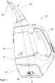
- FIG. 1 shows a side view of a handheld cleaning device 10.
- the handheld cleaning device comprises a housing 12.
- the housing 12 comprises a two-part clamshell arrangement.
- the clamshell arrangement may be fixed together with screws or glue or any other means for fastening the clamshells together.
- the housing 12 comprises a fluid tank 14 for receiving fluid entrained in an air flow received from a suction nozzle 16.
- the suction nozzle 16 is mounted in a cleaning head 18 and the cleaning head 18 is rotatably mounted to the housing 12.
- the housing 12 comprises an integral handle 20 and the handheld cleaning device suitable for the user to grip with their hand during operation. In this way the operable side of the handheld cleaning device 10 is on the side opposite the integral handle 20.
- the housing 12 comprises a removably mountable motor housing 22.
- the motor housing 22 is detachable from the housing 12 so that the electrical components of the handheld cleaning device can be completely separated from the housing 12. For example a user can remove the motor housing 22 and then wash the rest of the handheld cleaning device 10 without damaging the electrical components.
- the motor fan assembly 32 is integral with the housing 12 and the motor fan assembly 32 is mounted within the housing 12.
- the motor housing 22 comprises a catch mechanism (not shown) for releasably fixing the motor housing 22 to the housing 12.
- the catch mechanism comprises a release button (not shown) mounted on the housing for disengaging the catch and releasing the motor housing 22 from the housing 12.
- the motor housing 22 comprises a charging port 24 for charging a rechargeable battery 36.
- the charging port 24 is a micro USB port suitable for being charged from a standard 5V charger.
- the charging port 24 may be any suitable means for charging the internal rechargeable battery 36.
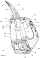
- Figure 2 shows a cross sectional side view of the handheld cleaning device.
- the motor housing 22 comprises a motor-fan assembly 32 for generating an air flow.
- the motor-fan assembly 32 is coupled to an electrical circuit 34 and powered by a rechargeable battery 36.
- the motor-fan assembly 32 is in fluid communication with the fluid tank 14 and the suction nozzle 16. In this way when the motor-fan assembly 32 operates air is drawn in from the suction nozzle 16, through the fluid tank 14 and towards the motor-fan assembly 32. Exhaust air is outputted from the motor housing 22 via air outlet holes in the hosing 12 (not shown).
- the motor fan assembly 32 is configured to be powerful enough to draw air and water together into the handheld cleaning device 10 via the suction nozzle 16.
- the inventors have realised that a motor fan assembly 32 capable of generating between 4 to 5 Air Watts is sufficient to suck both air and water into the fluid tank 14.
- the cleaning head 18 comprises a suction conduit 26 which couples the suction nozzle 16 with a dirty water inlet 28 of the fluid tank 14.
- the suction nozzle 16 is an opening in the cleaning head 18 for drawing air and water into the handheld cleaning device 10.
- the suction nozzle 16 comprises a flexible squeegee.
- the flexible squeegee aids capture of the excess water on a hard surface.
- the flexible squeegee may be rubber or any other suitable flexible material such as silicone.
- the suction nozzle 16 comprises two flexible rubber strips which are mounted either side of the opening.
- the flexible rubber stripes are mounted in a recess either side of the opening and the flexible rubber strips are removable so that they can be maintained and replaced.
- the suction nozzle in other embodiments is an opening in the hard shell of the cleaning head 18 without the flexible squeegee.
- the dirty water inlet 28 receives dirty water entrained in an air flow from the suction conduit 26.
- the dirty water inlet 28 is directed at a water separating element 30 and the water separating element 30 receives the dirty water and the air flow from the suction conduit 26.
- the air flow is incident on the water separating element 30, the kinetic energy of the dirty water entrained in the air flow is dissipated. This means that the dirty water drops out of the air flow and the dirty water collects in the bottom of the fluid tank 14.
- the dirty water can be removed from the dirty water tank by pouring the water out of drain port 42 once drain port plug 44 has been removed.
- the motor-fan assembly draws the air from the fluid tank 14 through a vacuum conduit 38.
- the air enters the vacuum conduit 38 at vacuum conduit opening 40.
- the vacuum conduit opening 40 comprises a lip 41 for shielding the opening 40 from stray droplets of water.
- the lip 41 is mounted on one side of the vacuum conduit 38 and the water separating element 30 is mounted on the other side of the vacuum conduit 38.
- the lip 41 which projects in an opposite direction to the water separating element 30. This further prevents stray droplets from being sucked into the vacuum conduit 38.
- the handheld cleaning device 10 also comprises a clean fluid tank 46 and a cleaning fluid delivery mechanism 55 connected thereto.
- the clean fluid tank comprises a cleaning fluid, such as clean water or a detergent.
- the clean fluid tank 46 is separate from the fluid tank 14 and the dirty water contained in the fluid tank 14 cannot contaminate the clean fluid tank 46. This means that the user does not have to recycle dirty water on the surface such as a window which means the surface is cleaned more efficiently.
- the cleaning fluid delivery mechanism 55 comprises the clean fluid tank 46 and a spray nozzle 48 which is coupled to the clean fluid tank 46 by a clean fluid conduit (not shown).
- the clean fluid conduit is a rubber hose or tube.
- the spray nozzle 48 is mounted in the wall of the housing 12.
- the spray nozzle 48 is mounted in a side of the housing 12 which is opposite the handle 20.
- the spray nozzle 48 of the cleaning fluid delivery mechanism 55 is actuated by trigger 50 which actuates a pump mechanism 51.
- the trigger 50 is mounted on the handle 20.
- the pump mechanism 51 is manually operated and when the user squeezes the trigger 50, the clean fluid is pumped along the clean fluid conduit to the spray nozzle 48.
- the pump mechanism 51 is a simple piston pump or a diaphragm pump.
- the trigger 50 is biased by spring 53 and is biased into an extended position as shown n Figure 2 . In this way the clean fluid is sprayed from the spray nozzle 48 when the user actuates the trigger 50.
- the pump mechanism can be any suitable means for pumping the clean fluid to the spray nozzle.
- the pump mechanism can be powered by a motorised pump selectively operated by the user.
- the suction head 18 By mounting the spray nozzle on the housing 12 and not the suction head 18, the suction head 18 is rotatable and the spray nozzle is operable when the suction head 18 is in any orientation. This also means that the clean fluid conduit does not have to have excess hosing or tubing to accommodate relative movement of the spray nozzle with respect to the housing 12.
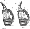
- Figures 3 and 4 show a side view of the handheld cleaning device 10 in two different modes.
- the handheld cleaning device 10 is shown with the cleaning head 18 in a first position.
- the suction nozzle 16 is in an operable position.
- the suction nozzle 16 is on the side of the housing which is opposite to the handle 20.
- the handle is on a rearwardly facing side of the housing and the suction nozzle is on a forwardly facing side of the housing.
- the cleaning head 18 also comprises a cleaning accessory 52.
- the cleaning head 18 comprises an attachment element 54 for mounting the cleaning accessory to the cleaning head 18.
- the cleaning accessory 52 is removable and there may be a hook and loop attachment means such as Velcro®.
- the cleaning accessory 52 can be removably fixed to the cleaning head by any suitable attachment means.
- the cleaning accessory 52 may releasably clip into the suction head 18.
- the cleaning accessory 52 may comprise holes for receiving screw fastenings for fastening the cleaning accessory 52 to the suction head 18.
- the cleaning accessory 52 may be one or more of a cloth, pad, foam pad, brush, scourer or any other suitable means for abrading, scraping or wiping dirt from a surface.
- the cleaning accessory 52 is on an opposite side of the cleaning head 18 to the suction nozzle opening. This means a rotation of 180 degrees is required to rotate the cleaning head between the two cleaning positions wherein either the suction nozzle 16 or the cleaning accessory is operable.
- Figure 4 shows the cleaning head 18 in a second position whereby the cleaning accessory 52 is in operable position.
- the cleaning head 18 When the cleaning head 18 is in the second position the cleaning accessory 52 is forwardly facing and engageable with the hard surface to be cleaned.
- the user In this position, the user can operated the trigger 50 to spray cleaning fluid from the nozzle 48 and the cleaning accessory 52 is wetted with the cleaning fluid to aid cleaning.
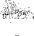
- Figure 5 shows a partial cross section of the handheld cleaning device at the point where the cleaning head 18 is mounted to the housing 12.
- Figures 6a and 6b show a partial perspective view of the cleaning head in different positions.
- the cleaning head 18 as shown in Figure 5 and Figure 6a is in the first position whereby the suction nozzle 16 is forwardly facing.
- the cleaning head 18 as shown in Figure 6b is in a position between the first and second positions.
- the cleaning head 18 is rotatably mounted on the housing 12.
- the cleaning head 18 comprises an annular flange 56 which engages in a reciprocal annular groove 58 in the housing 12.
- the annular flange 56 and annular groove 58 allow the cleaning head 18 to rotate about a longitudinal axis A-A of the housing 12.
- the vacuum tube 38 and the dirty water inlet 28 as shown in the figures are not aligned with the longitudinal axis A-A.
- the longitudinal axis suction conduit 26 at the housing 12 is substantially parallel but not coaxial with the longitudinal axis of the vacuum tube 38 or the longitudinal axis of the handheld cleaning device 10. This means that the suction conduit 26 of the cleaning head 18 does not align with the dirty water inlet.
- the handheld cleaning device 10 will only suck water and air into the fluid tank when the suction nozzle is in the operable position. In this way it is clear to the user which position the rotatable cleaning head 18 must be in for the handheld suction nozzle to work. For example a user is not able to orientate the cleaning head 18 with the cleaning accessory facing forwards and attempt to suck water in the suction nozzle 16 which would require the user to hold the handheld cleaning device in an awkward position to operate the suction nozzle 16 effectively.
- the longitudinal axis of the housing 12 is also the longitudinal axis of the handheld cleaning device 10.
- the longitudinal axis of the housing 12 is substantially aligned with the centre of the cleaning head.
- the longitudinal axis of the housing is substantially aligned with the longitudinal axis of the handle 20.
- the vacuum tube 38 and the dirty water inlet are also aligned with the longitudinal axis A-A.
- the axis of rotation of the cleaning 18 is substantially coaxial with the longitudinal axis of the handheld cleaning device 10 and the vacuum tube 38. This means that the suction conduit 26 of the cleaning head 18 will always remain aligned to the dirty water inlet 28 when the cleaning head rotates 18.
- the cleaning head 18 is rotatable about 360 degrees about the longitudinal axis A-A.
- the handheld cleaning device 10 comprises a locking mechanism 60.
- the locking mechanism 60 prevents rotation of the cleaning head 18 with respect to the housing 12 and prevents rotation of the cleaning head 18 between the first position and the second position.
- the locking mechanism 60 comprises an actuation button 62 for releasing the locking mechanism 60.
- the actuation button 62 is mechanically coupled to a locking arm 64 which engages with a reciprocal first recess 66 in annular flange 56 of the cleaning head 18.
- the locking arm 64 interlocks with the recess 66 and prevents rotation of the cleaning head 18 with respect to the housing 12.
- the cleaning head has a first recess 66 and a second recess 68 respectively associated with the first and second positions of the cleaning head 18.
- the first and second recesses 66, 68 are positioned diametrically opposite each other on the annular flange 54 to correspond with the first and second positions of the cleaning head 18. This means that the cleaning head 18 is rotatable about 180 degrees between the first position and the second position.
- the actuating button 62 and the locking arm 64 are biased to the locking position with spring 65. This means that when the user releases the locking mechanism 60, the cleaning head is free to rotate.
- the locking arm 64 will snap back in place when it is in proximity to the first or second recesses 66, 68. In this way the cleaning head 18 will automatically lock in either the first or second positions when the user rotates the cleaning head 18.
- annular flange 54 there are additional recesses (not shown) in the annular flange 54 which correspond to different positions between the first and second positions. This means that the cleaning head 18 can be releasably fixed in other positions such as 45 degree or 90 degree rotation of the cleaning head 18 from the first or second positions. Additional positions may help clean surfaces at different or unusual orientations.
- the user When the user wishes to rotate the cleaning head 18, the user depresses the actuating button 62, rotates the cleaning head 18 with respect to the housing 12.
- the locking mechanism 60 locks the cleaning head 18 in place when the user rotates the cleaning head 18 180 degrees about the longitudinal axis A-A.
- the locking mechanism is not necessary. Instead the coefficient of friction is increased between the cleaning head 18 and the housing 12 such that the cleaning head 18 may be rotated by hand, but held in position during operation by friction.
- a user can easily change whether the cleaning accessory or the suction nozzle is forward facing.
- the user does not need to put the handheld cleaning device down to rotate the cleaning head and this makes the handheld cleaning device particularly advantageous up ladders and other exposed environments.
- the rotatable cleaning head 18 may be releasable from the housing 12.
- the releasable cleaning head 18 is an optional feature and not required for the cleaning head 18 to rotate.
- Figure 7 shows a partial cross sectional view of the cleaning head 18.
- the cleaning head 18 is similar to the cleaning head 18 as described in reference to the previous embodiments.
- the cleaning head 18 is releasably mounted on a collar portion 76. When the cleaning head 18 is mounted to the collar portion 76, the cleaning head 18 rotates with the collar portion 76 when the cleaning head is rotated from the first position to the second position.
- the cleaning head 18 comprises a locking mechanism 71 for releasing the cleaning head 18 from the collar portion 76.
- the locking mechanism 71 comprises a release button 70 for releasing the cleaning head 18 from a reciprocal recess 74 in the collar portion 76.
- the release button 70 comprises an engagement element 72 engageable with the reciprocal recess 74 in the collar portion 76.
- the release button 70 and the engagement element 72 are sprung biased towards a position in which the engagement element 72 protrudes into the reciprocal recess 74.
- the user When the user wishes to the release the cleaning head 18, the user depresses the release button 70 and this moves the engagement element 72 clear of the recess 74. This means that the cleaning head 18 is no longer mounted to the collar portion 76 and the user can lift the cleaning head 18 free of the collar portion 76.
- the cleaning head 18 is removed by removing the cleaning head 18 substantially along the longitudinal axis of the handheld cleaning device.
- the release button 70 is positioned on the cleaning head 18 and this means the user can depress the release button 70 and remove the cleaning head 18 from the collar portion 76 with one hand.
- To replace the cleaning head 18 the use simply pushes the cleaning head 18 into the collar portion 76 until the engagement element 72 snaps into place in the recess 74.
- the cleaning head 18 comprises a recess and the collar portion 76 or the housing 12 comprises the release button and engagement element.
- the releasable cleaning head 18 is optional and in some embodiments the cleaning head 18 and the collar portion 76 are integral.
- the handheld cleaning device is a window washer or window washing device.
Description
- The present invention relates to a handheld cleaning device. In particular the present invention relates to a handheld cleaning device for cleaning hard, smooth surfaces.
- In the domestic environment it is desirable to maintain and clean hard smooth surfaces such as tiles and windows. Exterior windows may become dirty over time due to the grime of everyday life. Instead of cleaning the surfaces by hand some labour saving cleaning devices are known.
- One such device is shown in
EP2237711 which shows a window washing device having a motor fan assembly which sucks excess water on a hard surface through a suction nozzle and into a dirty water tank. This solution works if the hard surface is wet and the excess moisture sucked into the tank. However if the hard surface to be cleaned is dry, then the user must apply water. This may require the user to put the window washing device down whilst water is applied to the hard surface which is inconvenient if the user is working at height. -
US 5,590,439 shows an apparatus for cleaning by spreading liquid and by suction of the used liquid. The cleaning device comprises a spray nozzle and brush arrangement for deploying cleaning fluid from a separate reservoir on to the hard surface. The excess cleaning fluid is then sucked into the dirty water tank via the suction nozzle. The spray nozzle is mounted on a different side to the suction nozzle. This means that the user has to turn the whole cleaning device around to use the suction nozzle after deploying the cleaning fluid. However, the handle is profiled for a grip facing the spray nozzle and this means that the handle is awkward and uncomfortable to grip when the user uses the cleaning device to suck up excess liquid. -
FR 2 997 003 -
WO2008/065313 discloses a vacuum suction and cleaning apparatus comprising a nozzle, ventilation means, a clean water tank, and air/water separator, a recovery tank and a heating means. - Embodiments of the present invention aim to address the aforementioned problems.
- According to an aspect of the present invention there is a handheld cleaning device comprising: a housing having a handle for gripping the device; a motor-fan assembly for generating an air flow; a cleaning head comprising a suction nozzle in fluid communication with the motor-fan assembly and a cleaning accessory mounted on the cleaning head; and a fluid tank in fluid communication with the suction nozzle and the motor-fan assembly for receiving fluid from the suction nozzle in the air flow; wherein the cleaning head is rotatably mounted on the housing and the cleaning head is rotatable about a longitudinal axis of the housing between a first position in which the suction nozzle is in an operable position and a second position in which the cleaning accessory is in an operable position.
- This means that the handheld cleaning device can be held in the hand and the operable portion of the cleaning device can be rotated with respect to the housing without the user changing their grip of the cleaning device. This makes using the handheld cleaning device more comfortable and the user is less likely to drop the handheld cleaning device. By rotating the cleaning head about a longitudinal axis of the housing, the user is required to positively select either the suction nozzle or the cleaning accessory and is not able to accidentally operate the cleaning head in the first or second position.
- Preferably the handle is mounted on a first side of the housing and the operable position of the suction nozzle or the cleaning accessory is on a second side of the housing opposing the first side of the housing. This means that the operable position of the suction nozzle or the operable position of the cleaning accessory is visible to the user during operation.
- Preferably the handheld cleaning device comprises a locking mechanism for preventing the cleaning head from rotating between the first position and second positions. Preferably the locking mechanism comprises a moveable locking arm arranged to interlock with at least one recess. Preferably the locking mechanism comprises an actuating button mounted on the handle. This means that the cleaning head is easily unlocked into a position in which the cleaning head can be rotated. By positioning the release button on the handle, the button can easily be depressed with the thumb of the same hand that is gripping the handle.
- Preferably the cleaning head is arranged to be rotated about 180 degrees between the first and second positions.
- The handheld cleaning device comprises a cleaning fluid tank and a cleaning fluid delivery mechanism comprising a spray nozzle in fluid communication with the cleaning fluid tank. The spray nozzle is fixedly mounted on housing and the spray nozzle is mounted on the same side of the housing as the operable position of the suction nozzle or the cleaning accessory. Preferably the cleaning fluid delivery mechanism is actuated with a trigger mounted on the handle. Preferably the cleaning fluid tank is mounted in the handle. This means that the user can use handheld cleaning device and also deploy cleaning fluid without putting the handheld cleaning device down. By locating the trigger for actuating the cleaning fluid delivery mechanism on the handle, the user can easily hold the handheld cleaning device and spray cleaning fluid on to the dirty surface. Including the clean fluid tank in the handle saves space and reduces the overall size of the cleaning device.
- Preferably cleaning head comprises an attachment for mounting the cleaning accessory. Preferably the cleaning accessory is one or more of the following a pad, cloth, or brush. This means that the cleaning accessory can be replaced and maintained. Furthermore different cleaning accessories can be use for different cleaning purposes.
- Preferably the fluid tank comprises an inlet tube for receiving fluid from the suction nozzle and the longitudinal axis of the inlet tube is coaxial with the axis of rotation of the cleaning head. In this way the suction nozzle is capable of drawing air and water into the fluid tank irrespective of the orientation of the suction head with respect to the housing. Alternatively the fluid tank comprises an inlet tube for receiving fluid from the suction nozzle and the longitudinal axis of the inlet tube is substantially parallel but not coaxial with the axis of rotation of the cleaning head.
- Preferably the suction nozzle comprises a squeegee. A squeegee helps clean and remove liquid from hard surfaces such as windows or tiles.
- Preferably the cleaning head is releasable from the housing. Preferably there is a locking mechanism for releasing the cleaning head from the housing.
- Various other aspects and further embodiments are also described in the following detailed description and in the attached claims with reference to the accompanying drawings, in which:
-
Figure 1 shows a perspective view of the handheld cleaning device; -
Figure 2 shows cross sectional side view of the handheld cleaning device; -
Figure 3 and Figure 4 show side views of the handheld cleaning device in different configurations; -
Figure 5 shows a partial cross sectional side view of the handheld cleaning device; -
Figures 6a and 6b show partial perspective cut away views of the handheld cleaning device; and -
Figure 7 shows a partial cross sectional side view of the handheld cleaning device. -
Figure 1 shows a side view of ahandheld cleaning device 10. The handheld cleaning device comprises ahousing 12. Thehousing 12 comprises a two-part clamshell arrangement. The clamshell arrangement may be fixed together with screws or glue or any other means for fastening the clamshells together. - The
housing 12 comprises afluid tank 14 for receiving fluid entrained in an air flow received from asuction nozzle 16. Thesuction nozzle 16 is mounted in a cleaninghead 18 and thecleaning head 18 is rotatably mounted to thehousing 12. Thehousing 12 comprises anintegral handle 20 and the handheld cleaning device suitable for the user to grip with their hand during operation. In this way the operable side of thehandheld cleaning device 10 is on the side opposite theintegral handle 20. - The
housing 12 comprises a removablymountable motor housing 22. Themotor housing 22 is detachable from thehousing 12 so that the electrical components of the handheld cleaning device can be completely separated from thehousing 12. For example a user can remove themotor housing 22 and then wash the rest of thehandheld cleaning device 10 without damaging the electrical components. However in some alternative embodiments themotor fan assembly 32 is integral with thehousing 12 and themotor fan assembly 32 is mounted within thehousing 12. - The
motor housing 22 comprises a catch mechanism (not shown) for releasably fixing themotor housing 22 to thehousing 12. The catch mechanism comprises a release button (not shown) mounted on the housing for disengaging the catch and releasing themotor housing 22 from thehousing 12. Themotor housing 22 comprises a chargingport 24 for charging arechargeable battery 36. In some embodiments the chargingport 24 is a micro USB port suitable for being charged from a standard 5V charger. However in other embodiments the chargingport 24 may be any suitable means for charging the internalrechargeable battery 36. - Turning to
Figure 2 , the handheld cleaning device will now be discussed in further detail.Figure 2 shows a cross sectional side view of the handheld cleaning device. - The
motor housing 22 will now be discussed in further detail. Themotor housing 22 comprises a motor-fan assembly 32 for generating an air flow. The motor-fan assembly 32 is coupled to anelectrical circuit 34 and powered by arechargeable battery 36. The motor-fan assembly 32 is in fluid communication with thefluid tank 14 and thesuction nozzle 16. In this way when the motor-fan assembly 32 operates air is drawn in from thesuction nozzle 16, through thefluid tank 14 and towards the motor-fan assembly 32. Exhaust air is outputted from themotor housing 22 via air outlet holes in the hosing 12 (not shown). Themotor fan assembly 32 is configured to be powerful enough to draw air and water together into thehandheld cleaning device 10 via thesuction nozzle 16. The inventors have realised that amotor fan assembly 32 capable of generating between 4 to 5 Air Watts is sufficient to suck both air and water into thefluid tank 14. - The structure of the cleaning head will now be discussed in further detail. The cleaning
head 18 comprises asuction conduit 26 which couples thesuction nozzle 16 with adirty water inlet 28 of thefluid tank 14. Thesuction nozzle 16 is an opening in the cleaninghead 18 for drawing air and water into thehandheld cleaning device 10. In some embodiments thesuction nozzle 16 comprises a flexible squeegee. The flexible squeegee aids capture of the excess water on a hard surface. The flexible squeegee may be rubber or any other suitable flexible material such as silicone. In some embodiments thesuction nozzle 16 comprises two flexible rubber strips which are mounted either side of the opening. The flexible rubber stripes are mounted in a recess either side of the opening and the flexible rubber strips are removable so that they can be maintained and replaced. However the suction nozzle in other embodiments is an opening in the hard shell of the cleaninghead 18 without the flexible squeegee. - The
dirty water inlet 28 receives dirty water entrained in an air flow from thesuction conduit 26. Thedirty water inlet 28 is directed at awater separating element 30 and thewater separating element 30 receives the dirty water and the air flow from thesuction conduit 26. When the air flow is incident on thewater separating element 30, the kinetic energy of the dirty water entrained in the air flow is dissipated. This means that the dirty water drops out of the air flow and the dirty water collects in the bottom of thefluid tank 14. The dirty water can be removed from the dirty water tank by pouring the water out ofdrain port 42 oncedrain port plug 44 has been removed. - Once the dirty water has been removed from the air flow by the
water separating element 30, the motor-fan assembly draws the air from thefluid tank 14 through avacuum conduit 38. The air enters thevacuum conduit 38 atvacuum conduit opening 40. The vacuum conduit opening 40 comprises alip 41 for shielding theopening 40 from stray droplets of water. Thelip 41 is mounted on one side of thevacuum conduit 38 and thewater separating element 30 is mounted on the other side of thevacuum conduit 38. Thelip 41 which projects in an opposite direction to thewater separating element 30. This further prevents stray droplets from being sucked into thevacuum conduit 38. - The
handheld cleaning device 10 also comprises aclean fluid tank 46 and a cleaningfluid delivery mechanism 55 connected thereto. The clean fluid tank comprises a cleaning fluid, such as clean water or a detergent. - The
clean fluid tank 46 is separate from thefluid tank 14 and the dirty water contained in thefluid tank 14 cannot contaminate theclean fluid tank 46. This means that the user does not have to recycle dirty water on the surface such as a window which means the surface is cleaned more efficiently. - The cleaning
fluid delivery mechanism 55 comprises theclean fluid tank 46 and aspray nozzle 48 which is coupled to theclean fluid tank 46 by a clean fluid conduit (not shown). In some embodiments the clean fluid conduit is a rubber hose or tube. Thespray nozzle 48 is mounted in the wall of thehousing 12. Thespray nozzle 48 is mounted in a side of thehousing 12 which is opposite thehandle 20. Thespray nozzle 48 of the cleaningfluid delivery mechanism 55 is actuated bytrigger 50 which actuates apump mechanism 51. Thetrigger 50 is mounted on thehandle 20. Thepump mechanism 51 is manually operated and when the user squeezes thetrigger 50, the clean fluid is pumped along the clean fluid conduit to thespray nozzle 48. Thepump mechanism 51 is a simple piston pump or a diaphragm pump. Thetrigger 50 is biased byspring 53 and is biased into an extended position as shown nFigure 2 . In this way the clean fluid is sprayed from thespray nozzle 48 when the user actuates thetrigger 50. The other embodiments the pump mechanism can be any suitable means for pumping the clean fluid to the spray nozzle. For example the pump mechanism can be powered by a motorised pump selectively operated by the user. - By mounting the spray nozzle on the
housing 12 and not thesuction head 18, thesuction head 18 is rotatable and the spray nozzle is operable when thesuction head 18 is in any orientation. This also means that the clean fluid conduit does not have to have excess hosing or tubing to accommodate relative movement of the spray nozzle with respect to thehousing 12. - As mentioned above, the cleaning
head 18 is rotatably mounted onhousing 12. The cleaninghead 18 will now be discussed in further detail with respect toFigures 3 to 5 .Figures 3 and 4 show a side view of thehandheld cleaning device 10 in two different modes. - Turning the
Figure 3 thehandheld cleaning device 10 is shown with the cleaninghead 18 in a first position. In the first position thesuction nozzle 16 is in an operable position. In the operable position thesuction nozzle 16 is on the side of the housing which is opposite to thehandle 20. In other words the handle is on a rearwardly facing side of the housing and the suction nozzle is on a forwardly facing side of the housing. When thesuction nozzle 16 is forwardly facing thesuction nozzle 16 is engageable with the hard surface to be cleaned. - The cleaning
head 18 also comprises a cleaningaccessory 52. The cleaninghead 18 comprises anattachment element 54 for mounting the cleaning accessory to the cleaninghead 18. In some embodiments the cleaningaccessory 52 is removable and there may be a hook and loop attachment means such as Velcro®. In other embodiments the cleaningaccessory 52 can be removably fixed to the cleaning head by any suitable attachment means. For example the cleaningaccessory 52 may releasably clip into thesuction head 18. Alternatively the cleaningaccessory 52 may comprise holes for receiving screw fastenings for fastening the cleaningaccessory 52 to thesuction head 18. The cleaningaccessory 52 may be one or more of a cloth, pad, foam pad, brush, scourer or any other suitable means for abrading, scraping or wiping dirt from a surface. - The cleaning
accessory 52 is on an opposite side of the cleaninghead 18 to the suction nozzle opening. This means a rotation of 180 degrees is required to rotate the cleaning head between the two cleaning positions wherein either thesuction nozzle 16 or the cleaning accessory is operable. -
Figure 4 shows the cleaninghead 18 in a second position whereby the cleaningaccessory 52 is in operable position. When the cleaninghead 18 is in the second position the cleaningaccessory 52 is forwardly facing and engageable with the hard surface to be cleaned. In this position, the user can operated thetrigger 50 to spray cleaning fluid from thenozzle 48 and the cleaningaccessory 52 is wetted with the cleaning fluid to aid cleaning. - The mechanism for rotating the cleaning
head 18 will now be discussed in relation toFigures 5 ,6a and6b .Figure 5 shows a partial cross section of the handheld cleaning device at the point where the cleaninghead 18 is mounted to thehousing 12.Figures 6a and 6b show a partial perspective view of the cleaning head in different positions. The cleaninghead 18 as shown inFigure 5 andFigure 6a is in the first position whereby thesuction nozzle 16 is forwardly facing. The cleaninghead 18 as shown inFigure 6b is in a position between the first and second positions. - The cleaning
head 18 is rotatably mounted on thehousing 12. The cleaninghead 18 comprises anannular flange 56 which engages in a reciprocalannular groove 58 in thehousing 12. Theannular flange 56 andannular groove 58 allow the cleaninghead 18 to rotate about a longitudinal axis A-A of thehousing 12. Thevacuum tube 38 and thedirty water inlet 28 as shown in the figures are not aligned with the longitudinal axis A-A. The longitudinalaxis suction conduit 26 at thehousing 12 is substantially parallel but not coaxial with the longitudinal axis of thevacuum tube 38 or the longitudinal axis of thehandheld cleaning device 10. This means that thesuction conduit 26 of the cleaninghead 18 does not align with the dirty water inlet. This means that the when the cleaninghead 18 is in the first position, thesuction conduit 26 and thevacuum tube 38 are aligned. When the cleaninghead 18 is in the second position thesuction conduit 26 and thevacuum tube 38 are not aligned and air and water cannot be drawn into thefluid tank 14 by the motor fan assembly. This is because when thesuction conduit 26 and thevacuum tube 38 are not aligned not enough air is drawn through thesuction conduit 26 by themotor fan assembly 32. - This means that the
handheld cleaning device 10 will only suck water and air into the fluid tank when the suction nozzle is in the operable position. In this way it is clear to the user which position therotatable cleaning head 18 must be in for the handheld suction nozzle to work. For example a user is not able to orientate the cleaninghead 18 with the cleaning accessory facing forwards and attempt to suck water in thesuction nozzle 16 which would require the user to hold the handheld cleaning device in an awkward position to operate thesuction nozzle 16 effectively. - By rotating the cleaning
head 18 about the longitudinal axis of thehousing 12, the user will not accidentally move the cleaning head between the first position and the second position, even without a locking mechanism. When the use presses the cleaninghead 18 against the surface to be cleaned, there is substantially no turning moment on the cleaninghead 18 created about the rotational axis of the cleaninghead 18 because the entire length of the cleaninghead 18 will engage with the surface. The longitudinal axis of thehousing 12 is also the longitudinal axis of thehandheld cleaning device 10. In particular the longitudinal axis of thehousing 12 is substantially aligned with the centre of the cleaning head. Furthermore the longitudinal axis of the housing is substantially aligned with the longitudinal axis of thehandle 20. - In another embodiment the
vacuum tube 38 and the dirty water inlet are also aligned with the longitudinal axis A-A. In other words the axis of rotation of the cleaning 18 is substantially coaxial with the longitudinal axis of thehandheld cleaning device 10 and thevacuum tube 38. This means that thesuction conduit 26 of the cleaninghead 18 will always remain aligned to thedirty water inlet 28 when the cleaning head rotates 18. The cleaninghead 18 is rotatable about 360 degrees about the longitudinal axis A-A. - The
handheld cleaning device 10 comprises alocking mechanism 60. Thelocking mechanism 60 prevents rotation of the cleaninghead 18 with respect to thehousing 12 and prevents rotation of the cleaninghead 18 between the first position and the second position. Thelocking mechanism 60 comprises anactuation button 62 for releasing thelocking mechanism 60. Theactuation button 62 is mechanically coupled to alocking arm 64 which engages with a reciprocalfirst recess 66 inannular flange 56 of the cleaninghead 18. The lockingarm 64 interlocks with therecess 66 and prevents rotation of the cleaninghead 18 with respect to thehousing 12. The cleaning head has afirst recess 66 and asecond recess 68 respectively associated with the first and second positions of the cleaninghead 18. The first andsecond recesses annular flange 54 to correspond with the first and second positions of the cleaninghead 18. This means that the cleaninghead 18 is rotatable about 180 degrees between the first position and the second position. Theactuating button 62 and the lockingarm 64 are biased to the locking position withspring 65. This means that when the user releases thelocking mechanism 60, the cleaning head is free to rotate. The lockingarm 64 will snap back in place when it is in proximity to the first orsecond recesses head 18 will automatically lock in either the first or second positions when the user rotates the cleaninghead 18. - In some alternative embodiments there are additional recesses (not shown) in the
annular flange 54 which correspond to different positions between the first and second positions. This means that the cleaninghead 18 can be releasably fixed in other positions such as 45 degree or 90 degree rotation of the cleaninghead 18 from the first or second positions. Additional positions may help clean surfaces at different or unusual orientations. - When the user wishes to rotate the cleaning
head 18, the user depresses theactuating button 62, rotates the cleaninghead 18 with respect to thehousing 12. Thelocking mechanism 60 locks the cleaninghead 18 in place when the user rotates the cleaninghead 18 180 degrees about the longitudinal axis A-A. - In some embodiments the locking mechanism is not necessary. Instead the coefficient of friction is increased between the cleaning
head 18 and thehousing 12 such that the cleaninghead 18 may be rotated by hand, but held in position during operation by friction. - Advantageously by providing a
handheld cleaning device 10 with a cleaning head which is rotatable with respect to the housing, a user can easily change whether the cleaning accessory or the suction nozzle is forward facing. The user does not need to put the handheld cleaning device down to rotate the cleaning head and this makes the handheld cleaning device particularly advantageous up ladders and other exposed environments. - In some embodiments the
rotatable cleaning head 18 may be releasable from thehousing 12. Thereleasable cleaning head 18 is an optional feature and not required for the cleaninghead 18 to rotate.Figure 7 shows a partial cross sectional view of the cleaninghead 18. The cleaninghead 18 is similar to the cleaninghead 18 as described in reference to the previous embodiments. The cleaninghead 18 is releasably mounted on acollar portion 76. When the cleaninghead 18 is mounted to thecollar portion 76, the cleaninghead 18 rotates with thecollar portion 76 when the cleaning head is rotated from the first position to the second position. The cleaninghead 18 comprises alocking mechanism 71 for releasing the cleaninghead 18 from thecollar portion 76. Thelocking mechanism 71 comprises arelease button 70 for releasing the cleaninghead 18 from areciprocal recess 74 in thecollar portion 76. Therelease button 70 comprises anengagement element 72 engageable with thereciprocal recess 74 in thecollar portion 76. Therelease button 70 and theengagement element 72 are sprung biased towards a position in which theengagement element 72 protrudes into thereciprocal recess 74. - When the user wishes to the release the cleaning
head 18, the user depresses therelease button 70 and this moves theengagement element 72 clear of therecess 74. This means that the cleaninghead 18 is no longer mounted to thecollar portion 76 and the user can lift the cleaninghead 18 free of thecollar portion 76. The cleaninghead 18 is removed by removing the cleaninghead 18 substantially along the longitudinal axis of the handheld cleaning device. Therelease button 70 is positioned on the cleaninghead 18 and this means the user can depress therelease button 70 and remove the cleaninghead 18 from thecollar portion 76 with one hand. To replace the cleaninghead 18 the use simply pushes the cleaninghead 18 into thecollar portion 76 until theengagement element 72 snaps into place in therecess 74. In an alternative embodiment the cleaninghead 18 comprises a recess and thecollar portion 76 or thehousing 12 comprises the release button and engagement element. - As mentioned above the releasable cleaning
head 18 is optional and in some embodiments the cleaninghead 18 and thecollar portion 76 are integral. - In some embodiment the handheld cleaning device is a window washer or window washing device.
Claims (13)
- A handheld cleaning device (10) comprising:a housing (12) having a handle (20) for gripping the device;a motor-fan assembly (32) for generating an air flow;a cleaning head (18) comprising a suction nozzle (16) in fluid communication with the motor-fan assembly (32) and a cleaning accessory (52) mounted on the cleaning head; anda fluid tank (14) in fluid communication with the suction nozzle (16) and the motor-fan assembly (32) for receiving fluid from the suction nozzle (16) in the air flow,wherein the cleaning head (18) is rotatably mounted on the housing (12) and the cleaning head (18) is rotatable about a longitudinal axis of the housing (12) between a first position in which the suction nozzle (16) is in an operable position and a second position in which the cleaning accessory (52) is in an operable position,characterised in that the handheld cleaning device comprises a cleaning fluid tank (14) and cleaning fluid delivery mechanism (55) comprising a spray nozzle (48) in fluid communication with the cleaning fluid tank (14), andwherein the spray nozzle (48) is fixedly mounted on housing (12) and the spray nozzle (48) is mounted on the same side of the housing (12) as the operable position of the suction nozzle (16) or the cleaning accessory (52).
- A handheld cleaning device according to claim 1 wherein the handle (20) is mounted on a first side of the housing (12) and the operable position of the suction nozzle (16) or the cleaning accessory (52) is on a second side of the housing (12) opposing the first side of the housing (12).
- A handheld cleaning device according to claims 1 or 2 wherein the handheld cleaning device (10) comprises a locking mechanism for preventing the cleaning head (18) from rotating between the first position and second positions.
- A handheld cleaning device according to claim 3 wherein the locking mechanism (60) comprises a moveable locking arm (64) arranged to interlock with at least one recess (66).
- A handheld cleaning device according to claims 3 or 4 wherein the locking mechanism (60) comprises an actuating button (62) mounted on the handle (20).
- A handheld cleaning device according to any of the preceding claims wherein the cleaning head (18) is arranged to be rotated about 180 degrees between the first and second positions.
- A handheld cleaning device according to any of the preceding claims wherein the cleaning fluid delivery mechanism (55) is actuated with a trigger (50) mounted on the handle (20).
- A handheld cleaning device according to any of the preceding claims wherein the cleaning fluid tank (14) is mounted in the handle (20).
- A handheld cleaning device according to any of the preceding claims wherein the cleaning head (18) comprises an attachment (54) for mounting the cleaning accessory (52).
- A handheld cleaning device according to any of the preceding claims wherein the cleaning accessory (52) is one or more of the following a pad, cloth, or brush.
- A handheld cleaning device according to any of the preceding claims wherein the fluid tank (14) comprises an inlet tube for receiving fluid from the suction nozzle (16) and the longitudinal axis of the inlet tube is coaxial with the axis of rotation of the cleaning head (18).
- A handheld cleaning device according to any of claims 1 to 10 wherein the fluid tank (14) comprises an inlet tube for receiving fluid from the suction nozzle (16) and the longitudinal axis of the inlet tube is substantially parallel but not coaxial with the axis of rotation of the cleaning head (18).
- A handheld cleaning device wherein the suction nozzle (16) comprises a squeegee.
Priority Applications (5)
| Application Number | Priority Date | Filing Date | Title |
|---|---|---|---|
| EP14183496.0A EP2992798B1 (en) | 2014-09-04 | 2014-09-04 | Handheld cleaning device |
| US14/793,299 US20160066756A1 (en) | 2014-09-04 | 2015-07-07 | Handheld cleaning device |
| AU2015221476A AU2015221476A1 (en) | 2014-09-04 | 2015-09-02 | Handheld cleaning device |
| JP2015173476A JP2016055167A (en) | 2014-09-04 | 2015-09-03 | Handheld cleaning device |
| CN201510561205.1A CN105395139A (en) | 2014-09-04 | 2015-09-06 | Handheld Cleaning Device |
Applications Claiming Priority (1)
| Application Number | Priority Date | Filing Date | Title |
|---|---|---|---|
| EP14183496.0A EP2992798B1 (en) | 2014-09-04 | 2014-09-04 | Handheld cleaning device |
Publications (2)
| Publication Number | Publication Date |
|---|---|
| EP2992798A1 EP2992798A1 (en) | 2016-03-09 |
| EP2992798B1 true EP2992798B1 (en) | 2019-05-08 |
Family
ID=51564438
Family Applications (1)
| Application Number | Title | Priority Date | Filing Date |
|---|---|---|---|
| EP14183496.0A Active EP2992798B1 (en) | 2014-09-04 | 2014-09-04 | Handheld cleaning device |
Country Status (5)
| Country | Link |
|---|---|
| US (1) | US20160066756A1 (en) |
| EP (1) | EP2992798B1 (en) |
| JP (1) | JP2016055167A (en) |
| CN (1) | CN105395139A (en) |
| AU (1) | AU2015221476A1 (en) |
Families Citing this family (13)
| Publication number | Priority date | Publication date | Assignee | Title |
|---|---|---|---|---|
| USD771331S1 (en) * | 2015-04-10 | 2016-11-08 | Mike Chaklos | Computer cleaner |
| EP3426118A1 (en) * | 2016-03-08 | 2019-01-16 | Alfred Kärcher SE & Co. KG | Hand-held suction device |
| JP6739532B2 (en) * | 2016-07-15 | 2020-08-12 | 三菱電機株式会社 | Vacuum cleaner and hand dryer |
| KR102476535B1 (en) * | 2016-09-13 | 2022-12-09 | 엘지전자 주식회사 | Remaining water suction device |
| GB2566070A (en) * | 2017-09-03 | 2019-03-06 | John Brown Allan | Portable vacuum window cleaning device |
| DE102017121208A1 (en) * | 2017-09-13 | 2019-03-14 | Alfred Kärcher SE & Co. KG | Surface cleaning device |
| DE102017121209A1 (en) | 2017-09-13 | 2019-03-14 | Alfred Kärcher SE & Co. KG | Surface cleaning device |
| US20190082919A1 (en) | 2017-09-15 | 2019-03-21 | Omachron Intellectual Property Inc. | Surface cleaning apparatus |
| JP7056291B2 (en) * | 2018-03-23 | 2022-04-19 | 三菱電機株式会社 | Vacuum cleaner |
| US11433437B2 (en) * | 2018-04-13 | 2022-09-06 | James T. Pierson | Coating removal system |
| JP7144980B2 (en) * | 2018-06-20 | 2022-09-30 | 株式会社マキタ | Cleaner |
| CN112386159A (en) * | 2019-08-11 | 2021-02-23 | 苏州谷为电器有限公司 | Hand-held type surface cleaning device |
| US20240032757A1 (en) * | 2022-07-26 | 2024-02-01 | Bissell Inc. | Extraction cleaner systems, methods, and devices with disposable absorbent pads in recovery pathway |
Family Cites Families (21)
| Publication number | Priority date | Publication date | Assignee | Title |
|---|---|---|---|---|
| US2885716A (en) * | 1954-11-04 | 1959-05-12 | Electrolux Corp | Double purpose suction cleaning nozzle |
| US2867835A (en) * | 1956-12-28 | 1959-01-13 | Jr Charles K Brown | Double acting vacuum and scrubbing head |
| US3254360A (en) * | 1961-11-13 | 1966-06-07 | Whirlpool Co | Window washer with vacuum pick-up |
| US4864681A (en) * | 1988-06-20 | 1989-09-12 | Emerson Electric Co. | Multi-purpose floor cleaning tool |
| DE4125866A1 (en) * | 1991-08-03 | 1993-02-04 | Kaercher Gmbh & Co Alfred | HARD SURFACE WIPER, ESPECIALLY WINDOW WIPER |
| FR2715054B1 (en) | 1994-01-14 | 1996-03-15 | Famulus | Cleaning device by spreading cleaning liquid and by suction of used liquid. |
| US5599401A (en) * | 1994-08-04 | 1997-02-04 | Jancar Industries, Inc. | Portable, hand-held, self-contained multi-surface, hydro-cleaning apparatus |
| US5652996A (en) * | 1995-12-01 | 1997-08-05 | The Hoover Company | Hand held cleaner with swiveling nozzle |
| DE19651477C2 (en) * | 1996-12-11 | 2000-07-20 | Thomas Robert Metall Elektro | Electric handheld vacuum cleaner |
| WO1998029020A2 (en) * | 1996-12-31 | 1998-07-09 | Royal Appliance Mfg Co. | Cordless wet mop and vacuum assembly |
| US6968593B1 (en) * | 2001-08-14 | 2005-11-29 | Bissell Homecare, Inc. | Hand-held deep cleaner |
| US7478455B2 (en) * | 2003-01-10 | 2009-01-20 | Lisa Ann Heim | Hand-held clothing spot remover |
| CN2815256Y (en) * | 2005-08-26 | 2006-09-13 | 陈朗 | Glass wind scraper capable of steering head |
| FR2909275B1 (en) * | 2006-12-01 | 2010-12-17 | Gerard Curien | APPARATUS FOR SUCTION AND CLEANING WATER AND / OR DUST |
| DE102008004965B3 (en) | 2008-01-11 | 2009-05-14 | Alfred Kärcher Gmbh & Co. Kg | Portable hard surface suction device |
| US20110005025A1 (en) * | 2009-07-10 | 2011-01-13 | Thomas Carrington | Cleaning system |
| JP5124626B2 (en) * | 2010-08-16 | 2013-01-23 | 正史 二瓶 | Window cleaning tools |
| FR2997003B1 (en) * | 2012-10-23 | 2015-05-01 | Ecodrop | CLEANING APPARATUS |
| CN102920398B (en) * | 2012-11-07 | 2015-06-10 | 刘世君 | Water-sucking type cleaner with water spraying function |
| KR20140144864A (en) * | 2013-06-12 | 2014-12-22 | 삼성전자주식회사 | Vacuum Cleaner |
| CN103349527B (en) * | 2013-07-10 | 2016-06-22 | 奉化市威优特电器有限公司 | Electric window scraping machine improves structure |
-
2014
- 2014-09-04 EP EP14183496.0A patent/EP2992798B1/en active Active
-
2015
- 2015-07-07 US US14/793,299 patent/US20160066756A1/en not_active Abandoned
- 2015-09-02 AU AU2015221476A patent/AU2015221476A1/en not_active Abandoned
- 2015-09-03 JP JP2015173476A patent/JP2016055167A/en active Pending
- 2015-09-06 CN CN201510561205.1A patent/CN105395139A/en active Pending
Non-Patent Citations (1)
| Title |
|---|
| None * |
Also Published As
| Publication number | Publication date |
|---|---|
| CN105395139A (en) | 2016-03-16 |
| AU2015221476A1 (en) | 2016-03-24 |
| EP2992798A1 (en) | 2016-03-09 |
| US20160066756A1 (en) | 2016-03-10 |
| JP2016055167A (en) | 2016-04-21 |
Similar Documents
| Publication | Publication Date | Title |
|---|---|---|
| EP2992798B1 (en) | Handheld cleaning device | |
| KR200497014Y1 (en) | Surface cleaning apparatus | |
| US11457790B2 (en) | Floor cleaning machine | |
| RU2312580C2 (en) | Vacuum cleaner with cleaning head | |
| JP4859988B2 (en) | Inhalation-type wet jet mop | |
| TWI251049B (en) | Portable electric pool cleaner | |
| US8220109B2 (en) | Handheld pet hair vacuum cleaner | |
| US9743819B2 (en) | Floor mop with concentrated cleaning feature | |
| JP2006516423A (en) | Inhalation-type wet jet mop | |
| US10188250B2 (en) | Floor cleaning tool having a mechanically operated pump | |
| US11284770B2 (en) | Hard surface cleaning device | |
| CN210055872U (en) | Improved handheld dust collector | |
| US20110005025A1 (en) | Cleaning system | |
| CN215937267U (en) | Cleaning device | |
| GB2514153A (en) | Hard surface cleaning device | |
| WO2004100754A1 (en) | Arrangement for a floor mop provided with a handle | |
| CN216628423U (en) | Host computer and surface cleaning equipment | |
| KR100539759B1 (en) | Multi cleaner | |
| GB2468797A (en) | Handheld vacuum cleaner | |
| JP3135692U (en) | Suction port fitting | |
| AU2013237669B2 (en) | Handheld pet hair vacuum cleaner | |
| JP2001149870A (en) | Cleaner for clean room | |
| KR19990000058A (en) | vacuum cleaner | |
| CN115702767A (en) | Host computer and surface cleaning equipment | |
| KR100595582B1 (en) | Well for multi cleaner |
Legal Events
| Date | Code | Title | Description |
|---|---|---|---|
| PUAI | Public reference made under article 153(3) epc to a published international application that has entered the european phase |
Free format text: ORIGINAL CODE: 0009012 |
|
| AK | Designated contracting states |
Kind code of ref document: A1 Designated state(s): AL AT BE BG CH CY CZ DE DK EE ES FI FR GB GR HR HU IE IS IT LI LT LU LV MC MK MT NL NO PL PT RO RS SE SI SK SM TR |
|
| AX | Request for extension of the european patent |
Extension state: BA ME |
|
| 17P | Request for examination filed |
Effective date: 20160824 |
|
| RBV | Designated contracting states (corrected) |
Designated state(s): AL AT BE BG CH CY CZ DE DK EE ES FI FR GB GR HR HU IE IS IT LI LT LU LV MC MK MT NL NO PL PT RO RS SE SI SK SM TR |
|
| STAA | Information on the status of an ep patent application or granted ep patent |
Free format text: STATUS: EXAMINATION IS IN PROGRESS |
|
| 17Q | First examination report despatched |
Effective date: 20170518 |
|
| GRAP | Despatch of communication of intention to grant a patent |
Free format text: ORIGINAL CODE: EPIDOSNIGR1 |
|
| STAA | Information on the status of an ep patent application or granted ep patent |
Free format text: STATUS: GRANT OF PATENT IS INTENDED |
|
| INTG | Intention to grant announced |
Effective date: 20190125 |
|
| GRAS | Grant fee paid |
Free format text: ORIGINAL CODE: EPIDOSNIGR3 |
|
| GRAA | (expected) grant |
Free format text: ORIGINAL CODE: 0009210 |
|
| STAA | Information on the status of an ep patent application or granted ep patent |
Free format text: STATUS: THE PATENT HAS BEEN GRANTED |
|
| AK | Designated contracting states |
Kind code of ref document: B1 Designated state(s): AL AT BE BG CH CY CZ DE DK EE ES FI FR GB GR HR HU IE IS IT LI LT LU LV MC MK MT NL NO PL PT RO RS SE SI SK SM TR |
|
| REG | Reference to a national code |
Ref country code: GB Ref legal event code: FG4D |
|
| REG | Reference to a national code |
Ref country code: CH Ref legal event code: EP Ref country code: AT Ref legal event code: REF Ref document number: 1128867 Country of ref document: AT Kind code of ref document: T Effective date: 20190515 |
|
| REG | Reference to a national code |
Ref country code: IE Ref legal event code: FG4D |
|
| REG | Reference to a national code |
Ref country code: DE Ref legal event code: R096 Ref document number: 602014046165 Country of ref document: DE |
|
| REG | Reference to a national code |
Ref country code: NL Ref legal event code: MP Effective date: 20190508 |
|
| REG | Reference to a national code |
Ref country code: LT Ref legal event code: MG4D |
|
| PG25 | Lapsed in a contracting state [announced via postgrant information from national office to epo] |
Ref country code: LT Free format text: LAPSE BECAUSE OF FAILURE TO SUBMIT A TRANSLATION OF THE DESCRIPTION OR TO PAY THE FEE WITHIN THE PRESCRIBED TIME-LIMIT Effective date: 20190508 Ref country code: ES Free format text: LAPSE BECAUSE OF FAILURE TO SUBMIT A TRANSLATION OF THE DESCRIPTION OR TO PAY THE FEE WITHIN THE PRESCRIBED TIME-LIMIT Effective date: 20190508 Ref country code: NL Free format text: LAPSE BECAUSE OF FAILURE TO SUBMIT A TRANSLATION OF THE DESCRIPTION OR TO PAY THE FEE WITHIN THE PRESCRIBED TIME-LIMIT Effective date: 20190508 Ref country code: SE Free format text: LAPSE BECAUSE OF FAILURE TO SUBMIT A TRANSLATION OF THE DESCRIPTION OR TO PAY THE FEE WITHIN THE PRESCRIBED TIME-LIMIT Effective date: 20190508 Ref country code: HR Free format text: LAPSE BECAUSE OF FAILURE TO SUBMIT A TRANSLATION OF THE DESCRIPTION OR TO PAY THE FEE WITHIN THE PRESCRIBED TIME-LIMIT Effective date: 20190508 Ref country code: PT Free format text: LAPSE BECAUSE OF FAILURE TO SUBMIT A TRANSLATION OF THE DESCRIPTION OR TO PAY THE FEE WITHIN THE PRESCRIBED TIME-LIMIT Effective date: 20190908 Ref country code: NO Free format text: LAPSE BECAUSE OF FAILURE TO SUBMIT A TRANSLATION OF THE DESCRIPTION OR TO PAY THE FEE WITHIN THE PRESCRIBED TIME-LIMIT Effective date: 20190808 Ref country code: AL Free format text: LAPSE BECAUSE OF FAILURE TO SUBMIT A TRANSLATION OF THE DESCRIPTION OR TO PAY THE FEE WITHIN THE PRESCRIBED TIME-LIMIT Effective date: 20190508 Ref country code: FI Free format text: LAPSE BECAUSE OF FAILURE TO SUBMIT A TRANSLATION OF THE DESCRIPTION OR TO PAY THE FEE WITHIN THE PRESCRIBED TIME-LIMIT Effective date: 20190508 |
|
| PG25 | Lapsed in a contracting state [announced via postgrant information from national office to epo] |
Ref country code: RS Free format text: LAPSE BECAUSE OF FAILURE TO SUBMIT A TRANSLATION OF THE DESCRIPTION OR TO PAY THE FEE WITHIN THE PRESCRIBED TIME-LIMIT Effective date: 20190508 Ref country code: LV Free format text: LAPSE BECAUSE OF FAILURE TO SUBMIT A TRANSLATION OF THE DESCRIPTION OR TO PAY THE FEE WITHIN THE PRESCRIBED TIME-LIMIT Effective date: 20190508 Ref country code: GR Free format text: LAPSE BECAUSE OF FAILURE TO SUBMIT A TRANSLATION OF THE DESCRIPTION OR TO PAY THE FEE WITHIN THE PRESCRIBED TIME-LIMIT Effective date: 20190809 Ref country code: BG Free format text: LAPSE BECAUSE OF FAILURE TO SUBMIT A TRANSLATION OF THE DESCRIPTION OR TO PAY THE FEE WITHIN THE PRESCRIBED TIME-LIMIT Effective date: 20190808 |
|
| REG | Reference to a national code |
Ref country code: AT Ref legal event code: MK05 Ref document number: 1128867 Country of ref document: AT Kind code of ref document: T Effective date: 20190508 |
|
| PG25 | Lapsed in a contracting state [announced via postgrant information from national office to epo] |
Ref country code: RO Free format text: LAPSE BECAUSE OF FAILURE TO SUBMIT A TRANSLATION OF THE DESCRIPTION OR TO PAY THE FEE WITHIN THE PRESCRIBED TIME-LIMIT Effective date: 20190508 Ref country code: CZ Free format text: LAPSE BECAUSE OF FAILURE TO SUBMIT A TRANSLATION OF THE DESCRIPTION OR TO PAY THE FEE WITHIN THE PRESCRIBED TIME-LIMIT Effective date: 20190508 Ref country code: SK Free format text: LAPSE BECAUSE OF FAILURE TO SUBMIT A TRANSLATION OF THE DESCRIPTION OR TO PAY THE FEE WITHIN THE PRESCRIBED TIME-LIMIT Effective date: 20190508 Ref country code: DK Free format text: LAPSE BECAUSE OF FAILURE TO SUBMIT A TRANSLATION OF THE DESCRIPTION OR TO PAY THE FEE WITHIN THE PRESCRIBED TIME-LIMIT Effective date: 20190508 Ref country code: AT Free format text: LAPSE BECAUSE OF FAILURE TO SUBMIT A TRANSLATION OF THE DESCRIPTION OR TO PAY THE FEE WITHIN THE PRESCRIBED TIME-LIMIT Effective date: 20190508 Ref country code: EE Free format text: LAPSE BECAUSE OF FAILURE TO SUBMIT A TRANSLATION OF THE DESCRIPTION OR TO PAY THE FEE WITHIN THE PRESCRIBED TIME-LIMIT Effective date: 20190508 |
|
| REG | Reference to a national code |
Ref country code: DE Ref legal event code: R097 Ref document number: 602014046165 Country of ref document: DE |
|
| PG25 | Lapsed in a contracting state [announced via postgrant information from national office to epo] |
Ref country code: IT Free format text: LAPSE BECAUSE OF FAILURE TO SUBMIT A TRANSLATION OF THE DESCRIPTION OR TO PAY THE FEE WITHIN THE PRESCRIBED TIME-LIMIT Effective date: 20190508 Ref country code: SM Free format text: LAPSE BECAUSE OF FAILURE TO SUBMIT A TRANSLATION OF THE DESCRIPTION OR TO PAY THE FEE WITHIN THE PRESCRIBED TIME-LIMIT Effective date: 20190508 |
|
| PLBE | No opposition filed within time limit |
Free format text: ORIGINAL CODE: 0009261 |
|
| STAA | Information on the status of an ep patent application or granted ep patent |
Free format text: STATUS: NO OPPOSITION FILED WITHIN TIME LIMIT |
|
| PG25 | Lapsed in a contracting state [announced via postgrant information from national office to epo] |
Ref country code: TR Free format text: LAPSE BECAUSE OF FAILURE TO SUBMIT A TRANSLATION OF THE DESCRIPTION OR TO PAY THE FEE WITHIN THE PRESCRIBED TIME-LIMIT Effective date: 20190508 |
|
| 26N | No opposition filed |
Effective date: 20200211 |
|
| PG25 | Lapsed in a contracting state [announced via postgrant information from national office to epo] |
Ref country code: PL Free format text: LAPSE BECAUSE OF FAILURE TO SUBMIT A TRANSLATION OF THE DESCRIPTION OR TO PAY THE FEE WITHIN THE PRESCRIBED TIME-LIMIT Effective date: 20190508 |
|
| PG25 | Lapsed in a contracting state [announced via postgrant information from national office to epo] |
Ref country code: MC Free format text: LAPSE BECAUSE OF FAILURE TO SUBMIT A TRANSLATION OF THE DESCRIPTION OR TO PAY THE FEE WITHIN THE PRESCRIBED TIME-LIMIT Effective date: 20190508 Ref country code: SI Free format text: LAPSE BECAUSE OF FAILURE TO SUBMIT A TRANSLATION OF THE DESCRIPTION OR TO PAY THE FEE WITHIN THE PRESCRIBED TIME-LIMIT Effective date: 20190508 |
|
| REG | Reference to a national code |
Ref country code: CH Ref legal event code: PL |
|
| PG25 | Lapsed in a contracting state [announced via postgrant information from national office to epo] |
Ref country code: CH Free format text: LAPSE BECAUSE OF NON-PAYMENT OF DUE FEES Effective date: 20190930 Ref country code: IE Free format text: LAPSE BECAUSE OF NON-PAYMENT OF DUE FEES Effective date: 20190904 Ref country code: LU Free format text: LAPSE BECAUSE OF NON-PAYMENT OF DUE FEES Effective date: 20190904 Ref country code: LI Free format text: LAPSE BECAUSE OF NON-PAYMENT OF DUE FEES Effective date: 20190930 |
|
| REG | Reference to a national code |
Ref country code: BE Ref legal event code: MM Effective date: 20190930 |
|
| PG25 | Lapsed in a contracting state [announced via postgrant information from national office to epo] |
Ref country code: BE Free format text: LAPSE BECAUSE OF NON-PAYMENT OF DUE FEES Effective date: 20190930 |
|
| PG25 | Lapsed in a contracting state [announced via postgrant information from national office to epo] |
Ref country code: FR Free format text: LAPSE BECAUSE OF NON-PAYMENT OF DUE FEES Effective date: 20190930 |
|
| PG25 | Lapsed in a contracting state [announced via postgrant information from national office to epo] |
Ref country code: CY Free format text: LAPSE BECAUSE OF FAILURE TO SUBMIT A TRANSLATION OF THE DESCRIPTION OR TO PAY THE FEE WITHIN THE PRESCRIBED TIME-LIMIT Effective date: 20190508 |
|
| PG25 | Lapsed in a contracting state [announced via postgrant information from national office to epo] |
Ref country code: IS Free format text: LAPSE BECAUSE OF FAILURE TO SUBMIT A TRANSLATION OF THE DESCRIPTION OR TO PAY THE FEE WITHIN THE PRESCRIBED TIME-LIMIT Effective date: 20190908 |
|
| PG25 | Lapsed in a contracting state [announced via postgrant information from national office to epo] |
Ref country code: MT Free format text: LAPSE BECAUSE OF FAILURE TO SUBMIT A TRANSLATION OF THE DESCRIPTION OR TO PAY THE FEE WITHIN THE PRESCRIBED TIME-LIMIT Effective date: 20190508 Ref country code: HU Free format text: LAPSE BECAUSE OF FAILURE TO SUBMIT A TRANSLATION OF THE DESCRIPTION OR TO PAY THE FEE WITHIN THE PRESCRIBED TIME-LIMIT; INVALID AB INITIO Effective date: 20140904 |
|
| PG25 | Lapsed in a contracting state [announced via postgrant information from national office to epo] |
Ref country code: MK Free format text: LAPSE BECAUSE OF FAILURE TO SUBMIT A TRANSLATION OF THE DESCRIPTION OR TO PAY THE FEE WITHIN THE PRESCRIBED TIME-LIMIT Effective date: 20190508 |
|
| PGFP | Annual fee paid to national office [announced via postgrant information from national office to epo] |
Ref country code: GB Payment date: 20230713 Year of fee payment: 10 |
|
| PGFP | Annual fee paid to national office [announced via postgrant information from national office to epo] |
Ref country code: DE Payment date: 20230712 Year of fee payment: 10 |