EP2992687B1 - Microphone array for acoustic source separation - Google Patents
Microphone array for acoustic source separation Download PDFInfo
- Publication number
- EP2992687B1 EP2992687B1 EP14721931.5A EP14721931A EP2992687B1 EP 2992687 B1 EP2992687 B1 EP 2992687B1 EP 14721931 A EP14721931 A EP 14721931A EP 2992687 B1 EP2992687 B1 EP 2992687B1
- Authority
- EP
- European Patent Office
- Prior art keywords
- sensors
- sound
- microphones
- support means
- array
- Prior art date
- Legal status (The legal status is an assumption and is not a legal conclusion. Google has not performed a legal analysis and makes no representation as to the accuracy of the status listed.)
- Active
Links
Images




Classifications
-
- H—ELECTRICITY
- H04—ELECTRIC COMMUNICATION TECHNIQUE
- H04R—LOUDSPEAKERS, MICROPHONES, GRAMOPHONE PICK-UPS OR LIKE ACOUSTIC ELECTROMECHANICAL TRANSDUCERS; ELECTRIC HEARING AIDS; PUBLIC ADDRESS SYSTEMS
- H04R5/00—Stereophonic arrangements
- H04R5/027—Spatial or constructional arrangements of microphones, e.g. in dummy heads
-
- G—PHYSICS
- G10—MUSICAL INSTRUMENTS; ACOUSTICS
- G10K—SOUND-PRODUCING DEVICES; METHODS OR DEVICES FOR PROTECTING AGAINST, OR FOR DAMPING, NOISE OR OTHER ACOUSTIC WAVES IN GENERAL; ACOUSTICS NOT OTHERWISE PROVIDED FOR
- G10K11/00—Methods or devices for transmitting, conducting or directing sound in general; Methods or devices for protecting against, or for damping, noise or other acoustic waves in general
- G10K11/002—Devices for damping, suppressing, obstructing or conducting sound in acoustic devices
-
- H—ELECTRICITY
- H04—ELECTRIC COMMUNICATION TECHNIQUE
- H04M—TELEPHONIC COMMUNICATION
- H04M1/00—Substation equipment, e.g. for use by subscribers
- H04M1/02—Constructional features of telephone sets
- H04M1/03—Constructional features of telephone transmitters or receivers, e.g. telephone hand-sets
-
- H—ELECTRICITY
- H04—ELECTRIC COMMUNICATION TECHNIQUE
- H04R—LOUDSPEAKERS, MICROPHONES, GRAMOPHONE PICK-UPS OR LIKE ACOUSTIC ELECTROMECHANICAL TRANSDUCERS; ELECTRIC HEARING AIDS; PUBLIC ADDRESS SYSTEMS
- H04R1/00—Details of transducers, loudspeakers or microphones
- H04R1/02—Casings; Cabinets ; Supports therefor; Mountings therein
-
- H—ELECTRICITY
- H04—ELECTRIC COMMUNICATION TECHNIQUE
- H04R—LOUDSPEAKERS, MICROPHONES, GRAMOPHONE PICK-UPS OR LIKE ACOUSTIC ELECTROMECHANICAL TRANSDUCERS; ELECTRIC HEARING AIDS; PUBLIC ADDRESS SYSTEMS
- H04R1/00—Details of transducers, loudspeakers or microphones
- H04R1/02—Casings; Cabinets ; Supports therefor; Mountings therein
- H04R1/026—Supports for loudspeaker casings
-
- H—ELECTRICITY
- H04—ELECTRIC COMMUNICATION TECHNIQUE
- H04R—LOUDSPEAKERS, MICROPHONES, GRAMOPHONE PICK-UPS OR LIKE ACOUSTIC ELECTROMECHANICAL TRANSDUCERS; ELECTRIC HEARING AIDS; PUBLIC ADDRESS SYSTEMS
- H04R1/00—Details of transducers, loudspeakers or microphones
- H04R1/20—Arrangements for obtaining desired frequency or directional characteristics
- H04R1/32—Arrangements for obtaining desired frequency or directional characteristics for obtaining desired directional characteristic only
- H04R1/40—Arrangements for obtaining desired frequency or directional characteristics for obtaining desired directional characteristic only by combining a number of identical transducers
- H04R1/406—Arrangements for obtaining desired frequency or directional characteristics for obtaining desired directional characteristic only by combining a number of identical transducers microphones
-
- H—ELECTRICITY
- H04—ELECTRIC COMMUNICATION TECHNIQUE
- H04S—STEREOPHONIC SYSTEMS
- H04S3/00—Systems employing more than two channels, e.g. quadraphonic
-
- H—ELECTRICITY
- H04—ELECTRIC COMMUNICATION TECHNIQUE
- H04M—TELEPHONIC COMMUNICATION
- H04M1/00—Substation equipment, e.g. for use by subscribers
- H04M1/60—Substation equipment, e.g. for use by subscribers including speech amplifiers
- H04M1/6008—Substation equipment, e.g. for use by subscribers including speech amplifiers in the transmitter circuit
-
- H—ELECTRICITY
- H04—ELECTRIC COMMUNICATION TECHNIQUE
- H04R—LOUDSPEAKERS, MICROPHONES, GRAMOPHONE PICK-UPS OR LIKE ACOUSTIC ELECTROMECHANICAL TRANSDUCERS; ELECTRIC HEARING AIDS; PUBLIC ADDRESS SYSTEMS
- H04R2201/00—Details of transducers, loudspeakers or microphones covered by H04R1/00 but not provided for in any of its subgroups
- H04R2201/40—Details of arrangements for obtaining desired directional characteristic by combining a number of identical transducers covered by H04R1/40 but not provided for in any of its subgroups
- H04R2201/401—2D or 3D arrays of transducers
-
- H—ELECTRICITY
- H04—ELECTRIC COMMUNICATION TECHNIQUE
- H04R—LOUDSPEAKERS, MICROPHONES, GRAMOPHONE PICK-UPS OR LIKE ACOUSTIC ELECTROMECHANICAL TRANSDUCERS; ELECTRIC HEARING AIDS; PUBLIC ADDRESS SYSTEMS
- H04R2201/00—Details of transducers, loudspeakers or microphones covered by H04R1/00 but not provided for in any of its subgroups
- H04R2201/40—Details of arrangements for obtaining desired directional characteristic by combining a number of identical transducers covered by H04R1/40 but not provided for in any of its subgroups
- H04R2201/405—Non-uniform arrays of transducers or a plurality of uniform arrays with different transducer spacing
-
- H—ELECTRICITY
- H04—ELECTRIC COMMUNICATION TECHNIQUE
- H04R—LOUDSPEAKERS, MICROPHONES, GRAMOPHONE PICK-UPS OR LIKE ACOUSTIC ELECTROMECHANICAL TRANSDUCERS; ELECTRIC HEARING AIDS; PUBLIC ADDRESS SYSTEMS
- H04R2499/00—Aspects covered by H04R or H04S not otherwise provided for in their subgroups
- H04R2499/10—General applications
- H04R2499/11—Transducers incorporated or for use in hand-held devices, e.g. mobile phones, PDA's, camera's
-
- H—ELECTRICITY
- H04—ELECTRIC COMMUNICATION TECHNIQUE
- H04S—STEREOPHONIC SYSTEMS
- H04S2400/00—Details of stereophonic systems covered by H04S but not provided for in its groups
- H04S2400/15—Aspects of sound capture and related signal processing for recording or reproduction
Definitions
- the present invention relates to systems for the separation of a mixture of sounds from different sound sources, and in particular to the design of microphone arrays in such systems.
- the separation of convolutive mixtures aims to estimate the individual sound signals in the presence of other such signals in reverberant environments. As sound mixtures are almost always convolutive in enclosures, their separation is a useful pre-processing stage for speech recognition and speaker identification problems. Other direct application areas also exist such as in hearing aids, teleconferencing, multichannel audio and acoustical surveillance.
- acoustic pressure gradients and thereby ability of the algorithm of PCT/GB2013/050784 to localise sounds, can be manipulated by inserting acoustic barriers or other objects between microphone capsules that are located either in the same plane or in different planes. Such objects have the effect of modifying the directional sensitivity of each microphone capsule; this is interpreted by the algorithm as modified pressure gradients and a correspondingly different incident angle is deduced.
- the present invention provides a system for directionally selective sound reception comprising an array of four pressure sensors each arranged to output a pressure signal indicative of pressure, and processing means arranged to receive the pressure signals, the sensor array comprising support means supporting the four sensors, a first one and a second one of the sensors being mounted on a first surface on one side of the support means and facing in a first direction and at least a third sensor being supported on a second surface, opposite to the first surface and on an opposite side of the support means and facing in a second direction opposite to the first direction, wherein the sound pressure difference measured between the first sensor to the second sensor caused by sound arriving at the array from a direction parallel to the first and second surfaces of the support means is dependent on the distance between the first and second sensors and the nature of material in the space between the first and second sensors, and the sound pressure difference measured between the first and third sensors caused by sound travelling perpendicular to the first and second surfaces of the support means is dependent on the distance between the first and third sensors and the nature of material in the space between the first and third sensors, char
- the spacing of the sensors, and the materials located between the sensors may be selected so that the error in the measured direction of the sound component is no more than 45°, preferably no more than 30°. This may be for sound coming from any direction over a 360° range, or it may be for sound coming from any direction in three dimensions.
- the spacing between the first and second sensors may be at least 10%, or at least 25% , or at least 50%, or at least 100% greater than that between the first and third sensors.
- the sound pressure differences may be those at at least one audible frequency.
- the audible frequency range is from 20Hz to 20kHz.
- frequency may be 1000Hz, or 256Hz.
- Substantially equal may be that one of the sound pressure differences is no more than 50%, or no more than 25%, or no more than 10%, or no more than 5% higher than the other.
- the attenuations, or pressure differences, may be achieved by having both one or more barriers and greater spacing.
- the spacing and/or the barrier or barriers may therefore be arranged at least partially to compensate for the directional asymmetry produced by the presence of the support means.
- the processing mean may be arranged to derive from the pressure signals a series of sample values of directional pressure gradient.
- the processing means may be arranged to identify a plurality of frequency components of the signals, and define an associated direction for each frequency component.
- the processing means may be arranged to identify a plurality of frequency components of the signals, identify at least one source direction, and identify at least one of the components as coming from the source direction.
- the barrier may be mounted on the support means.
- the support means may be planar.
- the barrier may be planar and/or may have two parallel sides. The barrier, or the sides of the barrier, may extend perpendicular to the plane, or the sides, of the support means.
- Two of the sensors may be supported on one of the sides of the support means and two of the sensors may be supported on the other of the sides.
- the barrier, or each of the barriers may have two perpendicular surfaces facing each of the two sensors that it is located between. These surfaces may each be perpendicular to the plane of the surface of the support on which the sensor is mounted. This can result in one of, or each of, the microphones being located in a cavity defined between three perpendicular surfaces.
- one of the sensors may be supported on one of the sides and three of the sensors may be supported on the other of the sides.
- the barrier may be located between at least two of said three sensors.
- the acoustic attentuation of sound travelling from the first sensor to the third sensor may be that one of the attenuations is no more than 50%, or no more than 25%, or no more than 10%, or no more than 5% higher than the other.
- the attenuations, or pressure differences may be achieved by having a greater spacing between the first and second sensors than the first and third sensors, in which case the material between the first and second sensors is typically air, or by providing a barrier between the first and third sensors, typically a solid barrier, which will generally have a higher density, and acoustic impedence, than air and hence provide more attenuation, or by both one or more barriers and greater spacing.
- the spacing and/or the barrier or barriers may therefore be arranged at least partially to compensate for the directional asymmetry produced by the presence of the support means.
- the system may comprise processing means arranged to receive presssure signals from each of the sensors.
- the present invention further provides a system for directionally selective sound reception comprising an array of pressure sensors each arranged to output a pressure signal indicative of pressure, and processing means arranged to receive the pressure signals, the sensor array comprising support means having two opposite sides and four sensors, at least two of sensors being supported on one side of the support means, and a barrier located between said two of the sensors.
- the present invention also provides a system for directionally selective sound reception comprising an array of pressure sensors each arranged to output a pressure signal indicative of pressure, and processing means arranged to receive the pressure signals, the sensor array comprising support means supporting the four sensors, at least two of sensors being arranged to face in one direction, the system including a barrier located between said two of the sensors.
- the barrier may comprise part of the support means, or may be a separate component.
- the processing mean may be arranged to derive from the pressure signals a series of sample values of directional pressure gradient.
- the processing means may be arranged to identify a plurality of frequency components of the signals, and define an associated direction for each frequency component.
- the processing means may be arranged to identify a plurality of frequency components of the signals, identify at least one source direction, and identify at least one of the components as coming from the source direction.
- the barrier may be mounted on the support means.
- the support means may be planar.
- the barrier may be planar and/or may have two parallel sides. The barrier, or the sides of the barrier, may extend perpendicular to the plane, or the sides, of the support means.
- Two of the sensors may be supported on one of the sides of the support means and two of the sensors may be supported on the other of the sides.
- the barrier, or each of the barriers may have two perpendicular surfaces facing each of the two sensors that it is located between. These surfaces may each be perpendicular to the plane of the surface of the support on which the sensor is mounted. This can result in one of, or each of, the microphones being located in a cavity defined between three perpendicular surfaces.
- one of the sensors may be supported on one of the sides and three of the sensors may be supported on the other of the sides.
- the barrier may be located between at least two of said three sensors.
- Each of the sensors may have a sensing centre point. This may be the point at which the sensor nominally measures the pressure. It may be the centre of a region over which the sensor is arranged to sense pressure. For example it may be the centre of a diaphragm of the sensor.
- the sensing centre points of the four sensors may be arranged such that each of them is equidistant from each of the other three.
- the sensing centre points may be arranged so that they lie at the corners of a regular tetrahedron.
- the height of the barrier above the surface of the support needs to be sufficient to have an appreciable effect.
- a part of the barrier may be located on a straight line between the sensing centre points of two of the sensors. This may be the case even if the barrier is not mounted on the support means.
- the system may include a housing in which the array is housed.
- the barrier may be mounted on the housing. There may be a gap between the barrier and the support means.
- the housing may have one or more apertures though it each associated with at least one of the sensors.
- the apertures may be of any shape, and may be all of the same shape, or may be of different shapes.
- the apertures may be spaced apart by a greater distance than the sensing centre points of the sensors.
- the apertures may be arranged so that each of them lies on a line from the centre point extending outwards through the sensor, or the sensing centre point.
- the apertures may also each be equidistant from the other three.
- the attenuation of sounds in the direction away from the array centre point, the 'preferred' direction is preferably at least 1dB lower in the preferred direction than in any perpendicular direction, and more preferable for it to be at least 2dB lower, or even 3dB lower. This is preferably for all sounds in the acoustic range, but may be just at one frequency, for example 250Hz.
- the system may be arranged to separate a mixture of acoustic signals from a plurality of sources, or it may be a directional listening system arranged to receive sounds only from one or more selected directions.
- Each of the sensors may have a central axis.
- the central axis may be an axis about which the sensor has at least a degree of rotational symmetry.
- the central axis may be a line through the centre of the sensor, and may extend in a direction in which the sensor faces.
- the sensor may have a rear side which is closest to the support means and a front side, opposite the rear side, which faces in said direction.
- the two, or three, sensors on one side of the support means may be parallel to each other. For example their central axes may be parallel to each other, or they may face in the same direction. Where there are two sensors on each of the surfaces, the two sensors on the other side of the support means may also be parallel to each other.
- the processing means may be arranged to define a series of time windows; and for each time window:
- the processing means may be arrange to define from the pressure signals a series of values of a pressure function.
- a directionality function may be applied to the pressure function to generate the separated signal for the source.
- the pressure function may be, or be derived from, one or more of the pressure signals, which may be generated from one or more omnidirectional pressure sensors, or the pressure function may be, or be derived from, one or more pressure gradients.
- the separated signal may be an electrical signal.
- the separated signal may define an associated acoustic signal.
- the separated signal may be used to generate a corresponding acoustic signal.
- the associated direction may be determined from the pressure gradient sample values.
- the directions of the frequency components may be combined to form a probability distribution from which the directionality function is obtained.
- the directionality function may be obtained by modelling the probability distribution so as to include a set of source components each comprising a probability distribution from a single source.
- the probability distribution may be modelled so as also to include a uniform density component.
- the source components may be estimated numerically from the measured intensity vector direction distribution.
- Each of the source components may have a beamwidth and a direction, each of which may be selected from a set of discrete possible values.
- the directionality function may define a weighting factor which varies as a function of direction, and which is applied to each frequency component of the omnidirectional pressure signal depending on the direction associated with that frequency.
- the system may further comprise, in any combination, any one or more features of the preferred embodiments of the invention which will now be described by way of example only with reference to the accompanying drawings.
- an audio source separation system comprises a microphone array 10, a processing system, in this case a personal computer 12, arranged to receive audio signals from the microphone array and process them, and a speaker system 14 arranged to generate sounds based on the processed audio signals.
- the microphone array 10 is located at the centre of a circle of 36 nominal source positions 16. Sound sources 18 can be placed at any of these positions and the system is arranged to separate the sounds from each of the source positions 16. Clearly in a practical system the sound source positions could be spaced apart in a variety of ways.
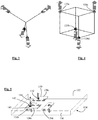
- the microphone array 10 comprises four microphones 120a, 120b, 120c, 120d placed at positions which correspond to the four non-adjacent corners of a cube of side length d, and therefore each equidistant from the other three.
- This geometry forms a tetrahedral microphone array.
- the acoustic particle velocity, v ( r , w , t ), instantaneous intensity, and direction of the intensity vector, ⁇ ( ⁇ , t ) can be obtained from p x , p y , and p w .
- the microphones 120a, 120b, 120c, 120d in the array are closely spaced, plane wave assumption can safely be made for incident waves and their directions can be calculated. If simultaneously active sound signals do not overlap directionally in short time-frequency windows, the directions of the intensity vectors correspond to those of the sound sources randomly shifted by major reflections.
- the B-format signals, and the calculations described above are based on the instantaneous difference in pressure between respective pairs of the microphones, and therefore the measured instantaneous pressure gradients in the respective directions between those pairs of microphones.
- Spatial filtering involves, for each possible source direction or 'look direction' multiplying each frequency component by a factor which varies (as defined by the filter) with the difference between the look direction and the direction from which the frequency component is detected as coming.
- the elements of this vector can be considered as the proportion of the frequency component that is detected as coming from each of the N possibe source directions.
- This method implies block-based processing, such as with the overlap-add technique.
- the recorded signals are windowed, ie divided into time periods or windows of equal length, and converted into frequency domain after which each sample is processed as in (9). These are then converted back into time-domain, windowed with a matching window function, overlapped and added to remove block effects.
- the pressure gradient along the z axis, p Z ( ⁇ , t ) can also be calculated and used for estimating both the horizontal and the vertical directions of the intensity vectors.
- the directivity function is obtained by using this function, which then enables spatial filtering considering both the horizontal and vertical intensity vector directions.
- sound received from one or more chosen directions can be selected and, for example, reproduced through the speaker system 14.
- each microphone has a sensing surface, generally being the surface of a diaphragm, which may be flat, and may be circular or square in shape, and therefore has a geometrical centre. This forms the centre point of the sensor, which is the point at which it is nominally measuring the pressure. A line from that centre point and perpendicular to the sensing surface can be considered as the central axis of the microphone and extends in the direction in which the microphone is facing.
- the microphones are arranged such that each of them faces away from a common central point which is the centre of the tetrahedron.
- the four microphones 120a, 120b, 120c, 120d of the array are arranged in two pairs.
- the two microphones making up the pair are arranged in the same orientation as each other, so that they both face in the same direction, as indicated by the arrows in Figure 4 , which is perpendicular to an imaginary line between their two centre points.
- the two pairs of microphones face in opposite directions, each pair facing generally away from the other pair.
- the positions of the microphones 120a, 120b, 120c, 120d in the array relative to each other is the same as in a tetrahedral array, with the centre point of each microphone being the same distance from the centre points of each of the other three.
- the microphone array 120 is constructed as a planar support member 130 having two opposite support surfaces 132, 134 on opposite sides. As the support member 130 is flat and regular, the two surfaces 132, 134 are parallel to each other. One pair of microphones 120a, 120c is mounted on one of the surfaces 132 and the other pair of microphones 120b, 120d is mounted on the other of the surfaces 134.
- Each of the microphones 120a, 120b, 120c, 120d is a MEMS microphone and comprises a body 140 with a diaphragm 142 formed on it. The body has a rear surface which is adhered directly to the support member 130 and a front surface in which the diaphragm 142 is formed.
- the diaphragm 142 is circular and so has a centre point 143 at its geometrical centre as described above.
- the diaphragm also has rotational symmetry about a central axis 144 which extends through the centre point and perpendicular to the plane of the diaphragm.
- the central axis extends in the direction in which the microphone faces.
- the first pair of microphones 120a, 120c are mounted so that they both face in the same direction which is perpendicular to the plane of the support member 130, and the second pair of microphones 120b, 120d are mounted so that they face in the opposite direction.
- the spacing between the diaphragm centres of the two microphones in the first pair is the same as the spacing between the diaphragm centres of the two microphones in the second pair, and is selected so that each of the microphone centre points is equidistant from the other three.
- a barrier 150 is provided between the two sensors 120c, 120d on one side of the support member 130, and a further barrier 152 is provided between the two sensors 120a, 120c on the other side of the support member 130.
- Each of the barriers is located symmetrically between the two sensors 120a, 120b, or 120c, 120d that it is located between.
- the barriers 150, 152 are substantially flat and planar and therefore perpendicular to each other, and both perpendicular to the support member 130.
- the sensors are not shown with significant height in Figure 6
- the centres of the sensors 120c, 120d are a certain height above the surface of the support member 130.
- the barriers 150, 152 extend upwards from the support member 130 to a height that is above the centres of the sensors 120c, 120d, or 120a, 120b.
- the barrier 150 is orientated so as not to be perpendicular to the line between the two centre points of the sensors 120a, 120c that it separates.
- each of the barriers 150, 152 of Figure 6 is replaced by a pair of barriers 160, 162.
- the two barriers 160, 162 on each side are parallel to each other, but in offset planes, and perpendicular to the two barriers on the other side of the support member.
- one or both of the barriers 160 and 162 may be constructed from electronic components, for example capacitors such as electrolytic capacitors.
- DC-blocking capacitors are required to couple electronic signals from MEMS or electret microphone capsules and advantageously should be located close to the drive voltage pin (Vdd) of the capsule. This makes use of deliberately locating the capacitors around the microphone capsule as shown in Figure 8 , or in a different location, to form the barrier producing the acoustic effect described above.
- the flat barrier 150 of Figure 7 is replaced by a barrier 170 having two mutually perpendicular surfaces 170a, 170b facing each of the sensors 174a, 174c.
- the surfaces 170a, 170b are again all perpendicular to the surfaces of the support member on which sensors 174a, 174c are mounted. Therefore each sensor 174a, 174c is located in a cavity defined by three mutually perpendicular surfaces.
- a mobile phone 200 includes a sound reception system comprising a processor (not shown) on the phone, a deformable button 201, and a microphone array comprising four microphones 202a, 202b mounted on a support member 204, as described above with reference to Figure 5 , and as shown in more detail in Figures 11 , 12a and 12b .
- the phone also comprises a casing or housing 206, having front and rear walls 208, 210 which are parallel to each other, and parallel to the support member 204, which is in the form of a printed circuit board (PCB) with the microphones 202a, 202b, the processor not shown, and other electronic components mounted on it.
- PCB printed circuit board
- the microphone array 202 is located within the housing 206 between the front and rear walls 208, 210, with the push button 201 extending over it and a bezel 203 around it.
- the barriers 212, 214 in this case are formed as part of the housing 206, and project inwards from the front and rear walls 208, 210 respectively with their inner ends contacting the support member 204.
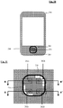
- Each the front and rear walls has two apertures 216, 217, 218, 219 through it, one on each side of the barrier 212, 214.
- the apertures 216, 218 in the front wall 208 each have side walls that are perpendicular to the parallel surfaces of the front wall 208, and are in the form of elongate curved slots that form diagonally opposite quarters of a rounded square.
- the two apertures 217, 219 in the rear wall 210 are the same size and shape, and located so that, viewed from the front as in Figure 11 , they form the remaining two quarters of the same rounded square.
- Each of the apertures is closest to a respective one of the microphones 202a, 202b, 202c, 202d, and the apertures are each the same distance from the respective microphones.
- the exact shape and location of the apertures can vary, and the depth of the air gap between each microphone and its respective opening, to attain the necessary microphone directivity of each microphone and thereby overall microphone array performance.
- the fact that the four apertures are the same shape as each other and symmetrically arranged with respect to the microphone array helps to improve the performance of the system.
- the centre point 220 of the microphone array is located in the middle of the support member 204 and in the centre plane of the barriers 212, 214.
- passing through the aperture only requires that, for each aperture, the line passes through the volume bounded by the side walls of the aperture and the planes of the parallel surfaces of the wall 208, 210 of the housing.
- each of the microphones 202a, 202b, 202c, 202d is shown in Figures 12a and 12b as the dotted lines 230a, 230b, 230c, 230d.
- the distance of the line in any direction from the sensing centre point of the sensor 223a, 223b, 223c, 223d indicates the sensitivity of the microphone in that direction, resulting from the support and the barrier and other objects present.
- the sensitivity in a direction here is the inverse of the attenuation of sound coming from that direction.
- the attenuation in the ('preferred') direction away from the array centre point, in this case through the aperture 216, 217, 218, 219, is significantly less that the attenuation in the perpendicular direction. It is preferable for the attenuation to be at least 1dB lower in the preferred direction than in any perpendicular direction, and more preferable for it to be at least 2dB lower, or even 3dB lower.
- the basic arrangement of the system is as shown in Figures 12a and 12b , but the shape of the apertures is different.
- the apertures are a simple oval shape, and offset slightly from the equivalent of lines 222 and 224.
- the apertures are again of a simple oval shape, but again located on the equivalents of the lines 222, 224.
- the apertures are rectangular and, though located on the equivalent of the lines 222, 224, are not orientated so as to be aligned with them.
- the apertures are of various different shapes and all orientated so as to be aligned with the equivalent of the lines 222, 224.
- a microphone array forming part of a system of a further embodiment of the invention comprises four microphones 520a, 520b, 520c, 520d, again spaced so that the centre point of each of them is equidistant from the centre points of the three others.
- a group of three of the microphones 520a, 520b, 520c all face in the same direction, and the one remaining microphone 520d faces in the opposite direction.
- the group of three microphones 520a, 520b, 520c lie in a common plane, and the direction in which they face is perpendicular to that plane, and generally away from the other, fourth, microphone 520d.
- the fourth microphone 520d faces away from the common plane of the other three 520a, 520b, 520c.
- the array of Figure 14 is constructed in a similar manner to that of Figure 5 , except that three of the microphones 520a, 520b, 520c are mounted on one surface of the support member 530, and the other microphone 520d is mounted on the opposite surface of the support member 530.
- the array is mounted on a phone housing 540 having front and rear walls 542, 544, and an aperture 546a, 546b, 546c, 546d is provided in the housing 540 for each microphone.
- each of the apertures is closest to, and aligned with, a respective on of the microphones.
- each of these three barriers is arranged perpendicular to the line between the sensing centre points of the two microphones that it separates, and equidistant from those two centre points.
- FIG 17 which shows a side projection of an array similar to that of Figures 12a and 12b
- the four microphones 620a, 620b, 620c, 620d are mounted on opposite sides of the support member 630, and the two microphones on each side of the support member are separated by a barrier 650, and apertures 646a, 646b, 646c, 646d are provided in the housing, one for each microphone.
- the dotted lines show the directionality of the microphones.
- the barriers 750 are formed by a solid block of material in which the microphones 720a, 720b, 720c, 720d are embedded, and the apertures are formed as channels 746a, 746b, 746c, 746d formed within the block of material.
- the channels are of equal length to each other, and each extend, from the microphone centre point, along the line equivalent to the lines 222, 224 through the array centre point.
- Figure 19 is similar to that of Figure 17 , but the walls of the phone housing to not extend over the array of microphones 820a, 820b, 820c, 820d, so there are not separate apertures for each of the microphones. However, the barriers 850 are present to provide the symmetry of response.
- the microphones 920a, 920b, 920c, 920d are again embedded in a block of material which forms the barriers 50, and in this case there are two channels extending outwards through the block form each microphone centre point, one 946a in the direction in which the microphone is facing, and one 946b perpendicular to that.
- a substrate 1030 has two opposite parallel surfaces, with two microphones 1020a, 1020b mounted on one and two further microphones 1020c, 1020d mounted on the other.
- a first barrier 1050 is provided between the first two microphones 1020a, 1020b, and a second barrier 1052 is provided between the second two microphones 1020c, 1020d.
- the two barriers are parallel to each other.
- the barriers 1052, 1054 are arranged so that, for any given frequency of sound, they have the same attenuation effect as the substrate 1030.
- the substrate 1130 has two opposite parallel surfaces, with two microphones 1120a, 1120b mounted on one and two further microphones 1120c, 1120d mounted on the other.
- the distance between the two microphones 1120a, 1120b on one side of the substrate is the same as the distance between the two microphones 1120c, 1120d on the other side, and when seen in front view, i.e. looking perpendicular to the plane of the substrate, as in Figure 23a , the four microphones are seen to form a square.
- the four microphones are therefore at four non-adjacent corners of a rectangular cuboid with two square faces parallel to the surfaces of the substrate 130.
- the spacing L 31 between the microphones in the direction perpendicular to the plane of the substrate, which is the length of the shortest sides of the rectangular cuboid, is less than the shortest spacing L 21 between the microphones in two directions parallel to the plane of the substrate, which is the length of the longer sides of the rectangular cuboid.
- the substrate is a truly planar sheet material
- directions perpendicular to, and parallel to, the plane of the substrate will be clearly defined.
- that plane can be considered to be a geometrical plane 1121 which is parallel to the line between the sensing centre points of the two sensors 1120a, 1120b on one side of the substrate, and parallel to the line between the sensing centre points of the two sensors 1120c, 1120d on the opposite side of the substrate, and equidistant from those two lines.
- p2/p1 trans is the ratio of the pressures at microphones on the same side of the substrate when the sound is travelling transverse to, or parallel to, the surface of the substrate
- p3/p1 perp is the ratio of the pressures at microphones on opposite sides of the substrate when the sound is travelling perpendicular to the surface of the substrate
- the microphone spacing of that embodiment is well suited to use in a mobile telecommunications device.
- Such devices are usually relatively thin, having two large parallel surfaces forming the front and back of the device with a screen on the front surface.
- the microphone array of Figures 23a and 23b can be housed within such a telecommunications device with the substrate parallel to, and between, the front and back surfaces, so that two of the microphones 1120a, 1120b are under the front surface, between the front surface and the substrate, and the other two microphones 1120c, 1120d are under the rear surface, between the rear surface and the substrate.
- the substrate, or support member can comprise the PCB carrying the other electronic components of the device.
- the spacing between the front two microphones 1120a, 1120b can be at least 100% greater than the spacing between the front and rear
- the systems described above are arranged for source separation, i.e. to identify the components of a sound mixture coming from each of a plurality of sources in different locations.
- the systems can be arranged to identify components of sound from just a single direction. This can be useful in directional listening devices.
Landscapes
- Engineering & Computer Science (AREA)
- Signal Processing (AREA)
- Physics & Mathematics (AREA)
- Acoustics & Sound (AREA)
- Health & Medical Sciences (AREA)
- Otolaryngology (AREA)
- Multimedia (AREA)
- Circuit For Audible Band Transducer (AREA)
- Obtaining Desirable Characteristics In Audible-Bandwidth Transducers (AREA)
Description
- The present invention relates to systems for the separation of a mixture of sounds from different sound sources, and in particular to the design of microphone arrays in such systems.
- The separation of convolutive mixtures aims to estimate the individual sound signals in the presence of other such signals in reverberant environments. As sound mixtures are almost always convolutive in enclosures, their separation is a useful pre-processing stage for speech recognition and speaker identification problems. Other direct application areas also exist such as in hearing aids, teleconferencing, multichannel audio and acoustical surveillance.
- Our earlier patent application published as
WO 2009/050487 discoses a system for separating a mixture of acoustic signals from a plurality of sources which comprises a sensor array comprising a plurality of pressure sensors and a processor arranged to receive signals from the sensors, and derive from them a series of sample values of directional pressure gradient, identify a plurality of frequency components of the signals, and define an associated direction for each frequency component. The system is then arranged to identify a subset of the frequency components with a source, thereby to define an accoustic signal for that source. Signals for several sources can be defined. In order to provide three dimensional source separation, a three dimensional array of sensors can be used, for example a tetrahedral array. - Our further earlier patent application no
PCT/GB2013/050784 WO2009/050487 , but in which the array is designed for ease of manufacture. This is achieved by forming the array of support means having two opposite sides and four sensors, with at least one of the sensors supported on each side of the support means, and the sensors facing in directions that are parallel to each other. Because the systems described inWO2009/050487 andPCT/GB2013/050784 WO2009/050487 andPCT/GB2013/050784 US2012/0051548 discloses a mobile phone having a primary microphone and at least one secondary microphone for determining the direction of a sound source.US 7 058 184 discloses an echolocation device having a tetrahedra array of microphones. - The formation of acoustic pressure gradients, and thereby ability of the algorithm of
PCT/GB2013/050784 - Accordingly the present invention provides a system for directionally selective sound reception comprising an array of four pressure sensors each arranged to output a pressure signal indicative of pressure, and processing means arranged to receive the pressure signals, the sensor array comprising support means supporting the four sensors, a first one and a second one of the sensors being mounted on a first surface on one side of the support means and facing in a first direction and at least a third sensor being supported on a second surface, opposite to the first surface and on an opposite side of the support means and facing in a second direction opposite to the first direction, wherein the sound pressure difference measured between the first sensor to the second sensor caused by sound arriving at the array from a direction parallel to the first and second surfaces of the support means is dependent on the distance between the first and second sensors and the nature of material in the space between the first and second sensors, and the sound pressure difference measured between the first and third sensors caused by sound travelling perpendicular to the first and second surfaces of the support means is dependent on the distance between the first and third sensors and the nature of material in the space between the first and third sensors, charcterised in that the spacings and the materials are selected such that the sound pressure differences are substantially equal, or one of the sound pressure differences is higher than the other, but by no more than 10%, and in that the spacing between the first and second sensors is greater than the distance between the first and third sensors, or a barrier is provided between the first and second sensors.
- The spacing of the sensors, and the materials located between the sensors may be selected so that the error in the measured direction of the sound component is no more than 45°, preferably no more than 30°. This may be for sound coming from any direction over a 360° range, or it may be for sound coming from any direction in three dimensions.
- For example the spacing between the first and second sensors may be at least 10%, or at least 25% , or at least 50%, or at least 100% greater than that between the first and third sensors.
- As the sound pressure differences are frequency dependent, the sound pressure differences may be those at at least one audible frequency. The audible frequency range is from 20Hz to 20kHz. For example frequency may be 1000Hz, or 256Hz. Substantially equal may be that one of the sound pressure differences is no more than 50%, or no more than 25%, or no more than 10%, or no more than 5% higher than the other.
- The attenuations, or pressure differences, may be achieved by having both one or more barriers and greater spacing.
- The spacing and/or the barrier or barriers may therefore be arranged at least partially to compensate for the directional asymmetry produced by the presence of the support means.
- The processing mean may be arranged to derive from the pressure signals a series of sample values of directional pressure gradient. The processing means may be arranged to identify a plurality of frequency components of the signals, and define an associated direction for each frequency component.
- The processing means may be arranged to identify a plurality of frequency components of the signals, identify at least one source direction, and identify at least one of the components as coming from the source direction.
- The barrier may be mounted on the support means. The support means may be planar. The barrier may be planar and/or may have two parallel sides. The barrier, or the sides of the barrier, may extend perpendicular to the plane, or the sides, of the support means.
- Two of the sensors may be supported on one of the sides of the support means and two of the sensors may be supported on the other of the sides. In this case there may be two barriers, each located between the two sensors on a respective side of the support means. The barrier, or each of the barriers, may have two perpendicular surfaces facing each of the two sensors that it is located between. These surfaces may each be perpendicular to the plane of the surface of the support on which the sensor is mounted. This can result in one of, or each of, the microphones being located in a cavity defined between three perpendicular surfaces.
- Alternatively one of the sensors may be supported on one of the sides and three of the sensors may be suported on the other of the sides. In this case the barrier may be located between at least two of said three sensors.
- the acoustic attentuation of sound travelling from the first sensor to the third sensor. Substantially equal may be that one of the attenuations is no more than 50%, or no more than 25%, or no more than 10%, or no more than 5% higher than the other.
- The attenuations, or pressure differences, may be achieved by having a greater spacing between the first and second sensors than the first and third sensors, in which case the material between the first and second sensors is typically air, or by providing a barrier between the first and third sensors, typically a solid barrier, which will generally have a higher density, and acoustic impedence, than air and hence provide more attenuation, or by both one or more barriers and greater spacing.
- The spacing and/or the barrier or barriers may therefore be arranged at least partially to compensate for the directional asymmetry produced by the presence of the support means.
- The system may comprise processing means arranged to receive presssure signals from each of the sensors.
- The present invention further provides a system for directionally selective sound reception comprising an array of pressure sensors each arranged to output a pressure signal indicative of pressure, and processing means arranged to receive the pressure signals, the sensor array comprising support means having two opposite sides and four sensors, at least two of sensors being supported on one side of the support means, and a barrier located between said two of the sensors.
- The present invention also provides a system for directionally selective sound reception comprising an array of pressure sensors each arranged to output a pressure signal indicative of pressure, and processing means arranged to receive the pressure signals, the sensor array comprising support means supporting the four sensors, at least two of sensors being arranged to face in one direction, the system including a barrier located between said two of the sensors. The barrier may comprise part of the support means, or may be a separate component.
- In each case, the processing mean may be arranged to derive from the pressure signals a series of sample values of directional pressure gradient. The processing means may be arranged to identify a plurality of frequency components of the signals, and define an associated direction for each frequency component.
- The processing means may be arranged to identify a plurality of frequency components of the signals, identify at least one source direction, and identify at least one of the components as coming from the source direction.
- The barrier may be mounted on the support means. The support means may be planar. The barrier may be planar and/or may have two parallel sides. The barrier, or the sides of the barrier, may extend perpendicular to the plane, or the sides, of the support means.
- Two of the sensors may be supported on one of the sides of the support means and two of the sensors may be supported on the other of the sides. In this case there may be two barriers, each located between the two sensors on a respective side of the support means. The barrier, or each of the barriers, may have two perpendicular surfaces facing each of the two sensors that it is located between. These surfaces may each be perpendicular to the plane of the surface of the support on which the sensor is mounted. This can result in one of, or each of, the microphones being located in a cavity defined between three perpendicular surfaces.
- Alternatively one of the sensors may be supported on one of the sides and three of the sensors may be suported on the other of the sides. In this case the barrier may be located between at least two of said three sensors.
- Each of the sensors may have a sensing centre point. This may be the point at which the sensor nominally measures the pressure. It may be the centre of a region over which the sensor is arranged to sense pressure. For example it may be the centre of a diaphragm of the sensor. The sensing centre points of the four sensors may be arranged such that each of them is equidistant from each of the other three. The sensing centre points may be arranged so that they lie at the corners of a regular tetrahedron.
- The height of the barrier above the surface of the support needs to be sufficient to have an appreciable effect. For example a part of the barrier may be located on a straight line between the sensing centre points of two of the sensors. This may be the case even if the barrier is not mounted on the support means. For example the system may include a housing in which the array is housed. The barrier may be mounted on the housing. There may be a gap between the barrier and the support means.
- Regardless of where the barrier is mounted, the housing may have one or more apertures though it each associated with at least one of the sensors. Preferably there are four apertures, one associated with each of the sensors. The apertures may be of any shape, and may be all of the same shape, or may be of different shapes. The apertures may be spaced apart by a greater distance than the sensing centre points of the sensors. Where the sensors, or the sensing centre points of the sensors, are each equidistant from the other three, and therefore also equidistant from a centre point, the apertures may be arranged so that each of them lies on a line from the centre point extending outwards through the sensor, or the sensing centre point. The apertures may also each be equidistant from the other three.
- The attenuation of sounds in the direction away from the array centre point, the 'preferred' direction, is preferably at least 1dB lower in the preferred direction than in any perpendicular direction, and more preferable for it to be at least 2dB lower, or even 3dB lower. This is preferably for all sounds in the acoustic range, but may be just at one frequency, for example 250Hz.
- The system may be arranged to separate a mixture of acoustic signals from a plurality of sources, or it may be a directional listening system arranged to receive sounds only from one or more selected directions.
- Each of the sensors may have a central axis. The central axis may be an axis about which the sensor has at least a degree of rotational symmetry. The central axis may be a line through the centre of the sensor, and may extend in a direction in which the sensor faces. The sensor may have a rear side which is closest to the support means and a front side, opposite the rear side, which faces in said direction. The two, or three, sensors on one side of the support means may be parallel to each other. For example their central axes may be parallel to each other, or they may face in the same direction. Where there are two sensors on each of the surfaces, the two sensors on the other side of the support means may also be parallel to each other.
- The processing means may be arranged to define a series of time windows; and for each time window:
- a) generate from the pressure signals a series of sample values of measured directional pressure gradient;
- b) identify different frequency components of the pressure signals;
- c) for each frequency component define an associated direction;
- d) from the frequency components and their associated directions generate a separated signal for one of the sources.
- The processing means may be arrange to define from the pressure signals a series of values of a pressure function. A directionality function may be applied to the pressure function to generate the separated signal for the source. For example, the pressure function may be, or be derived from, one or more of the pressure signals, which may be generated from one or more omnidirectional pressure sensors, or the pressure function may be, or be derived from, one or more pressure gradients.
- The separated signal may be an electrical signal. The separated signal may define an associated acoustic signal. The separated signal may be used to generate a corresponding acoustic signal.
- The associated direction may be determined from the pressure gradient sample values.
- The directions of the frequency components may be combined to form a probability distribution from which the directionality function is obtained.
- The directionality function may be obtained by modelling the probability distribution so as to include a set of source components each comprising a probability distribution from a single source.
- The probability distribution may be modelled so as also to include a uniform density component.
- The source components may be estimated numerically from the measured intensity vector direction distribution.
- Each of the source components may have a beamwidth and a direction, each of which may be selected from a set of discrete possible values.
- The directionality function may define a weighting factor which varies as a function of direction, and which is applied to each frequency component of the omnidirectional pressure signal depending on the direction associated with that frequency.
- The system may further comprise, in any combination, any one or more features of the preferred embodiments of the invention which will now be described by way of example only with reference to the accompanying drawings.
-
-
Figure 1 is a schematic diagram of a system according to an embodiment of the invention; -
Figure 2 is a diagram of a microphone array forming part of the system ofFigure 1 ; -
Figure 3 is a scematic diagram of the orientation of microphones in a known microphone array; -
Figure 4 is a schematic diagram of the orientation of the microphones in the array ofFigure 2 ; -
Figure 5 is a perspective view of the microphone array ofFigures 2 and4 ; -
Figure 6 is a diagram of the array ofFigure 5 showing barriers which are not shown inFigure 5 ; -
Figure 7 is a diagram of a microphone array according to a second embodiment of the invention; -
Figure 8 is a diagram of a microphone array according to a third embodiment of the invention; -
Figure 9 is a diagram of a microphone array according to a fourth embodiment of the invention; -
Figure 10 is a front view of a phone unit including a microphone array according to a fifth embodiment of the invention; -
Figure 10a is a rear view of the phone ofFigure 10 ; -
Figure 11 is an enlargement of part ofFigure 10 ; -
Figure 11a is an enlargement of part ofFigure 10a ; -
Figures 12a and 12b are sections on lines A-A and B-B ofFigure 11 ; -
Figures 13a, 13b, 13c, 13d, 13e, 13f show modifications to the embodiment ofFigure 10 with different shaped apertures in the phone casing; -
Figure 14 is a schematic view of a microphone array according to a further embodiment of the invention; -
Figure 15 is a schematic side view the array ofFigure 14 ; -
Figure 16 is a sechematic plan view of the array ofFigure 14 ; -
Figure 17 is a section through an array according to a further embodiment of the invention; -
Figure 18 is a section through an array according to a further embodiment of the invention; -
Figure 19 is a section through an array according to a further embodiment of the invention; -
Figure 20 is a section through an array according to a further embodiment of the invention; -
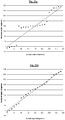
Figures 21a and 21b are plots showing the deduced direction (angle) of the source as a function of actual angle for a system without barriers and the same system with barriers; -
Figure 22a is a schematic front view of a micorphone array corresponding to that ofFigure 6 ; -
Figure 22b is a schematic plan view of the microphone array ofFigure 22a ; -
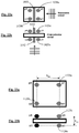
Figure 23a is a schemaitc front view of a microphone array accordin to a further embodiment of the invention; and -
Figure 23b is a schematic plan view of the microphone array ofFigure 23a . - Referring to
Figure 1 , an audio source separation system according to a first embodiment of the invention comprises amicrophone array 10, a processing system, in this case apersonal computer 12, arranged to receive audio signals from the microphone array and process them, and aspeaker system 14 arranged to generate sounds based on the processed audio signals. Themicrophone array 10 is located at the centre of a circle of 36 nominal source positions 16. Sound sources 18 can be placed at any of these positions and the system is arranged to separate the sounds from each of the source positions 16. Clearly in a practical system the sound source positions could be spaced apart in a variety of ways. - Referring to
Figure 2 , themicrophone array 10 comprises fourmicrophones - Let us consider a plane wave arriving from the direction γ(ω,t) on the horizontal plane with respect to the center of the cube. If the pressure at the centre due to this plane wave is po (ω, t), then the pressure signals pa, pb, pc, pd recorded by the four
microphones 


- If, kd << 1, ie when the microphones are positioned close to each other in comparison to the wavelength, it can be shown by using the relations cos(kd cosγ) ≈ 1, cos(kd sin γ) ≈ 1, sin (kd cos γ) ≈ kd cosγ and sin (kd sin γ) ≈ kd sin γ that,



- The acoustic particle velocity, v(r,w,t), instantaneous intensity, and direction of the intensity vector, γ(ω,t) can be obtained from px, py, and pw.
- Since the
microphones - It will be appreciated that the B-format signals, and the calculations described above, are based on the instantaneous difference in pressure between respective pairs of the microphones, and therefore the measured instantaneous pressure gradients in the respective directions between those pairs of microphones.
- The exhaustive separation of the sources by decomposing the sound field into plane waves using intensity vector directions will now be described. This essentially comprises taking N possible directions, and identifying from which of those possible directions the sound is coming, which indicates the likely positions of the sources.
- In a short time-frequency window, the pressure signal pw (ω, t) can be written as the sum of pressure waves arriving from all directions, independent of the number of sound sources. Then, a crude approximation of the plane wave s(µ,ω,t) arriving from direction µ can be obtained by spatial filtering pW (ω,t) as,

- Spatial filtering involves, for each possible source direction or 'look direction' multiplying each frequency component by a factor which varies (as defined by the filter) with the difference between the look direction and the direction from which the frequency component is detected as coming.
- For exhaustive separation, ie separation of the mixture between a total set of N possible source directions, N directional filters are used with look directions µ varied by 2π/N intervals. Then, the spatial filtering yields a row vector s̃ of size N for each time-frequency component:

- The elements of this vector can be considered as the proportion of the frequency component that is detected as coming from each of the N possibe source directions.
- This method implies block-based processing, such as with the overlap-add technique. The recorded signals are windowed, ie divided into time periods or windows of equal length, and converted into frequency domain after which each sample is processed as in (9). These are then converted back into time-domain, windowed with a matching window function, overlapped and added to remove block effects.
- Due to the 3D symmetry of the tetrahedral microphone array of
Figure 2 , the pressure gradient along the z axis, pZ (ω,t) can also be calculated and used for estimating both the horizontal and the vertical directions of the intensity vectors. - The active intensity in 3D can be written as:

- Then, the horizontal and vertical directions of the intensity vector, µ(ω,t) and v (ω,t), respectively, can be obtained by


- The extension of the von Mises distribution to 3D case yields a Fisher distribution which is defined as

- For separation of sources in 3D, the directivity function is obtained by using this function, which then enables spatial filtering considering both the horizontal and vertical intensity vector directions.
- Once the spatial filtering has been performed, sound received from one or more chosen directions can be selected and, for example, reproduced through the
speaker system 14. - Even though the microphones of the array are of the type which is referred to as omnidirectional, they are generally constructed in a way such that they can be considered to face in a particular direction. Typically each microphone has a sensing surface, generally being the surface of a diaphragm, which may be flat, and may be circular or square in shape, and therefore has a geometrical centre. This forms the centre point of the sensor, which is the point at which it is nominally measuring the pressure. A line from that centre point and perpendicular to the sensing surface can be considered as the central axis of the microphone and extends in the direction in which the microphone is facing. Referring to
Figure 3 , in a known tetrahedral microphone array, the microphones are arranged such that each of them faces away from a common central point which is the centre of the tetrahedron. However, referring toFigure 4 , in this embodiment the fourmicrophones Figure 4 , which is perpendicular to an imaginary line between their two centre points. The two pairs of microphones face in opposite directions, each pair facing generally away from the other pair. The positions of themicrophones - Referring to
Figure 5 , the microphone array 120 is constructed as aplanar support member 130 having two opposite support surfaces 132, 134 on opposite sides. As thesupport member 130 is flat and regular, the twosurfaces microphones surfaces 132 and the other pair ofmicrophones surfaces 134. Each of themicrophones body 140 with adiaphragm 142 formed on it. The body has a rear surface which is adhered directly to thesupport member 130 and a front surface in which thediaphragm 142 is formed. Thediaphragm 142 is circular and so has acentre point 143 at its geometrical centre as described above. The diaphragm also has rotational symmetry about acentral axis 144 which extends through the centre point and perpendicular to the plane of the diaphragm. The central axis extends in the direction in which the microphone faces. The first pair ofmicrophones support member 130, and the second pair ofmicrophones - Referring to
Figure 6 , abarrier 150 is provided between the twosensors support member 130, and afurther barrier 152 is provided between the twosensors support member 130. Each of the barriers is located symmetrically between the twosensors barriers support member 130. Although the sensors are not shown with significant height inFigure 6 , the centres of thesensors support member 130. Thebarriers support member 130 to a height that is above the centres of thesensors - Referring to
Figure 7 , in a further embodiment, thebarrier 150 is orientated so as not to be perpendicular to the line between the two centre points of thesensors - Referring to
Figure 8 , in a further embodiment, each of thebarriers Figure 6 is replaced by a pair ofbarriers barriers gap 163 between each pair of barriers, but this does not leave open a straight line path between the centre points of the twosensors 164a, 164c that they separate. - In one implementation, one or both of the
barriers Figure 8 , or in a different location, to form the barrier producing the acoustic effect described above. - Referring to
Figure 9 , in a further embodiment theflat barrier 150 ofFigure 7 is replaced by abarrier 170 having two mutuallyperpendicular surfaces sensors surfaces sensors sensor - Referring to
Figures 10 and 11 , in a further embodiment of the invention, amobile phone 200 includes a sound reception system comprising a processor (not shown) on the phone, adeformable button 201, and a microphone array comprising fourmicrophones support member 204, as described above with reference toFigure 5 , and as shown in more detail inFigures 11 ,12a and 12b . The phone also comprises a casing orhousing 206, having front andrear walls support member 204, which is in the form of a printed circuit board (PCB) with themicrophones microphone array 202 is located within thehousing 206 between the front andrear walls push button 201 extending over it and abezel 203 around it. Thebarriers housing 206, and project inwards from the front andrear walls support member 204. Each the front and rear walls has twoapertures barrier apertures front wall 208 each have side walls that are perpendicular to the parallel surfaces of thefront wall 208, and are in the form of elongate curved slots that form diagonally opposite quarters of a rounded square. As shown inFigure 11a , the twoapertures rear wall 210 are the same size and shape, and located so that, viewed from the front as inFigure 11 , they form the remaining two quarters of the same rounded square. Each of the apertures is closest to a respective one of themicrophones - As can be seen in
Figures 12a and 12b , thecentre point 220 of the microphone array, about which the four microphones are symmetrically arranged and from which they are equidistant, is located in the middle of thesupport member 204 and in the centre plane of thebarriers line 222, passing through that centre point, and through thecentre points microphones apertures line 224, passing through that centre point, and through the centre points 223b, 223c of two of the other twomicrophones apertures wall - The sensitivity of each of the
microphones Figures 12a and 12b as thedotted lines sensor aperture - Referring to
Figures 13a to 13f , in various other embodiments, the basic arrangement of the system is as shown inFigures 12a and 12b , but the shape of the apertures is different. In the embodiment ofFigure 13a , the apertures are a simple oval shape, and offset slightly from the equivalent oflines Figure 13b , the apertures are again of a simple oval shape, but again located on the equivalents of thelines Figure 13c , the apertures are rectangular and, though located on the equivalent of thelines Figures 13d, e and f , the apertures are of various different shapes and all orientated so as to be aligned with the equivalent of thelines - Referring to
Figure 14 , a microphone array forming part of a system of a further embodiment of the invention comprises fourmicrophones microphones microphone 520d faces in the opposite direction. The group of threemicrophones microphone 520d. Thefourth microphone 520d faces away from the common plane of the other three 520a, 520b, 520c. - Referring to
Figure 15 , the array ofFigure 14 is constructed in a similar manner to that ofFigure 5 , except that three of themicrophones support member 530, and theother microphone 520d is mounted on the opposite surface of thesupport member 530. The array is mounted on a phone housing 540 having front andrear walls aperture rear wall 544, each equidistant from the other two, and further apart than the microphones themselves, and one in thefront wall 542 directly above themicrophone 546d. Abarrier 550 is provided between each pair of adjacent microphones in the group of three that are on the rear side of the array. As can best be seen inFigure 16 , each of these three barriers is arranged perpendicular to the line between the sensing centre points of the two microphones that it separates, and equidistant from those two centre points. - Referring to
Figure 17 , which shows a side projection of an array similar to that ofFigures 12a and 12b , the fourmicrophones support member 630, and the two microphones on each side of the support member are separated by abarrier 650, andapertures - Referring to
Figure 18 , in a further embodiment, thebarriers 750 are formed by a solid block of material in which themicrophones channels lines - The embodiment of
Figure 19 is similar to that ofFigure 17 , but the walls of the phone housing to not extend over the array ofmicrophones - In the embodiment of
Figure 20 , as inFigure 18 , themicrophones barriers 50, and in this case there are two channels extending outwards through the block form each microphone centre point, one 946a in the direction in which the microphone is facing, and one 946b perpendicular to that. - The skilled man will of course appreciate that barriers in some arrangements might produce a Helmholtz cavity, with undesirable results. However the skilled man will equally be able to avoid this occurring in a practical system.
- While two barriers are shown in the examples describe, in some cases, where more limited directionality is required, one barrier may be sufficient.
- Referring to
Figures 21a and 21b , in an experiment a microphone array arranged as inFigure 8 was used, in a system as described with reference toFigure 1 , firstly without any barriers between the microphones, and then with thebarriers 161, 162 formed from plastic 4mm in height above the PCB. The results for the setup without the barriers are shown inFigure 21a , and it can be seen that the system was unable to distinguish clearly directions around 90° and 270°, ie close to the plane of the PCB. With the barriers inserted, the results were as shown inFigure 21b , and it can be seen that the ability of the system to accurately distinguish between sounds from angles around 90° and 270° is greatly improved. As can be seen, in this case the error in the measured angle, i.e. the angle between the measured direction and the true direction of the source, is nowhere more than 30 °. This - Referring to
Figures 22a and 22b , in a microphone array according to a further embodiment of the invention, a substrate 1030 has two opposite parallel surfaces, with twomicrophones further microphones 1020c, 1020d mounted on the other. Afirst barrier 1050 is provided between the first twomicrophones second barrier 1052 is provided between the second twomicrophones 1020c, 1020d. In this embodiment the two barriers are parallel to each other. As described above, and as is the case in the embodiments described above, thebarriers 1052, 1054 are arranged so that, for any given frequency of sound, they have the same attenuation effect as the substrate 1030. This means that, if the sound is travelling across the face of the substrate 1030, the pressure difference p1-p2 between the twomicrophones microphones Figure 22a and 22b respectively. - In the arrangement of
Figures 22a and 22b , it is the combination of equal spacing of the microphones and the equal attenuation of sound in the two perpendicular directions parallel and perpendicular to the plane of the substrate that makes the array respond in a symmetrical manner to sounds coming from all directions. However, rather than using a barrier to increase the attenuation in the direction parallel to the substrate, it is also possible to use the spacing of the microphones to achieve this. For example, referring toFigures 23a and 23b , in a further embodiment of the invention, the substrate 1130 has two opposite parallel surfaces, with twomicrophones 1120a, 1120b mounted on one and twofurther microphones 1120c, 1120d mounted on the other. In this case the distance between the twomicrophones 1120a, 1120b on one side of the substrate is the same as the distance between the twomicrophones 1120c, 1120d on the other side, and when seen in front view, i.e. looking perpendicular to the plane of the substrate, as inFigure 23a , the four microphones are seen to form a square. The four microphones are therefore at four non-adjacent corners of a rectangular cuboid with two square faces parallel to the surfaces of thesubstrate 130. The spacing L31 between the microphones in the direction perpendicular to the plane of the substrate, which is the length of the shortest sides of the rectangular cuboid, is less than the shortest spacing L21 between the microphones in two directions parallel to the plane of the substrate, which is the length of the longer sides of the rectangular cuboid. - Where the substrate is a truly planar sheet material, directions perpendicular to, and parallel to, the plane of the substrate will be clearly defined. For less regular support members, in order to clearly define the directions parallel to, and perpendicular to, the plane of the substrate, or support member, that plane can be considered to be a geometrical plane 1121 which is parallel to the line between the sensing centre points of the two
sensors 1120a, 1120b on one side of the substrate, and parallel to the line between the sensing centre points of the twosensors 1120c, 1120d on the opposite side of the substrate, and equidistant from those two lines. - For the purpose of explanation it can be assumed that the sound pressure varies with distance as it travels between two microphones m1 and m2 according to the formula:

- α is the natural rate of sound pressure decline in free space with no impediments;
- L21 is the physical separation between the two microphones m1 and m2 in the direction of the pressure wave travel;
- β21 is the pressure wave attenuation presented by the barrier placed between m1 and m2.
- This is an approximation which is valid over short distances.
- For the embodiments where the microphones are all equidistant from each other at the corners of a cube,


- Then to achieve p2/p1 = p3/p1, i.e. to get equal attenuation for both transverse and perpendicular sound directions, it is necessary to achieve β21 = β31. This can be achieved by matching the barrier to the substrate in the embodiments described above.
- However, the same effect can be achieved by varying L21 and L31 i.e. be altering the spacing of the microphones.
- In the case shown in
Figures 23a and 23b , L21 and L31 are chosen such that:
- Where p2/p1trans is the ratio of the pressures at microphones on the same side of the substrate when the sound is travelling transverse to, or parallel to, the surface of the substrate, and
p3/p1perp is the ratio of the pressures at microphones on opposite sides of the substrate when the sound is travelling perpendicular to the surface of the substrate, and therefore
- This means that the rotational symmetry of the response of the microphone array can be improved by physically separating the microphones such that the combined effect of the separation distance between them, and any physical barriers between them, is the same for sound travelling perpendicular and parallel to the plane of the substrate.
- Where no barriers are provided between the microphones on the same side of the substrate, and only the spacing of the microphones can be adjusted, the symmetry is achieved by making

- Referring to
Figures 23a and 23b , it will be appreciated that the microphone spacing of that embodiment is well suited to use in a mobile telecommunications device. Such devices are usually relatively thin, having two large parallel surfaces forming the front and back of the device with a screen on the front surface. The microphone array ofFigures 23a and 23b can be housed within such a telecommunications device with the substrate parallel to, and between, the front and back surfaces, so that two of themicrophones 1120a, 1120b are under the front surface, between the front surface and the substrate, and the other twomicrophones 1120c, 1120d are under the rear surface, between the rear surface and the substrate. As with the embodiments described above, the substrate, or support member, can comprise the PCB carrying the other electronic components of the device. In this arrangement the spacing between the front twomicrophones 1120a, 1120b can be at least 100% greater than the spacing between the front and rear - It will be appreciated that each of the different physical arrangements of sensors described above can be used with any of the processing methods described above with reference to equations (1) to (13).
- The systems described above are arranged for source separation, i.e. to identify the components of a sound mixture coming from each of a plurality of sources in different locations. However it will be appreciated that in other embodiments the systems can be arranged to identify components of sound from just a single direction. This can be useful in directional listening devices.
Claims (13)
- A system for directionally selective sound reception comprising an array of four pressure sensors (120a, 120b, 120c, 120d) each arranged to output a pressure signal indicative of pressure, and processing means arranged to receive the pressure signals, the sensor array comprising support means (130) supporting the four sensors, a first one (120a) and a second one (120c) of the sensors being mounted on a first surface (132) on one side of the support means and facing in a first direction and at least a third sensor (120b) being supported on a second surface (134), opposite to the first surface and on an opposite side of the support means and facing in a second direction opposite to the first direction, wherein the sound pressure difference measured between the first sensor to the second sensor caused by sound arriving at the array from a direction parallel to the first and second surfaces of the support means is dependent on the distance between the first and second sensors and the nature of material in the space between the first and second sensors, and the sound pressure difference measured between the first and third sensors caused by sound travelling perpendicular to the first and second surfaces of the support means is dependent on the distance between the first and third sensors and the nature of material in the space between the first and third sensors, characterised in that the spacings and the materials are selected such that the sound pressure differences are substantially equal, or one of the sound pressure differences is higher than the other, but by no more than 10 %, and in that the spacing between the first and second sensors is greater than the distance between the first and third sensors, or a barrier is provided between the first and second sensors.
- A system according to claim 1 wherein the sound pressure differences are those caused by sound at at least one audible frequency.
- A system according to claim 1 or claim 2 wherein the sound pressure differences are those produced by sounds at 1000Hz, or at 256Hz.
- A system according to any foregoing claim wherein one of the sound pressure differences is higher than the other, but by no more than 25 %.
- A system according to any foregoing claim wherein one of the sound pressure differences is higher than the other, but by no more than 5%.
- A system according to any foregoing claim wherein the support means is substantially planar.
- A system according to any preceding claim wherein the fourth one of the sensors is mounted on said opposite side of the support means.
- A system according to claim 7 wherein the spacing between the second and third sensors is the same as the spacing between the first and second sensors.
- A system according to any foregoing claim wherein each of the sensors has a sensing centre point, and the sensing centre points of the four sensors are arranged at the non-adjacent corners of an imaginary rectangular cuboid.
- A system according to claim 9 wherein each sensor comprises a diaphragm and the sensing centre is the geometrical centre of the diaphragm.
- A system according to any foregoing claim wherein the support means comprises a flat member with the two surfaces being on opposite sides of the member.
- A system according to claim 11 wherein the diaphragms of all four sensors are parallel to each other.
- A device having a front face and a rear face and including a system according to any foregoing claim, wherein each of the microphones faces perpendicular to one of the faces.
Applications Claiming Priority (3)
| Application Number | Priority Date | Filing Date | Title |
|---|---|---|---|
| GB201307694A GB201307694D0 (en) | 2013-04-29 | 2013-04-29 | Acoustic source separation |
| GB201315134A GB201315134D0 (en) | 2013-08-23 | 2013-08-23 | Acoustic source separation |
| PCT/GB2014/051325 WO2014177855A1 (en) | 2013-04-29 | 2014-04-29 | Microphone array for acoustic source separation |
Publications (2)
| Publication Number | Publication Date |
|---|---|
| EP2992687A1 EP2992687A1 (en) | 2016-03-09 |
| EP2992687B1 true EP2992687B1 (en) | 2018-06-06 |
Family
ID=50678224
Family Applications (1)
| Application Number | Title | Priority Date | Filing Date |
|---|---|---|---|
| EP14721931.5A Active EP2992687B1 (en) | 2013-04-29 | 2014-04-29 | Microphone array for acoustic source separation |
Country Status (4)
| Country | Link |
|---|---|
| US (1) | US9774953B2 (en) |
| EP (1) | EP2992687B1 (en) |
| KR (1) | KR102172718B1 (en) |
| WO (1) | WO2014177855A1 (en) |
Families Citing this family (33)
| Publication number | Priority date | Publication date | Assignee | Title |
|---|---|---|---|---|
| KR102049620B1 (en) * | 2012-03-26 | 2019-11-27 | 유니버시티 오브 서레이 | Directional Sound Receiving System |
| US9542603B2 (en) * | 2014-11-17 | 2017-01-10 | Polycom, Inc. | System and method for localizing a talker using audio and video information |
| US9565493B2 (en) | 2015-04-30 | 2017-02-07 | Shure Acquisition Holdings, Inc. | Array microphone system and method of assembling the same |
| US9554207B2 (en) | 2015-04-30 | 2017-01-24 | Shure Acquisition Holdings, Inc. | Offset cartridge microphones |
| US10334390B2 (en) | 2015-05-06 | 2019-06-25 | Idan BAKISH | Method and system for acoustic source enhancement using acoustic sensor array |
| US20170106789A1 (en) * | 2015-10-14 | 2017-04-20 | Catherine Holdbrook-Smith | Alert Assembly |
| JP6622594B2 (en) * | 2016-01-06 | 2019-12-18 | 株式会社オーディオテクニカ | Unidirectional microphone |
| US10367948B2 (en) | 2017-01-13 | 2019-07-30 | Shure Acquisition Holdings, Inc. | Post-mixing acoustic echo cancellation systems and methods |
| JP6878974B2 (en) * | 2017-03-16 | 2021-06-02 | 株式会社リコー | Imaging device, imaging system |
| US10609479B2 (en) * | 2017-09-14 | 2020-03-31 | Fujitsu Limited | Device and method for determining a sound source direction |
| EP3804356A1 (en) | 2018-06-01 | 2021-04-14 | Shure Acquisition Holdings, Inc. | Pattern-forming microphone array |
| US11297423B2 (en) | 2018-06-15 | 2022-04-05 | Shure Acquisition Holdings, Inc. | Endfire linear array microphone |
| US11310596B2 (en) | 2018-09-20 | 2022-04-19 | Shure Acquisition Holdings, Inc. | Adjustable lobe shape for array microphones |
| CN110351633B (en) * | 2018-12-27 | 2022-05-24 | 腾讯科技(深圳)有限公司 | Sound collection device |
| US11558693B2 (en) | 2019-03-21 | 2023-01-17 | Shure Acquisition Holdings, Inc. | Auto focus, auto focus within regions, and auto placement of beamformed microphone lobes with inhibition and voice activity detection functionality |
| EP3942842B1 (en) | 2019-03-21 | 2026-03-11 | Shure Acquisition Holdings, Inc. | Housings and associated design features for ceiling array microphones |
| TWI865506B (en) | 2019-03-21 | 2024-12-11 | 美商舒爾獲得控股公司 | Auto focus, auto focus within regions, and auto placement of beamformed microphone lobes with inhibition functionality |
| CN114051738B (en) | 2019-05-23 | 2024-10-01 | 舒尔获得控股公司 | Steerable speaker array, system and method thereof |
| CN114051637B (en) | 2019-05-31 | 2025-10-28 | 舒尔获得控股公司 | Low-latency automatic mixer with integrated voice and noise activity detection |
| WO2021041275A1 (en) | 2019-08-23 | 2021-03-04 | Shore Acquisition Holdings, Inc. | Two-dimensional microphone array with improved directivity |
| WO2021087377A1 (en) | 2019-11-01 | 2021-05-06 | Shure Acquisition Holdings, Inc. | Proximity microphone |
| US11552611B2 (en) | 2020-02-07 | 2023-01-10 | Shure Acquisition Holdings, Inc. | System and method for automatic adjustment of reference gain |
| USD944776S1 (en) | 2020-05-05 | 2022-03-01 | Shure Acquisition Holdings, Inc. | Audio device |
| WO2021243368A2 (en) | 2020-05-29 | 2021-12-02 | Shure Acquisition Holdings, Inc. | Transducer steering and configuration systems and methods using a local positioning system |
| WO2022091370A1 (en) * | 2020-10-30 | 2022-05-05 | Jfeアドバンテック株式会社 | Sound source azimuth locating device |
| JP7814400B2 (en) | 2021-01-28 | 2026-02-16 | シュアー アクイジッション ホールディングス インコーポレイテッド | Hybrid Audio Beamforming System |
| US11636842B2 (en) * | 2021-01-29 | 2023-04-25 | Iyo Inc. | Ear-mountable listening device having a microphone array disposed around a circuit board |
| US12452584B2 (en) | 2021-01-29 | 2025-10-21 | Shure Acquisition Holdings, Inc. | Scalable conferencing systems and methods |
| US12542123B2 (en) | 2021-08-31 | 2026-02-03 | Shure Acquisition Holdings, Inc. | Mask non-linear processor for acoustic echo cancellation |
| US12289584B2 (en) | 2021-10-04 | 2025-04-29 | Shure Acquisition Holdings, Inc. | Networked automixer systems and methods |
| US12525083B2 (en) | 2021-11-05 | 2026-01-13 | Shure Acquisition Holdings, Inc. | Distributed algorithm for automixing speech over wireless networks |
| US12250526B2 (en) | 2022-01-07 | 2025-03-11 | Shure Acquisition Holdings, Inc. | Audio beamforming with nulling control system and methods |
| US12598261B2 (en) | 2022-09-28 | 2026-04-07 | Shure Acquisition Holdings, Inc. | Wideband doubletalk detection for optimization of acoustic echo cancellation |
Family Cites Families (11)
| Publication number | Priority date | Publication date | Assignee | Title |
|---|---|---|---|---|
| CA1236607A (en) * | 1985-09-23 | 1988-05-10 | Northern Telecom Limited | Microphone arrangement |
| US7058184B1 (en) * | 2003-03-25 | 2006-06-06 | Robert Hickling | Acoustic measurement method and apparatus |
| US7054226B1 (en) | 2003-03-25 | 2006-05-30 | Robert Hickling | Method and apparatus for echolocation |
| US7936894B2 (en) * | 2004-12-23 | 2011-05-03 | Motorola Mobility, Inc. | Multielement microphone |
| WO2007084121A1 (en) | 2006-01-17 | 2007-07-26 | Robert Hickling | Sound source location and quantification using arrays of vector probes |
| GB0720473D0 (en) | 2007-10-19 | 2007-11-28 | Univ Surrey | Accoustic source separation |
| US8897455B2 (en) * | 2010-02-18 | 2014-11-25 | Qualcomm Incorporated | Microphone array subset selection for robust noise reduction |
| KR102049620B1 (en) | 2012-03-26 | 2019-11-27 | 유니버시티 오브 서레이 | Directional Sound Receiving System |
| US9354295B2 (en) | 2012-04-13 | 2016-05-31 | Qualcomm Incorporated | Systems, methods, and apparatus for estimating direction of arrival |
| US20130315402A1 (en) * | 2012-05-24 | 2013-11-28 | Qualcomm Incorporated | Three-dimensional sound compression and over-the-air transmission during a call |
| US9372111B2 (en) * | 2012-08-21 | 2016-06-21 | Board Of Regents, The University Of Texas System | Acoustic sensor |
-
2014
- 2014-04-29 US US14/787,621 patent/US9774953B2/en active Active
- 2014-04-29 WO PCT/GB2014/051325 patent/WO2014177855A1/en not_active Ceased
- 2014-04-29 EP EP14721931.5A patent/EP2992687B1/en active Active
- 2014-04-29 KR KR1020157033415A patent/KR102172718B1/en active Active
Non-Patent Citations (1)
| Title |
|---|
| None * |
Also Published As
| Publication number | Publication date |
|---|---|
| EP2992687A1 (en) | 2016-03-09 |
| KR20160003050A (en) | 2016-01-08 |
| US20160080867A1 (en) | 2016-03-17 |
| WO2014177855A1 (en) | 2014-11-06 |
| KR102172718B1 (en) | 2020-11-02 |
| US9774953B2 (en) | 2017-09-26 |
Similar Documents
| Publication | Publication Date | Title |
|---|---|---|
| US9774953B2 (en) | Microphone array for acoustic source separation | |
| US9473841B2 (en) | Acoustic source separation | |
| EP2208361B1 (en) | Microphone arrangement, having two pressure gradient transducers | |
| KR100595475B1 (en) | High Directivity Microphone Array | |
| EP0869697B1 (en) | A steerable and variable first-order differential microphone array | |
| EP2208360B1 (en) | Microphone arrangement comprising three pressure gradient transducers | |
| EP1867206B1 (en) | Microphone array and digital signal processing system | |
| CN107431866A (en) | Dual Diaphragm Microphone | |
| CN101981942B (en) | Microphone unit, near-talk voice input device and information processing system | |
| EP2604045A1 (en) | Active and passive directional acoustic radiating | |
| EP1986464A1 (en) | Highly directive endfire loudspeaker array | |
| Huang et al. | Combined differential beamforming with uniform linear microphone arrays | |
| Meyer | Microphone array for hearing aids taking into account the scattering of the head | |
| EP4510622A1 (en) | Acoustic output device | |
| CN121533035A (en) | Acoustic system with shared acoustic channels and shared sound ports | |
| EP3506650B1 (en) | Microphone array | |
| Ahn et al. | Interference structure-based directional acoustic-band amplifier for enhanced sound sensing | |
| Torio et al. | Unique directional properties of dual-diaphragm microphones | |
| US20250206600A1 (en) | Acoustic sensor devices with multiple sensing elements | |
| US12495244B2 (en) | Acoustic metamaterial device, method and computer program | |
| Lewis | Microphone array beamforming | |
| Gillett et al. | Performance benefits of spherical diffracting arrays versus free field arrays | |
| Elko et al. | Image‐derived second‐order differential microphones | |
| Shanechi et al. | Structural analysis of multisensor arrays for speech separation applications |
Legal Events
| Date | Code | Title | Description |
|---|---|---|---|
| PUAI | Public reference made under article 153(3) epc to a published international application that has entered the european phase |
Free format text: ORIGINAL CODE: 0009012 |
|
| 17P | Request for examination filed |
Effective date: 20151102 |
|
| AK | Designated contracting states |
Kind code of ref document: A1 Designated state(s): AL AT BE BG CH CY CZ DE DK EE ES FI FR GB GR HR HU IE IS IT LI LT LU LV MC MK MT NL NO PL PT RO RS SE SI SK SM TR |
|
| AX | Request for extension of the european patent |
Extension state: BA ME |
|
| DAX | Request for extension of the european patent (deleted) | ||
| STAA | Information on the status of an ep patent application or granted ep patent |
Free format text: STATUS: EXAMINATION IS IN PROGRESS |
|
| 17Q | First examination report despatched |
Effective date: 20170223 |
|
| GRAP | Despatch of communication of intention to grant a patent |
Free format text: ORIGINAL CODE: EPIDOSNIGR1 |
|
| STAA | Information on the status of an ep patent application or granted ep patent |
Free format text: STATUS: GRANT OF PATENT IS INTENDED |
|
| RIC1 | Information provided on ipc code assigned before grant |
Ipc: H04M 1/60 20060101ALN20171127BHEP Ipc: H04M 1/03 20060101ALI20171127BHEP Ipc: H04R 1/40 20060101AFI20171127BHEP Ipc: H04R 5/027 20060101ALI20171127BHEP Ipc: H04R 1/02 20060101ALN20171127BHEP |
|
| INTG | Intention to grant announced |
Effective date: 20171215 |
|
| GRAS | Grant fee paid |
Free format text: ORIGINAL CODE: EPIDOSNIGR3 |
|
| GRAA | (expected) grant |
Free format text: ORIGINAL CODE: 0009210 |
|
| STAA | Information on the status of an ep patent application or granted ep patent |
Free format text: STATUS: THE PATENT HAS BEEN GRANTED |
|
| AK | Designated contracting states |
Kind code of ref document: B1 Designated state(s): AL AT BE BG CH CY CZ DE DK EE ES FI FR GB GR HR HU IE IS IT LI LT LU LV MC MK MT NL NO PL PT RO RS SE SI SK SM TR |
|
| REG | Reference to a national code |
Ref country code: GB Ref legal event code: FG4D |
|
| REG | Reference to a national code |
Ref country code: CH Ref legal event code: EP Ref country code: AT Ref legal event code: REF Ref document number: 1007340 Country of ref document: AT Kind code of ref document: T Effective date: 20180615 |
|
| REG | Reference to a national code |
Ref country code: IE Ref legal event code: FG4D |
|
| REG | Reference to a national code |
Ref country code: DE Ref legal event code: R096 Ref document number: 602014026636 Country of ref document: DE |
|
| REG | Reference to a national code |
Ref country code: NL Ref legal event code: MP Effective date: 20180606 |
|
| REG | Reference to a national code |
Ref country code: LT Ref legal event code: MG4D |
|
| PG25 | Lapsed in a contracting state [announced via postgrant information from national office to epo] |
Ref country code: CY Free format text: LAPSE BECAUSE OF FAILURE TO SUBMIT A TRANSLATION OF THE DESCRIPTION OR TO PAY THE FEE WITHIN THE PRESCRIBED TIME-LIMIT Effective date: 20180606 Ref country code: NO Free format text: LAPSE BECAUSE OF FAILURE TO SUBMIT A TRANSLATION OF THE DESCRIPTION OR TO PAY THE FEE WITHIN THE PRESCRIBED TIME-LIMIT Effective date: 20180906 Ref country code: SE Free format text: LAPSE BECAUSE OF FAILURE TO SUBMIT A TRANSLATION OF THE DESCRIPTION OR TO PAY THE FEE WITHIN THE PRESCRIBED TIME-LIMIT Effective date: 20180606 Ref country code: FI Free format text: LAPSE BECAUSE OF FAILURE TO SUBMIT A TRANSLATION OF THE DESCRIPTION OR TO PAY THE FEE WITHIN THE PRESCRIBED TIME-LIMIT Effective date: 20180606 Ref country code: BG Free format text: LAPSE BECAUSE OF FAILURE TO SUBMIT A TRANSLATION OF THE DESCRIPTION OR TO PAY THE FEE WITHIN THE PRESCRIBED TIME-LIMIT Effective date: 20180906 Ref country code: LT Free format text: LAPSE BECAUSE OF FAILURE TO SUBMIT A TRANSLATION OF THE DESCRIPTION OR TO PAY THE FEE WITHIN THE PRESCRIBED TIME-LIMIT Effective date: 20180606 Ref country code: ES Free format text: LAPSE BECAUSE OF FAILURE TO SUBMIT A TRANSLATION OF THE DESCRIPTION OR TO PAY THE FEE WITHIN THE PRESCRIBED TIME-LIMIT Effective date: 20180606 |
|
| PG25 | Lapsed in a contracting state [announced via postgrant information from national office to epo] |
Ref country code: LV Free format text: LAPSE BECAUSE OF FAILURE TO SUBMIT A TRANSLATION OF THE DESCRIPTION OR TO PAY THE FEE WITHIN THE PRESCRIBED TIME-LIMIT Effective date: 20180606 Ref country code: HR Free format text: LAPSE BECAUSE OF FAILURE TO SUBMIT A TRANSLATION OF THE DESCRIPTION OR TO PAY THE FEE WITHIN THE PRESCRIBED TIME-LIMIT Effective date: 20180606 Ref country code: GR Free format text: LAPSE BECAUSE OF FAILURE TO SUBMIT A TRANSLATION OF THE DESCRIPTION OR TO PAY THE FEE WITHIN THE PRESCRIBED TIME-LIMIT Effective date: 20180907 Ref country code: RS Free format text: LAPSE BECAUSE OF FAILURE TO SUBMIT A TRANSLATION OF THE DESCRIPTION OR TO PAY THE FEE WITHIN THE PRESCRIBED TIME-LIMIT Effective date: 20180606 |
|
| REG | Reference to a national code |
Ref country code: AT Ref legal event code: MK05 Ref document number: 1007340 Country of ref document: AT Kind code of ref document: T Effective date: 20180606 |
|
| PG25 | Lapsed in a contracting state [announced via postgrant information from national office to epo] |
Ref country code: NL Free format text: LAPSE BECAUSE OF FAILURE TO SUBMIT A TRANSLATION OF THE DESCRIPTION OR TO PAY THE FEE WITHIN THE PRESCRIBED TIME-LIMIT Effective date: 20180606 |
|
| PG25 | Lapsed in a contracting state [announced via postgrant information from national office to epo] |
Ref country code: AT Free format text: LAPSE BECAUSE OF FAILURE TO SUBMIT A TRANSLATION OF THE DESCRIPTION OR TO PAY THE FEE WITHIN THE PRESCRIBED TIME-LIMIT Effective date: 20180606 Ref country code: EE Free format text: LAPSE BECAUSE OF FAILURE TO SUBMIT A TRANSLATION OF THE DESCRIPTION OR TO PAY THE FEE WITHIN THE PRESCRIBED TIME-LIMIT Effective date: 20180606 Ref country code: IS Free format text: LAPSE BECAUSE OF FAILURE TO SUBMIT A TRANSLATION OF THE DESCRIPTION OR TO PAY THE FEE WITHIN THE PRESCRIBED TIME-LIMIT Effective date: 20181006 Ref country code: PL Free format text: LAPSE BECAUSE OF FAILURE TO SUBMIT A TRANSLATION OF THE DESCRIPTION OR TO PAY THE FEE WITHIN THE PRESCRIBED TIME-LIMIT Effective date: 20180606 Ref country code: CZ Free format text: LAPSE BECAUSE OF FAILURE TO SUBMIT A TRANSLATION OF THE DESCRIPTION OR TO PAY THE FEE WITHIN THE PRESCRIBED TIME-LIMIT Effective date: 20180606 Ref country code: RO Free format text: LAPSE BECAUSE OF FAILURE TO SUBMIT A TRANSLATION OF THE DESCRIPTION OR TO PAY THE FEE WITHIN THE PRESCRIBED TIME-LIMIT Effective date: 20180606 Ref country code: SK Free format text: LAPSE BECAUSE OF FAILURE TO SUBMIT A TRANSLATION OF THE DESCRIPTION OR TO PAY THE FEE WITHIN THE PRESCRIBED TIME-LIMIT Effective date: 20180606 |
|
| PG25 | Lapsed in a contracting state [announced via postgrant information from national office to epo] |
Ref country code: SM Free format text: LAPSE BECAUSE OF FAILURE TO SUBMIT A TRANSLATION OF THE DESCRIPTION OR TO PAY THE FEE WITHIN THE PRESCRIBED TIME-LIMIT Effective date: 20180606 Ref country code: IT Free format text: LAPSE BECAUSE OF FAILURE TO SUBMIT A TRANSLATION OF THE DESCRIPTION OR TO PAY THE FEE WITHIN THE PRESCRIBED TIME-LIMIT Effective date: 20180606 |
|
| REG | Reference to a national code |
Ref country code: DE Ref legal event code: R097 Ref document number: 602014026636 Country of ref document: DE |
|
| PLBE | No opposition filed within time limit |
Free format text: ORIGINAL CODE: 0009261 |
|
| STAA | Information on the status of an ep patent application or granted ep patent |
Free format text: STATUS: NO OPPOSITION FILED WITHIN TIME LIMIT |
|
| 26N | No opposition filed |
Effective date: 20190307 |
|
| PG25 | Lapsed in a contracting state [announced via postgrant information from national office to epo] |
Ref country code: SI Free format text: LAPSE BECAUSE OF FAILURE TO SUBMIT A TRANSLATION OF THE DESCRIPTION OR TO PAY THE FEE WITHIN THE PRESCRIBED TIME-LIMIT Effective date: 20180606 Ref country code: DK Free format text: LAPSE BECAUSE OF FAILURE TO SUBMIT A TRANSLATION OF THE DESCRIPTION OR TO PAY THE FEE WITHIN THE PRESCRIBED TIME-LIMIT Effective date: 20180606 |
|
| PG25 | Lapsed in a contracting state [announced via postgrant information from national office to epo] |
Ref country code: AL Free format text: LAPSE BECAUSE OF FAILURE TO SUBMIT A TRANSLATION OF THE DESCRIPTION OR TO PAY THE FEE WITHIN THE PRESCRIBED TIME-LIMIT Effective date: 20180606 |
|
| REG | Reference to a national code |
Ref country code: CH Ref legal event code: PL |
|
| REG | Reference to a national code |
Ref country code: BE Ref legal event code: MM Effective date: 20190430 |
|
| PG25 | Lapsed in a contracting state [announced via postgrant information from national office to epo] |
Ref country code: MC Free format text: LAPSE BECAUSE OF FAILURE TO SUBMIT A TRANSLATION OF THE DESCRIPTION OR TO PAY THE FEE WITHIN THE PRESCRIBED TIME-LIMIT Effective date: 20180606 Ref country code: LU Free format text: LAPSE BECAUSE OF NON-PAYMENT OF DUE FEES Effective date: 20190429 |
|
| PG25 | Lapsed in a contracting state [announced via postgrant information from national office to epo] |
Ref country code: CH Free format text: LAPSE BECAUSE OF NON-PAYMENT OF DUE FEES Effective date: 20190430 Ref country code: LI Free format text: LAPSE BECAUSE OF NON-PAYMENT OF DUE FEES Effective date: 20190430 |
|
| PG25 | Lapsed in a contracting state [announced via postgrant information from national office to epo] |
Ref country code: BE Free format text: LAPSE BECAUSE OF NON-PAYMENT OF DUE FEES Effective date: 20190430 |
|
| PG25 | Lapsed in a contracting state [announced via postgrant information from national office to epo] |
Ref country code: TR Free format text: LAPSE BECAUSE OF FAILURE TO SUBMIT A TRANSLATION OF THE DESCRIPTION OR TO PAY THE FEE WITHIN THE PRESCRIBED TIME-LIMIT Effective date: 20180606 |
|
| PG25 | Lapsed in a contracting state [announced via postgrant information from national office to epo] |
Ref country code: IE Free format text: LAPSE BECAUSE OF NON-PAYMENT OF DUE FEES Effective date: 20190429 |
|
| PG25 | Lapsed in a contracting state [announced via postgrant information from national office to epo] |
Ref country code: PT Free format text: LAPSE BECAUSE OF FAILURE TO SUBMIT A TRANSLATION OF THE DESCRIPTION OR TO PAY THE FEE WITHIN THE PRESCRIBED TIME-LIMIT Effective date: 20181008 |
|
| PG25 | Lapsed in a contracting state [announced via postgrant information from national office to epo] |
Ref country code: HU Free format text: LAPSE BECAUSE OF FAILURE TO SUBMIT A TRANSLATION OF THE DESCRIPTION OR TO PAY THE FEE WITHIN THE PRESCRIBED TIME-LIMIT; INVALID AB INITIO Effective date: 20140429 Ref country code: MT Free format text: LAPSE BECAUSE OF FAILURE TO SUBMIT A TRANSLATION OF THE DESCRIPTION OR TO PAY THE FEE WITHIN THE PRESCRIBED TIME-LIMIT Effective date: 20180606 |
|
| PG25 | Lapsed in a contracting state [announced via postgrant information from national office to epo] |
Ref country code: MK Free format text: LAPSE BECAUSE OF FAILURE TO SUBMIT A TRANSLATION OF THE DESCRIPTION OR TO PAY THE FEE WITHIN THE PRESCRIBED TIME-LIMIT Effective date: 20180606 |
|
| PGFP | Annual fee paid to national office [announced via postgrant information from national office to epo] |
Ref country code: DE Payment date: 20250417 Year of fee payment: 12 |
|
| PGFP | Annual fee paid to national office [announced via postgrant information from national office to epo] |
Ref country code: GB Payment date: 20250410 Year of fee payment: 12 |
|
| PGFP | Annual fee paid to national office [announced via postgrant information from national office to epo] |
Ref country code: FR Payment date: 20250422 Year of fee payment: 12 |