EP2991457A2 - Wireless power for airfield lighting - Google Patents
Wireless power for airfield lighting Download PDFInfo
- Publication number
- EP2991457A2 EP2991457A2 EP15183148.4A EP15183148A EP2991457A2 EP 2991457 A2 EP2991457 A2 EP 2991457A2 EP 15183148 A EP15183148 A EP 15183148A EP 2991457 A2 EP2991457 A2 EP 2991457A2
- Authority
- EP
- European Patent Office
- Prior art keywords
- base
- wireless power
- lighting device
- power
- disposed
- Prior art date
- Legal status (The legal status is an assumption and is not a legal conclusion. Google has not performed a legal analysis and makes no representation as to the accuracy of the status listed.)
- Granted
Links
- 238000002955 isolation Methods 0.000 claims abstract description 41
- 238000007789 sealing Methods 0.000 claims abstract description 7
- XLYOFNOQVPJJNP-UHFFFAOYSA-N water Substances O XLYOFNOQVPJJNP-UHFFFAOYSA-N 0.000 claims description 8
- 238000000034 method Methods 0.000 description 7
- 230000008878 coupling Effects 0.000 description 4
- 238000010168 coupling process Methods 0.000 description 4
- 238000005859 coupling reaction Methods 0.000 description 4
- 238000012423 maintenance Methods 0.000 description 4
- 239000003990 capacitor Substances 0.000 description 3
- 230000008569 process Effects 0.000 description 3
- 238000012546 transfer Methods 0.000 description 3
- 238000010586 diagram Methods 0.000 description 2
- 239000003302 ferromagnetic material Substances 0.000 description 2
- 239000007769 metal material Substances 0.000 description 2
- 238000012986 modification Methods 0.000 description 2
- 230000004048 modification Effects 0.000 description 2
- 238000012545 processing Methods 0.000 description 2
- 229910000859 α-Fe Inorganic materials 0.000 description 2
- 230000004888 barrier function Effects 0.000 description 1
- 230000000694 effects Effects 0.000 description 1
- 238000005516 engineering process Methods 0.000 description 1
- 230000007257 malfunction Effects 0.000 description 1
- 239000000463 material Substances 0.000 description 1
- 239000002184 metal Substances 0.000 description 1
- 230000008439 repair process Effects 0.000 description 1
- 230000000007 visual effect Effects 0.000 description 1
- 238000004804 winding Methods 0.000 description 1
Images



Classifications
-
- F—MECHANICAL ENGINEERING; LIGHTING; HEATING; WEAPONS; BLASTING
- F21—LIGHTING
- F21V—FUNCTIONAL FEATURES OR DETAILS OF LIGHTING DEVICES OR SYSTEMS THEREOF; STRUCTURAL COMBINATIONS OF LIGHTING DEVICES WITH OTHER ARTICLES, NOT OTHERWISE PROVIDED FOR
- F21V23/00—Arrangement of electric circuit elements in or on lighting devices
- F21V23/02—Arrangement of electric circuit elements in or on lighting devices the elements being transformers, impedances or power supply units, e.g. a transformer with a rectifier
- F21V23/026—Fastening of transformers or ballasts
-
- B—PERFORMING OPERATIONS; TRANSPORTING
- B64—AIRCRAFT; AVIATION; COSMONAUTICS
- B64F—GROUND OR AIRCRAFT-CARRIER-DECK INSTALLATIONS SPECIALLY ADAPTED FOR USE IN CONNECTION WITH AIRCRAFT; DESIGNING, MANUFACTURING, ASSEMBLING, CLEANING, MAINTAINING OR REPAIRING AIRCRAFT, NOT OTHERWISE PROVIDED FOR; HANDLING, TRANSPORTING, TESTING OR INSPECTING AIRCRAFT COMPONENTS, NOT OTHERWISE PROVIDED FOR
- B64F1/00—Ground or aircraft-carrier-deck installations
- B64F1/18—Visual or acoustic landing aids
- B64F1/20—Arrangement of optical beacons
-
- F—MECHANICAL ENGINEERING; LIGHTING; HEATING; WEAPONS; BLASTING
- F21—LIGHTING
- F21V—FUNCTIONAL FEATURES OR DETAILS OF LIGHTING DEVICES OR SYSTEMS THEREOF; STRUCTURAL COMBINATIONS OF LIGHTING DEVICES WITH OTHER ARTICLES, NOT OTHERWISE PROVIDED FOR
- F21V19/00—Fastening of light sources or lamp holders
- F21V19/04—Fastening of light sources or lamp holders with provision for changing light source, e.g. turret
-
- F—MECHANICAL ENGINEERING; LIGHTING; HEATING; WEAPONS; BLASTING
- F21—LIGHTING
- F21V—FUNCTIONAL FEATURES OR DETAILS OF LIGHTING DEVICES OR SYSTEMS THEREOF; STRUCTURAL COMBINATIONS OF LIGHTING DEVICES WITH OTHER ARTICLES, NOT OTHERWISE PROVIDED FOR
- F21V23/00—Arrangement of electric circuit elements in or on lighting devices
- F21V23/001—Arrangement of electric circuit elements in or on lighting devices the elements being electrical wires or cables
-
- H—ELECTRICITY
- H01—ELECTRIC ELEMENTS
- H01F—MAGNETS; INDUCTANCES; TRANSFORMERS; SELECTION OF MATERIALS FOR THEIR MAGNETIC PROPERTIES
- H01F38/00—Adaptations of transformers or inductances for specific applications or functions
- H01F38/14—Inductive couplings
-
- H—ELECTRICITY
- H05—ELECTRIC TECHNIQUES NOT OTHERWISE PROVIDED FOR
- H05B—ELECTRIC HEATING; ELECTRIC LIGHT SOURCES NOT OTHERWISE PROVIDED FOR; CIRCUIT ARRANGEMENTS FOR ELECTRIC LIGHT SOURCES, IN GENERAL
- H05B47/00—Circuit arrangements for operating light sources in general, i.e. where the type of light source is not relevant
- H05B47/10—Controlling the light source
-
- H—ELECTRICITY
- H05—ELECTRIC TECHNIQUES NOT OTHERWISE PROVIDED FOR
- H05B—ELECTRIC HEATING; ELECTRIC LIGHT SOURCES NOT OTHERWISE PROVIDED FOR; CIRCUIT ARRANGEMENTS FOR ELECTRIC LIGHT SOURCES, IN GENERAL
- H05B47/00—Circuit arrangements for operating light sources in general, i.e. where the type of light source is not relevant
- H05B47/20—Responsive to malfunctions or to light source life; for protection
- H05B47/23—Responsive to malfunctions or to light source life; for protection of two or more light sources connected in series
- H05B47/235—Responsive to malfunctions or to light source life; for protection of two or more light sources connected in series with communication between the lamps and a central unit
-
- F—MECHANICAL ENGINEERING; LIGHTING; HEATING; WEAPONS; BLASTING
- F21—LIGHTING
- F21W—INDEXING SCHEME ASSOCIATED WITH SUBCLASSES F21K, F21L, F21S and F21V, RELATING TO USES OR APPLICATIONS OF LIGHTING DEVICES OR SYSTEMS
- F21W2111/00—Use or application of lighting devices or systems for signalling, marking or indicating, not provided for in codes F21W2102/00 – F21W2107/00
- F21W2111/06—Use or application of lighting devices or systems for signalling, marking or indicating, not provided for in codes F21W2102/00 – F21W2107/00 for aircraft runways or the like
Definitions
- Embodiments of the invention relate generally to airfield light fixtures, and more particularly to providing an airfield light fixture which receives power wirelessly from a power delivery assembly.
- Airfield lighting systems comprise a series of light fixtures that provide various visual signals for airfield operations.
- a runway light system typically includes a plurality of individual light fixtures connected to a circuit. Specifically, the individual lights are connected to the circuit via current transformers, which ensures that in the event that one light fails, the rest of the lights along the circuit are still operational.
- each individual light fixture is mounted in a base can that is disposed underground, or integrated in the runway.
- These light fixtures are also typically located in the airfield, which is an outdoor environment open to the elements.
- a common cause of malfunctions in runway lights is water getting into the can and/or light fixture through connection points.
- the voltage of the power supply for this light system can be up to 5kV.
- each light fixture is physically connected to a power delivery assembly (which can include a current transformer) in the can which is coupled to a high-voltage circuit.
- a power delivery assembly which can include a current transformer
- the light fixture needs to be physically disconnected from the assembly.
- the whole system may need to be shut down such that a voltage is not applied through the power delivery assembly to which the affected light fixture is connected.
- a wirelessly powered airfield lighting device includes a base can and a wireless power transmitter disposed in the base can.
- the wireless power transmitter can wirelessly transmit power.
- the lighting device further includes an isolation transformer disposed inside the base can. The isolation transformer is electrically coupled to and between the wireless power transmitter and a power source.
- the lighting device also includes a light fixture that includes a base disposed on and sealing the top end of the base can and that includes an electronics compartment.
- the light fixture further includes a wireless power receiver disposed in the electronics compartment and that wirelessly receives power from the wireless power transmitter.
- the light fixture also includes a light source that receives power from the wireless power receiver.
- a wirelessly powered airfield lighting device in another example embodiment, includes a base canand a wireless power transmitter disposed in the base can.
- the wireless power transmitter can wirelessly transmit power.
- the lighting device further includes an isolation transformer disposed outside the base can. The isolation transformer is electrically coupled to and between the wireless power transmitter and a power source.
- the lighting device also includes a light fixture that includes a base disposed on and sealing the top end of the base can and that includes an electronics compartment.
- the light fixture further includes a wireless power receiver disposed in the electronics compartment and that wirelessly receives power from the wireless power transmitter.
- the light fixture also includes a light source that receives power from the wireless power receiver.
- a wirelessly powered airfield lighting system includes a constant current regulator to supply power and a plurality of wirelessly powered lighting devices.
- the plurality of wirelessly powered lighting devices receive power from the constant current regulator.
- Each wirelessly powered lighting device includes a base can and a wireless power transmitter disposed in the base can.
- the wireless power transmitter can wirelessly transmit power.
- Each lighting device further includes an isolation transformer disposed outside the base can. The isolation transformer is electrically coupled to and between the wireless power transmitter and a power source.
- Each lighting device also includes a light fixture that includes a base disposed on and sealing the top end of the base can and that includes an electronics compartment.
- the light fixture further includes a wireless power receiver disposed in the electronics compartment and that wirelessly receives power from the wireless power transmitter.
- the light fixture also includes a light source that receives power from the wireless power receiver.
- Example embodiments disclosed herein are directed to wirelessly powering light fixtures in an airfield lighting system. Specifically, techniques disclosed herein allow removing a light fixture from the airfield lighting system without the need to handle high voltage power delivery connections. The capability to remove a light fixture from the airfield lighting system without the need to handle high voltage power delivery connections facilitates the process of servicing and replacement of individual light fixtures in the airfield lighting system.
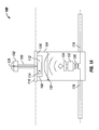
- Figure 1A illustrates a wirelessly powered lighting device 100 in an airfield lighting system, in accordance with example embodiments of the present disclosure.
- the lighting device 100 includes a light fixture 102, a base can 104, and a power delivery assembly 122.
- the power delivery assembly 122 is disposed within the can 104, and the light fixture 102 is mounted on or partially disposed in the can 104.
- the can 104 is disposed underground, or below grade, for example, deep under an airfield runway and the light fixture 102 is at ground level.
- the can 104 is made from a metallic material.
- the can 104 is made from a ferromagnetic material.
- the can 104 can be a vessel shaped like a cylinder, a box, or other shape.
- the base can 104 may be a 12 inch can.
- the light fixture 102 includes a base 110 which sits on or above the can 104.
- the base 110 may be at a ground level.
- the base 110 of the light fixture 102 covers an opening 126 of the can 104 such that the internal components of the can are not exposed.
- the light fixture 102 may be detached from the base can 104 by decoupling the base 110 from the base can 104.
- the can 104 may have a closed top end instead of the opening 126 without departing from the scope of this disclosure.
- the light fixture 102 also includes a riser column 106 which raises an emitting portion 128 of the light fixture 102 to a certain height or distance above grade.
- the base 110 includes an electronics compartment 108.
- the electronics compartment 108 is on an underside of the base 110 opposite the emitting portion 128, and is disposed within the can 104.
- the electronics compartment 108 includes a wireless power receiver 114 and other electronics for processing the received power and driving the emitting portion 128.
- a wireless power receiver 114 for processing the received power and driving the emitting portion 128.
- the electronics compartment 108 may be kept away from the water since it is held near the top of the can 104. Thus, the electronics of the light fixture 102 may be kept dry.
- the power delivery assembly 122 is coupled to an isolation transformer 120.
- the isolation transformer 120 is coupled to a power cable 116 which supplies a constant current from a power source (not shown) to the power delivery assembly 122.
- the power cable 116 enters the can 104 through an opening and exits the can 104 via another opening in the can 104.
- the isolation transformer 120 provides a means of transferring power from the power cable 116 or power source to the power delivery assembly 122 while isolating the power delivery assembly 122 from the power source.
- the power delivery assembly 122 is coupled to and delivers power to a wireless power transmitter 124.
- the wireless power transmitter 124 is wirelessly coupled to the wireless power receiver 114 of the light fixture 102.
- the wireless power transmitter 124 can transmit power wirelessly to the wireless power receiver 114.
- the power is then used to drive the emitting portion 128 of the light fixture 102.
- the wireless power receiver 114 provides power to a driver 112 which processes the power for use by the light fixture 102.
- the light fixture 102 does not need to be physically coupled to the power delivery assembly 122 or the power cable 116 via physical connections.
- the light fixture 102 can be easily removed from the can 104 for servicing or replacement.
- the wireless power transmitter 124 blocks the power cable 116 or isolation transformer 120 from being accessible from above the wireless power transmitter 124 as an additional safety measure.
- the wireless power transmitter 124 is configured in a way such that the power cable 116 and/or portions of the isolation transformer 120 are visible from above the wireless power transmitter 124. Such a configuration may include a coil in which gaps in the coil provide visibility.
- Figure 1B illustrates the wirelessly powered lighting device of FIG. 1A including a cover 130 that houses a transmitter of the wirelessly powered lighting device, in accordance with example embodiments of the present disclosure.
- the electronic compartment 108 and the cover 130 are disposed inside the base can 104.
- the cover 130 houses the transmitter 124.
- the cover 130 may protect the transmitter from exposure to water.
- the cover 130 may house the power delivery assembly 122 and the isolation transformer 120.
- the cover 130 may allow the transmitter 124 and the isolation transformer 120 to be operational underwater as shown by a possible water level 132.
- the transmitter 124 and the power delivery assembly 122 may be within the cover 130, and the isolation transformer 120 may be outside the cover 130.
- the cover 130 may have a shape other than shown in Figure 1B .
- FIG 2 illustrates a diagram of a wireless power transceiver 200 of the lighting device 100 of Figure 1A in an airfield lighting system, in accordance with example embodiments of the present disclosure.
- the wireless power transceiver 200 includes a transmitter circuit 202.
- the transmitter 124 of Figure 1A may include the transmitter circuit 202.
- the wireless power transceiver 200 also includes a receiver circuit 204.
- the receiver 114 of Figure 1A may include the receiver circuit 204.
- the wireless power transceiver 200 may receive power from the power delivery assembly 122 of Figure 1A .
- the transmitter circuit 202 includes a high-frequency power structure 206 such as a full or half H-bridge, an E-class amplifier, and the like.
- the high-frequency power structure 206 receives power from the power cable 116 via the isolation transformer 120 and the power delivery assembly 122.
- the power delivery assembly 122 may operate as the interface between the input current delivered by the isolation transformer 120 and the wireless power transmitter 124. To illustrate, the power delivery assembly 122may take the input current level from the isolation transformer and translate the current to the appropriate bus voltage for driving the wireless power transmitter 124. For example, thepower delivery assembly 122 may translate the current to approximately 30 to 75 VDC.
- the power deliver assembly 122 and the wireless power transmitter 124 could be combined in one assembly that performs both functions.
- the transmitter circuit 202 further includes a transmitter capacitor or resonant network 208 which is coupled to a transmitter coil 210.
- the transmitter capacitor or resonant network 208 may provide impedance matching.
- the receiver circuit 204 includes a receiver coil 212 and a receiver capacitor or resonant network 214.
- the transmitter resonant network 208 and the receiver resonant network 214 may be standard components of wireless power transfer technology, which places the transmitter coil 210 and the receiver coil 212 in resonance to enable efficient wireless power transfer between the wireless power transmitter 124 and the wireless power receiver 114.
- the coils 210, 212 are designed to be effective within the environment provided by the can 104.
- the configuration of the coils 210, 212 are designed depending on the shape and material of the base can 104.
- base can 104 may be a 12 inch can.
- the configuration of the coils 210, 212 may vary in size, number of coils, shape, and other attributes to maximize coupling between the coils or minimize the effect, like losses introduced by the presence of the metal can.
- the coils 210, 212 can be air coils made of wire or Litz wire, implemented on a PCB, or coils that include ferrites to increase coupling or decrease losses due to the presence of the can.
- the coils 210, 212 may each be a planar coil backed by a ferrite sheet.
- the receiver circuit 204 further includes a rectifier 216 which processes the received power for delivery to a light source 218.
- the rectifier 216 can be as simple as a passive diode rectifier or another AC/DC converter to drive the light source 218.
- Figure 2 illustrates an example of a wireless power interfacing scheme.
- Other embodiments of the present disclosure includes other known or new means of implementing wireless power transfer and the electronic elements required to do so.
- the lighting device 100 can include any of the systems and techniques described in U.S. Patent Application No. 14/681,561 .
- Figure 3 illustrates a schematic of an airfield lighting system 300 with wirelessly powered lighting devices 100, in accordance with example embodiments of the present disclosure.
- the airfield lighting system 300 includes a plurality of wirelessly powered lighting devices 100 coupled in series via the power cable 116.
- the system 300 includes a power source such as a constant current regulator 302 which provides power to the series of lighting devices 100 via the power cable 116.
- the constant current regulator 302 includes an output winding 304, a lightening arrestor 306, and a ground connection 308.
- one of the lighting devices 100 has a light fixture 102 (more clearly shown in Figure 1A ) that requires maintenance or replacement, that particular light fixture 102 can potentially be removed from the base can 104 of the particular lighting devices 100 without disrupting operation of the other lighting devices 100 and without the need to power down the entire system 300.
- an existing airfield lighting system can be retrofitted with the wirelessly power lighting devices 100.
- the wireless power transceiver 200 shown in Figure 2 can replace an existing wired light fixture and couple directly to the existing isolation transformer 120 or to the existing power delivery assembly 122.
- the entire wirelessly powered lighting device 100, including the base can 104 can replace an existing non-wireless lighting device by coupling directly to the power cable 116.
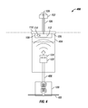
- FIG. 4 illustrates a wirelessly powered lighting device 400 in an airfield lighting system, in accordance with another example embodiment of the present disclosure.
- the lighting device 400 is similar to the lighting device 100 with the primary difference related to the location of the isolation transformer 120.
- the lighting device 400 includes the light fixture 102, a base can 404, and the power delivery assembly 122. Similar to the lighting device 100, the power delivery assembly 122 is disposed within the can 404, and the light fixture 102 is mounted on or partially disposed in the can 404.
- the base can 404 can be disposed underground or below grade, for example, deep under an airfield runway, and the light fixture 102 can be at ground level.
- the base can 404 is made from a metallic material.
- the base can 404 is made from a ferromagnetic material.
- the base can 404 can be a vessel shaped like a cylinder, a box, or other shape.
- the base can 404 may be an 8 inch shallow base can.
- the base can 404 is the same as the base can 104.
- the light fixture 102 may be coupled to the base can 404 substantially as described with respect to Figure 1A and the base can 104.
- the base 110 of the light fixture 102 may cover an opening 126 of the base can 404 such that the internal components of the can are not exposed.
- the can 104 may have a closed top end instead of the opening 126 without departing from the scope of this disclosure.
- the power delivery assembly 122 is coupled to the isolation transformer 120 that is outside of the base can 404.
- the power delivery assembly 122 may be coupled to the isolation transformer 120 via a second cable 406.
- the cable 406 may have a length in a range of 30 feet to 100 feet.
- the isolation transformer 120 may be placed in a concrete pit on a side of an airfield runway while the lighting device 100 is buried under the airfield runway.
- the second cable 406 may be shorter than 30 feet or longer than 100 feet.
- the isolation transformer 120 may be coupled to the power cable 116 that provides power to the power delivery assembly 122 through the isolation transformer 120 via the second cable 406.
- the second cable 406 enters the base can 404 through an opening, for example, at the bottom of the base can 404.
- the isolation transformer 120 provides a means of transferring power from the power cable 116 or power source to the power delivery assembly 122 while isolating the power delivery assembly 122 from the power source. Power is provided from the power delivery assembly 122 to the light fixture 102 in the same manner as described with the lighting device 100 of FIG. 1A .
- the light fixture 102 of the lighting device 400 does not need to be physically coupled to the power delivery assembly 122 or the power cable 116 via physical connections. Thus, the light fixture 102 can be easily removed from the base can 404 for servicing or replacement.
- the cover 130 may cover the transmitter 124 and the power delivery assembly 122 as described with respect to FIG. 1A .
- the cover 130 may be disposed in the base can 404 and protect the transmitter 124 and the power delivery assembly 122 from exposure to water.
- FIG 5 illustrates a schematic of an airfield lighting system 500 with wirelessly powered light devices 400, in accordance with another example embodiment of the present disclosure.
- the airfield lighting system 500 includes a plurality of wirelessly powered lighting devices 400 coupled in series via the power cable 116.
- the airfield lighting system 500 may be powered in the same manner as described with respect to the airfield lighting system 300 of Figure 3 .
- the isolation transformers 120 may be located off a runway and the base can 404 may be buried underneath the runway 504.
- the isolation transformers 120 may be placed in a concrete pit 502 that is on a side of the runway 504.
- the light fixtures 102 may be removed from the base can 404 without disrupting operation of the other light fixtures 102 and without the need to power down the entire system 500. Further, if one of the cans 104 along with its lighting fixture 102 and supporting components requires maintenance or replacement, the maintenance and replacement may be performed without shutting down the entire system 500.
- an existing airfield lighting system can be retrofitted with the wirelessly power lighting devices 400.
- the wireless power transceiver 200 shown in Figure 2 which can be used with the lighting device 400 in the same manner as described above, can replace an existing wired light fixture and couple directly to the existing isolation transformer 120 or to the existing power delivery assembly 122.
- the entire wirelessly powered lighting device 400, including the base can 404 can replace an existing non-wireless lighting device by coupling directly to the power cable 116.
Landscapes
- Engineering & Computer Science (AREA)
- Power Engineering (AREA)
- General Engineering & Computer Science (AREA)
- Physics & Mathematics (AREA)
- Acoustics & Sound (AREA)
- Mechanical Engineering (AREA)
- Aviation & Aerospace Engineering (AREA)
- Non-Portable Lighting Devices Or Systems Thereof (AREA)
- Arrangement Of Elements, Cooling, Sealing, Or The Like Of Lighting Devices (AREA)
- Circuit Arrangement For Electric Light Sources In General (AREA)
Abstract
Description
- The present application claims priority to
U.S. Provisional Patent Application No. 62/043,471 - Embodiments of the invention relate generally to airfield light fixtures, and more particularly to providing an airfield light fixture which receives power wirelessly from a power delivery assembly.
- Airfield lighting systems comprise a series of light fixtures that provide various visual signals for airfield operations. For example, a runway light system typically includes a plurality of individual light fixtures connected to a circuit. Specifically, the individual lights are connected to the circuit via current transformers, which ensures that in the event that one light fails, the rest of the lights along the circuit are still operational. Typically, each individual light fixture is mounted in a base can that is disposed underground, or integrated in the runway. These light fixtures are also typically located in the airfield, which is an outdoor environment open to the elements. A common cause of malfunctions in runway lights is water getting into the can and/or light fixture through connection points.
- Depending on how many individual lights are connected in series, the voltage of the power supply for this light system can be up to 5kV. Typically, each light fixture is physically connected to a power delivery assembly (which can include a current transformer) in the can which is coupled to a high-voltage circuit. Thus, in order to remove the light fixture from the can for servicing or replacement, the light fixture needs to be physically disconnected from the assembly. In most situations, in order to repair or service an individual light fixture, the whole system may need to be shut down such that a voltage is not applied through the power delivery assembly to which the affected light fixture is connected.
- The present disclosure relates generally to airfield light fixtures. In an example embodiment, a wirelessly powered airfield lighting device includes a base can and a wireless power transmitter disposed in the base can. The wireless power transmitter can wirelessly transmit power. The lighting device further includes an isolation transformer disposed inside the base can. The isolation transformer is electrically coupled to and between the wireless power transmitter and a power source. The lighting device also includes a light fixture that includes a base disposed on and sealing the top end of the base can and that includes an electronics compartment. The light fixture further includes a wireless power receiver disposed in the electronics compartment and that wirelessly receives power from the wireless power transmitter. The light fixture also includes a light source that receives power from the wireless power receiver.
- In another example embodiment, a wirelessly powered airfield lighting device includes a base canand a wireless power transmitter disposed in the base can. The wireless power transmitter can wirelessly transmit power. The lighting device further includes an isolation transformer disposed outside the base can. The isolation transformer is electrically coupled to and between the wireless power transmitter and a power source. The lighting device also includes a light fixture that includes a base disposed on and sealing the top end of the base can and that includes an electronics compartment. The light fixture further includes a wireless power receiver disposed in the electronics compartment and that wirelessly receives power from the wireless power transmitter. The light fixture also includes a light source that receives power from the wireless power receiver.
- In another example embodiment, a wirelessly powered airfield lighting system includes a constant current regulator to supply power and a plurality of wirelessly powered lighting devices. The plurality of wirelessly powered lighting devices receive power from the constant current regulator. Each wirelessly powered lighting device includes a base can and a wireless power transmitter disposed in the base can. The wireless power transmitter can wirelessly transmit power. Each lighting device further includes an isolation transformer disposed outside the base can. The isolation transformer is electrically coupled to and between the wireless power transmitter and a power source. Each lighting device also includes a light fixture that includes a base disposed on and sealing the top end of the base can and that includes an electronics compartment. The light fixture further includes a wireless power receiver disposed in the electronics compartment and that wirelessly receives power from the wireless power transmitter. The light fixture also includes a light source that receives power from the wireless power receiver.
- These and other aspects, objects, features, and embodiments will be apparent from the following description and the appended claims.
- Reference will now be made to the accompanying drawings, which are not necessarily drawn to scale, and wherein:
-
Figure 1A illustrates a wirelessly powered lighting device in an airfield lighting system, in accordance with example embodiments of the present disclosure; -
Figure 1B illustrates the wirelessly powered lighting device ofFIG. 1A including a cover that houses a transmitter of the wirelessly powered lighting device, in accordance with example embodiments of the present disclosure; -
Figure 2 illustrates a diagram of a wireless power transceiver of a lighting device in an airfield lighting system, in accordance with example embodiments of the present disclosure; -
Figure 3 illustrates a schematic of an airfield lighting system with wirelessly powered light fixtures, in accordance with example embodiments of the present disclosure; -
Figure 4 illustrates a wirelessly powered lighting device in an airfield lighting system, in accordance with other example embodiments of the present disclosure; and -
Figure 5 illustrates a schematic of an airfield lighting system with wirelessly powered light devices, in accordance with another example embodiment of the present disclosure. - The drawings illustrate only example embodiments of the invention and are therefore not to be considered limiting of its scope, as the invention may admit to other equally effective embodiments. In the drawings, reference numerals designate like or corresponding, but not necessarily identical, elements.
- In the following paragraphs, the present disclosure will be described in further detail by way of examples with reference to the attached drawings. In the description, well known components, methods, and/or processing techniques are omitted or briefly described so as not to obscure the disclosure. As used herein, the "present disclosure" refers to any one of the embodiments of the disclosure described herein and any equivalents. Furthermore, reference to various feature(s) of the "present disclosure" is not to suggest that all embodiments must include the referenced feature(s). Example embodiments disclosed herein are directed to wirelessly powering light fixtures in an airfield lighting system. Specifically, techniques disclosed herein allow removing a light fixture from the airfield lighting system without the need to handle high voltage power delivery connections. The capability to remove a light fixture from the airfield lighting system without the need to handle high voltage power delivery connections facilitates the process of servicing and replacement of individual light fixtures in the airfield lighting system.
- Referring to the drawings,
Figure 1A illustrates a wirelessly poweredlighting device 100 in an airfield lighting system, in accordance with example embodiments of the present disclosure. In certain example embodiments, thelighting device 100 includes alight fixture 102, a base can 104, and apower delivery assembly 122. In certain example embodiments, thepower delivery assembly 122 is disposed within thecan 104, and thelight fixture 102 is mounted on or partially disposed in thecan 104. In certain example applications, thecan 104 is disposed underground, or below grade, for example, deep under an airfield runway and thelight fixture 102 is at ground level. In certain example embodiments, thecan 104 is made from a metallic material. - In one example embodiment, the
can 104 is made from a ferromagnetic material. The can 104 can be a vessel shaped like a cylinder, a box, or other shape. For example, the base can 104 may be a 12 inch can. In certain example embodiments, thelight fixture 102 includes a base 110 which sits on or above thecan 104. For example, thebase 110 may be at a ground level. In certain such embodiments, thebase 110 of thelight fixture 102 covers anopening 126 of thecan 104 such that the internal components of the can are not exposed. For example, thelight fixture 102 may be detached from the base can 104 by decoupling the base 110 from the base can 104. In some alternative embodiments, thecan 104 may have a closed top end instead of theopening 126 without departing from the scope of this disclosure. In certain example embodiments, thelight fixture 102 also includes ariser column 106 which raises an emittingportion 128 of thelight fixture 102 to a certain height or distance above grade. In certain example embodiments, thebase 110 includes anelectronics compartment 108. In certain example embodiments, theelectronics compartment 108 is on an underside of the base 110 opposite the emittingportion 128, and is disposed within thecan 104. - The
electronics compartment 108 includes awireless power receiver 114 and other electronics for processing the received power and driving the emittingportion 128. In certain applications, when thelight device 100 is deployed in the field, a certain amount of water may accumulate in thecan 104. In such situations, theelectronics compartment 108 may be kept away from the water since it is held near the top of thecan 104. Thus, the electronics of thelight fixture 102 may be kept dry. - In certain example embodiments, the
power delivery assembly 122 is coupled to anisolation transformer 120. Theisolation transformer 120 is coupled to apower cable 116 which supplies a constant current from a power source (not shown) to thepower delivery assembly 122. In certain example embodiments, thepower cable 116 enters thecan 104 through an opening and exits thecan 104 via another opening in thecan 104. Theisolation transformer 120 provides a means of transferring power from thepower cable 116 or power source to thepower delivery assembly 122 while isolating thepower delivery assembly 122 from the power source. Thepower delivery assembly 122 is coupled to and delivers power to awireless power transmitter 124. Thewireless power transmitter 124 is wirelessly coupled to thewireless power receiver 114 of thelight fixture 102. Thewireless power transmitter 124 can transmit power wirelessly to thewireless power receiver 114. The power is then used to drive the emittingportion 128 of thelight fixture 102. In certain example embodiments, thewireless power receiver 114 provides power to adriver 112 which processes the power for use by thelight fixture 102. As such, thelight fixture 102 does not need to be physically coupled to thepower delivery assembly 122 or thepower cable 116 via physical connections. Thus, thelight fixture 102 can be easily removed from thecan 104 for servicing or replacement. - In certain example embodiments, the
wireless power transmitter 124, or a separate barrier adjacent to thetransmitter 124, blocks thepower cable 116 orisolation transformer 120 from being accessible from above thewireless power transmitter 124 as an additional safety measure. In certain example embodiments, thewireless power transmitter 124 is configured in a way such that thepower cable 116 and/or portions of theisolation transformer 120 are visible from above thewireless power transmitter 124. Such a configuration may include a coil in which gaps in the coil provide visibility. -
Figure 1B illustrates the wirelessly powered lighting device ofFIG. 1A including acover 130 that houses a transmitter of the wirelessly powered lighting device, in accordance with example embodiments of the present disclosure. Referring toFigures 1A and1B , in some example embodiments, theelectronic compartment 108 and thecover 130 are disposed inside the base can 104. Thecover 130 houses thetransmitter 124. For example, thecover 130 may protect the transmitter from exposure to water. Further, thecover 130 may house thepower delivery assembly 122 and theisolation transformer 120. For example, thecover 130 may allow thetransmitter 124 and theisolation transformer 120 to be operational underwater as shown by a possible water level 132.In some example embodiments, thetransmitter 124 and thepower delivery assembly 122 may be within thecover 130, and theisolation transformer 120 may be outside thecover 130. In some alternative embodiments, thecover 130 may have a shape other than shown inFigure 1B . -
Figure 2 illustrates a diagram of awireless power transceiver 200 of thelighting device 100 ofFigure 1A in an airfield lighting system, in accordance with example embodiments of the present disclosure. Thewireless power transceiver 200 includes atransmitter circuit 202. For example, thetransmitter 124 ofFigure 1A may include thetransmitter circuit 202. Thewireless power transceiver 200 also includes areceiver circuit 204. For example, thereceiver 114 ofFigure 1A may include thereceiver circuit 204. To illustrate, thewireless power transceiver 200 may receive power from thepower delivery assembly 122 ofFigure 1A . - In certain example embodiments, the
transmitter circuit 202 includes a high-frequency power structure 206 such as a full or half H-bridge, an E-class amplifier, and the like. In some example embodiments, the high-frequency power structure 206 receives power from thepower cable 116 via theisolation transformer 120 and thepower delivery assembly 122. The power delivery assembly 122may operate as the interface between the input current delivered by theisolation transformer 120 and thewireless power transmitter 124. To illustrate, the power delivery assembly 122may take the input current level from the isolation transformer and translate the current to the appropriate bus voltage for driving thewireless power transmitter 124. For example, thepowerdelivery assembly 122 may translate the current to approximately 30 to 75 VDC. In some example embodiments, the power deliverassembly 122 and thewireless power transmitter 124 could be combined in one assembly that performs both functions.Thetransmitter circuit 202 further includes a transmitter capacitor orresonant network 208 which is coupled to atransmitter coil 210. The transmitter capacitor orresonant network 208 may provide impedance matching. - In certain example embodiments, the
receiver circuit 204 includes areceiver coil 212 and a receiver capacitor orresonant network 214. The transmitterresonant network 208 and the receiverresonant network 214 may be standard components of wireless power transfer technology, which places thetransmitter coil 210 and thereceiver coil 212 in resonance to enable efficient wireless power transfer between thewireless power transmitter 124 and thewireless power receiver 114. - In certain example embodiments, the
coils can 104. To illustrate, the configuration of thecoils coils coils coils - In certain example embodiments, the
receiver circuit 204 further includes arectifier 216 which processes the received power for delivery to alight source 218. Therectifier 216 can be as simple as a passive diode rectifier or another AC/DC converter to drive thelight source 218. -
Figure 2 illustrates an example of a wireless power interfacing scheme. Other embodiments of the present disclosure includes other known or new means of implementing wireless power transfer and the electronic elements required to do so. In certain example embodiments, thelighting device 100 can include any of the systems and techniques described inU.S. Patent Application No. 14/681,561 . -
Figure 3 illustrates a schematic of anairfield lighting system 300 with wirelesslypowered lighting devices 100, in accordance with example embodiments of the present disclosure. In certain example embodiments, theairfield lighting system 300 includes a plurality of wirelesslypowered lighting devices 100 coupled in series via thepower cable 116. In certain example embodiments, thesystem 300 includes a power source such as a constantcurrent regulator 302 which provides power to the series oflighting devices 100 via thepower cable 116. In certain example embodiments, the constantcurrent regulator 302 includes an output winding 304, a lighteningarrestor 306, and aground connection 308. In certain example embodiments, if one of thelighting devices 100 has a light fixture 102 (more clearly shown inFigure 1A ) that requires maintenance or replacement, that particularlight fixture 102 can potentially be removed from the base can 104 of theparticular lighting devices 100 without disrupting operation of theother lighting devices 100 and without the need to power down theentire system 300. - In certain example embodiments, an existing airfield lighting system can be retrofitted with the wirelessly
power lighting devices 100. To illustrate, in some example embodiments, thewireless power transceiver 200 shown inFigure 2 can replace an existing wired light fixture and couple directly to the existingisolation transformer 120 or to the existingpower delivery assembly 122. In another example embodiment, the entire wirelesslypowered lighting device 100, including the base can 104, can replace an existing non-wireless lighting device by coupling directly to thepower cable 116. -
Figure 4 illustrates a wirelesslypowered lighting device 400 in an airfield lighting system, in accordance with another example embodiment of the present disclosure. Thelighting device 400 is similar to thelighting device 100 with the primary difference related to the location of theisolation transformer 120. To illustrate, in some example embodiments, thelighting device 400 includes thelight fixture 102, a base can 404, and thepower delivery assembly 122. Similar to thelighting device 100, thepower delivery assembly 122 is disposed within thecan 404, and thelight fixture 102 is mounted on or partially disposed in thecan 404. In certain example applications, the base can 404 can be disposed underground or below grade, for example, deep under an airfield runway, and thelight fixture 102 can be at ground level. In certain example embodiments, the base can 404 is made from a metallic material. - In one example embodiment, the base can 404 is made from a ferromagnetic material. The base can 404 can be a vessel shaped like a cylinder, a box, or other shape. For example, the base can 404 may be an 8 inch shallow base can. In some example embodiments, the base can 404 is the same as the base can 104. The
light fixture 102 may be coupled to the base can 404 substantially as described with respect toFigure 1A and the base can 104. For example, thebase 110 of thelight fixture 102 may cover anopening 126 of the base can 404 such that the internal components of the can are not exposed. In some alternative embodiments, thecan 104 may have a closed top end instead of theopening 126 without departing from the scope of this disclosure. - In certain example embodiments, the
power delivery assembly 122 is coupled to theisolation transformer 120 that is outside of the base can 404. To illustrate, thepower delivery assembly 122 may be coupled to theisolation transformer 120 via asecond cable 406. For example, thecable 406 may have a length in a range of 30 feet to 100 feet. To illustrate, theisolation transformer 120 may be placed in a concrete pit on a side of an airfield runway while thelighting device 100 is buried under the airfield runway. In some alternative embodiments, thesecond cable 406 may be shorter than 30 feet or longer than 100 feet. - As illustrated in
Figure 4 , theisolation transformer 120 may be coupled to thepower cable 116 that provides power to thepower delivery assembly 122 through theisolation transformer 120 via thesecond cable 406. In certain example embodiments, thesecond cable 406 enters the base can 404 through an opening, for example, at the bottom of the base can 404. Theisolation transformer 120 provides a means of transferring power from thepower cable 116 or power source to thepower delivery assembly 122 while isolating thepower delivery assembly 122 from the power source. Power is provided from thepower delivery assembly 122 to thelight fixture 102 in the same manner as described with thelighting device 100 ofFIG. 1A . As is the case with thelighting device 100, thelight fixture 102 of thelighting device 400 does not need to be physically coupled to thepower delivery assembly 122 or thepower cable 116 via physical connections. Thus, thelight fixture 102 can be easily removed from the base can 404 for servicing or replacement. - In some example embodiments, the cover 130 (shown in
Figure 1B ) may cover thetransmitter 124 and thepower delivery assembly 122 as described with respect toFIG. 1A . For example, thecover 130 may be disposed in the base can 404 and protect thetransmitter 124 and thepower delivery assembly 122 from exposure to water. -
Figure 5 illustrates a schematic of an airfield lighting system 500 with wirelessly poweredlight devices 400, in accordance with another example embodiment of the present disclosure. The airfield lighting system 500 includes a plurality of wirelesslypowered lighting devices 400 coupled in series via thepower cable 116. The airfield lighting system 500 may be powered in the same manner as described with respect to theairfield lighting system 300 ofFigure 3 . As illustrated inFigure 5 , theisolation transformers 120 may be located off a runway and the base can 404 may be buried underneath therunway 504. For example, theisolation transformers 120 may be placed in aconcrete pit 502 that is on a side of therunway 504. - In certain example embodiments, if one of the
light fixtures 102 requires maintenance or replacement, that particularlight fixture 102 may be removed from the base can 404 without disrupting operation of the otherlight fixtures 102 and without the need to power down the entire system 500. Further, if one of thecans 104 along with itslighting fixture 102 and supporting components requires maintenance or replacement, the maintenance and replacement may be performed without shutting down the entire system 500. - In certain example embodiments, an existing airfield lighting system can be retrofitted with the wirelessly
power lighting devices 400. To illustrate, in some example embodiments, thewireless power transceiver 200 shown inFigure 2 , which can be used with thelighting device 400 in the same manner as described above, can replace an existing wired light fixture and couple directly to the existingisolation transformer 120 or to the existingpower delivery assembly 122. In another example embodiment, the entire wirelesslypowered lighting device 400, including the base can 404, can replace an existing non-wireless lighting device by coupling directly to thepower cable 116. - Although particular embodiments have been described herein in detail, the descriptions are by way of example. The features of the example embodiments described herein are representative and, in alternative embodiments, certain features, elements, and/or steps may be added or omitted. Additionally, modifications to aspects of the example embodiments described herein may be made by those skilled in the art without departing from the spirit and scope of the following claims, the scope of which are to be accorded the broadest interpretation so as to encompass modifications and equivalent structures.
-
- 1. A wirelessly powered airfield lighting device, comprising:
- a base can;
- a wireless power transmitter disposed in the base can, the wireless power transmitter to wirelessly transmit power;
- an isolation transformer disposed outside the base can, wherein the isolation transformer is electrically coupled to and between the wireless power transmitter and a power source; and
- a light fixture comprising:
- a base disposed on and sealing the top end of the base can, the base comprising an electronics compartment;
- a wireless power receiver disposed in the electronics compartment and to wirelessly receive power from the wireless power transmitter; and
- a light source to receive power from the wireless power receiver.
- 2. The wirelessly powered airfield lighting device of 1, further comprising a cover disposed in the base can, wherein the cover houses the wireless power transmitter and wherein the cover protects the wireless power transmitter from exposure to water.
- 3. The wirelessly powered airfield lighting device of 1, wherein the light source is disposed on top of the base and wherein the electronics compartment is disposed on the bottom of the base opposite the light source.
- 4. The wirelessly powered airfield lighting device of Claim 3, wherein the electronics compartment is disposed within the base can.
- 5. The wirelessly powered airfield lighting device of 1, wherein the light fixture is detachable from the base can by decoupling the base from the base can.
- 6. A wirelessly powered airfield lighting system, comprising:
- a constant current regulator to supply power; and
- a plurality of wirelessly powered lighting devices, the plurality of wirelessly powered lighting devices receiving power from the constant current regulator, wherein each wirelessly powered lighting device comprises:
- a wireless power transmitter disposed in a base can, the wireless power transmitter to wirelessly transmit power;
- an isolation transformer, wherein the isolation transformer is electrically coupled to and between the wireless power transmitter and a power source; and
- a light fixture comprising:
- a base disposed on and sealing the top end of the base can, the base comprising an electronics compartment;
- a wireless power receiver disposed in the electronics compartment and to wirelessly receive power from the wireless power transmitter; and
- a light source to receive power from the wireless power receiver.
- 7. The wirelessly powered airfield lighting system of 6, wherein the plurality of wirelessly powered lighting devices are electrically coupled together in series.
- 8. The wirelessly powered airfield lighting system of Claim 6, wherein isolation transformer is disposed inside the base can.
- 9. The wirelessly powered airfield lighting system of Claim 6, wherein isolation transformer is disposed outside the base can.
- 10. The wirelessly powered airfield lighting system of Claim 6, wherein the light fixture of each wirelessly powered lighting device is detachable from the base can without disconnect the power from the constant current regulator.
Claims (10)
- A wirelessly powered airfield lighting device, comprising:a base can;a wireless power transmitter disposed in the base can, the wireless power transmitter to wirelessly transmit power;an isolation transformer disposed inside the base can, wherein the isolation transformer is electrically coupled to and between the wireless power transmitter and a power source; anda light fixture comprising:a base disposed on and sealing the top end of the base can, the base comprising an electronics compartment;a wireless power receiver disposed in the electronics compartment and to wirelessly receive power from the wireless power transmitter; anda light source to receive power from the wireless power receiver.
- The wirelessly powered airfield lighting device of Claim 1, further comprising a cover disposed in the base can, wherein the cover houses the wireless power transmitter.
- The wirelessly powered airfield lighting device of Claim 2, wherein the cover protects the wireless power transmitter from exposure to water.
- The wirelessly powered airfield lighting device of Claim 1, wherein the wireless power transmitter is disposed between the isolation transformer and the wireless power receiver.
- The wirelessly powered airfield lighting device of Claim 1, wherein the light source is disposed on top of the base and wherein the electronics compartment is disposed on the bottom of the base opposite the light source.
- The wirelessly powered airfield lighting device of Claim 5, wherein the electronics compartment is disposed within the base can.
- The wirelessly powered airfield lighting device of Claim 1, wherein the light source is disposed within the base.
- The wirelessly powered airfield lighting device of Claim 1, wherein the light fixture is detachable from the base can by decoupling the base from the base can.
- The wirelessly powered airfield lighting device of Claim 8, wherein the light fixture is detachable from the base can without removing the wireless power transmitter from inside the base can.
- The wirelessly powered airfield lighting device of Claim 1, wherein the isolation transformer is coupled to the power source using a cable and wherein the light fixture is detachable from the base can without decoupling the isolation transformer from the power source.
Applications Claiming Priority (1)
| Application Number | Priority Date | Filing Date | Title |
|---|---|---|---|
| US201462043471P | 2014-08-29 | 2014-08-29 |
Publications (3)
| Publication Number | Publication Date |
|---|---|
| EP2991457A2 true EP2991457A2 (en) | 2016-03-02 |
| EP2991457A3 EP2991457A3 (en) | 2016-06-08 |
| EP2991457B1 EP2991457B1 (en) | 2018-11-14 |
Family
ID=54014645
Family Applications (1)
| Application Number | Title | Priority Date | Filing Date |
|---|---|---|---|
| EP15183148.4A Not-in-force EP2991457B1 (en) | 2014-08-29 | 2015-08-31 | Wireless power for airfield lighting |
Country Status (3)
| Country | Link |
|---|---|
| US (1) | US10119693B2 (en) |
| EP (1) | EP2991457B1 (en) |
| ES (1) | ES2701329T3 (en) |
Cited By (3)
| Publication number | Priority date | Publication date | Assignee | Title |
|---|---|---|---|---|
| WO2018001785A1 (en) * | 2016-06-30 | 2018-01-04 | Philips Lighting Holding B.V. | Lighting device and power distribution |
| WO2018211156A3 (en) * | 2017-04-03 | 2019-01-03 | Santos Francisco Laserna Larburu | Wireless beacon |
| WO2019182446A1 (en) * | 2018-03-21 | 2019-09-26 | Orga Holding B.V. | Obstacle lighting unit and method for changing an obstacle lighting unit configuration |
Families Citing this family (3)
| Publication number | Priority date | Publication date | Assignee | Title |
|---|---|---|---|---|
| AU2017395527B2 (en) * | 2017-01-27 | 2021-01-28 | HotaluX, Ltd. | Chained flashlight system |
| CN112178521A (en) * | 2019-07-03 | 2021-01-05 | 黄涛 | Mutual inductance modular light-emitting lamp device |
| US20220131416A1 (en) * | 2020-10-22 | 2022-04-28 | Powermat Technologies Ltd. | Wireless illumination |
Family Cites Families (7)
| Publication number | Priority date | Publication date | Assignee | Title |
|---|---|---|---|---|
| US3316447A (en) | 1960-10-03 | 1967-04-25 | Strong Electric Corp | Inductively energized unit with means to impede primary current flow |
| FR2695285B3 (en) * | 1992-09-02 | 1994-07-29 | Cableco Sa | LIGHTING ASSEMBLY COMPRISING A LAMP SUPPLIED BY THE SECTOR. |
| US20060232957A1 (en) | 2005-04-15 | 2006-10-19 | Roger Bieberdorf | Airport light base installation with non-conductive isolation transformer support |
| US20080001782A1 (en) * | 2006-06-30 | 2008-01-03 | Cooper Technologies Company | Airfield lighting system and method |
| DE102010014948A1 (en) * | 2010-04-14 | 2011-10-20 | Hella Kgaa Hueck & Co. | Arrangement for energetic supply of light unit e.g. organic LED, for vehicle, has structure component comprising coil with lead lines, where self-contained housing and structure component are galvanically separated |
| JP5573439B2 (en) * | 2010-07-09 | 2014-08-20 | Tdk株式会社 | Wireless power supply device, light source cartridge, and wireless lighting system |
| US8502464B2 (en) * | 2011-02-18 | 2013-08-06 | Control Solutions LLC | Underwater lighting system and method |
-
2015
- 2015-08-28 US US14/839,397 patent/US10119693B2/en active Active
- 2015-08-31 ES ES15183148T patent/ES2701329T3/en active Active
- 2015-08-31 EP EP15183148.4A patent/EP2991457B1/en not_active Not-in-force
Cited By (4)
| Publication number | Priority date | Publication date | Assignee | Title |
|---|---|---|---|---|
| WO2018001785A1 (en) * | 2016-06-30 | 2018-01-04 | Philips Lighting Holding B.V. | Lighting device and power distribution |
| WO2018211156A3 (en) * | 2017-04-03 | 2019-01-03 | Santos Francisco Laserna Larburu | Wireless beacon |
| WO2019182446A1 (en) * | 2018-03-21 | 2019-09-26 | Orga Holding B.V. | Obstacle lighting unit and method for changing an obstacle lighting unit configuration |
| NL2020639B1 (en) * | 2018-03-21 | 2019-10-02 | Orga Holding B V | Obstacle lighting unit and method for changing an obstacle lighting unit configuration |
Also Published As
| Publication number | Publication date |
|---|---|
| EP2991457B1 (en) | 2018-11-14 |
| US20160061430A1 (en) | 2016-03-03 |
| ES2701329T3 (en) | 2019-02-21 |
| US10119693B2 (en) | 2018-11-06 |
| EP2991457A3 (en) | 2016-06-08 |
Similar Documents
| Publication | Publication Date | Title |
|---|---|---|
| US10119693B2 (en) | Wireless power for airfield lighting | |
| US10158253B2 (en) | Wireless power relay device and wireless power transmission system | |
| US11062841B2 (en) | Electromagnetic shield device, wireless charging transmitting terminal, wireless charging receiving terminal and system | |
| US8517593B2 (en) | Wireless power feeder, light source cartridge, and wireless illumination system | |
| US20160248280A1 (en) | System and method for triggering power transfer across an inductive power coupling and non resonant transmission | |
| EP3000643A8 (en) | Electrical powered vehicle and power feeding device for vehicle | |
| JP2012049434A (en) | Electronic component, feeder device, power receiver, and wireless feeder system | |
| US10439422B2 (en) | Wireless power transfer to a medical computer cart | |
| US20190296588A1 (en) | Wireless power transfer ecosystem and coils operating on substantially different power levels | |
| CN203434660U (en) | Wireless charging device of portable device | |
| WO2010091202A1 (en) | Wireless power transfer with lighting | |
| EP2582064B1 (en) | Wireless power repeater | |
| US20160100528A1 (en) | Lighting system for plant cultivation | |
| MX2017008400A (en) | Illuminated vehicle charging system. | |
| JP6331902B2 (en) | Power transmission equipment | |
| US11742699B2 (en) | Power feeding device and power feeding system | |
| CA2904740A1 (en) | Wireless power system | |
| CN103630732B (en) | Isolated passive high voltage charge indicating device | |
| WO2012158700A3 (en) | Extended reach rechargeable lighting systems | |
| CN204832380U (en) | Novel voltage transformer error checking equipment | |
| CN103051071A (en) | Desktop load power supply device based on wireless energy transmission | |
| US10770922B2 (en) | Resonant inductive converter | |
| US10784043B2 (en) | Wireless power transmission device, wireless power reception device, and wireless charging system | |
| EP3302005A1 (en) | Obstructions lighting system and process having operating modes | |
| TW200407805A (en) | Power line warning light |
Legal Events
| Date | Code | Title | Description |
|---|---|---|---|
| PUAI | Public reference made under article 153(3) epc to a published international application that has entered the european phase |
Free format text: ORIGINAL CODE: 0009012 |
|
| 17P | Request for examination filed |
Effective date: 20151028 |
|
| AK | Designated contracting states |
Kind code of ref document: A2 Designated state(s): AL AT BE BG CH CY CZ DE DK EE ES FI FR GB GR HR HU IE IS IT LI LT LU LV MC MK MT NL NO PL PT RO RS SE SI SK SM TR |
|
| AX | Request for extension of the european patent |
Extension state: BA ME |
|
| REG | Reference to a national code |
Ref country code: DE Ref legal event code: R079 Ref document number: 602015019739 Country of ref document: DE Free format text: PREVIOUS MAIN CLASS: H05B0037030000 Ipc: H05B0037020000 |
|
| PUAL | Search report despatched |
Free format text: ORIGINAL CODE: 0009013 |
|
| AK | Designated contracting states |
Kind code of ref document: A3 Designated state(s): AL AT BE BG CH CY CZ DE DK EE ES FI FR GB GR HR HU IE IS IT LI LT LU LV MC MK MT NL NO PL PT RO RS SE SI SK SM TR |
|
| AX | Request for extension of the european patent |
Extension state: BA ME |
|
| RIC1 | Information provided on ipc code assigned before grant |
Ipc: F21V 23/00 20150101ALI20160502BHEP Ipc: B64F 1/20 20060101ALI20160502BHEP Ipc: H05B 37/03 20060101ALI20160502BHEP Ipc: H01F 38/14 20060101ALI20160502BHEP Ipc: H05B 37/02 20060101AFI20160502BHEP Ipc: F21V 23/02 20060101ALI20160502BHEP |
|
| RBV | Designated contracting states (corrected) |
Designated state(s): AL AT BE BG CH CY CZ DE DK EE ES FI FR GB GR HR HU IE IS IT LI LT LU LV MC MK MT NL NO PL PT RO RS SE SI SK SM TR |
|
| STAA | Information on the status of an ep patent application or granted ep patent |
Free format text: STATUS: EXAMINATION IS IN PROGRESS |
|
| 17Q | First examination report despatched |
Effective date: 20170519 |
|
| GRAP | Despatch of communication of intention to grant a patent |
Free format text: ORIGINAL CODE: EPIDOSNIGR1 |
|
| STAA | Information on the status of an ep patent application or granted ep patent |
Free format text: STATUS: GRANT OF PATENT IS INTENDED |
|
| INTG | Intention to grant announced |
Effective date: 20180607 |
|
| GRAS | Grant fee paid |
Free format text: ORIGINAL CODE: EPIDOSNIGR3 |
|
| GRAA | (expected) grant |
Free format text: ORIGINAL CODE: 0009210 |
|
| STAA | Information on the status of an ep patent application or granted ep patent |
Free format text: STATUS: THE PATENT HAS BEEN GRANTED |
|
| AK | Designated contracting states |
Kind code of ref document: B1 Designated state(s): AL AT BE BG CH CY CZ DE DK EE ES FI FR GB GR HR HU IE IS IT LI LT LU LV MC MK MT NL NO PL PT RO RS SE SI SK SM TR |
|
| REG | Reference to a national code |
Ref country code: CH Ref legal event code: EP Ref country code: AT Ref legal event code: REF Ref document number: 1066389 Country of ref document: AT Kind code of ref document: T Effective date: 20181115 |
|
| REG | Reference to a national code |
Ref country code: DE Ref legal event code: R096 Ref document number: 602015019739 Country of ref document: DE |
|
| REG | Reference to a national code |
Ref country code: IE Ref legal event code: FG4D |
|
| REG | Reference to a national code |
Ref country code: ES Ref legal event code: FG2A Ref document number: 2701329 Country of ref document: ES Kind code of ref document: T3 Effective date: 20190221 |
|
| REG | Reference to a national code |
Ref country code: NL Ref legal event code: MP Effective date: 20181114 |
|
| REG | Reference to a national code |
Ref country code: LT Ref legal event code: MG4D |
|
| REG | Reference to a national code |
Ref country code: AT Ref legal event code: MK05 Ref document number: 1066389 Country of ref document: AT Kind code of ref document: T Effective date: 20181114 |
|
| PG25 | Lapsed in a contracting state [announced via postgrant information from national office to epo] |
Ref country code: FI Free format text: LAPSE BECAUSE OF FAILURE TO SUBMIT A TRANSLATION OF THE DESCRIPTION OR TO PAY THE FEE WITHIN THE PRESCRIBED TIME-LIMIT Effective date: 20181114 Ref country code: BG Free format text: LAPSE BECAUSE OF FAILURE TO SUBMIT A TRANSLATION OF THE DESCRIPTION OR TO PAY THE FEE WITHIN THE PRESCRIBED TIME-LIMIT Effective date: 20190214 Ref country code: HR Free format text: LAPSE BECAUSE OF FAILURE TO SUBMIT A TRANSLATION OF THE DESCRIPTION OR TO PAY THE FEE WITHIN THE PRESCRIBED TIME-LIMIT Effective date: 20181114 Ref country code: LV Free format text: LAPSE BECAUSE OF FAILURE TO SUBMIT A TRANSLATION OF THE DESCRIPTION OR TO PAY THE FEE WITHIN THE PRESCRIBED TIME-LIMIT Effective date: 20181114 Ref country code: AT Free format text: LAPSE BECAUSE OF FAILURE TO SUBMIT A TRANSLATION OF THE DESCRIPTION OR TO PAY THE FEE WITHIN THE PRESCRIBED TIME-LIMIT Effective date: 20181114 Ref country code: LT Free format text: LAPSE BECAUSE OF FAILURE TO SUBMIT A TRANSLATION OF THE DESCRIPTION OR TO PAY THE FEE WITHIN THE PRESCRIBED TIME-LIMIT Effective date: 20181114 Ref country code: NO Free format text: LAPSE BECAUSE OF FAILURE TO SUBMIT A TRANSLATION OF THE DESCRIPTION OR TO PAY THE FEE WITHIN THE PRESCRIBED TIME-LIMIT Effective date: 20190214 Ref country code: IS Free format text: LAPSE BECAUSE OF FAILURE TO SUBMIT A TRANSLATION OF THE DESCRIPTION OR TO PAY THE FEE WITHIN THE PRESCRIBED TIME-LIMIT Effective date: 20190314 |
|
| PG25 | Lapsed in a contracting state [announced via postgrant information from national office to epo] |
Ref country code: NL Free format text: LAPSE BECAUSE OF FAILURE TO SUBMIT A TRANSLATION OF THE DESCRIPTION OR TO PAY THE FEE WITHIN THE PRESCRIBED TIME-LIMIT Effective date: 20181114 Ref country code: PT Free format text: LAPSE BECAUSE OF FAILURE TO SUBMIT A TRANSLATION OF THE DESCRIPTION OR TO PAY THE FEE WITHIN THE PRESCRIBED TIME-LIMIT Effective date: 20190314 Ref country code: RS Free format text: LAPSE BECAUSE OF FAILURE TO SUBMIT A TRANSLATION OF THE DESCRIPTION OR TO PAY THE FEE WITHIN THE PRESCRIBED TIME-LIMIT Effective date: 20181114 Ref country code: GR Free format text: LAPSE BECAUSE OF FAILURE TO SUBMIT A TRANSLATION OF THE DESCRIPTION OR TO PAY THE FEE WITHIN THE PRESCRIBED TIME-LIMIT Effective date: 20190215 Ref country code: AL Free format text: LAPSE BECAUSE OF FAILURE TO SUBMIT A TRANSLATION OF THE DESCRIPTION OR TO PAY THE FEE WITHIN THE PRESCRIBED TIME-LIMIT Effective date: 20181114 Ref country code: SE Free format text: LAPSE BECAUSE OF FAILURE TO SUBMIT A TRANSLATION OF THE DESCRIPTION OR TO PAY THE FEE WITHIN THE PRESCRIBED TIME-LIMIT Effective date: 20181114 |
|
| PG25 | Lapsed in a contracting state [announced via postgrant information from national office to epo] |
Ref country code: CZ Free format text: LAPSE BECAUSE OF FAILURE TO SUBMIT A TRANSLATION OF THE DESCRIPTION OR TO PAY THE FEE WITHIN THE PRESCRIBED TIME-LIMIT Effective date: 20181114 Ref country code: DK Free format text: LAPSE BECAUSE OF FAILURE TO SUBMIT A TRANSLATION OF THE DESCRIPTION OR TO PAY THE FEE WITHIN THE PRESCRIBED TIME-LIMIT Effective date: 20181114 Ref country code: PL Free format text: LAPSE BECAUSE OF FAILURE TO SUBMIT A TRANSLATION OF THE DESCRIPTION OR TO PAY THE FEE WITHIN THE PRESCRIBED TIME-LIMIT Effective date: 20181114 |
|
| REG | Reference to a national code |
Ref country code: DE Ref legal event code: R097 Ref document number: 602015019739 Country of ref document: DE |
|
| PG25 | Lapsed in a contracting state [announced via postgrant information from national office to epo] |
Ref country code: EE Free format text: LAPSE BECAUSE OF FAILURE TO SUBMIT A TRANSLATION OF THE DESCRIPTION OR TO PAY THE FEE WITHIN THE PRESCRIBED TIME-LIMIT Effective date: 20181114 Ref country code: SM Free format text: LAPSE BECAUSE OF FAILURE TO SUBMIT A TRANSLATION OF THE DESCRIPTION OR TO PAY THE FEE WITHIN THE PRESCRIBED TIME-LIMIT Effective date: 20181114 Ref country code: SK Free format text: LAPSE BECAUSE OF FAILURE TO SUBMIT A TRANSLATION OF THE DESCRIPTION OR TO PAY THE FEE WITHIN THE PRESCRIBED TIME-LIMIT Effective date: 20181114 Ref country code: RO Free format text: LAPSE BECAUSE OF FAILURE TO SUBMIT A TRANSLATION OF THE DESCRIPTION OR TO PAY THE FEE WITHIN THE PRESCRIBED TIME-LIMIT Effective date: 20181114 |
|
| PLBE | No opposition filed within time limit |
Free format text: ORIGINAL CODE: 0009261 |
|
| STAA | Information on the status of an ep patent application or granted ep patent |
Free format text: STATUS: NO OPPOSITION FILED WITHIN TIME LIMIT |
|
| 26N | No opposition filed |
Effective date: 20190815 |
|
| PG25 | Lapsed in a contracting state [announced via postgrant information from national office to epo] |
Ref country code: SI Free format text: LAPSE BECAUSE OF FAILURE TO SUBMIT A TRANSLATION OF THE DESCRIPTION OR TO PAY THE FEE WITHIN THE PRESCRIBED TIME-LIMIT Effective date: 20181114 |
|
| PG25 | Lapsed in a contracting state [announced via postgrant information from national office to epo] |
Ref country code: TR Free format text: LAPSE BECAUSE OF FAILURE TO SUBMIT A TRANSLATION OF THE DESCRIPTION OR TO PAY THE FEE WITHIN THE PRESCRIBED TIME-LIMIT Effective date: 20181114 |
|
| PG25 | Lapsed in a contracting state [announced via postgrant information from national office to epo] |
Ref country code: LI Free format text: LAPSE BECAUSE OF NON-PAYMENT OF DUE FEES Effective date: 20190831 Ref country code: CH Free format text: LAPSE BECAUSE OF NON-PAYMENT OF DUE FEES Effective date: 20190831 Ref country code: MC Free format text: LAPSE BECAUSE OF FAILURE TO SUBMIT A TRANSLATION OF THE DESCRIPTION OR TO PAY THE FEE WITHIN THE PRESCRIBED TIME-LIMIT Effective date: 20181114 Ref country code: LU Free format text: LAPSE BECAUSE OF NON-PAYMENT OF DUE FEES Effective date: 20190831 |
|
| PG25 | Lapsed in a contracting state [announced via postgrant information from national office to epo] |
Ref country code: IE Free format text: LAPSE BECAUSE OF NON-PAYMENT OF DUE FEES Effective date: 20190831 |
|
| PGFP | Annual fee paid to national office [announced via postgrant information from national office to epo] |
Ref country code: ES Payment date: 20200901 Year of fee payment: 6 Ref country code: GB Payment date: 20200722 Year of fee payment: 6 Ref country code: FR Payment date: 20200721 Year of fee payment: 6 Ref country code: DE Payment date: 20200721 Year of fee payment: 6 |
|
| PGFP | Annual fee paid to national office [announced via postgrant information from national office to epo] |
Ref country code: BE Payment date: 20200724 Year of fee payment: 6 Ref country code: IT Payment date: 20200721 Year of fee payment: 6 |
|
| PG25 | Lapsed in a contracting state [announced via postgrant information from national office to epo] |
Ref country code: CY Free format text: LAPSE BECAUSE OF FAILURE TO SUBMIT A TRANSLATION OF THE DESCRIPTION OR TO PAY THE FEE WITHIN THE PRESCRIBED TIME-LIMIT Effective date: 20181114 |
|
| PG25 | Lapsed in a contracting state [announced via postgrant information from national office to epo] |
Ref country code: HU Free format text: LAPSE BECAUSE OF FAILURE TO SUBMIT A TRANSLATION OF THE DESCRIPTION OR TO PAY THE FEE WITHIN THE PRESCRIBED TIME-LIMIT; INVALID AB INITIO Effective date: 20150831 Ref country code: MT Free format text: LAPSE BECAUSE OF FAILURE TO SUBMIT A TRANSLATION OF THE DESCRIPTION OR TO PAY THE FEE WITHIN THE PRESCRIBED TIME-LIMIT Effective date: 20181114 |
|
| REG | Reference to a national code |
Ref country code: DE Ref legal event code: R119 Ref document number: 602015019739 Country of ref document: DE |
|
| REG | Reference to a national code |
Ref country code: BE Ref legal event code: MM Effective date: 20210831 |
|
| GBPC | Gb: european patent ceased through non-payment of renewal fee |
Effective date: 20210831 |
|
| PG25 | Lapsed in a contracting state [announced via postgrant information from national office to epo] |
Ref country code: MK Free format text: LAPSE BECAUSE OF FAILURE TO SUBMIT A TRANSLATION OF THE DESCRIPTION OR TO PAY THE FEE WITHIN THE PRESCRIBED TIME-LIMIT Effective date: 20181114 |
|
| PG25 | Lapsed in a contracting state [announced via postgrant information from national office to epo] |
Ref country code: IT Free format text: LAPSE BECAUSE OF NON-PAYMENT OF DUE FEES Effective date: 20210831 Ref country code: GB Free format text: LAPSE BECAUSE OF NON-PAYMENT OF DUE FEES Effective date: 20210831 Ref country code: FR Free format text: LAPSE BECAUSE OF NON-PAYMENT OF DUE FEES Effective date: 20210831 Ref country code: DE Free format text: LAPSE BECAUSE OF NON-PAYMENT OF DUE FEES Effective date: 20220301 Ref country code: BE Free format text: LAPSE BECAUSE OF NON-PAYMENT OF DUE FEES Effective date: 20210831 |
|
| REG | Reference to a national code |
Ref country code: ES Ref legal event code: FD2A Effective date: 20220930 |
|
| PG25 | Lapsed in a contracting state [announced via postgrant information from national office to epo] |
Ref country code: ES Free format text: LAPSE BECAUSE OF NON-PAYMENT OF DUE FEES Effective date: 20210901 |