EP2991416A1 - Communications with synchronization - Google Patents
Communications with synchronization Download PDFInfo
- Publication number
- EP2991416A1 EP2991416A1 EP15181949.7A EP15181949A EP2991416A1 EP 2991416 A1 EP2991416 A1 EP 2991416A1 EP 15181949 A EP15181949 A EP 15181949A EP 2991416 A1 EP2991416 A1 EP 2991416A1
- Authority
- EP
- European Patent Office
- Prior art keywords
- signal
- clock
- local
- remote device
- remote
- Prior art date
- Legal status (The legal status is an assumption and is not a legal conclusion. Google has not performed a legal analysis and makes no representation as to the accuracy of the status listed.)
- Granted
Links
Images



Classifications
-
- H—ELECTRICITY
- H04—ELECTRIC COMMUNICATION TECHNIQUE
- H04J—MULTIPLEX COMMUNICATION
- H04J3/00—Time-division multiplex systems
- H04J3/02—Details
- H04J3/06—Synchronising arrangements
- H04J3/0635—Clock or time synchronisation in a network
- H04J3/0682—Clock or time synchronisation in a network by delay compensation, e.g. by compensation of propagation delay or variations thereof, by ranging
-
- H—ELECTRICITY
- H04—ELECTRIC COMMUNICATION TECHNIQUE
- H04W—WIRELESS COMMUNICATION NETWORKS
- H04W12/00—Security arrangements; Authentication; Protecting privacy or anonymity
- H04W12/06—Authentication
-
- H—ELECTRICITY
- H04—ELECTRIC COMMUNICATION TECHNIQUE
- H04W—WIRELESS COMMUNICATION NETWORKS
- H04W4/00—Services specially adapted for wireless communication networks; Facilities therefor
- H04W4/80—Services using short range communication, e.g. near-field communication [NFC], radio-frequency identification [RFID] or low energy communication
-
- H—ELECTRICITY
- H04—ELECTRIC COMMUNICATION TECHNIQUE
- H04W—WIRELESS COMMUNICATION NETWORKS
- H04W56/00—Synchronisation arrangements
- H04W56/001—Synchronization between nodes
- H04W56/002—Mutual synchronization
-
- H—ELECTRICITY
- H04—ELECTRIC COMMUNICATION TECHNIQUE
- H04L—TRANSMISSION OF DIGITAL INFORMATION, e.g. TELEGRAPHIC COMMUNICATION
- H04L43/00—Arrangements for monitoring or testing data switching networks
- H04L43/08—Monitoring or testing based on specific metrics, e.g. QoS, energy consumption or environmental parameters
- H04L43/0852—Delays
- H04L43/0864—Round trip delays
-
- H—ELECTRICITY
- H04—ELECTRIC COMMUNICATION TECHNIQUE
- H04W—WIRELESS COMMUNICATION NETWORKS
- H04W4/00—Services specially adapted for wireless communication networks; Facilities therefor
- H04W4/02—Services making use of location information
- H04W4/023—Services making use of location information using mutual or relative location information between multiple location based services [LBS] targets or of distance thresholds
Definitions
- aspects of various embodiments are directed to communications, and to communications with synchronization.
- RF ranging systems often employ a time-of-flight principle to determine a distance between two objects, or markers on objects, that are communicating between one another.
- Proximity can be used from a security and authentication perspective, such as by ensuring that a remote device to be connected to a local device via Bluetooth is within a predetermined threshold distance of the local device ( e.g., to prevent unwanted connections to other Bluetooth devices in relative proximity).
- a waveform (e.g., a chirp or a pulse) can be transmitted and reflected or retransmitted by an object. Based on the amount of time it takes for the reflection or retransmission to return to the original transmitter, the distance between the objects can be ascertained.
- timing misalignment can involve an undesirable amount of time and power. For instance, in applications in which packet data is involved, the preamble of the packets can be relatively long compared to the payload, which has an effect on latency and power consumption. These issues can be particularly relevant to certain types of communications, such as in automotive access.
- Various example embodiments are directed to communication circuits, methods and their implementation.
- communications are effected between a local device and a remote device.
- the local device has a first clock, a low-frequency (LF) transmitter and a high-frequency (HF) transceiver.
- the remote device has a second clock, an LF receiver and an HF transceiver.
- An LF signal is transmitted from the local device to the remote device, and the second clock is synchronized based on the LF signal.
- a first HF signal is transmitted from the remote device to the local device using the synchronized second clock and a first predetermined time delay relative to receipt of the LF signal at the remote device.
- the first clock is synchronized based on the first HF signal
- a second HF signal is transmitted from the local device to the remote device using the first clock and a second predetermined time delay relative to receipt of the first HF signal at the local device.
- the second clock is re-synchronized based on the second HF signal, while accounting for a trip time for at least one of: communicating the first HF signal from the remote device to the local device, and communicating the second HF signal from the local device to the remote device.
- This approach may be carried out at either the local or remote device, and may be applicable to embodiments involving the local device, the remote device, or both the local and remote devices. Such approaches may, for example, be implemented for minimizing both power consumption and latency overhead due to RF ranging.
- Another embodiment is directed to a method for authenticating a remote device for accessing a local device.
- a clock is synchronized at the remote device based on an LF signal communicated by the local device.
- a message is transmitted in a first HF signal from the remote device to the local device, using the synchronized clock and a first predetermined time delay.
- the local device responds to the first HF signal by synchronizing a clock at the local device based on the first HF signal, and by transmitting the message back to the remote device in a second HF signal using the synchronized clock and a second predetermined time delay.
- the remote device responds to the second HF signal by re-synchronizing the clock at the remote device, determining a round-trip time for communicating the message from the remote device to the local device and back to the remote device, encrypting the determined round-trip time, and communicating the encrypted round-trip time to the local device.
- the local device permits the remote device to access data at the local device, based on the encrypted round-trip time.
- the clock is synchronized at the remote device as follows.
- the LF signal is transmitted via an LF transmitter at the local device to an LF receiver at the remote device and an HF transceiver at the remote device is pre-synchronized.
- a communication link is established between the local and remote devices via an LF polling process including the LF signal.
- a distance between the local and remote devices is estimated based on the strength of LF signals communicated during the polling process, and an HF transceiver at the local device is pre-synchronized based on the LF polling process and the estimation.
- a method for communicating between a local device having a first clock, a low-frequency (LF) transmitter and a high-frequency (HF) transceiver, and a remote device having a second clock, an LF receiver and an HF transceiver comprising: transmitting an LF signal from the local device to the remote device; at the remote device, synchronizing the second clock based on the LF signal, and transmitting a first HF signal to the local device using the synchronized second clock and a first predetermined time delay relative to receipt of the LF signal at the remote device; at the local device, synchronizing the first clock based on the first HF signal, and transmitting a second HF signal to the remote device using the first clock and a second predetermined time delay relative to receipt of the first HF signal at the local device; and at the remote device, re-synchronizing the second clock based on the second HF signal and while accounting for a trip time for at least one of communicating the first HF signal from the
- At least one of the local and remote devices may operate using duty-cycled packet detection for packets having a preamble that is longer than a payload of the packet; the local and remote devices may transmit and receive the LF signal respectively using an LF transmitter and an LF receiver; and the local and remote devices may transmit and receive the HF signals using HF transceivers that are respectively separate from the LF transmitter and the LF receiver, thereby minimizing both power consumption and latency overhead due to RF ranging in the communications.
- Synchronizing the first clock may include synchronizing the first clock based on the first HF signal, the first predetermined time delay, and a time at which the LF signal was transmitted from the local device.
- Re-synchronizing the second clock based on the second HF signal may include re-synchronizing the second clock based on the second predetermined time delay and a time at which the first HF signal was transmitted.
- Synchronizing the first clock may include synchronizing the first clock based on the first HF signal, the first predetermined time delay, and a time at which the LF signal was transmitted from the local device, and re-synchronizing the second clock based on the second HF signal may include re-synchronizing the second clock based on the second predetermined time delay and a time at which the first HF signal was transmitted.
- the method may further include providing authentication for the remote device and access to the local device by the remote device, based on an encrypted estimate of the trip time.
- Authenticating may include sending a replay message, including an encrypted nonce, based on a message communicated between the local device and the remote device.
- Transmitting the LF signal may include transmitting the LF signal over an LF channel, and wherein transmitting the HF signals includes transmitting the HF signals over an HF channel that is separate from the LF channel.
- Re-synchronizing the second clock based on the second HF signal and while accounting for the trip time may include determining, at the remote device, a round-trip time for communicating a message in the first HF signal from the remote device to the local device, and for retransmitting the message in the second HF signal from the local device back to the remote device, thereby providing for correction of timing misalignment between the local and remote devices.
- the method may further include encrypting the determined round-trip time at the remote device, transmitting the encrypted round-trip time to the local device, and using the encrypted round-trip time for authentication of communications between the local and remote devices.
- the method may further include using a determined round-trip time at both the local device and the remote device, for round-trip times for at least one of: the LF signal and first HF signal, and two HF signals, and using the determined round-trip time in communicating additional data between the local and remote devices.
- the method may further include repeating the steps of synchronizing the first clock and re-synchronizing the second clock by transmitting a message in respective sets of HF signals between the local and remote devices, calculating the round-trip time for communicating the message in each set from the remote device to the local device and back to the remote device, and re-determining the round-trip time until the accuracy of the determined round-trip time achieves a threshold.
- a method for authenticating a remote device for accessing a local device comprising: synchronizing a clock at the remote device based on an LF signal communicated by the local device; transmitting a message in a first HF signal from the remote device to the local device, using the synchronized clock and a first predetermined time delay; in the local device, responding to the first HF signal by synchronizing a clock at the local device based on the first HF signal, and transmitting the message back to the remote device in a second HF signal using the synchronized clock and a second predetermined time delay; in the remote device, responding to the second HF signal by re-synchronizing the clock at the remote device, determining a round-trip time for communicating the message from the remote device to the local device and back to the remote device, encrypting the determined round-trip time, and communicating the encrypted round-trip time to the local device; and in the local device, providing access to data by the remote device based on the encrypted round-trip
- Synchronizing the clock at the remote device may include transmitting the LF signal via an LF transmitter at the local device to an LF receiver at the remote device and pre-synchronizing an HF transceiver at the remote device and may further include: establishing a communication link between the local and remote devices via an LF polling process including the LF signal, estimating a distance between the local and remote devices based on strength of LF signals communicated during the polling process, and pre-synchronizing an HF transceiver at the local device based on the LF polling process and the estimating, thereby minimizing both power consumption and latency overhead due to RF ranging in communications between the local and remote devices.
- Another embodiment is directed to an apparatus for communicating between a local device having a first clock, an LF transmitter and an HF transceiver, and a remote device having a second clock, an LF receiver and an HF transceiver.
- the apparatus includes an LF communication circuit that communicates an LF signal from the local device to the remote device, and provides synchronization of the second clock at the remote device based on the LF signal.
- the apparatus also includes an HF communication circuit that operates with the LF communication circuit to provide synchronization as follows. A first HF signal is communicated from the remote device to the local device using the second clock and a first predetermined time delay relative to receipt of the LF signal at the remote device.
- the first clock is synchronized based on the first HF signal
- a second HF signal is communicated from the local device to the remote device using the first clock and a second predetermined time delay relative to receipt of the first HF signal at the local device.
- the second clock is resynchronized based on the second HF signal, while accounting for a trip time for at least one of: communicating the first HF signal from the remote device to the local device, and communicating the second HF signal from the local device to the remote device.
- this approach may be implemented with various embodiments, including those directed to the local device, to the remote device, or to both the local and remote devices.
- an apparatus for communicating between a local device having a first clock, a low-frequency (LF) transmitter and a high-frequency (HF) transceiver, and a remote device having a second clock, a LF receiver and a HF transceiver comprising: an LF communication circuit configured and arranged to communicate an LF signal from the local device to the remote device; and provide synchronization of the second clock at the remote device based on the LF signal; and an HF communication circuit configured and arranged with the LF communication circuit to provide synchronization by communicating a first HF signal from the remote device to the local device using the second clock and a first predetermined time delay relative to receipt of the LF signal at the remote device, providing synchronization of the first clock based on the first HF signal, and communicating a second HF signal from the local device to the remote device using the first clock and a second predetermined time delay relative to receipt of the first HF signal at the local device, and providing re-synchronization of the second
- the LF communication circuit may be the LF receiver in the remote device, and the HF communication circuit may be the HF transceiver in the remote device.
- the LF communication circuit may be the LF transmitter in the local device, and the HF communication circuit may be the HF transceiver in the local device.
- the LF communication circuit may include the LF transmitter in the local device and the LF receiver in the remote device, and the HF communication circuit may include the HF transceivers in the local and remote devices.
- the LF communication circuit may be configured and arranged to communicate the LF signal using duty-cycled packet detection for data in the LF signal, and to provide the synchronization of the second clock by providing synchronization via the LF signal, thereby reducing both power consumption and latency overhead relative to synchronization via the HF signals.
- the apparatus may further include an authentication circuit configured and arranged to provide authentication for the remote device and access to the local device based on an encrypted estimate of the trip time for communicating a message via the first HF signal from the remote device to the local device, and for communicating the message from the local device back to the remote device via the second HF signal.
- Various example embodiments are directed to reducing acquisition time using side-channel synchronization information, which can be implemented to reduce power requirements for synchronization.
- Various embodiments are directed to addressing issues relating to this communication. For instance, certain embodiments operate to reduce required on-time by synchronizing two radio nodes over a parallel LF radio link, thereby significantly reducing overall system power consumption. Further embodiments involve communications carried out for data packets in which the preamble includes data that can be used to address frequency, phase and time ambiguities, and/or to facilitate power-saving duty-cycled packet detection, which can be effected before the payload of the packet starts.
- Such approaches are applicable to embodiments in which power consumption is a concern, as is applicable to a variety of radio frequency (RF) ranging (distance) applications, such as those involving short-distance communications for automotive, Bluetooth, near-field communications (NFC), IEEE 802.15.4a, impulse radio ultra-wideband (IR-UWB) applications such as ZigBee (IEEE 802.15), and pulse radars at 60 GHz and higher frequencies.
- RF radio frequency
- communications are effected between a local device and a remote device, each device having a clock and an HF transceiver, with the local device having an LF transmitter and the remote device having an LF receiver.
- the LF and HF communications may, for example, be carried out using a single channel or separate channels and separate or combined receiver/transmitter/transceiver components.
- the local device transmits an LF signal to the remote device, which synchronizes its clock based on the LF signal and transmits an HF signal back to the local device using the synchronized clock and a predetermined time delay (e.g ., relative to the LF signal).
- the local device synchronizes its clock using the HF signal, and transmits another HF signal to the remote device using its clock and another predetermined time delay (e.g ., relative to receipt of the HF signal).
- the remote device resynchronizes its clock based on the HF signal transmitted by the local device, while accounting for a trip time for the communication.
- the trip time may, for example, pertain to communicating the HF signal from the remote device to the local device, communicating the HF signal from the local device to the remote device, or a round-trip time corresponding to both communications.
- the trip time may, for example, involve communicating an encrypted packet from the remote device to the local device and back to the remote device, with verification provided via the round-trip time and the encryption. Other approaches may involve a trip time for a packet initially communicated by the local device, and retransmitted back to the local device by the remote device.
- communications may be carried out at a local device, at a remote device, or at both the local and remote devices.
- various embodiments are directed to methods or apparatuses corresponding to one or both of the local and remote devices. Consistent with the above, such embodiments can be implemented for minimizing both power consumption and latency overhead due to RF ranging.
- one or both of the local and remote devices operates using duty-cycled packet detection for packets having a preamble that is longer than a payload of the packet.
- the communications may be carried out so as to mitigate issues relating to synchronization requirements of an IR-UWB RF ranging system, in which the synchronization may dominate on-time requirements, such as by reducing power consumption.
- the local and remote devices transmit and receive the LF signal respectively using an LF transmitter and an LF receiver, and transmit and receive the HF signals using HF transceivers that are respectively separate from the LF transmitter and the LF receiver.
- Synchronization is carried out in a variety of manners, to suit particular embodiments.
- the local device clock is synchronized based on the HF signal transmitted by the remote device, together with the first predetermined time delay and a time at which the initial LF signal was transmitted from the local device.
- re-synchronizing the clock at the remote device is carried out based on the predetermined time delay implemented at the local device and a time at which the first HF signal was transmitted from the remote device.
- both synchronization and resynchronization are carried out as above.
- the remote device's clock is resynchronized based on the HF signal transmitted by the local device and a round-trip time as determined for communicating a message in the first HF signal from the remote device to the local device, and for retransmitting the message in the second HF signal from the local device back to the remote device.
- the round-trip time is encrypted at the remote device, transmitted to the local device, and used for authentication of communications between the local and remote devices. The determined round-trip time may be stored at one or both of the local device and the remote device, and used the in communicating additional data between the devices.
- the steps of synchronizing the local device's clock and re-synchronizing the remote device's clock are repeated.
- a message is transmitted in respective sets of HF signals communicated between the local and remote devices, and the round-trip time is iteratively determined for communicating the messages until the accuracy of the determined round-trip time achieves a threshold.
- the communication is carried out using an authentication approach, involving authenticating one or both of the local and remote devices based on an encrypted estimate of the trip time.
- the authentication can be used for controlling access of the remote device to the local device.
- the authentication is carried out by sending a replay message, including an encrypted nonce, based on a message communicated between the local device and the remote device.
- Another embodiment is directed to an apparatus for communicating between a local device having a first clock, a low-frequency (LF) transmitter and a high-frequency (HF) transceiver, and a remote device having a second clock, an LF receiver and an HF transceiver.
- LF and HF communications may, for example, be carried out using a single channel or separate channels, and separate or combined receiver/transmitter/transceiver components.
- the apparatus includes an LF communication circuit that communicates an LF signal from the local device to the remote device, and provides synchronization of the second clock at the remote device based on the LF signal.
- the apparatus also includes an HF communication circuit that operates with the LF communication circuit to provide synchronization as follows.
- a first HF signal is communicated from the remote device to the local device using the second clock and a first predetermined time delay relative to receipt of the LF signal at the remote device.
- the first clock is synchronized based on the first HF signal
- a second HF signal is communicated from the local device to the remote device using the first clock and a second predetermined time delay relative to receipt of the first HF signal at the local device.
- the second clock is resynchronized based on the second HF signal, while accounting for a trip time for at least one of: communicating the first HF signal from the remote device to the local device, and communicating the second HF signal from the local device to the remote device.
- this approach may be implemented with various embodiments, including those directed to the local device, to the remote device, or to both the local and remote devices.
- the apparatus above is directed to the remote device, in which the LF communication circuit is the LF receiver and the HF communication circuit is the HF transceiver.
- the apparatus is directed to a local device in which the LF communication circuit is the LF transmitter and the HF communication circuit is the HF transceiver.
- the LF communication circuit includes the LF transmitter in the local device and the LF receiver in the remote device, and the HF communication circuit includes the HF transceivers in the local and remote devices.
- Various embodiments are directed to communicating duty-cycled signals, such as in an environment benefiting from low power.
- the LF communication circuit communicates the LF signal using duty-cycled packet detection for data in the LF signal, and provides the synchronization of the second clock via the LF signal.
- both power consumption and latency overhead can be reduced, relative to synchronization via the HF signals ( e.g ., without coarse synchronization with the LF signals).
- an authentication circuit that provides authentication for the remote device and access to the local device, based on an encrypted estimate of the trip time for communicating a message via the HF signals. For instance, the round-trip time can be determined from a time at which the first HF signal is transmitted from the remote device, to a time at which the second HF signal is received at the remote device.
- Time-of-flight is determined by transmitting a waveform, such as a chirp or a pulse, from one of the objects and retransmitting the waveform from the other one of the objects.
- the distance between the objects can be determined/calculated, and synchronization is carried out based on the transmissions.
- Figure 1 shows a communication apparatus 100 and approach involving synchronization and time-of-flight calculation, as may be implemented in accordance with various embodiments, some of which may employ other time-of-flight determination.
- an LF signal is transmitted at block 112, and the signal is received and processed for clock synchronization and for providing a time delay at block 122 in a remote device 120.
- the remote device 120 transmits a first HF signal at block 124, based on the synchronization and time delay, with the signal being received at block 114 of the local device 110.
- the local device 110 uses the first HF signal to carry out synchronization and time delay aspects at block 114, and transmits a second HF signal at block 116.
- the remote device 120 uses the second HF signal to re-synchronize its clock at block 126.
- coarse synchronization can be effected via the initial LF signal, and used to facilitate timing alignment via subsequent HF signals.
- transmitter 130 sends a time-of-flight challenge signal to receiver 140 ( e.g. , corresponding to blocks 110/114), and transmitter 142 ( e.g ., corresponding to blocks 110/116) responds with a time-of-flight response signal that is received by receiver 132 ( e.g ., corresponding to blocks 120/126).
- a time-of-flight counter 150 determines time elapsed between transmission of the time-of-flight challenge by transmitter 130 and reception of the time-of-flight response at receiver 132.
- Processing time circuitry 152 provides a fixed or measured processing time delay for signals to be retransmitted. Distance between the devices can then be determined based on the total time, less processing time at the receiver/transmitter 140/142, and any added delay as discussed above.
- Such an approach may, for example, be carried out with the transmitter and receiver 130 and 132 at the local device 110, and the receiver 140 and transmitter 142 implemented at the remote device 120, with the time-of-flight pertaining to the initial LF signal and the first HF signal as discussed above.
- Such an approach may also be carried out in reverse, with the transmitter and receiver 130 and 132 at the remote device 120, and the receiver 140 and transmitter 142 implemented at the local device 110, with the time-of-flight pertaining to the transmission of the HF signals.
- such an approach may be carried out, with time-of-flight being determined at both the local and remote devices, based on LF signals, HF signals or a combination of LF and HF signals.
- blocks 112 and 122 can be implemented as LF transceivers, with an additional LF communication going from block 122 to block 112. Further iterations of the transmission of HF signals may be carried out to fine tune synchronization.
- Figure 2 shows a communication approach 200 as may be implemented in accordance with the above-discussed approach in Figure 1 , with similar components at local and remote devices 110 and 120 being consistently labeled.
- the transmission of data between the local and remote devices 110 and 120 is carried out using a packet, or waveform, that is transmitted for trip time calculation.
- packet 230 is transmitted with a preamble having coarse carrier frequency alignment data 232, carrier phase alignment data 234, fine time synchronization data 236, and with a payload 238.
- packet 240 is transmitted having a preamble with fine time synchronization data 242, and a payload 244.
- Such approaches may be used in a variety of applications.
- synchronization may involve a preamble length that exceeds the length of the payload data, as with either packets 230 or 240.
- synchronization as characterized with one or more embodiments herein can be carried out, such that the carrier frequency or symbols may not necessarily be used for synchronization.
- a side-channel can be used ( e.g., in the LF communication at blocks 112 and 122) to provide coarse synchronization and limit the time needed to do fine synchronization for a main (e.g., HF) channel, in the communication of such packets.
- a two-step approach is used with an LF transmission that provides coarse synchronization for a transceiver that provides accurate RF ranging.
- the LF transceiver may include a variety of wireless circuits/links such as, for example, 125 kHz magnetic links, 13.56 MHz NFC links, sub-GHz ISM (industrial, scientific and medical) links, Bluetooth enhanced data rate (EDR) or low energy (LE) links, IEEE802.11 links, or 500kHz-15MHz magnetic or (body-centric) capacitive links.
- LF circuits establish a link and effect polling that may be desired, and provide a first range estimation based on signal strength.
- the LF circuits provide timing synchronization and pre-synchronization of HF transceivers that carry out RF ranging, which can minimize unnecessary listening and synchronization-related latency. In this way, both power consumption and latency overhead due to RF ranging link can be reduced or minimized.
- FIG. 3A shows a communication apparatus 300, in accordance with another example embodiment.
- the communication apparatus 300 includes two communication nodes 310 (depicted as Node A) and 320 (depicted as Node B), which may be implemented as local and remote devices as characterized herein.
- Node 310 includes HF transmitter 312 and HF receiver 314, which may be combined in an HF transceiver, and an LF transmitter 316.
- Node 320 includes an HF transmitter 322 and HF receiver 324, which may be combined in an HF transceiver, and an LF receiver 326.
- the LF transmitter 316 and LF receiver 326 are transceivers, to facilitate bidirectional LF communications between the nodes 310 and 320.
- node 310 carries out time-delay processing and round-trip calculation at block 318 as described herein.
- node 320 carries out such time-delay processing and round-trip calculation at block 328.
- both nodes 310 and 320 respectively employ blocks 318 and 328. This processing and calculation can be carried out using LF communications, HF communications, or a combination of LF and HF communications.
- node 310 and node 320 communicate as follows, such as in using a 125 kHz LF signal and a 4.4 GHz IR-UWB RF HF signal.
- the LF transmitter 316 is enabled, based on a trigger or as part of a polling scheme, and the LF receiver 326 is also enabled ( e.g ., simultaneously, and temporarily).
- An LF signal is transmitted from LF transmitter 316 at node 310, and the LF receiver 326 at node 320 detects the LF signal, based on a trigger or as part of a continuous listening scheme.
- the LF receiver 326 at node 320 synchronizes its clock with node 310 based on the LF signal.
- the HF transmitter 322 at node 320 is enabled using the same clock that was used to synchronize at LF, and sends an HF signal to node 310 with a predetermined time delay, relative to an LF packet in the LF signal.
- the HF receiver 314 at node 310 receives HF signal and synchronizes quickly due to the synchronization of node 320 to the prior LF signal.
- the HF transmitter 312 is enabled at node 310, and the HF receiver 324 is enabled at node 320.
- the HF transmitter 312 transmits another HF signal with a predetermined time delay, relative to the HF packet received from node 320 via the initial HF signal.
- the HF receiver 324 at node 320 receives HF signal, and synchronizes quickly via the synchronization of node 320 to the prior LF signal (and, e.g., the synchronization of node 310 to the prior HF signal). Round-trip calculations can be performed at node 320 and/or node 310, based on the communications.
- multiple similar HF messages are exchanged until node 320 holds a sufficiently accurate round-trip time estimate.
- the resulting improved round-trip time estimates can also be kept at node 310. Once the round-trip time estimate is sufficiently accurate, either node 320 sends the encrypted estimate back to node 310, or node 310 already holds the correct estimate ( e.g ., from a previous calculation).
- node 310 determines that node 320 is an intended party (e.g ., based on encrypted communications and/or a secure element), and the round-trip time estimate indicates that the distance between the nodes is sufficiently small, access of a user at node 320 to node 310 ( e.g., as an access point) can be permitted/unlocked.
- the direction of the LF communication as discussed above is reversed with respect to the direction of the RF communication.
- node 320 is implemented as an access point that provides access to node 310, with the communications carried out in accordance with the above and verification at node 320.
- Figure 3B shows an example approach to synchronization as may be implemented with Figure 3A .
- a node listens and, if synchronization is to be correlated at block 331, a response is transmitted at block 332. If the synchronization is not needed at block 331, a key match is checked at block 333. If the key match is correct at block 333, the process ends at block 334 with a corresponding transmission at block 332. If the key match is incorrect at block 333, the process stops at block 334.
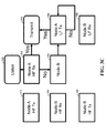
- Figure 3C shows another synchronization approach, as may be implemented with Figure 3A and related components as shown in Figure 3C .
- Node 310's HF transmitter 312, HF receiver 314 and LF transmitter 316 are shown, as are node 320's HF transmitter 322, HF receiver 324 and LF transmitter 326.
- node 310 transmits an LF signal at block 342, and listens at block 340 via HF receiver 314 for an HF response. If a response is detected, node 310 transmits an HF response at block 342. If an HF response is not detected from node 320, the process continues at block 316 with an LF transmission.
- Figure 4 shows an LF+HF apparatus 400, as may be implemented on a remote key side of an automobile access system.
- the apparatus 400 includes circuitry 410 having time-delay processing and round-trip calculation circuitry/block 411, cryptographic unit 412 ( e.g ., including a secure element), memory 413, power circuitry 414 and an LF transmitter and/or receiver 415.
- An HF transmitter/transceiver 420 includes one or more receivers and transmitters.
- the memory 413 includes one or more of RAM, ROM, EROM, or EEPROM.
- the apparatus 400 may include one or more additional components, such as analog-to-digital converters, other processors, baseband and wake-up processing.
- additional components such as analog-to-digital converters, other processors, baseband and wake-up processing.
- a similar approach may be implemented on the base station/automobile side, in which one of the three LF frontends, as shown in LF portion 415, is used.
- PCF7952 datasheet and related circuitry therein as available from NXP Semiconductors of Eindhoven, The Netherlands, which is fully incorporated herein by reference.
- a "block” (also sometimes “logic circuitry” or “module”) is a circuit that carries out one or more of these or related operations/activities (e.g ., transmitter and receiver, memory, synchronization, time delay, memory, and processing).
- one or more modules are discrete logic circuits or programmable logic circuits configured and arranged for implementing these operations/activities, as in the circuit modules shown in Figures 1 and 4 .
- such a programmable circuit is one or more computer circuits programmed to execute a set (or sets) of instructions (and/or configuration data).
- the instructions (and/or configuration data) can be in the form of firmware or software stored in and accessible from a memory (circuit).
- first and second modules include a combination of a CPU hardware-based circuit and a set of instructions in the form of firmware, where the first module includes a first CPU hardware circuit with one set of instructions and the second module includes a second CPU hardware circuit with another set of instructions.
- Certain embodiments are directed to a computer program product (e.g ., nonvolatile memory device), which includes a machine or computer-readable medium having stored thereon instructions which may be executed by a computer (or other electronic device) to perform these operations/activities.
- a computer program product e.g ., nonvolatile memory device
Landscapes
- Engineering & Computer Science (AREA)
- Computer Networks & Wireless Communication (AREA)
- Signal Processing (AREA)
- Computer Security & Cryptography (AREA)
- Mobile Radio Communication Systems (AREA)
- Environmental & Geological Engineering (AREA)
Abstract
Description
- Aspects of various embodiments are directed to communications, and to communications with synchronization.
- Many communication approaches require synchronization and authentication, which have been implemented using a multitude of approaches. For instance, RF ranging systems often employ a time-of-flight principle to determine a distance between two objects, or markers on objects, that are communicating between one another. Proximity can be used from a security and authentication perspective, such as by ensuring that a remote device to be connected to a local device via Bluetooth is within a predetermined threshold distance of the local device (e.g., to prevent unwanted connections to other Bluetooth devices in relative proximity).
- In many applications, a waveform (e.g., a chirp or a pulse) can be transmitted and reflected or retransmitted by an object. Based on the amount of time it takes for the reflection or retransmission to return to the original transmitter, the distance between the objects can be ascertained.
- While various approaches have been implemented for communications in these regards, degradation of the radio signals (e.g., attenuation and reflection) can pose problems. Timing misalignment, interference from other (radio) systems and thermal noise from various sources can also pose problems. With particular regard to timing misalignment, detecting and correcting for such issues can involve an undesirable amount of time and power. For instance, in applications in which packet data is involved, the preamble of the packets can be relatively long compared to the payload, which has an effect on latency and power consumption. These issues can be particularly relevant to certain types of communications, such as in automotive access.
- These and other matters have presented challenges to communications and related aspects such as timing alignment, for a variety of applications.
- Various example embodiments are directed to communication circuits, methods and their implementation.
- According to an example embodiment, communications are effected between a local device and a remote device. The local device has a first clock, a low-frequency (LF) transmitter and a high-frequency (HF) transceiver. The remote device has a second clock, an LF receiver and an HF transceiver. An LF signal is transmitted from the local device to the remote device, and the second clock is synchronized based on the LF signal. A first HF signal is transmitted from the remote device to the local device using the synchronized second clock and a first predetermined time delay relative to receipt of the LF signal at the remote device. The first clock is synchronized based on the first HF signal, and a second HF signal is transmitted from the local device to the remote device using the first clock and a second predetermined time delay relative to receipt of the first HF signal at the local device. The second clock is re-synchronized based on the second HF signal, while accounting for a trip time for at least one of: communicating the first HF signal from the remote device to the local device, and communicating the second HF signal from the local device to the remote device. This approach may be carried out at either the local or remote device, and may be applicable to embodiments involving the local device, the remote device, or both the local and remote devices. Such approaches may, for example, be implemented for minimizing both power consumption and latency overhead due to RF ranging.
- Another embodiment is directed to a method for authenticating a remote device for accessing a local device. A clock is synchronized at the remote device based on an LF signal communicated by the local device. A message is transmitted in a first HF signal from the remote device to the local device, using the synchronized clock and a first predetermined time delay. The local device responds to the first HF signal by synchronizing a clock at the local device based on the first HF signal, and by transmitting the message back to the remote device in a second HF signal using the synchronized clock and a second predetermined time delay. The remote device responds to the second HF signal by re-synchronizing the clock at the remote device, determining a round-trip time for communicating the message from the remote device to the local device and back to the remote device, encrypting the determined round-trip time, and communicating the encrypted round-trip time to the local device. The local device permits the remote device to access data at the local device, based on the encrypted round-trip time.
- In a particular implementation, the clock is synchronized at the remote device as follows. The LF signal is transmitted via an LF transmitter at the local device to an LF receiver at the remote device and an HF transceiver at the remote device is pre-synchronized. A communication link is established between the local and remote devices via an LF polling process including the LF signal. A distance between the local and remote devices is estimated based on the strength of LF signals communicated during the polling process, and an HF transceiver at the local device is pre-synchronized based on the LF polling process and the estimation.
- According to a first aspect, there is provided a method for communicating between a local device having a first clock, a low-frequency (LF) transmitter and a high-frequency (HF) transceiver, and a remote device having a second clock, an LF receiver and an HF transceiver, the method comprising: transmitting an LF signal from the local device to the remote device; at the remote device, synchronizing the second clock based on the LF signal, and transmitting a first HF signal to the local device using the synchronized second clock and a first predetermined time delay relative to receipt of the LF signal at the remote device; at the local device, synchronizing the first clock based on the first HF signal, and transmitting a second HF signal to the remote device using the first clock and a second predetermined time delay relative to receipt of the first HF signal at the local device; and at the remote device, re-synchronizing the second clock based on the second HF signal and while accounting for a trip time for at least one of communicating the first HF signal from the remote device to the local device, and communicating the second HF signal from the local device to the remote device.
- At least one of the local and remote devices may operate using duty-cycled packet detection for packets having a preamble that is longer than a payload of the packet; the local and remote devices may transmit and receive the LF signal respectively using an LF transmitter and an LF receiver; and the local and remote devices may transmit and receive the HF signals using HF transceivers that are respectively separate from the LF transmitter and the LF receiver, thereby minimizing both power consumption and latency overhead due to RF ranging in the communications. Synchronizing the first clock may include synchronizing the first clock based on the first HF signal, the first predetermined time delay, and a time at which the LF signal was transmitted from the local device. Re-synchronizing the second clock based on the second HF signal may include re-synchronizing the second clock based on the second predetermined time delay and a time at which the first HF signal was transmitted. Synchronizing the first clock may include synchronizing the first clock based on the first HF signal, the first predetermined time delay, and a time at which the LF signal was transmitted from the local device, and re-synchronizing the second clock based on the second HF signal may include re-synchronizing the second clock based on the second predetermined time delay and a time at which the first HF signal was transmitted. The method may further include providing authentication for the remote device and access to the local device by the remote device, based on an encrypted estimate of the trip time. Authenticating may include sending a replay message, including an encrypted nonce, based on a message communicated between the local device and the remote device. Transmitting the LF signal may include transmitting the LF signal over an LF channel, and wherein transmitting the HF signals includes transmitting the HF signals over an HF channel that is separate from the LF channel. Re-synchronizing the second clock based on the second HF signal and while accounting for the trip time may include determining, at the remote device, a round-trip time for communicating a message in the first HF signal from the remote device to the local device, and for retransmitting the message in the second HF signal from the local device back to the remote device, thereby providing for correction of timing misalignment between the local and remote devices. The method may further include encrypting the determined round-trip time at the remote device, transmitting the encrypted round-trip time to the local device, and using the encrypted round-trip time for authentication of communications between the local and remote devices.
- The method may further include using a determined round-trip time at both the local device and the remote device, for round-trip times for at least one of: the LF signal and first HF signal, and two HF signals, and using the determined round-trip time in communicating additional data between the local and remote devices. The method may further include repeating the steps of synchronizing the first clock and re-synchronizing the second clock by transmitting a message in respective sets of HF signals between the local and remote devices, calculating the round-trip time for communicating the message in each set from the remote device to the local device and back to the remote device, and re-determining the round-trip time until the accuracy of the determined round-trip time achieves a threshold.
- According to a second aspect, there is provided a method for authenticating a remote device for accessing a local device, the method comprising: synchronizing a clock at the remote device based on an LF signal communicated by the local device; transmitting a message in a first HF signal from the remote device to the local device, using the synchronized clock and a first predetermined time delay; in the local device, responding to the first HF signal by synchronizing a clock at the local device based on the first HF signal, and transmitting the message back to the remote device in a second HF signal using the synchronized clock and a second predetermined time delay; in the remote device, responding to the second HF signal by re-synchronizing the clock at the remote device, determining a round-trip time for communicating the message from the remote device to the local device and back to the remote device, encrypting the determined round-trip time, and communicating the encrypted round-trip time to the local device; and in the local device, providing access to data by the remote device based on the encrypted round-trip time.
- Synchronizing the clock at the remote device may include transmitting the LF signal via an LF transmitter at the local device to an LF receiver at the remote device and pre-synchronizing an HF transceiver at the remote device and may further include: establishing a communication link between the local and remote devices via an LF polling process including the LF signal, estimating a distance between the local and remote devices based on strength of LF signals communicated during the polling process, and pre-synchronizing an HF transceiver at the local device based on the LF polling process and the estimating, thereby minimizing both power consumption and latency overhead due to RF ranging in communications between the local and remote devices.
- Another embodiment is directed to an apparatus for communicating between a local device having a first clock, an LF transmitter and an HF transceiver, and a remote device having a second clock, an LF receiver and an HF transceiver. The apparatus includes an LF communication circuit that communicates an LF signal from the local device to the remote device, and provides synchronization of the second clock at the remote device based on the LF signal. The apparatus also includes an HF communication circuit that operates with the LF communication circuit to provide synchronization as follows. A first HF signal is communicated from the remote device to the local device using the second clock and a first predetermined time delay relative to receipt of the LF signal at the remote device. The first clock is synchronized based on the first HF signal, and a second HF signal is communicated from the local device to the remote device using the first clock and a second predetermined time delay relative to receipt of the first HF signal at the local device. The second clock is resynchronized based on the second HF signal, while accounting for a trip time for at least one of: communicating the first HF signal from the remote device to the local device, and communicating the second HF signal from the local device to the remote device. As consistent with the above, this approach may be implemented with various embodiments, including those directed to the local device, to the remote device, or to both the local and remote devices.
- According to a third aspect, there is provided an apparatus for communicating between a local device having a first clock, a low-frequency (LF) transmitter and a high-frequency (HF) transceiver, and a remote device having a second clock, a LF receiver and a HF transceiver, the apparatus comprising: an LF communication circuit configured and arranged to communicate an LF signal from the local device to the remote device; and provide synchronization of the second clock at the remote device based on the LF signal; and an HF communication circuit configured and arranged with the LF communication circuit to provide synchronization by communicating a first HF signal from the remote device to the local device using the second clock and a first predetermined time delay relative to receipt of the LF signal at the remote device, providing synchronization of the first clock based on the first HF signal, and communicating a second HF signal from the local device to the remote device using the first clock and a second predetermined time delay relative to receipt of the first HF signal at the local device, and providing re-synchronization of the second clock based on the second HF signal and while accounting for a trip time for at least one of communicating the first HF signal from the remote device to the local device, and communicating the second HF signal from the local device to the remote device.
- The LF communication circuit may be the LF receiver in the remote device, and the HF communication circuit may be the HF transceiver in the remote device. The LF communication circuit may be the LF transmitter in the local device, and the HF communication circuit may be the HF transceiver in the local device. The LF communication circuit may include the LF transmitter in the local device and the LF receiver in the remote device, and the HF communication circuit may include the HF transceivers in the local and remote devices. The LF communication circuit may be configured and arranged to communicate the LF signal using duty-cycled packet detection for data in the LF signal, and to provide the synchronization of the second clock by providing synchronization via the LF signal, thereby reducing both power consumption and latency overhead relative to synchronization via the HF signals. The apparatus may further include an authentication circuit configured and arranged to provide authentication for the remote device and access to the local device based on an encrypted estimate of the trip time for communicating a message via the first HF signal from the remote device to the local device, and for communicating the message from the local device back to the remote device via the second HF signal.
- The above discussion/summary is not intended to describe each embodiment or every implementation of the present disclosure. The figures and detailed description that follow also exemplify various embodiments.
- Various example embodiments may be more completely understood in consideration of the following detailed description in connection with the accompanying drawings, in which:
-
FIG. 1 shows a communication apparatus and approach involving synchronization and time-of-flight calculation, as may be implemented in accordance with various embodiments; -
FIG. 2 shows a communication approach and radio packet structure as may be implemented in accordance with one or more embodiments; -
FIG. 3A shows a communication apparatus, in accordance with another example embodiment; -
FIG. 3B shows an example approach to synchronization, as may be implemented withFIG. 3A ; -
FIG. 3C shows another synchronization approach, as may be implemented withFIG. 3A ; and -
FIG. 4 shows a circuit for wireless communication, in accordance with another example embodiment. - While various embodiments discussed herein are amenable to modifications and alternative forms, aspects thereof have been shown by way of example in the drawings and will be described in detail. It should be understood, however, that the intention is not to limit the invention to the particular embodiments described. On the contrary, the intention is to cover all modifications, equivalents, and alternatives falling within the scope of the disclosure including aspects defined in the claims. In addition, the term "example" as used throughout this application is only by way of illustration, and not limitation.
- Aspects of the present disclosure are believed to be applicable to a variety of different types of apparatuses, systems and methods involving data communication and synchronization. While not necessarily so limited, various aspects may be appreciated through a discussion of examples using this context.
- Various example embodiments are directed to reducing acquisition time using side-channel synchronization information, which can be implemented to reduce power requirements for synchronization. Various embodiments are directed to addressing issues relating to this communication. For instance, certain embodiments operate to reduce required on-time by synchronizing two radio nodes over a parallel LF radio link, thereby significantly reducing overall system power consumption. Further embodiments involve communications carried out for data packets in which the preamble includes data that can be used to address frequency, phase and time ambiguities, and/or to facilitate power-saving duty-cycled packet detection, which can be effected before the payload of the packet starts.
- Such approaches are applicable to embodiments in which power consumption is a concern, as is applicable to a variety of radio frequency (RF) ranging (distance) applications, such as those involving short-distance communications for automotive, Bluetooth, near-field communications (NFC), IEEE 802.15.4a, impulse radio ultra-wideband (IR-UWB) applications such as ZigBee (IEEE 802.15), and pulse radars at 60 GHz and higher frequencies. For instance, in IR-UWB RF ranging systems, synchronization requirements may easily dominate on-time requirements over the ranging payload itself.
- According to another example embodiment, communications are effected between a local device and a remote device, each device having a clock and an HF transceiver, with the local device having an LF transmitter and the remote device having an LF receiver. The LF and HF communications may, for example, be carried out using a single channel or separate channels and separate or combined receiver/transmitter/transceiver components. The local device transmits an LF signal to the remote device, which synchronizes its clock based on the LF signal and transmits an HF signal back to the local device using the synchronized clock and a predetermined time delay (e.g., relative to the LF signal). The local device synchronizes its clock using the HF signal, and transmits another HF signal to the remote device using its clock and another predetermined time delay (e.g., relative to receipt of the HF signal). The remote device resynchronizes its clock based on the HF signal transmitted by the local device, while accounting for a trip time for the communication. The trip time may, for example, pertain to communicating the HF signal from the remote device to the local device, communicating the HF signal from the local device to the remote device, or a round-trip time corresponding to both communications. The trip time may, for example, involve communicating an encrypted packet from the remote device to the local device and back to the remote device, with verification provided via the round-trip time and the encryption. Other approaches may involve a trip time for a packet initially communicated by the local device, and retransmitted back to the local device by the remote device.
- The above and other embodiments herein describing communications may be carried out at a local device, at a remote device, or at both the local and remote devices. As such, various embodiments are directed to methods or apparatuses corresponding to one or both of the local and remote devices. Consistent with the above, such embodiments can be implemented for minimizing both power consumption and latency overhead due to RF ranging.
- The above-noted communication approach can be carried out in a variety of systems and with a variety of methods. In a more particular embodiment, one or both of the local and remote devices operates using duty-cycled packet detection for packets having a preamble that is longer than a payload of the packet. The communications may be carried out so as to mitigate issues relating to synchronization requirements of an IR-UWB RF ranging system, in which the synchronization may dominate on-time requirements, such as by reducing power consumption. The local and remote devices transmit and receive the LF signal respectively using an LF transmitter and an LF receiver, and transmit and receive the HF signals using HF transceivers that are respectively separate from the LF transmitter and the LF receiver.
- Synchronization is carried out in a variety of manners, to suit particular embodiments. In some embodiments, the local device clock is synchronized based on the HF signal transmitted by the remote device, together with the first predetermined time delay and a time at which the initial LF signal was transmitted from the local device. In other embodiments, re-synchronizing the clock at the remote device is carried out based on the predetermined time delay implemented at the local device and a time at which the first HF signal was transmitted from the remote device. In certain embodiments, both synchronization and resynchronization are carried out as above.
- In some embodiments, the remote device's clock is resynchronized based on the HF signal transmitted by the local device and a round-trip time as determined for communicating a message in the first HF signal from the remote device to the local device, and for retransmitting the message in the second HF signal from the local device back to the remote device. In some implementations, the round-trip time is encrypted at the remote device, transmitted to the local device, and used for authentication of communications between the local and remote devices. The determined round-trip time may be stored at one or both of the local device and the remote device, and used the in communicating additional data between the devices.
- In a more particular implementation, the steps of synchronizing the local device's clock and re-synchronizing the remote device's clock are repeated. A message is transmitted in respective sets of HF signals communicated between the local and remote devices, and the round-trip time is iteratively determined for communicating the messages until the accuracy of the determined round-trip time achieves a threshold.
- In various embodiments, the communication is carried out using an authentication approach, involving authenticating one or both of the local and remote devices based on an encrypted estimate of the trip time. The authentication can be used for controlling access of the remote device to the local device. In some implementations, the authentication is carried out by sending a replay message, including an encrypted nonce, based on a message communicated between the local device and the remote device.
- Another embodiment is directed to an apparatus for communicating between a local device having a first clock, a low-frequency (LF) transmitter and a high-frequency (HF) transceiver, and a remote device having a second clock, an LF receiver and an HF transceiver. LF and HF communications may, for example, be carried out using a single channel or separate channels, and separate or combined receiver/transmitter/transceiver components. The apparatus includes an LF communication circuit that communicates an LF signal from the local device to the remote device, and provides synchronization of the second clock at the remote device based on the LF signal. The apparatus also includes an HF communication circuit that operates with the LF communication circuit to provide synchronization as follows. A first HF signal is communicated from the remote device to the local device using the second clock and a first predetermined time delay relative to receipt of the LF signal at the remote device. The first clock is synchronized based on the first HF signal, and a second HF signal is communicated from the local device to the remote device using the first clock and a second predetermined time delay relative to receipt of the first HF signal at the local device. The second clock is resynchronized based on the second HF signal, while accounting for a trip time for at least one of: communicating the first HF signal from the remote device to the local device, and communicating the second HF signal from the local device to the remote device. As consistent with the above, this approach may be implemented with various embodiments, including those directed to the local device, to the remote device, or to both the local and remote devices.
- As consistent with the above discussion, various embodiments are directed to a local device, a remote device, or a combination of both. In some embodiments, the apparatus above is directed to the remote device, in which the LF communication circuit is the LF receiver and the HF communication circuit is the HF transceiver. In other embodiments, the apparatus is directed to a local device in which the LF communication circuit is the LF transmitter and the HF communication circuit is the HF transceiver. In certain embodiments directed to both the local and remote devices, the LF communication circuit includes the LF transmitter in the local device and the LF receiver in the remote device, and the HF communication circuit includes the HF transceivers in the local and remote devices.
- Various embodiments are directed to communicating duty-cycled signals, such as in an environment benefiting from low power. In a particular such embodiment, the LF communication circuit communicates the LF signal using duty-cycled packet detection for data in the LF signal, and provides the synchronization of the second clock via the LF signal. With this approach, both power consumption and latency overhead can be reduced, relative to synchronization via the HF signals (e.g., without coarse synchronization with the LF signals).
- Other embodiments involve an authentication circuit that provides authentication for the remote device and access to the local device, based on an encrypted estimate of the trip time for communicating a message via the HF signals. For instance, the round-trip time can be determined from a time at which the first HF signal is transmitted from the remote device, to a time at which the second HF signal is received at the remote device.
- Various embodiments are directed to RF ranging systems that employ a time-of-flight principle to determine a distance between two objects or markers on objects. Time-of-flight is determined by transmitting a waveform, such as a chirp or a pulse, from one of the objects and retransmitting the waveform from the other one of the objects. The distance between the objects can be determined/calculated, and synchronization is carried out based on the transmissions.
- Turning now to the figures,
Figure 1 shows acommunication apparatus 100 and approach involving synchronization and time-of-flight calculation, as may be implemented in accordance with various embodiments, some of which may employ other time-of-flight determination. At alocal device 110, an LF signal is transmitted atblock 112, and the signal is received and processed for clock synchronization and for providing a time delay atblock 122 in aremote device 120. Theremote device 120 transmits a first HF signal atblock 124, based on the synchronization and time delay, with the signal being received atblock 114 of thelocal device 110. Thelocal device 110 uses the first HF signal to carry out synchronization and time delay aspects atblock 114, and transmits a second HF signal atblock 116. Theremote device 120 uses the second HF signal to re-synchronize its clock atblock 126. In this regard, coarse synchronization can be effected via the initial LF signal, and used to facilitate timing alignment via subsequent HF signals. - In a particular time-of-flight implementation, transmitter 130 (e.g., corresponding to
blocks 120/124) sends a time-of-flight challenge signal to receiver 140 (e.g., corresponding toblocks 110/114), and transmitter 142 (e.g., corresponding toblocks 110/116) responds with a time-of-flight response signal that is received by receiver 132 (e.g., corresponding toblocks 120/126). A time-of-flight counter 150 determines time elapsed between transmission of the time-of-flight challenge bytransmitter 130 and reception of the time-of-flight response atreceiver 132.Processing time circuitry 152 provides a fixed or measured processing time delay for signals to be retransmitted. Distance between the devices can then be determined based on the total time, less processing time at the receiver/transmitter 140/142, and any added delay as discussed above. - Such an approach may, for example, be carried out with the transmitter and
receiver local device 110, and thereceiver 140 andtransmitter 142 implemented at theremote device 120, with the time-of-flight pertaining to the initial LF signal and the first HF signal as discussed above. Such an approach may also be carried out in reverse, with the transmitter andreceiver remote device 120, and thereceiver 140 andtransmitter 142 implemented at thelocal device 110, with the time-of-flight pertaining to the transmission of the HF signals. In some implementations, such an approach may be carried out, with time-of-flight being determined at both the local and remote devices, based on LF signals, HF signals or a combination of LF and HF signals. For instance, blocks 112 and 122 can be implemented as LF transceivers, with an additional LF communication going fromblock 122 to block 112. Further iterations of the transmission of HF signals may be carried out to fine tune synchronization. -
Figure 2 shows acommunication approach 200 as may be implemented in accordance with the above-discussed approach inFigure 1 , with similar components at local andremote devices remote devices packet 230 is transmitted with a preamble having coarse carrierfrequency alignment data 232, carrierphase alignment data 234, finetime synchronization data 236, and with apayload 238. In other implementations,packet 240 is transmitted having a preamble with finetime synchronization data 242, and apayload 244. Such approaches may be used in a variety of applications. For instance, in low-latency applications such as for automobile access, synchronization may involve a preamble length that exceeds the length of the payload data, as with eitherpackets - In a particular embodiment, a side-channel can be used (e.g., in the LF communication at
blocks 112 and 122) to provide coarse synchronization and limit the time needed to do fine synchronization for a main (e.g., HF) channel, in the communication of such packets. As such, a two-step approach is used with an LF transmission that provides coarse synchronization for a transceiver that provides accurate RF ranging. The LF transceiver may include a variety of wireless circuits/links such as, for example, 125 kHz magnetic links, 13.56 MHz NFC links, sub-GHz ISM (industrial, scientific and medical) links, Bluetooth enhanced data rate (EDR) or low energy (LE) links, IEEE802.11 links, or 500kHz-15MHz magnetic or (body-centric) capacitive links. In one such implementation, LF circuits establish a link and effect polling that may be desired, and provide a first range estimation based on signal strength. Next, the LF circuits provide timing synchronization and pre-synchronization of HF transceivers that carry out RF ranging, which can minimize unnecessary listening and synchronization-related latency. In this way, both power consumption and latency overhead due to RF ranging link can be reduced or minimized. -
Figure 3A shows acommunication apparatus 300, in accordance with another example embodiment. Thecommunication apparatus 300 includes two communication nodes 310 (depicted as Node A) and 320 (depicted as Node B), which may be implemented as local and remote devices as characterized herein.Node 310 includesHF transmitter 312 andHF receiver 314, which may be combined in an HF transceiver, and anLF transmitter 316.Node 320 includes anHF transmitter 322 andHF receiver 324, which may be combined in an HF transceiver, and anLF receiver 326. In some implementations, theLF transmitter 316 andLF receiver 326 are transceivers, to facilitate bidirectional LF communications between thenodes - In some implementations,
node 310 carries out time-delay processing and round-trip calculation at block 318 as described herein. In other implementations,node 320 carries out such time-delay processing and round-trip calculation atblock 328. In other implementations, bothnodes blocks 318 and 328. This processing and calculation can be carried out using LF communications, HF communications, or a combination of LF and HF communications. - In a particular implementation,
node 310 andnode 320 communicate as follows, such as in using a 125 kHz LF signal and a 4.4 GHz IR-UWB RF HF signal. First, theLF transmitter 316 is enabled, based on a trigger or as part of a polling scheme, and theLF receiver 326 is also enabled (e.g., simultaneously, and temporarily). An LF signal is transmitted fromLF transmitter 316 atnode 310, and theLF receiver 326 atnode 320 detects the LF signal, based on a trigger or as part of a continuous listening scheme. TheLF receiver 326 atnode 320 synchronizes its clock withnode 310 based on the LF signal. - The
HF transmitter 322 atnode 320 is enabled using the same clock that was used to synchronize at LF, and sends an HF signal tonode 310 with a predetermined time delay, relative to an LF packet in the LF signal. TheHF receiver 314 atnode 310 receives HF signal and synchronizes quickly due to the synchronization ofnode 320 to the prior LF signal. - The
HF transmitter 312 is enabled atnode 310, and theHF receiver 324 is enabled atnode 320. TheHF transmitter 312 transmits another HF signal with a predetermined time delay, relative to the HF packet received fromnode 320 via the initial HF signal. TheHF receiver 324 atnode 320 receives HF signal, and synchronizes quickly via the synchronization ofnode 320 to the prior LF signal (and, e.g., the synchronization ofnode 310 to the prior HF signal). Round-trip calculations can be performed atnode 320 and/ornode 310, based on the communications. - In some implementations, multiple similar HF messages are exchanged until
node 320 holds a sufficiently accurate round-trip time estimate. Where multiple messages are sent, the resulting improved round-trip time estimates can also be kept atnode 310. Once the round-trip time estimate is sufficiently accurate, eithernode 320 sends the encrypted estimate back tonode 310, ornode 310 already holds the correct estimate (e.g., from a previous calculation). Ifnode 310 determines thatnode 320 is an intended party (e.g., based on encrypted communications and/or a secure element), and the round-trip time estimate indicates that the distance between the nodes is sufficiently small, access of a user atnode 320 to node 310 (e.g., as an access point) can be permitted/unlocked. In some implementations, the direction of the LF communication as discussed above is reversed with respect to the direction of the RF communication. Further, in someimplementations node 320 is implemented as an access point that provides access tonode 310, with the communications carried out in accordance with the above and verification atnode 320. -
Figure 3B shows an example approach to synchronization as may be implemented withFigure 3A . Atblock 330, a node listens and, if synchronization is to be correlated atblock 331, a response is transmitted atblock 332. If the synchronization is not needed atblock 331, a key match is checked atblock 333. If the key match is correct atblock 333, the process ends atblock 334 with a corresponding transmission atblock 332. If the key match is incorrect atblock 333, the process stops atblock 334. -
Figure 3C shows another synchronization approach, as may be implemented withFigure 3A and related components as shown inFigure 3C .Node 310'sHF transmitter 312,HF receiver 314 andLF transmitter 316 are shown, as arenode 320'sHF transmitter 322,HF receiver 324 andLF transmitter 326. Atblock 316,node 310 transmits an LF signal atblock 342, and listens atblock 340 viaHF receiver 314 for an HF response. If a response is detected,node 310 transmits an HF response atblock 342. If an HF response is not detected fromnode 320, the process continues atblock 316 with an LF transmission. - In various embodiments as shown in
Figures 1-3C , the communications are carried out in devices to various protocols and systems. For example,Figure 4 shows an LF+HF apparatus 400, as may be implemented on a remote key side of an automobile access system. Theapparatus 400 includescircuitry 410 having time-delay processing and round-trip calculation circuitry/block 411, cryptographic unit 412 (e.g., including a secure element),memory 413,power circuitry 414 and an LF transmitter and/orreceiver 415. An HF transmitter/transceiver 420 includes one or more receivers and transmitters. In some embodiments, thememory 413 includes one or more of RAM, ROM, EROM, or EEPROM. Theapparatus 400 may include one or more additional components, such as analog-to-digital converters, other processors, baseband and wake-up processing. A similar approach may be implemented on the base station/automobile side, in which one of the three LF frontends, as shown inLF portion 415, is used. For general information regarding communications, and for specific information regarding immobilizer applications to which one or more embodiments (e.g., as inFigure 4 ) may be applied, reference may be made to the PCF7952 datasheet and related circuitry therein, as available from NXP Semiconductors of Eindhoven, The Netherlands, which is fully incorporated herein by reference. - Various blocks, modules or other circuits may be implemented to carry out one or more of the operations and activities described herein and/or shown in the figures. In these contexts, a "block" (also sometimes "logic circuitry" or "module") is a circuit that carries out one or more of these or related operations/activities (e.g., transmitter and receiver, memory, synchronization, time delay, memory, and processing). For example, in certain of the above-discussed embodiments, one or more modules are discrete logic circuits or programmable logic circuits configured and arranged for implementing these operations/activities, as in the circuit modules shown in
Figures 1 and4 . In certain embodiments, such a programmable circuit is one or more computer circuits programmed to execute a set (or sets) of instructions (and/or configuration data). The instructions (and/or configuration data) can be in the form of firmware or software stored in and accessible from a memory (circuit). As an example, first and second modules include a combination of a CPU hardware-based circuit and a set of instructions in the form of firmware, where the first module includes a first CPU hardware circuit with one set of instructions and the second module includes a second CPU hardware circuit with another set of instructions. - Certain embodiments are directed to a computer program product (e.g., nonvolatile memory device), which includes a machine or computer-readable medium having stored thereon instructions which may be executed by a computer (or other electronic device) to perform these operations/activities.
- Based upon the above discussion and illustrations, those skilled in the art will readily recognize that various modifications and changes may be made to the various embodiments without strictly following the exemplary embodiments and applications illustrated and described herein. For example, certain apparatuses shown in the figures may be separated into embodiments in a single component or node (local/remote device), or combined. Further, certain operations such as synchronization as shown can be carried out in different communication devices, such as by flipping operation of the local and remote devices as described. In addition, the various embodiments described herein may be combined in certain embodiments, and various aspects of individual embodiments may be implemented as separate embodiments. Such modifications do not depart from the true spirit and scope of various aspects of the invention, including aspects set forth in the claims.
Claims (15)
- A method for communicating between a local device having a first clock, a low-frequency (LF) transmitter and a high-frequency (HF) transceiver, and a remote device having a second clock, an LF receiver and an HF transceiver, the method comprising:transmitting an LF signal from the local device to the remote device;at the remote device, synchronizing the second clock based on the LF signal, and transmitting a first HF signal to the local device using the synchronized second clock and a first predetermined time delay relative to receipt of the LF signal at the remote device;at the local device, synchronizing the first clock based on the first HF signal, and transmitting a second HF signal to the remote device using the first clock and a second predetermined time delay relative to receipt of the first HF signal at the local device; andat the remote device, re-synchronizing the second clock based on the second HF signal and while accounting for a trip time for at least one of communicating the first HF signal from the remote device to the local device, and communicating the second HF signal from the local device to the remote device.
- The method of claim 1, wherein
at least one of the local and remote devices operates using duty-cycled packet detection for packets having a preamble that is longer than a payload of the packet;
the local and remote devices transmit and receive the LF signal respectively using an LF transmitter and an LF receiver; and
the local and remote devices transmit and receive the HF signals using HF transceivers that are respectively separate from the LF transmitter and the LF receiver, thereby minimizing both power consumption and latency overhead due to RF ranging in the communications. - The method of claim 1, wherein synchronizing the first clock includes synchronizing the first clock based on the first HF signal, the first predetermined time delay, and a time at which the LF signal was transmitted from the local device.
- The method of claim 1, wherein re-synchronizing the second clock based on the second HF signal includes re-synchronizing the second clock based on the second predetermined time delay and a time at which the first HF signal was transmitted.
- The method of claim 1, wherein
synchronizing the first clock includes synchronizing the first clock based on the first HF signal, the first predetermined time delay, and a time at which the LF signal was transmitted from the local device, and
re-synchronizing the second clock based on the second HF signal includes re-synchronizing the second clock based on the second predetermined time delay and a time at which the first HF signal was transmitted. - The method of claim 1, further including providing authentication for the remote device and access to the local device by the remote device, based on an encrypted estimate of the trip time.
- The method of claim 1, wherein re-synchronizing the second clock based on the second HF signal and while accounting for the trip time includes determining, at the remote device, a round-trip time for communicating a message in the first HF signal from the remote device to the local device, and for retransmitting the message in the second HF signal from the local device back to the remote device, thereby providing for correction of timing misalignment between the local and remote devices.
- The method of claim 7, further including encrypting the determined round-trip time at the remote device, transmitting the encrypted round-trip time to the local device, and using the encrypted round-trip time for authentication of communications between the local and remote devices.
- The method of claim 8, further including
using a determined round-trip time at both the local device and the remote device, for round-trip times for at least one of: the LF signal and first HF signal, and two HF signals, and
using the determined round-trip time in communicating additional data between the local and remote devices. - The method of claim 7, further including repeating the steps of synchronizing the first clock and re-synchronizing the second clock by transmitting a message in respective sets of HF signals between the local and remote devices, calculating the round-trip time for communicating the message in each set from the remote device to the local device and back to the remote device, and re-determining the round-trip time until the accuracy of the determined round-trip time achieves a threshold.
- An apparatus for communicating between a local device having a first clock, a low-frequency (LF) transmitter and a high-frequency (HF) transceiver, and a remote device having a second clock, a LF receiver and a HF transceiver, the apparatus comprising:an LF communication circuit configured and arranged to
communicate an LF signal from the local device to the remote device; and provide synchronization of the second clock at the remote device based on the LF signal; andan HF communication circuit configured and arranged with the LF communication circuit to provide synchronization by
communicating a first HF signal from the remote device to the local device using the second clock and a first predetermined time delay relative to receipt of the LF signal at the remote device,
providing synchronization of the first clock based on the first HF signal, and communicating a second HF signal from the local device to the remote device using the first clock and a second predetermined time delay relative to receipt of the first HF signal at the local device, and
providing re-synchronization of the second clock based on the second HF signal and while accounting for a trip time for at least one of communicating the first HF signal from the remote device to the local device, and communicating the second HF signal from the local device to the remote device. - The apparatus of claim 11, wherein:the LF communication circuit is the LF receiver in the remote device, andthe HF communication circuit is the HF transceiver in the remote device.
- The apparatus of claim 11, wherein:the LF communication circuit is the LF transmitter in the local device, andthe HF communication circuit is the HF transceiver in the local device.
- The apparatus of claim 11, wherein:the LF communication circuit includes the LF transmitter in the local device and the LF receiver in the remote device, andthe HF communication circuit includes the HF transceivers in the local and remote devices.
- The apparatus of claim 11, wherein the LF communication circuit is configured and arranged to communicate the LF signal using duty-cycled packet detection for data in the LF signal, and to provide the synchronization of the second clock by providing synchronization via the LF signal, thereby reducing both power consumption and latency overhead relative to synchronization via the HF signals.
Applications Claiming Priority (1)
| Application Number | Priority Date | Filing Date | Title |
|---|---|---|---|
| US14/468,006 US9160519B1 (en) | 2014-08-25 | 2014-08-25 | Communications with synchronization |
Publications (2)
| Publication Number | Publication Date |
|---|---|
| EP2991416A1 true EP2991416A1 (en) | 2016-03-02 |
| EP2991416B1 EP2991416B1 (en) | 2017-12-13 |
Family
ID=54011570
Family Applications (1)
| Application Number | Title | Priority Date | Filing Date |
|---|---|---|---|
| EP15181949.7A Active EP2991416B1 (en) | 2014-08-25 | 2015-08-21 | Communications with synchronization |
Country Status (2)
| Country | Link |
|---|---|
| US (1) | US9160519B1 (en) |
| EP (1) | EP2991416B1 (en) |
Families Citing this family (7)
| Publication number | Priority date | Publication date | Assignee | Title |
|---|---|---|---|---|
| JP6499018B2 (en) * | 2015-06-05 | 2019-04-10 | 株式会社東芝 | COMMUNICATION DEVICE, COMMUNICATION SYSTEM, ESTIMATION METHOD, AND PROGRAM |
| WO2019110733A1 (en) * | 2017-12-06 | 2019-06-13 | Teade Oü | A self-organizing node and a sensor network with self-organizing nodes |
| EP3570601B1 (en) * | 2018-05-15 | 2023-10-18 | Nxp B.V. | Apparatus and methods for synchronization of transmitters |
| EP3570602B1 (en) | 2018-05-15 | 2021-03-24 | Nxp B.V. | Apparatus and methods for synchronization of transmitters |
| EP3670275A1 (en) * | 2018-12-21 | 2020-06-24 | Nxp B.V. | Rf system and method for implementing role switching of transceiver nodes |
| WO2022123822A1 (en) * | 2020-12-11 | 2022-06-16 | 住友電気工業株式会社 | Smart entry system, central device, smart entry program, and smart entry method |
| US20260040004A1 (en) * | 2024-08-01 | 2026-02-05 | Lenbrook Industries Limited | Systems and methods for synchronizing and rendering audio signals via an auxiliary synchronization back channel |
Citations (2)
| Publication number | Priority date | Publication date | Assignee | Title |
|---|---|---|---|---|
| WO2001003344A1 (en) * | 1999-01-15 | 2001-01-11 | Airbiquity Inc. | In-band signalling for synchronization in a voice communications network |
| EP1215559A2 (en) * | 2000-12-13 | 2002-06-19 | Chrysalis- ITS Inc. | Method and system for time synchronization |
Family Cites Families (6)
| Publication number | Priority date | Publication date | Assignee | Title |
|---|---|---|---|---|
| US6618456B1 (en) * | 1999-10-21 | 2003-09-09 | Semtech Corporation | Asynchronous timing oscillator re-synchronizer and method |
| US7444118B2 (en) | 2003-04-29 | 2008-10-28 | Nxp B.V. | Electronic communications system |
| WO2009044365A2 (en) | 2007-10-03 | 2009-04-09 | Nxp B.V. | Method and system for impulse radio wakeup |
| US8493192B2 (en) | 2010-11-01 | 2013-07-23 | Nxp B.V. | Immobilizer circuit |
| US8826062B2 (en) * | 2011-05-23 | 2014-09-02 | Intel Mobile Communications GmbH | Apparatus for synchronizing a data handover between a first clock domain and a second clock domain through phase synchronization |
| US9048681B2 (en) | 2012-02-22 | 2015-06-02 | Nxp B.V. | Wireless power and data apparatus, system and method |
-
2014
- 2014-08-25 US US14/468,006 patent/US9160519B1/en active Active
-
2015
- 2015-08-21 EP EP15181949.7A patent/EP2991416B1/en active Active
Patent Citations (2)
| Publication number | Priority date | Publication date | Assignee | Title |
|---|---|---|---|---|
| WO2001003344A1 (en) * | 1999-01-15 | 2001-01-11 | Airbiquity Inc. | In-band signalling for synchronization in a voice communications network |
| EP1215559A2 (en) * | 2000-12-13 | 2002-06-19 | Chrysalis- ITS Inc. | Method and system for time synchronization |
Also Published As
| Publication number | Publication date |
|---|---|
| EP2991416B1 (en) | 2017-12-13 |
| US9160519B1 (en) | 2015-10-13 |
Similar Documents
| Publication | Publication Date | Title |
|---|---|---|
| EP2991416B1 (en) | Communications with synchronization | |
| JP7385568B2 (en) | Ranging with simultaneous frames | |
| EP3054315B1 (en) | Pulse frequency control for wireless communications and ranging | |
| CN112313974A (en) | Ultra-wideband based vehicle access system and communication protocol for target device location | |
| US9602270B2 (en) | Clock drift compensation in a time synchronous channel hopping network | |
| US10779118B2 (en) | Media access control (MAC) frame structure and data communication method in a real-time localization system | |
| US10237836B2 (en) | Frequency and phase synchronization using full duplex radios over wireless mesh networks | |
| CN108696405B (en) | Range determination module and related methods and apparatus | |
| US10341865B2 (en) | Distance estimation and authentication for Bluetooth systems, and devices | |
| CN108512792B (en) | Device for radio apparatus | |
| CN114646922A (en) | Optimized secure phase-based positioning | |
| US11728943B2 (en) | Methods and apparatuses for communicating position reference signals | |
| EP2991251B1 (en) | Communication synchronization | |
| US12610231B2 (en) | Wireless fine time measurement authentication | |
| US20240385309A1 (en) | Method and system for ultra-wideband two-way ranging | |
| EP4095553A1 (en) | Method for transceiving a message for uwb distance measurement, method and system for distance measurement and transceiver for uwb distance measurement | |
| EP4386441A1 (en) | Distance assessment with headerless packets | |
| US12137427B2 (en) | Method and apparatus for simple time synchronization of a communication in industrial settings | |
| WO2019170256A1 (en) | Techniques for time reference distribution | |
| CN101098185A (en) | Method of Frame Synchronization in Mobile Communication System | |
| KR100895443B1 (en) | System and method for transmitting and receiving data in frequency division multiplexing | |
| Nguyen et al. | Time synchronisation with improved accuracy for TDMA-based wireless sensor networks | |
| WO2017117671A1 (en) | Range determination without prior synchronization between transceivers | |
| TW201640858A (en) | Synchronization source device for synchronization coverage extension and method and system using the same |
Legal Events
| Date | Code | Title | Description |
|---|---|---|---|
| PUAI | Public reference made under article 153(3) epc to a published international application that has entered the european phase |
Free format text: ORIGINAL CODE: 0009012 |
|
| AK | Designated contracting states |
Kind code of ref document: A1 Designated state(s): AL AT BE BG CH CY CZ DE DK EE ES FI FR GB GR HR HU IE IS IT LI LT LU LV MC MK MT NL NO PL PT RO RS SE SI SK SM TR |
|
| AX | Request for extension of the european patent |
Extension state: BA ME |
|
| 17P | Request for examination filed |
Effective date: 20160902 |
|
| RBV | Designated contracting states (corrected) |
Designated state(s): AL AT BE BG CH CY CZ DE DK EE ES FI FR GB GR HR HU IE IS IT LI LT LU LV MC MK MT NL NO PL PT RO RS SE SI SK SM TR |
|
| GRAP | Despatch of communication of intention to grant a patent |
Free format text: ORIGINAL CODE: EPIDOSNIGR1 |
|
| RIC1 | Information provided on ipc code assigned before grant |
Ipc: H04W 4/00 20090101ALI20170707BHEP Ipc: H04W 56/00 20090101AFI20170707BHEP Ipc: H04W 12/06 20090101ALI20170707BHEP Ipc: H04L 12/26 20060101ALN20170707BHEP Ipc: H04W 4/02 20090101ALN20170707BHEP Ipc: H04J 3/06 20060101ALN20170707BHEP |
|
| INTG | Intention to grant announced |
Effective date: 20170725 |
|
| GRAS | Grant fee paid |
Free format text: ORIGINAL CODE: EPIDOSNIGR3 |
|
| GRAA | (expected) grant |
Free format text: ORIGINAL CODE: 0009210 |
|
| REG | Reference to a national code |
Ref country code: GB Ref legal event code: FG4D |
|
| REG | Reference to a national code |
Ref country code: AT Ref legal event code: REF Ref document number: 955445 Country of ref document: AT Kind code of ref document: T Effective date: 20171215 Ref country code: CH Ref legal event code: EP |
|
| REG | Reference to a national code |
Ref country code: IE Ref legal event code: FG4D |
|
| REG | Reference to a national code |
Ref country code: DE Ref legal event code: R096 Ref document number: 602015006595 Country of ref document: DE |
|
| REG | Reference to a national code |
Ref country code: NL Ref legal event code: MP Effective date: 20171213 |
|
| PG25 | Lapsed in a contracting state [announced via postgrant information from national office to epo] |
Ref country code: NO Free format text: LAPSE BECAUSE OF FAILURE TO SUBMIT A TRANSLATION OF THE DESCRIPTION OR TO PAY THE FEE WITHIN THE PRESCRIBED TIME-LIMIT Effective date: 20180313 Ref country code: SE Free format text: LAPSE BECAUSE OF FAILURE TO SUBMIT A TRANSLATION OF THE DESCRIPTION OR TO PAY THE FEE WITHIN THE PRESCRIBED TIME-LIMIT Effective date: 20171213 Ref country code: FI Free format text: LAPSE BECAUSE OF FAILURE TO SUBMIT A TRANSLATION OF THE DESCRIPTION OR TO PAY THE FEE WITHIN THE PRESCRIBED TIME-LIMIT Effective date: 20171213 |
|
| REG | Reference to a national code |
Ref country code: AT Ref legal event code: MK05 Ref document number: 955445 Country of ref document: AT Kind code of ref document: T Effective date: 20171213 |
|
| PG25 | Lapsed in a contracting state [announced via postgrant information from national office to epo] |
Ref country code: GR Free format text: LAPSE BECAUSE OF FAILURE TO SUBMIT A TRANSLATION OF THE DESCRIPTION OR TO PAY THE FEE WITHIN THE PRESCRIBED TIME-LIMIT Effective date: 20180314 Ref country code: RS Free format text: LAPSE BECAUSE OF FAILURE TO SUBMIT A TRANSLATION OF THE DESCRIPTION OR TO PAY THE FEE WITHIN THE PRESCRIBED TIME-LIMIT Effective date: 20171213 Ref country code: BG Free format text: LAPSE BECAUSE OF FAILURE TO SUBMIT A TRANSLATION OF THE DESCRIPTION OR TO PAY THE FEE WITHIN THE PRESCRIBED TIME-LIMIT Effective date: 20180313 Ref country code: HR Free format text: LAPSE BECAUSE OF FAILURE TO SUBMIT A TRANSLATION OF THE DESCRIPTION OR TO PAY THE FEE WITHIN THE PRESCRIBED TIME-LIMIT Effective date: 20171213 Ref country code: LV Free format text: LAPSE BECAUSE OF FAILURE TO SUBMIT A TRANSLATION OF THE DESCRIPTION OR TO PAY THE FEE WITHIN THE PRESCRIBED TIME-LIMIT Effective date: 20171213 |
|
| PG25 | Lapsed in a contracting state [announced via postgrant information from national office to epo] |
Ref country code: NL Free format text: LAPSE BECAUSE OF FAILURE TO SUBMIT A TRANSLATION OF THE DESCRIPTION OR TO PAY THE FEE WITHIN THE PRESCRIBED TIME-LIMIT Effective date: 20171213 |
|
| REG | Reference to a national code |
Ref country code: FR Ref legal event code: PLFP Year of fee payment: 4 |
|
| PG25 | Lapsed in a contracting state [announced via postgrant information from national office to epo] |
Ref country code: CZ Free format text: LAPSE BECAUSE OF FAILURE TO SUBMIT A TRANSLATION OF THE DESCRIPTION OR TO PAY THE FEE WITHIN THE PRESCRIBED TIME-LIMIT Effective date: 20171213 Ref country code: SK Free format text: LAPSE BECAUSE OF FAILURE TO SUBMIT A TRANSLATION OF THE DESCRIPTION OR TO PAY THE FEE WITHIN THE PRESCRIBED TIME-LIMIT Effective date: 20171213 Ref country code: EE Free format text: LAPSE BECAUSE OF FAILURE TO SUBMIT A TRANSLATION OF THE DESCRIPTION OR TO PAY THE FEE WITHIN THE PRESCRIBED TIME-LIMIT Effective date: 20171213 Ref country code: ES Free format text: LAPSE BECAUSE OF FAILURE TO SUBMIT A TRANSLATION OF THE DESCRIPTION OR TO PAY THE FEE WITHIN THE PRESCRIBED TIME-LIMIT Effective date: 20171213 Ref country code: CY Free format text: LAPSE BECAUSE OF FAILURE TO SUBMIT A TRANSLATION OF THE DESCRIPTION OR TO PAY THE FEE WITHIN THE PRESCRIBED TIME-LIMIT Effective date: 20171213 |
|
| PG25 | Lapsed in a contracting state [announced via postgrant information from national office to epo] |
Ref country code: IT Free format text: LAPSE BECAUSE OF FAILURE TO SUBMIT A TRANSLATION OF THE DESCRIPTION OR TO PAY THE FEE WITHIN THE PRESCRIBED TIME-LIMIT Effective date: 20171213 Ref country code: RO Free format text: LAPSE BECAUSE OF FAILURE TO SUBMIT A TRANSLATION OF THE DESCRIPTION OR TO PAY THE FEE WITHIN THE PRESCRIBED TIME-LIMIT Effective date: 20171213 Ref country code: AT Free format text: LAPSE BECAUSE OF FAILURE TO SUBMIT A TRANSLATION OF THE DESCRIPTION OR TO PAY THE FEE WITHIN THE PRESCRIBED TIME-LIMIT Effective date: 20171213 Ref country code: PL Free format text: LAPSE BECAUSE OF FAILURE TO SUBMIT A TRANSLATION OF THE DESCRIPTION OR TO PAY THE FEE WITHIN THE PRESCRIBED TIME-LIMIT Effective date: 20171213 Ref country code: SM Free format text: LAPSE BECAUSE OF FAILURE TO SUBMIT A TRANSLATION OF THE DESCRIPTION OR TO PAY THE FEE WITHIN THE PRESCRIBED TIME-LIMIT Effective date: 20171213 Ref country code: IS Free format text: LAPSE BECAUSE OF FAILURE TO SUBMIT A TRANSLATION OF THE DESCRIPTION OR TO PAY THE FEE WITHIN THE PRESCRIBED TIME-LIMIT Effective date: 20180413 |
|
| REG | Reference to a national code |
Ref country code: DE Ref legal event code: R097 Ref document number: 602015006595 Country of ref document: DE |
|
| PLBE | No opposition filed within time limit |
Free format text: ORIGINAL CODE: 0009261 |
|
| STAA | Information on the status of an ep patent application or granted ep patent |
Free format text: STATUS: NO OPPOSITION FILED WITHIN TIME LIMIT |
|
| 26N | No opposition filed |
Effective date: 20180914 |
|
| PG25 | Lapsed in a contracting state [announced via postgrant information from national office to epo] |
Ref country code: DK Free format text: LAPSE BECAUSE OF FAILURE TO SUBMIT A TRANSLATION OF THE DESCRIPTION OR TO PAY THE FEE WITHIN THE PRESCRIBED TIME-LIMIT Effective date: 20171213 |
|
| PG25 | Lapsed in a contracting state [announced via postgrant information from national office to epo] |
Ref country code: SI Free format text: LAPSE BECAUSE OF FAILURE TO SUBMIT A TRANSLATION OF THE DESCRIPTION OR TO PAY THE FEE WITHIN THE PRESCRIBED TIME-LIMIT Effective date: 20171213 |
|
| PG25 | Lapsed in a contracting state [announced via postgrant information from national office to epo] |
Ref country code: MC Free format text: LAPSE BECAUSE OF FAILURE TO SUBMIT A TRANSLATION OF THE DESCRIPTION OR TO PAY THE FEE WITHIN THE PRESCRIBED TIME-LIMIT Effective date: 20171213 |
|
| REG | Reference to a national code |
Ref country code: CH Ref legal event code: PL |
|
| PG25 | Lapsed in a contracting state [announced via postgrant information from national office to epo] |
Ref country code: LI Free format text: LAPSE BECAUSE OF NON-PAYMENT OF DUE FEES Effective date: 20180831 Ref country code: CH Free format text: LAPSE BECAUSE OF NON-PAYMENT OF DUE FEES Effective date: 20180831 Ref country code: LU Free format text: LAPSE BECAUSE OF NON-PAYMENT OF DUE FEES Effective date: 20180821 |
|
| REG | Reference to a national code |
Ref country code: BE Ref legal event code: MM Effective date: 20180831 |
|
| PG25 | Lapsed in a contracting state [announced via postgrant information from national office to epo] |
Ref country code: BE Free format text: LAPSE BECAUSE OF NON-PAYMENT OF DUE FEES Effective date: 20180831 |
|
| PG25 | Lapsed in a contracting state [announced via postgrant information from national office to epo] |
Ref country code: MT Free format text: LAPSE BECAUSE OF NON-PAYMENT OF DUE FEES Effective date: 20180821 |
|
| PG25 | Lapsed in a contracting state [announced via postgrant information from national office to epo] |
Ref country code: TR Free format text: LAPSE BECAUSE OF FAILURE TO SUBMIT A TRANSLATION OF THE DESCRIPTION OR TO PAY THE FEE WITHIN THE PRESCRIBED TIME-LIMIT Effective date: 20171213 |
|
| GBPC | Gb: european patent ceased through non-payment of renewal fee |
Effective date: 20190821 |
|
| PG25 | Lapsed in a contracting state [announced via postgrant information from national office to epo] |
Ref country code: PT Free format text: LAPSE BECAUSE OF FAILURE TO SUBMIT A TRANSLATION OF THE DESCRIPTION OR TO PAY THE FEE WITHIN THE PRESCRIBED TIME-LIMIT Effective date: 20171213 |
|
| PG25 | Lapsed in a contracting state [announced via postgrant information from national office to epo] |
Ref country code: HU Free format text: LAPSE BECAUSE OF FAILURE TO SUBMIT A TRANSLATION OF THE DESCRIPTION OR TO PAY THE FEE WITHIN THE PRESCRIBED TIME-LIMIT; INVALID AB INITIO Effective date: 20150821 Ref country code: LT Free format text: LAPSE BECAUSE OF FAILURE TO SUBMIT A TRANSLATION OF THE DESCRIPTION OR TO PAY THE FEE WITHIN THE PRESCRIBED TIME-LIMIT Effective date: 20171213 Ref country code: MK Free format text: LAPSE BECAUSE OF NON-PAYMENT OF DUE FEES Effective date: 20171213 Ref country code: IE Free format text: LAPSE BECAUSE OF NON-PAYMENT OF DUE FEES Effective date: 20180821 |
|
| PG25 | Lapsed in a contracting state [announced via postgrant information from national office to epo] |
Ref country code: AL Free format text: LAPSE BECAUSE OF FAILURE TO SUBMIT A TRANSLATION OF THE DESCRIPTION OR TO PAY THE FEE WITHIN THE PRESCRIBED TIME-LIMIT Effective date: 20171213 |
|
| PG25 | Lapsed in a contracting state [announced via postgrant information from national office to epo] |
Ref country code: GB Free format text: LAPSE BECAUSE OF NON-PAYMENT OF DUE FEES Effective date: 20190821 |
|
| P01 | Opt-out of the competence of the unified patent court (upc) registered |
Effective date: 20230725 |
|
| PGFP | Annual fee paid to national office [announced via postgrant information from national office to epo] |
Ref country code: DE Payment date: 20250724 Year of fee payment: 11 |
|
| PGFP | Annual fee paid to national office [announced via postgrant information from national office to epo] |
Ref country code: FR Payment date: 20250723 Year of fee payment: 11 |