EP2991377A1 - Acoustic apparatus - Google Patents
Acoustic apparatus Download PDFInfo
- Publication number
- EP2991377A1 EP2991377A1 EP14788772.3A EP14788772A EP2991377A1 EP 2991377 A1 EP2991377 A1 EP 2991377A1 EP 14788772 A EP14788772 A EP 14788772A EP 2991377 A1 EP2991377 A1 EP 2991377A1
- Authority
- EP
- European Patent Office
- Prior art keywords
- panel
- sound
- user
- acoustic device
- ear
- Prior art date
- Legal status (The legal status is an assumption and is not a legal conclusion. Google has not performed a legal analysis and makes no representation as to the accuracy of the status listed.)
- Granted
Links
Images




Classifications
-
- H—ELECTRICITY
- H04—ELECTRIC COMMUNICATION TECHNIQUE
- H04R—LOUDSPEAKERS, MICROPHONES, GRAMOPHONE PICK-UPS OR LIKE ACOUSTIC ELECTROMECHANICAL TRANSDUCERS; ELECTRIC HEARING AIDS; PUBLIC ADDRESS SYSTEMS
- H04R25/00—Electric hearing aids
- H04R25/60—Mounting or interconnection of hearing aid parts, e.g. inside tips, housings or to ossicles
- H04R25/604—Mounting or interconnection of hearing aid parts, e.g. inside tips, housings or to ossicles of acoustic or vibrational transducers
-
- H—ELECTRICITY
- H04—ELECTRIC COMMUNICATION TECHNIQUE
- H04R—LOUDSPEAKERS, MICROPHONES, GRAMOPHONE PICK-UPS OR LIKE ACOUSTIC ELECTROMECHANICAL TRANSDUCERS; ELECTRIC HEARING AIDS; PUBLIC ADDRESS SYSTEMS
- H04R17/00—Piezoelectric transducers; Electrostrictive transducers
-
- H—ELECTRICITY
- H04—ELECTRIC COMMUNICATION TECHNIQUE
- H04R—LOUDSPEAKERS, MICROPHONES, GRAMOPHONE PICK-UPS OR LIKE ACOUSTIC ELECTROMECHANICAL TRANSDUCERS; ELECTRIC HEARING AIDS; PUBLIC ADDRESS SYSTEMS
- H04R25/00—Electric hearing aids
-
- H—ELECTRICITY
- H04—ELECTRIC COMMUNICATION TECHNIQUE
- H04R—LOUDSPEAKERS, MICROPHONES, GRAMOPHONE PICK-UPS OR LIKE ACOUSTIC ELECTROMECHANICAL TRANSDUCERS; ELECTRIC HEARING AIDS; PUBLIC ADDRESS SYSTEMS
- H04R25/00—Electric hearing aids
- H04R25/02—Electric hearing aids adapted to be supported entirely by ear
-
- H—ELECTRICITY
- H04—ELECTRIC COMMUNICATION TECHNIQUE
- H04R—LOUDSPEAKERS, MICROPHONES, GRAMOPHONE PICK-UPS OR LIKE ACOUSTIC ELECTROMECHANICAL TRANSDUCERS; ELECTRIC HEARING AIDS; PUBLIC ADDRESS SYSTEMS
- H04R25/00—Electric hearing aids
- H04R25/48—Electric hearing aids using constructional means for obtaining a desired frequency response
-
- H—ELECTRICITY
- H04—ELECTRIC COMMUNICATION TECHNIQUE
- H04R—LOUDSPEAKERS, MICROPHONES, GRAMOPHONE PICK-UPS OR LIKE ACOUSTIC ELECTROMECHANICAL TRANSDUCERS; ELECTRIC HEARING AIDS; PUBLIC ADDRESS SYSTEMS
- H04R2217/00—Details of magnetostrictive, piezoelectric, or electrostrictive transducers covered by H04R15/00 or H04R17/00 but not provided for in any of their subgroups
- H04R2217/01—Non-planar magnetostrictive, piezoelectric or electrostrictive benders
-
- H—ELECTRICITY
- H04—ELECTRIC COMMUNICATION TECHNIQUE
- H04R—LOUDSPEAKERS, MICROPHONES, GRAMOPHONE PICK-UPS OR LIKE ACOUSTIC ELECTROMECHANICAL TRANSDUCERS; ELECTRIC HEARING AIDS; PUBLIC ADDRESS SYSTEMS
- H04R2460/00—Details of hearing devices, i.e. of ear- or headphones covered by H04R1/10 or H04R5/033 but not provided for in any of their subgroups, or of hearing aids covered by H04R25/00 but not provided for in any of its subgroups
- H04R2460/09—Non-occlusive ear tips, i.e. leaving the ear canal open, for both custom and non-custom tips
-
- H—ELECTRICITY
- H04—ELECTRIC COMMUNICATION TECHNIQUE
- H04R—LOUDSPEAKERS, MICROPHONES, GRAMOPHONE PICK-UPS OR LIKE ACOUSTIC ELECTROMECHANICAL TRANSDUCERS; ELECTRIC HEARING AIDS; PUBLIC ADDRESS SYSTEMS
- H04R2460/00—Details of hearing devices, i.e. of ear- or headphones covered by H04R1/10 or H04R5/033 but not provided for in any of their subgroups, or of hearing aids covered by H04R25/00 but not provided for in any of its subgroups
- H04R2460/13—Hearing devices using bone conduction transducers
Definitions
- This disclosure relates to an acoustic device, such as a hearing aid.
- a vent connecting the inside of the external ear canal to the outside is provided to alleviate an occlusion effect when wearing the hearing aid (for example, see JP 2006-304147 A (PTL 1)).
- This type of hearing aid includes a microphone, an earphone, and a vent.
- the microphone collects sound from a sound source, and the earphone causes the user to hear the sound collected by the microphone.
- the vent is a hole connecting the inside of the external ear canal to the outside, as described above. As a result of the vent, the external ear canal is not completely sealed. Therefore, the occlusion effect that occurs when wearing the hearing aid is alleviated.
- an acoustic device for causing a user to hear sound includes:
- the concavity in the panel may contact the user's tragus from outside the user's ear and transmit vibration of the panel to the tragus.
- the concavity in the panel may contact the user's antitragus from outside the user's ear and transmit vibration of the panel to the antitragus.
- a principal surface of the panel may include a portion that contacts the ear and a portion that does not contact the ear.
- the acoustic device may be configured not to completely seal the user's external ear canal.
- the panel may vibrate with an antinode at a central region of the panel and a node on both sides of the antinode, and a location at the central region of the panel may contact the tragus.
- the panel may vibrate with an antinode at a central region of the panel and a node on both sides of the antinode, and a location at the central region of the panel may contact the antitragus.
- the sound-collecting acoustic device may further include a microphone.
- the vibration unit may generate an external ear canal radiated sound inside the user's ear.
- the vibration unit may be pressed against the user's ear with a force of 0.1 N to 3 N.
- the piezoelectric element may be plate-shaped, and the panel may have an area between 0.8 and 10 times an area of a principal surface of the piezoelectric element.
- This acoustic device can suppress a loss in sense of volume and sense of comfort.
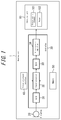
- FIG. 1 is a block diagram of an acoustic device 1 according to one of the disclosed embodiments.
- the acoustic device 1 is, for example, a hearing aid 1 and includes a vibration unit 10, a microphone 20, a controller 30, an adjustment interface 40, and a memory 50.
- the vibration unit 10 includes a piezoelectric element 101 that flexes and a panel 102 that vibrates by being bent directly by the piezoelectric element 101.
- FIG. 2 schematically illustrates flexing of the panel 102 due to the piezoelectric element 101.
- the vibration unit 10 causes the user to hear air-conducted sound and human body vibration sound due to vibration.
- Air-conducted sound is sound transmitted to the user's auditory nerve by air vibrations, caused by a vibrating object, that are transmitted through the external ear canal to the eardrum and cause the eardrum to vibrate.
- Human body vibration sound is sound that is transmitted to the user's auditory nerve through a portion of the user's body (such as the cartilage of the outer ear) that is contacting a vibrating object.
- the piezoelectric element 101 is formed by elements that, upon application of an electric signal (voltage), either expand and contract or bend (flex) in accordance with the electromechanical coupling coefficient of their constituent material. Ceramic or crystal elements, for example, may be used.
- the piezoelectric element 101 may be a unimorph, bimorph, or laminated piezoelectric element. Examples of a laminated piezoelectric element include a laminated unimorph element with layers of unimorph (for example, 16 or 24 layers) and a laminated bimorph element with layers of bimorph (for example, 16 or 24 layers).
- Such a laminated piezoelectric element may be configured with a laminated structure formed by a plurality of dielectric layers composed of, for example, lead zirconate titanate (PZT) and electrode layers disposed between the dielectric layers.
- PZT lead zirconate titanate
- Unimorph expands and contracts upon the application of an electric signal (voltage), and bimorph bends upon the application of an electric signal (voltage).
- the panel 102 is, for example, made from glass or a synthetic resin such as acrylic or the like.
- An exemplary shape of the panel 102 is a plate, and the shape of the panel 102 is described below as being a plate.
- the microphone 20 collects sound from a sound source, namely sound reaching the user's ear.
- the controller 30 executes various control pertaining to the hearing aid 1.
- the controller 30 applies a predetermined electric signal (a voltage corresponding to a sound signal) to the piezoelectric element 101.
- a predetermined electric signal a voltage corresponding to a sound signal
- an A/D converter 31 converts a sound signal collected by the microphone 20 into a digital signal.
- a signal processor 32 Based on information on volume, sound quality, and the like from the adjustment interface 40 for volume and sound quality and on information stored in the memory 50, a signal processor 32 outputs a digital signal that drives the vibration unit 10.
- a D/A converter 33 converts the digital signal to an analog electric signal, which is then amplified by a piezoelectric amplifier 34. The resulting electric signal is applied to the piezoelectric element 101.
- the voltage that the controller 30 applies to the piezoelectric element 101 may, for example, be ⁇ 15 V. This is higher than ⁇ 5 V, i.e. the applied voltage of a so-called panel speaker for conduction of sound by air-conducted sound rather than human body vibration sound. In this way, sufficient vibration is generated in the panel 102, so that a human body vibration sound can be generated via a part of the user's body.
- the magnitude of the applied voltage used may be appropriately adjusted in accordance with the fixation strength of the panel 102 or the performance of the piezoelectric element 101.
- the panel 102 to which the piezoelectric element 101 is attached vibrates by deforming in conjunction with the expansion and contraction or bending of the piezoelectric element 101.
- the panel 102 flexes due to expansion and contraction or to bending of the piezoelectric element 101.
- the panel 102 is bent directly by the piezoelectric element 101.
- Stating that "the panel 102 is bent directly by the piezoelectric element 101" differs from the phenomenon utilized in known panel speakers, whereby the panel 102 deforms upon vibration of a particular region of the panel 102 due to the inertial force of a piezoelectric actuator constituted by disposing the piezoelectric element 101 in the casing.
- Stating that "the panel 102 is bent directly by the piezoelectric element 101” refers instead to how expansion and contraction or bending (flexure) of the piezoelectric element 101 directly bends the panel 102 via the joining member.
- the panel 102 vibrates as described above, the panel 102 generates air-conducted sound, and when the user contacts the panel 102 to the tragus, the panel 102 generates human body vibration sound via the tragus.
- the panel 102 preferably vibrates with locations near the edges of the panel 102 as nodes and the central region as an antinode, and a location at the central region of the panel 102 preferably contacts the tragus or antitragus. As a result, vibration of the panel 102 can be efficiently transmitted to the tragus or the antitragus.
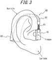
- FIG. 3 schematically illustrates the structure of the hearing aid 1 according to one of the disclosed embodiments.
- the vibration unit 10 is contacted to the user's tragus from outside the user's ear. Therefore, a holder 60 is provided.
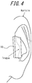
- FIG. 4 illustrates the vibration unit 10 in contact with the tragus.
- the vibration unit 10 contacts the protruding tragus, and therefore by providing the below-described concavity 104 at the position of contact with the tragus, the area of contact between the vibration unit 10 and the tragus can be sufficiently insured without crushing the tragus.
- the position of contact with the user's ear is the tragus.
- the holder 60 includes a support 61, an ear hook 62, and a body 63.
- the holder 60 holds the vibration unit 10 at the position at which the vibration unit 10 contacts the user's ear (at the tragus).
- One end of the support 61 is connected to the vibration unit 10.
- the support 61 has a hollow structure, and a lead wire is fed to the vibration unit 10 through this hollow structure.
- the support 61 is rigid enough so that the angle of the vibration unit 10 does not change.
- the other end of the support 61 is connected to one end of the ear hook 62.
- the ear hook 62 contacts the outside of the user's auricle to mount the hearing aid 1 in the user's ear.
- the ear hook 62 is preferably shaped as a hook conforming to the user's auricle so as to mount the hearing aid 1 stably in the user's ear.
- the other end of the ear hook 62 is connected to the body 63.
- the body 63 stores the microphone 20, controller 30, adjustment interface 40, and memory 50 therein.
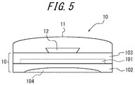
- FIG. 5 is a side view of the vibration unit 10 as viewed in the thickness direction.
- the vibration unit 10 includes the piezoelectric element 101 and the panel 102.
- the piezoelectric element 101 is preferably shaped as a plate, as in FIG. 5 .
- the piezoelectric element 101 is joined to the panel 102 by a joining member.
- the joining member is disposed between the principal surface of the piezoelectric element 101 and the principal surface of the panel 102.
- the joining member is preferably a non-heat hardening adhesive material or double-sided tape. Apart from the surface joined to the panel 102, the piezoelectric element 101 is covered by a mold 103.
- the principle surface of the panel 102 includes the concavity 104.
- the concavity 104 is a recessed portion in the central region of the panel 102. Since the tragus projects outward, it is necessary to secure the area of contact by crushing the tragus when contacting a flat surface thereto. Conversely, since the hearing aid 1 includes the concavity 104, and this concavity 104 contacts the tragus, the area of contact can be secured without crushing the tragus. Since it is not necessary to crush the tragus, the holder 60 can have a simple structure. Furthermore, since the tragus is not crushed, a sense of comfort can be maintained when the user wears the hearing aid 1.
- the panel 102 of the vibration unit 10 is pressed against the user's ear with a force of 0.1 N to 3 N. If the panel 102 is pressed with a force between 0.1 N and 3 N, vibration by the panel 102 is sufficiently transmitted to the ear. Furthermore, if the pressure is a small force of less than 3 N, the user suffers little fatigue even when wearing the hearing aid 1 for an extended period of time, thus maintaining a sense of comfort when wearing the hearing aid 1.
- the concavity 104 of the panel 102 preferably includes a portion that contacts the user's ear (for example, the tragus) and a portion that does not contact the user's ear. By providing a portion that does not contact the user's ear within the panel 102, it may be possible to generate air-conducted sound from this portion.
- the principal surface of the panel 102 preferably has an area between 0.8 and 10 times the area of the principal surface of the piezoelectric element 101. If the principal surface of the panel 102 has an area between 0.8 and 10 times the area of the principal surface of the piezoelectric element 101, the panel 102 can deform in conjunction with expansion and contraction or bending of the piezoelectric element 101, and the area of contact with the user's ear can be sufficiently guaranteed.
- the area of the panel is, for example, more preferably between 0.8 and 5 times the area of the piezoelectric element.
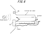
- FIG. 6 schematically illustrates transmission of sound from the hearing aid 1 according to one of the disclosed embodiments.
- the only illustrated portions of the hearing aid 1 are the vibration unit 10 and the microphone 20.
- the microphone 20 collects sound from a sound source. By vibrating, the vibration unit 10 causes the user to hear the sound collected by the microphone 20.
- FIGS. 7(a) through 7(d) schematically illustrate the acoustic characteristics of the various paths.
- FIG. 7(a) illustrates the acoustic characteristics of sound by path I
- FIG. 7(b) illustrates the acoustic characteristics of sound by path II and path III.
- the sound pressure in the low-frequency sound region is low, since low-frequency sound escapes by path V.
- FIG. 7(c) illustrates the acoustic characteristics of path IV.
- the sound pressure of low-frequency sound is high, and low-frequency sound can be transmitted well.
- FIG. 7(c) in the human body vibration sound, the sound pressure of low-frequency sound is high, and low-frequency sound can be transmitted well.
- FIG. 7(d) illustrates the acoustic characteristics for a combination of sounds by paths I through IV, i.e. the actual acoustic characteristics heard by a user wearing the hearing aid 1.
- the sound pressure of low-frequency sound namely sound pressure of low-frequency sound at 1 kHz or less in this embodiment, can be guaranteed by the human body vibration sound, thereby maintaining a sense of volume.
- FIG. 8 illustrates measured values of the frequency characteristics of the hearing aid 1.
- air represents the frequency characteristics of sound by path II and path III in FIG. 6
- vib represents the frequency characteristics of sound by path IV in FIG. 6
- air+vib represents the frequency characteristics of sound yielded by combining the sound of path II through path IV.
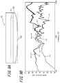
- FIG. 9(b) illustrates measured values in the case of providing a convexity 105 instead of the concavity 104 in the panel 102 ( FIG. 9(a) ).
- air represents the frequency characteristics of sound by path II and path III in FIG. 6
- vib represents the frequency characteristics of sound by path IV in FIG. 6
- air+vib represents the frequency characteristics of sound yielded by combining the sound of path II through path IV.
- FIG. 10 illustrates the frequency characteristics of "air+vib" for each of the cases of providing the concavity 104 and the convexity 105 in the panel 102.
- the structure in which the concavity 104 is provided in the panel 102 has a higher sound pressure in numerous frequency ranges, yielding excellent acoustic characteristics.
- the acoustic device is a hearing aid 1
- this example is not limiting.
- the acoustic device may be a headphone or earphone, in which case the microphone 20 is not provided.
- the acoustic device may reproduce sound based on music data stored in an internal memory of the acoustic device or sound based on music data stored on an external server or the like and transmitted over a network.
- the user is caused to hear sound by contacting the vibration unit 10 to the user's tragus from outside the user's ear and transmitting vibration to the tragus
- this example is not limiting.
- the user may be caused to hear sound by contacting the vibration unit 10 to a convex portion, such as the user's antitragus or the crus of antihelix, from outside the user's ear and transmitting vibration thereto.
- Contacting to the user's tragus or antitragus from outside the user's ear refers to contacting the vibration unit 10 to the tragus or antitragus approximately in parallel with the cheek or temple, without burying the vibration unit 10 in the external ear canal.
Landscapes
- Physics & Mathematics (AREA)
- Engineering & Computer Science (AREA)
- Acoustics & Sound (AREA)
- Signal Processing (AREA)
- Health & Medical Sciences (AREA)
- General Health & Medical Sciences (AREA)
- Neurosurgery (AREA)
- Otolaryngology (AREA)
- Details Of Audible-Bandwidth Transducers (AREA)
- Piezo-Electric Transducers For Audible Bands (AREA)
- Diaphragms For Electromechanical Transducers (AREA)
Abstract
Description
- This application claims priority to and the benefit of
Japanese Patent Application No. 2013-94436 filed April 26, 2013 - This disclosure relates to an acoustic device, such as a hearing aid.
- In one type of acoustic device, such as an open fitting hearing aid, a vent connecting the inside of the external ear canal to the outside is provided to alleviate an occlusion effect when wearing the hearing aid (for example, see
JP 2006-304147 A - PTL 1:
JP 2006-304147 A - In this open fitting hearing aid, however, low-frequency sound among the sound produced by the earphone escapes to the outside through the vent. Therefore, the sound pressure of low-frequency sound decreases, impairing a sense of volume. Reducing the diameter of the vent in order to prevent low-frequency sound from escaping, however, brings about an occlusion effect, thereby impairing a sense of comfort when wearing the hearing aid.
- It would therefore be helpful to provide an acoustic device that can suppress a loss in sense of volume and sense of comfort, two features which are difficult to combine.
- In order to solve the above problem, an acoustic device according to this disclosure for causing a user to hear sound includes:
- a vibration unit including a piezoelectric element that flexes and a panel that vibrates by being bent directly by the piezoelectric element, such that
- the panel includes a concavity, and the concavity is contacted to a user's ear.
- In the acoustic device, the concavity in the panel may contact the user's tragus from outside the user's ear and transmit vibration of the panel to the tragus.
- In the acoustic device, the concavity in the panel may contact the user's antitragus from outside the user's ear and transmit vibration of the panel to the antitragus.
- In the acoustic device, a principal surface of the panel may include a portion that contacts the ear and a portion that does not contact the ear.
- The acoustic device may be configured not to completely seal the user's external ear canal.
- In the acoustic device, the panel may vibrate with an antinode at a central region of the panel and a node on both sides of the antinode, and
a location at the central region of the panel may contact the tragus. - In the acoustic device, the panel may vibrate with an antinode at a central region of the panel and a node on both sides of the antinode, and
a location at the central region of the panel may contact the antitragus. - The sound-collecting acoustic device may further include a microphone.
- In the sound-collecting acoustic device, the vibration unit may generate an external ear canal radiated sound inside the user's ear.
- In the sound-collecting acoustic device, the vibration unit may be pressed against the user's ear with a force of 0.1 N to 3 N.
- In the sound-collecting acoustic device, the piezoelectric element may be plate-shaped, and
the panel may have an area between 0.8 and 10 times an area of a principal surface of the piezoelectric element. - This acoustic device can suppress a loss in sense of volume and sense of comfort.
- In the accompanying drawings:
-
FIG. 1 is a block diagram illustrating a hearing aid according to one of the disclosed embodiments; -
FIG. 2 schematically illustrates flexure of a panel and a piezoelectric element in a hearing aid according to one of the disclosed embodiments; -
FIG. 3 schematically illustrates the structure of a hearing aid according to one of the disclosed embodiments; -
FIG. 4 illustrates the portion of a hearing aid according to one of the disclosed embodiments that is in contact with the tragus; -
FIG. 5 is a side view in the thickness direction of a vibration unit; -
FIG. 6 schematically illustrates transmission of sound from a hearing aid according to one of the disclosed embodiments; -
FIGS. 7(a) through 7(d) schematically illustrate acoustic characteristics of various paths; -
FIG. 8 illustrates measured values of the acoustic characteristics of a hearing aid according to one of the disclosed embodiments; -
FIGS. 9(a) and 9(b) illustrate measured values in the case of providing a convexity instead of a concavity; and -
FIG. 10 illustrates a comparison of measured values in the cases of providing a concavity and a convexity. - The following describes embodiments of the disclosed device.
-
FIG. 1 is a block diagram of an acoustic device 1 according to one of the disclosed embodiments. The acoustic device 1 is, for example, a hearing aid 1 and includes avibration unit 10, amicrophone 20, acontroller 30, anadjustment interface 40, and amemory 50. - The
vibration unit 10 includes apiezoelectric element 101 that flexes and apanel 102 that vibrates by being bent directly by thepiezoelectric element 101.FIG. 2 schematically illustrates flexing of thepanel 102 due to thepiezoelectric element 101. Thevibration unit 10 causes the user to hear air-conducted sound and human body vibration sound due to vibration. Air-conducted sound is sound transmitted to the user's auditory nerve by air vibrations, caused by a vibrating object, that are transmitted through the external ear canal to the eardrum and cause the eardrum to vibrate. Human body vibration sound is sound that is transmitted to the user's auditory nerve through a portion of the user's body (such as the cartilage of the outer ear) that is contacting a vibrating object. - The
piezoelectric element 101 is formed by elements that, upon application of an electric signal (voltage), either expand and contract or bend (flex) in accordance with the electromechanical coupling coefficient of their constituent material. Ceramic or crystal elements, for example, may be used. Thepiezoelectric element 101 may be a unimorph, bimorph, or laminated piezoelectric element. Examples of a laminated piezoelectric element include a laminated unimorph element with layers of unimorph (for example, 16 or 24 layers) and a laminated bimorph element with layers of bimorph (for example, 16 or 24 layers). Such a laminated piezoelectric element may be configured with a laminated structure formed by a plurality of dielectric layers composed of, for example, lead zirconate titanate (PZT) and electrode layers disposed between the dielectric layers. Unimorph expands and contracts upon the application of an electric signal (voltage), and bimorph bends upon the application of an electric signal (voltage). - The
panel 102 is, for example, made from glass or a synthetic resin such as acrylic or the like. An exemplary shape of thepanel 102 is a plate, and the shape of thepanel 102 is described below as being a plate. - The
microphone 20 collects sound from a sound source, namely sound reaching the user's ear. - The
controller 30 executes various control pertaining to the hearing aid 1. Thecontroller 30 applies a predetermined electric signal (a voltage corresponding to a sound signal) to thepiezoelectric element 101. In greater detail, in thecontroller 30, an A/D converter 31 converts a sound signal collected by themicrophone 20 into a digital signal. Based on information on volume, sound quality, and the like from theadjustment interface 40 for volume and sound quality and on information stored in thememory 50, asignal processor 32 outputs a digital signal that drives thevibration unit 10. A D/A converter 33 converts the digital signal to an analog electric signal, which is then amplified by apiezoelectric amplifier 34. The resulting electric signal is applied to thepiezoelectric element 101. The voltage that thecontroller 30 applies to thepiezoelectric element 101 may, for example, be ±15 V. This is higher than ±5 V, i.e. the applied voltage of a so-called panel speaker for conduction of sound by air-conducted sound rather than human body vibration sound. In this way, sufficient vibration is generated in thepanel 102, so that a human body vibration sound can be generated via a part of the user's body. Note that the magnitude of the applied voltage used may be appropriately adjusted in accordance with the fixation strength of thepanel 102 or the performance of thepiezoelectric element 101. Upon thecontroller 30 applying the electric signal to thepiezoelectric element 101, thepiezoelectric element 101 expands and contracts or bends in the longitudinal direction. - At this point, the
panel 102 to which thepiezoelectric element 101 is attached vibrates by deforming in conjunction with the expansion and contraction or bending of thepiezoelectric element 101. Thepanel 102 flexes due to expansion and contraction or to bending of thepiezoelectric element 101. Thepanel 102 is bent directly by thepiezoelectric element 101. Stating that "thepanel 102 is bent directly by thepiezoelectric element 101" differs from the phenomenon utilized in known panel speakers, whereby thepanel 102 deforms upon vibration of a particular region of thepanel 102 due to the inertial force of a piezoelectric actuator constituted by disposing thepiezoelectric element 101 in the casing. Stating that "thepanel 102 is bent directly by thepiezoelectric element 101" refers instead to how expansion and contraction or bending (flexure) of thepiezoelectric element 101 directly bends thepanel 102 via the joining member. - Since the
panel 102 vibrates as described above, thepanel 102 generates air-conducted sound, and when the user contacts thepanel 102 to the tragus, thepanel 102 generates human body vibration sound via the tragus. Thepanel 102 preferably vibrates with locations near the edges of thepanel 102 as nodes and the central region as an antinode, and a location at the central region of thepanel 102 preferably contacts the tragus or antitragus. As a result, vibration of thepanel 102 can be efficiently transmitted to the tragus or the antitragus. -
FIG. 3 schematically illustrates the structure of the hearing aid 1 according to one of the disclosed embodiments. As illustrated inFIG. 3 , thevibration unit 10 is contacted to the user's tragus from outside the user's ear. Therefore, aholder 60 is provided. From a different angle,FIG. 4 illustrates thevibration unit 10 in contact with the tragus. As illustrated inFIG. 4 , thevibration unit 10 contacts the protruding tragus, and therefore by providing the below-describedconcavity 104 at the position of contact with the tragus, the area of contact between thevibration unit 10 and the tragus can be sufficiently insured without crushing the tragus. In this embodiment, an example is described in which the position of contact with the user's ear is the tragus. - As illustrated in
FIG. 3 , theholder 60 includes asupport 61, anear hook 62, and abody 63. Theholder 60 holds thevibration unit 10 at the position at which thevibration unit 10 contacts the user's ear (at the tragus). One end of thesupport 61 is connected to thevibration unit 10. Thesupport 61 has a hollow structure, and a lead wire is fed to thevibration unit 10 through this hollow structure. Thesupport 61 is rigid enough so that the angle of thevibration unit 10 does not change. The other end of thesupport 61 is connected to one end of theear hook 62. - The
ear hook 62 contacts the outside of the user's auricle to mount the hearing aid 1 in the user's ear. Theear hook 62 is preferably shaped as a hook conforming to the user's auricle so as to mount the hearing aid 1 stably in the user's ear. The other end of theear hook 62 is connected to thebody 63. Thebody 63 stores themicrophone 20,controller 30,adjustment interface 40, andmemory 50 therein. -
FIG. 5 is a side view of thevibration unit 10 as viewed in the thickness direction. As described above, thevibration unit 10 includes thepiezoelectric element 101 and thepanel 102. Thepiezoelectric element 101 is preferably shaped as a plate, as inFIG. 5 . - The
piezoelectric element 101 is joined to thepanel 102 by a joining member. The joining member is disposed between the principal surface of thepiezoelectric element 101 and the principal surface of thepanel 102. The joining member is preferably a non-heat hardening adhesive material or double-sided tape. Apart from the surface joined to thepanel 102, thepiezoelectric element 101 is covered by amold 103. - The principle surface of the
panel 102 includes theconcavity 104. Theconcavity 104 is a recessed portion in the central region of thepanel 102. Since the tragus projects outward, it is necessary to secure the area of contact by crushing the tragus when contacting a flat surface thereto. Conversely, since the hearing aid 1 includes theconcavity 104, and thisconcavity 104 contacts the tragus, the area of contact can be secured without crushing the tragus. Since it is not necessary to crush the tragus, theholder 60 can have a simple structure. Furthermore, since the tragus is not crushed, a sense of comfort can be maintained when the user wears the hearing aid 1. - The
panel 102 of thevibration unit 10 is pressed against the user's ear with a force of 0.1 N to 3 N. If thepanel 102 is pressed with a force between 0.1 N and 3 N, vibration by thepanel 102 is sufficiently transmitted to the ear. Furthermore, if the pressure is a small force of less than 3 N, the user suffers little fatigue even when wearing the hearing aid 1 for an extended period of time, thus maintaining a sense of comfort when wearing the hearing aid 1. - The
concavity 104 of thepanel 102 preferably includes a portion that contacts the user's ear (for example, the tragus) and a portion that does not contact the user's ear. By providing a portion that does not contact the user's ear within thepanel 102, it may be possible to generate air-conducted sound from this portion. - The principal surface of the
panel 102 preferably has an area between 0.8 and 10 times the area of the principal surface of thepiezoelectric element 101. If the principal surface of thepanel 102 has an area between 0.8 and 10 times the area of the principal surface of thepiezoelectric element 101, thepanel 102 can deform in conjunction with expansion and contraction or bending of thepiezoelectric element 101, and the area of contact with the user's ear can be sufficiently guaranteed. The area of the panel is, for example, more preferably between 0.8 and 5 times the area of the piezoelectric element. - Next, the acoustic characteristics of the hearing aid 1 according to one of the disclosed embodiments are described with reference to
FIGS. 6 through 8 . -
FIG. 6 schematically illustrates transmission of sound from the hearing aid 1 according to one of the disclosed embodiments. InFIG. 6 , the only illustrated portions of the hearing aid 1 are thevibration unit 10 and themicrophone 20. Themicrophone 20 collects sound from a sound source. By vibrating, thevibration unit 10 causes the user to hear the sound collected by themicrophone 20. - As illustrated in
FIG. 6 , sound from the sound source passes through the external ear canal from a portion not covered by thevibration unit 10 and reaches the eardrum directly (path I). Air-conducted sound due to vibration of thevibration unit 10 also passes through the external ear canal and reaches the eardrum (path II). Due to the vibration of thevibration unit 10, the external ear canal vibrates, and sound due to this vibration of the external ear canal (external ear canal radiated sound) reaches the eardrum (path III). Furthermore, human body vibration sound due to the vibration of thevibration unit 10 reaches the auditory nerve directly without passing through the eardrum (path IV). A portion of the air-conducted sound produced by thevibration unit 10 escapes to the outside (path V). -
FIGS. 7(a) through 7(d) schematically illustrate the acoustic characteristics of the various paths.FIG. 7(a) illustrates the acoustic characteristics of sound by path I, andFIG. 7(b) illustrates the acoustic characteristics of sound by path II and path III. For the sound by path II and path III, the sound pressure in the low-frequency sound region is low, since low-frequency sound escapes by path V.FIG. 7(c) illustrates the acoustic characteristics of path IV. As illustrated inFIG. 7(c) , in the human body vibration sound, the sound pressure of low-frequency sound is high, and low-frequency sound can be transmitted well.FIG. 7(d) illustrates the acoustic characteristics for a combination of sounds by paths I through IV, i.e. the actual acoustic characteristics heard by a user wearing the hearing aid 1. As illustrated inFIG. 7(d) , even though sound pressure of low-frequency sound escapes to the outside by path V, the sound pressure of low-frequency sound, namely sound pressure of low-frequency sound at 1 kHz or less in this embodiment, can be guaranteed by the human body vibration sound, thereby maintaining a sense of volume. -
FIG. 8 illustrates measured values of the frequency characteristics of the hearing aid 1. InFIG. 8 , "air" represents the frequency characteristics of sound by path II and path III inFIG. 6 , and "vib" represents the frequency characteristics of sound by path IV inFIG. 6 . Furthermore, "air+vib" represents the frequency characteristics of sound yielded by combining the sound of path II through path IV. As indicated by these measurement values, the sound pressure of low-frequency sound, namely sound pressure of low-frequency sound at 1 kHz or less in this embodiment, can be guaranteed by the human body vibration sound, thereby suppressing a loss in the sense of volume. -
FIG. 9(b) illustrates measured values in the case of providing aconvexity 105 instead of theconcavity 104 in the panel 102 (FIG. 9(a) ). InFIG. 9(b) , "air" represents the frequency characteristics of sound by path II and path III inFIG. 6 , and "vib" represents the frequency characteristics of sound by path IV inFIG. 6 . Furthermore, "air+vib" represents the frequency characteristics of sound yielded by combining the sound of path II through path IV.FIG. 10 illustrates the frequency characteristics of "air+vib" for each of the cases of providing theconcavity 104 and theconvexity 105 in thepanel 102. As illustrated inFIG. 10 , the structure in which theconcavity 104 is provided in thepanel 102 has a higher sound pressure in numerous frequency ranges, yielding excellent acoustic characteristics. - While an example in which the acoustic device is a hearing aid 1 has been described in this embodiment, this example is not limiting. For example, the acoustic device may be a headphone or earphone, in which case the
microphone 20 is not provided. In this case, the acoustic device may reproduce sound based on music data stored in an internal memory of the acoustic device or sound based on music data stored on an external server or the like and transmitted over a network. - In this embodiment, while an example has been illustrated in which the user is caused to hear sound by contacting the
vibration unit 10 to the user's tragus from outside the user's ear and transmitting vibration to the tragus, this example is not limiting. For example, the user may be caused to hear sound by contacting thevibration unit 10 to a convex portion, such as the user's antitragus or the crus of antihelix, from outside the user's ear and transmitting vibration thereto. "Contacting to the user's tragus or antitragus from outside the user's ear" refers to contacting thevibration unit 10 to the tragus or antitragus approximately in parallel with the cheek or temple, without burying thevibration unit 10 in the external ear canal. - Although this disclosure is based on embodiments and drawings, it is to be noted that various changes and modifications will be apparent to those skilled in the art based on this disclosure. Therefore, such changes and modifications are to be understood as included within the scope of this disclosure. For example, the functions and the like included in the various units and members may be reordered in any logically consistent way. Furthermore, units and members may be combined into one or divided.
-
- 1
- Acoustic device (hearing aid)
- 10
- Vibration unit
- 20
- Microphone
- 30
- Controller
- 31
- A/D converter
- 32
- Signal processor
- 33
- D/A converter
- 34
- Piezoelectric amplifier
- 40
- Adjustment interface
- 50
- Memory
- 60
- Holder
- 61
- Support
- 62
- Ear hook
- 63
- Body
- 101
- Piezoelectric element
- 102
- Panel
- 103
- Mold
- 104
- Concavity
- 105
- Convexity
Claims (11)
- An acoustic device for causing a user to hear sound, comprising:a vibration unit including a piezoelectric element that flexes and a panel that vibrates by being bent directly by the piezoelectric element, whereinthe panel includes a concavity, and the concavity is contacted to a user's ear.
- The acoustic device of claim 1, wherein the concavity in the panel contacts the user's tragus from outside the user's ear and transmits vibration of the panel to the tragus.
- The acoustic device of claim 1, wherein the concavity in the panel contacts the user's antitragus from outside the user's ear and transmits vibration of the panel to the antitragus.
- The acoustic device of claim 1, wherein a principal surface of the panel includes a portion that contacts the ear and a portion that does not contact the ear.
- The acoustic device of claim 1, wherein the acoustic device does not completely seal the user's external ear canal.
- The acoustic device of claim 2, wherein
the panel vibrates with an antinode at a central region of the panel and a node on both sides of the antinode, and
a location at the central region of the panel contacts the tragus. - The acoustic device of claim 3, wherein
the panel vibrates with an antinode at a central region of the panel and a node on both sides of the antinode, and
a location at the central region of the panel contacts the antitragus. - The acoustic device of claim 1, further comprising a microphone.
- The sound-collecting acoustic device of claim 1, wherein the vibration unit generates an external ear canal radiated sound inside the user's ear.
- The acoustic device of claim 1, wherein the vibration unit is pressed against the user's ear with a force of 0.1 N to 3 N.
- The sound-collecting acoustic device of claim 1, wherein
the piezoelectric element is plate-shaped, and
the panel has an area between 0.8 and 10 times an area of a principal surface of the piezoelectric element.
Applications Claiming Priority (2)
| Application Number | Priority Date | Filing Date | Title |
|---|---|---|---|
| JP2013094436A JP6279225B2 (en) | 2013-04-26 | 2013-04-26 | Audio equipment |
| PCT/JP2014/062035 WO2014175464A1 (en) | 2013-04-26 | 2014-04-23 | Acoustic apparatus |
Publications (3)
| Publication Number | Publication Date |
|---|---|
| EP2991377A1 true EP2991377A1 (en) | 2016-03-02 |
| EP2991377A4 EP2991377A4 (en) | 2016-12-21 |
| EP2991377B1 EP2991377B1 (en) | 2019-12-04 |
Family
ID=51792023
Family Applications (1)
| Application Number | Title | Priority Date | Filing Date |
|---|---|---|---|
| EP14788772.3A Active EP2991377B1 (en) | 2013-04-26 | 2014-04-23 | Acoustic apparatus |
Country Status (4)
| Country | Link |
|---|---|
| US (1) | US9485593B2 (en) |
| EP (1) | EP2991377B1 (en) |
| JP (1) | JP6279225B2 (en) |
| WO (1) | WO2014175464A1 (en) |
Families Citing this family (4)
| Publication number | Priority date | Publication date | Assignee | Title |
|---|---|---|---|---|
| US10531173B2 (en) * | 2018-05-24 | 2020-01-07 | Facebook Technologies, Llc | Apparatus, system, and method for tragus conduction hearable device |
| US10602258B2 (en) * | 2018-05-30 | 2020-03-24 | Facebook Technologies, Llc | Manufacturing a cartilage conduction audio device |
| CN111698595A (en) * | 2019-03-15 | 2020-09-22 | 华一声学股份有限公司 | Multi-audio earphone |
| CN115053539A (en) * | 2020-08-29 | 2022-09-13 | 深圳市韶音科技有限公司 | Hearing assisting device |
Family Cites Families (17)
| Publication number | Priority date | Publication date | Assignee | Title |
|---|---|---|---|---|
| US2470933A (en) * | 1944-06-05 | 1949-05-24 | Zenith Radio Corp | Flexible-surfaced bone conduction hearing aid unit |
| JPS5588497A (en) * | 1978-12-25 | 1980-07-04 | Matsushita Electric Ind Co Ltd | Ear receiver |
| JP3774158B2 (en) * | 2002-03-07 | 2006-05-10 | 日本電信電話株式会社 | Earphone device |
| GB0321617D0 (en) * | 2003-09-10 | 2003-10-15 | New Transducers Ltd | Audio apparatus |
| JP2005348193A (en) * | 2004-06-04 | 2005-12-15 | Nec Tokin Corp | Receiver |
| JP4166764B2 (en) | 2005-04-25 | 2008-10-15 | リオン株式会社 | Determination of vent dimensions for ear-shaped hearing aids |
| JP4683635B2 (en) * | 2005-09-30 | 2011-05-18 | Necトーキン株式会社 | Receiver |
| JP2007165938A (en) | 2005-11-18 | 2007-06-28 | Nec Tokin Corp | Earphone device |
| WO2008029515A1 (en) * | 2006-09-07 | 2008-03-13 | Temco Japan Co., Ltd. | Bone conduction speaker |
| JP2009232443A (en) * | 2008-02-29 | 2009-10-08 | Nec Tokin Corp | Receiver |
| JP2009302815A (en) * | 2008-06-12 | 2009-12-24 | Shinko Mechatronics Corp | Bone conduction device attached to headphone |
| CA2807808A1 (en) * | 2010-08-09 | 2012-02-16 | #3248362 Nova Scotia Limited | Personal listening device |
| CN104717590B (en) | 2010-12-27 | 2020-09-15 | 株式会社精好 | Mobile telephone system |
| US8521239B2 (en) | 2010-12-27 | 2013-08-27 | Rohm Co., Ltd. | Mobile telephone |
| JP5848510B2 (en) * | 2011-03-23 | 2016-01-27 | 株式会社ファインウェル | Mobile phone and sound signal output device |
| JP5918660B2 (en) * | 2011-09-13 | 2016-05-18 | Kddi株式会社 | Audio transmission device |
| JP6359807B2 (en) * | 2013-06-12 | 2018-07-18 | 京セラ株式会社 | Sound reproduction equipment |
-
2013
- 2013-04-26 JP JP2013094436A patent/JP6279225B2/en active Active
-
2014
- 2014-04-23 US US14/786,376 patent/US9485593B2/en active Active
- 2014-04-23 EP EP14788772.3A patent/EP2991377B1/en active Active
- 2014-04-23 WO PCT/JP2014/062035 patent/WO2014175464A1/en not_active Ceased
Also Published As
| Publication number | Publication date |
|---|---|
| JP2014216941A (en) | 2014-11-17 |
| US20160088409A1 (en) | 2016-03-24 |
| EP2991377B1 (en) | 2019-12-04 |
| US9485593B2 (en) | 2016-11-01 |
| JP6279225B2 (en) | 2018-02-14 |
| WO2014175464A1 (en) | 2014-10-30 |
| EP2991377A4 (en) | 2016-12-21 |
Similar Documents
| Publication | Publication Date | Title |
|---|---|---|
| US9686622B2 (en) | Acoustic reproduction device and sound-collecting acoustic reproduction device | |
| JP6359807B2 (en) | Sound reproduction equipment | |
| CN204031381U (en) | Electronic equipment | |
| JP4683635B2 (en) | Receiver | |
| JP6219889B2 (en) | Audio equipment | |
| JP6092526B2 (en) | Electronics | |
| US9807520B2 (en) | Acoustic device and method of using the same | |
| WO2013145758A1 (en) | Electronic device | |
| JP2007104548A (en) | Ear receiving device | |
| US9591414B2 (en) | Acoustic device | |
| US9485593B2 (en) | Acoustic device | |
| JP6022211B2 (en) | Electronics | |
| US9578406B2 (en) | Acoustic device | |
| WO2014174835A1 (en) | Electronic device | |
| JP2018098596A (en) | Ear-hole type hearing aid | |
| JP6282825B2 (en) | Electronics | |
| JP5856199B2 (en) | Electronics | |
| JP5900986B2 (en) | Electronics |
Legal Events
| Date | Code | Title | Description |
|---|---|---|---|
| PUAI | Public reference made under article 153(3) epc to a published international application that has entered the european phase |
Free format text: ORIGINAL CODE: 0009012 |
|
| 17P | Request for examination filed |
Effective date: 20151023 |
|
| AK | Designated contracting states |
Kind code of ref document: A1 Designated state(s): AL AT BE BG CH CY CZ DE DK EE ES FI FR GB GR HR HU IE IS IT LI LT LU LV MC MK MT NL NO PL PT RO RS SE SI SK SM TR |
|
| AX | Request for extension of the european patent |
Extension state: BA ME |
|
| DAX | Request for extension of the european patent (deleted) | ||
| REG | Reference to a national code |
Ref country code: DE Ref legal event code: R079 Ref document number: 602014057881 Country of ref document: DE Free format text: PREVIOUS MAIN CLASS: H04R0025000000 Ipc: H04R0025020000 |
|
| A4 | Supplementary search report drawn up and despatched |
Effective date: 20161121 |
|
| RIC1 | Information provided on ipc code assigned before grant |
Ipc: H04R 17/00 20060101ALI20161114BHEP Ipc: H04R 25/02 20060101AFI20161114BHEP |
|
| STAA | Information on the status of an ep patent application or granted ep patent |
Free format text: STATUS: EXAMINATION IS IN PROGRESS |
|
| 17Q | First examination report despatched |
Effective date: 20180313 |
|
| GRAP | Despatch of communication of intention to grant a patent |
Free format text: ORIGINAL CODE: EPIDOSNIGR1 |
|
| STAA | Information on the status of an ep patent application or granted ep patent |
Free format text: STATUS: GRANT OF PATENT IS INTENDED |
|
| INTG | Intention to grant announced |
Effective date: 20190711 |
|
| GRAS | Grant fee paid |
Free format text: ORIGINAL CODE: EPIDOSNIGR3 |
|
| GRAA | (expected) grant |
Free format text: ORIGINAL CODE: 0009210 |
|
| STAA | Information on the status of an ep patent application or granted ep patent |
Free format text: STATUS: THE PATENT HAS BEEN GRANTED |
|
| AK | Designated contracting states |
Kind code of ref document: B1 Designated state(s): AL AT BE BG CH CY CZ DE DK EE ES FI FR GB GR HR HU IE IS IT LI LT LU LV MC MK MT NL NO PL PT RO RS SE SI SK SM TR |
|
| REG | Reference to a national code |
Ref country code: GB Ref legal event code: FG4D |
|
| REG | Reference to a national code |
Ref country code: CH Ref legal event code: EP |
|
| REG | Reference to a national code |
Ref country code: AT Ref legal event code: REF Ref document number: 1211029 Country of ref document: AT Kind code of ref document: T Effective date: 20191215 |
|
| REG | Reference to a national code |
Ref country code: DE Ref legal event code: R096 Ref document number: 602014057881 Country of ref document: DE |
|
| REG | Reference to a national code |
Ref country code: IE Ref legal event code: FG4D |
|
| REG | Reference to a national code |
Ref country code: NL Ref legal event code: MP Effective date: 20191204 |
|
| REG | Reference to a national code |
Ref country code: LT Ref legal event code: MG4D |
|
| PG25 | Lapsed in a contracting state [announced via postgrant information from national office to epo] |
Ref country code: BG Free format text: LAPSE BECAUSE OF FAILURE TO SUBMIT A TRANSLATION OF THE DESCRIPTION OR TO PAY THE FEE WITHIN THE PRESCRIBED TIME-LIMIT Effective date: 20200304 Ref country code: FI Free format text: LAPSE BECAUSE OF FAILURE TO SUBMIT A TRANSLATION OF THE DESCRIPTION OR TO PAY THE FEE WITHIN THE PRESCRIBED TIME-LIMIT Effective date: 20191204 Ref country code: GR Free format text: LAPSE BECAUSE OF FAILURE TO SUBMIT A TRANSLATION OF THE DESCRIPTION OR TO PAY THE FEE WITHIN THE PRESCRIBED TIME-LIMIT Effective date: 20200305 Ref country code: NO Free format text: LAPSE BECAUSE OF FAILURE TO SUBMIT A TRANSLATION OF THE DESCRIPTION OR TO PAY THE FEE WITHIN THE PRESCRIBED TIME-LIMIT Effective date: 20200304 Ref country code: LT Free format text: LAPSE BECAUSE OF FAILURE TO SUBMIT A TRANSLATION OF THE DESCRIPTION OR TO PAY THE FEE WITHIN THE PRESCRIBED TIME-LIMIT Effective date: 20191204 Ref country code: SE Free format text: LAPSE BECAUSE OF FAILURE TO SUBMIT A TRANSLATION OF THE DESCRIPTION OR TO PAY THE FEE WITHIN THE PRESCRIBED TIME-LIMIT Effective date: 20191204 Ref country code: LV Free format text: LAPSE BECAUSE OF FAILURE TO SUBMIT A TRANSLATION OF THE DESCRIPTION OR TO PAY THE FEE WITHIN THE PRESCRIBED TIME-LIMIT Effective date: 20191204 |
|
| PG25 | Lapsed in a contracting state [announced via postgrant information from national office to epo] |
Ref country code: RS Free format text: LAPSE BECAUSE OF FAILURE TO SUBMIT A TRANSLATION OF THE DESCRIPTION OR TO PAY THE FEE WITHIN THE PRESCRIBED TIME-LIMIT Effective date: 20191204 Ref country code: HR Free format text: LAPSE BECAUSE OF FAILURE TO SUBMIT A TRANSLATION OF THE DESCRIPTION OR TO PAY THE FEE WITHIN THE PRESCRIBED TIME-LIMIT Effective date: 20191204 |
|
| PG25 | Lapsed in a contracting state [announced via postgrant information from national office to epo] |
Ref country code: AL Free format text: LAPSE BECAUSE OF FAILURE TO SUBMIT A TRANSLATION OF THE DESCRIPTION OR TO PAY THE FEE WITHIN THE PRESCRIBED TIME-LIMIT Effective date: 20191204 |
|
| PG25 | Lapsed in a contracting state [announced via postgrant information from national office to epo] |
Ref country code: ES Free format text: LAPSE BECAUSE OF FAILURE TO SUBMIT A TRANSLATION OF THE DESCRIPTION OR TO PAY THE FEE WITHIN THE PRESCRIBED TIME-LIMIT Effective date: 20191204 Ref country code: PT Free format text: LAPSE BECAUSE OF FAILURE TO SUBMIT A TRANSLATION OF THE DESCRIPTION OR TO PAY THE FEE WITHIN THE PRESCRIBED TIME-LIMIT Effective date: 20200429 Ref country code: EE Free format text: LAPSE BECAUSE OF FAILURE TO SUBMIT A TRANSLATION OF THE DESCRIPTION OR TO PAY THE FEE WITHIN THE PRESCRIBED TIME-LIMIT Effective date: 20191204 Ref country code: RO Free format text: LAPSE BECAUSE OF FAILURE TO SUBMIT A TRANSLATION OF THE DESCRIPTION OR TO PAY THE FEE WITHIN THE PRESCRIBED TIME-LIMIT Effective date: 20191204 Ref country code: CZ Free format text: LAPSE BECAUSE OF FAILURE TO SUBMIT A TRANSLATION OF THE DESCRIPTION OR TO PAY THE FEE WITHIN THE PRESCRIBED TIME-LIMIT Effective date: 20191204 Ref country code: NL Free format text: LAPSE BECAUSE OF FAILURE TO SUBMIT A TRANSLATION OF THE DESCRIPTION OR TO PAY THE FEE WITHIN THE PRESCRIBED TIME-LIMIT Effective date: 20191204 |
|
| PG25 | Lapsed in a contracting state [announced via postgrant information from national office to epo] |
Ref country code: SK Free format text: LAPSE BECAUSE OF FAILURE TO SUBMIT A TRANSLATION OF THE DESCRIPTION OR TO PAY THE FEE WITHIN THE PRESCRIBED TIME-LIMIT Effective date: 20191204 Ref country code: IS Free format text: LAPSE BECAUSE OF FAILURE TO SUBMIT A TRANSLATION OF THE DESCRIPTION OR TO PAY THE FEE WITHIN THE PRESCRIBED TIME-LIMIT Effective date: 20200404 Ref country code: SM Free format text: LAPSE BECAUSE OF FAILURE TO SUBMIT A TRANSLATION OF THE DESCRIPTION OR TO PAY THE FEE WITHIN THE PRESCRIBED TIME-LIMIT Effective date: 20191204 |
|
| REG | Reference to a national code |
Ref country code: DE Ref legal event code: R097 Ref document number: 602014057881 Country of ref document: DE |
|
| REG | Reference to a national code |
Ref country code: AT Ref legal event code: MK05 Ref document number: 1211029 Country of ref document: AT Kind code of ref document: T Effective date: 20191204 |
|
| PLBE | No opposition filed within time limit |
Free format text: ORIGINAL CODE: 0009261 |
|
| STAA | Information on the status of an ep patent application or granted ep patent |
Free format text: STATUS: NO OPPOSITION FILED WITHIN TIME LIMIT |
|
| PG25 | Lapsed in a contracting state [announced via postgrant information from national office to epo] |
Ref country code: DK Free format text: LAPSE BECAUSE OF FAILURE TO SUBMIT A TRANSLATION OF THE DESCRIPTION OR TO PAY THE FEE WITHIN THE PRESCRIBED TIME-LIMIT Effective date: 20191204 |
|
| 26N | No opposition filed |
Effective date: 20200907 |
|
| PG25 | Lapsed in a contracting state [announced via postgrant information from national office to epo] |
Ref country code: PL Free format text: LAPSE BECAUSE OF FAILURE TO SUBMIT A TRANSLATION OF THE DESCRIPTION OR TO PAY THE FEE WITHIN THE PRESCRIBED TIME-LIMIT Effective date: 20191204 Ref country code: MC Free format text: LAPSE BECAUSE OF FAILURE TO SUBMIT A TRANSLATION OF THE DESCRIPTION OR TO PAY THE FEE WITHIN THE PRESCRIBED TIME-LIMIT Effective date: 20191204 Ref country code: SI Free format text: LAPSE BECAUSE OF FAILURE TO SUBMIT A TRANSLATION OF THE DESCRIPTION OR TO PAY THE FEE WITHIN THE PRESCRIBED TIME-LIMIT Effective date: 20191204 Ref country code: AT Free format text: LAPSE BECAUSE OF FAILURE TO SUBMIT A TRANSLATION OF THE DESCRIPTION OR TO PAY THE FEE WITHIN THE PRESCRIBED TIME-LIMIT Effective date: 20191204 |
|
| REG | Reference to a national code |
Ref country code: CH Ref legal event code: PL |
|
| PG25 | Lapsed in a contracting state [announced via postgrant information from national office to epo] |
Ref country code: LI Free format text: LAPSE BECAUSE OF NON-PAYMENT OF DUE FEES Effective date: 20200430 Ref country code: CH Free format text: LAPSE BECAUSE OF NON-PAYMENT OF DUE FEES Effective date: 20200430 Ref country code: LU Free format text: LAPSE BECAUSE OF NON-PAYMENT OF DUE FEES Effective date: 20200423 Ref country code: FR Free format text: LAPSE BECAUSE OF NON-PAYMENT OF DUE FEES Effective date: 20200430 Ref country code: IT Free format text: LAPSE BECAUSE OF FAILURE TO SUBMIT A TRANSLATION OF THE DESCRIPTION OR TO PAY THE FEE WITHIN THE PRESCRIBED TIME-LIMIT Effective date: 20191204 |
|
| REG | Reference to a national code |
Ref country code: BE Ref legal event code: MM Effective date: 20200430 |
|
| PG25 | Lapsed in a contracting state [announced via postgrant information from national office to epo] |
Ref country code: BE Free format text: LAPSE BECAUSE OF NON-PAYMENT OF DUE FEES Effective date: 20200430 |
|
| GBPC | Gb: european patent ceased through non-payment of renewal fee |
Effective date: 20200423 |
|
| PG25 | Lapsed in a contracting state [announced via postgrant information from national office to epo] |
Ref country code: IE Free format text: LAPSE BECAUSE OF NON-PAYMENT OF DUE FEES Effective date: 20200423 Ref country code: GB Free format text: LAPSE BECAUSE OF NON-PAYMENT OF DUE FEES Effective date: 20200423 |
|
| PG25 | Lapsed in a contracting state [announced via postgrant information from national office to epo] |
Ref country code: TR Free format text: LAPSE BECAUSE OF FAILURE TO SUBMIT A TRANSLATION OF THE DESCRIPTION OR TO PAY THE FEE WITHIN THE PRESCRIBED TIME-LIMIT Effective date: 20191204 Ref country code: MT Free format text: LAPSE BECAUSE OF FAILURE TO SUBMIT A TRANSLATION OF THE DESCRIPTION OR TO PAY THE FEE WITHIN THE PRESCRIBED TIME-LIMIT Effective date: 20191204 Ref country code: CY Free format text: LAPSE BECAUSE OF FAILURE TO SUBMIT A TRANSLATION OF THE DESCRIPTION OR TO PAY THE FEE WITHIN THE PRESCRIBED TIME-LIMIT Effective date: 20191204 |
|
| PG25 | Lapsed in a contracting state [announced via postgrant information from national office to epo] |
Ref country code: MK Free format text: LAPSE BECAUSE OF FAILURE TO SUBMIT A TRANSLATION OF THE DESCRIPTION OR TO PAY THE FEE WITHIN THE PRESCRIBED TIME-LIMIT Effective date: 20191204 |
|
| P01 | Opt-out of the competence of the unified patent court (upc) registered |
Effective date: 20230508 |
|
| PGFP | Annual fee paid to national office [announced via postgrant information from national office to epo] |
Ref country code: DE Payment date: 20240227 Year of fee payment: 11 |
|
| REG | Reference to a national code |
Ref country code: DE Ref legal event code: R119 Ref document number: 602014057881 Country of ref document: DE |
|
| PG25 | Lapsed in a contracting state [announced via postgrant information from national office to epo] |
Ref country code: DE Free format text: LAPSE BECAUSE OF NON-PAYMENT OF DUE FEES Effective date: 20251104 |