EP2991061A1 - Fastner with embedded identifier circuit - Google Patents
Fastner with embedded identifier circuit Download PDFInfo
- Publication number
- EP2991061A1 EP2991061A1 EP14182902.8A EP14182902A EP2991061A1 EP 2991061 A1 EP2991061 A1 EP 2991061A1 EP 14182902 A EP14182902 A EP 14182902A EP 2991061 A1 EP2991061 A1 EP 2991061A1
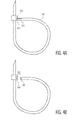
- Authority
- EP
- European Patent Office
- Prior art keywords
- fastener
- strip
- package
- antenna
- zip tie
- Prior art date
- Legal status (The legal status is an assumption and is not a legal conclusion. Google has not performed a legal analysis and makes no representation as to the accuracy of the status listed.)
- Granted
Links
Images




Classifications
-
- B—PERFORMING OPERATIONS; TRANSPORTING
- B65—CONVEYING; PACKING; STORING; HANDLING THIN OR FILAMENTARY MATERIAL
- B65D—CONTAINERS FOR STORAGE OR TRANSPORT OF ARTICLES OR MATERIALS, e.g. BAGS, BARRELS, BOTTLES, BOXES, CANS, CARTONS, CRATES, DRUMS, JARS, TANKS, HOPPERS, FORWARDING CONTAINERS; ACCESSORIES, CLOSURES, OR FITTINGS THEREFOR; PACKAGING ELEMENTS; PACKAGES
- B65D63/00—Flexible elongated elements, e.g. straps, for bundling or supporting articles
- B65D63/10—Non-metallic straps, tapes, or bands; Filamentary elements, e.g. strings, threads or wires; Joints between ends thereof
- B65D63/1018—Joints produced by application of integral securing members, e.g. buckles, wedges, tongue and slot, locking head and teeth or the like
- B65D63/1027—Joints produced by application of integral securing members, e.g. buckles, wedges, tongue and slot, locking head and teeth or the like the integral securing member being formed as a female and male locking member, e.g. locking head and locking teeth, or the like
-
- G—PHYSICS
- G06—COMPUTING OR CALCULATING; COUNTING
- G06K—GRAPHICAL DATA READING; PRESENTATION OF DATA; RECORD CARRIERS; HANDLING RECORD CARRIERS
- G06K19/00—Record carriers for use with machines and with at least a part designed to carry digital markings
- G06K19/06—Record carriers for use with machines and with at least a part designed to carry digital markings characterised by the kind of the digital marking, e.g. shape, nature, code
- G06K19/067—Record carriers with conductive marks, printed circuits or semiconductor circuit elements, e.g. credit or identity cards also with resonating or responding marks without active components
- G06K19/07—Record carriers with conductive marks, printed circuits or semiconductor circuit elements, e.g. credit or identity cards also with resonating or responding marks without active components with integrated circuit chips
- G06K19/077—Constructional details, e.g. mounting of circuits in the carrier
- G06K19/07749—Constructional details, e.g. mounting of circuits in the carrier the record carrier being capable of non-contact communication, e.g. constructional details of the antenna of a non-contact smart card
- G06K19/07758—Constructional details, e.g. mounting of circuits in the carrier the record carrier being capable of non-contact communication, e.g. constructional details of the antenna of a non-contact smart card arrangements for adhering the record carrier to further objects or living beings, functioning as an identification tag
- G06K19/07762—Constructional details, e.g. mounting of circuits in the carrier the record carrier being capable of non-contact communication, e.g. constructional details of the antenna of a non-contact smart card arrangements for adhering the record carrier to further objects or living beings, functioning as an identification tag the adhering arrangement making the record carrier wearable, e.g. having the form of a ring, watch, glove or bracelet
-
- G—PHYSICS
- G06—COMPUTING OR CALCULATING; COUNTING
- G06K—GRAPHICAL DATA READING; PRESENTATION OF DATA; RECORD CARRIERS; HANDLING RECORD CARRIERS
- G06K19/00—Record carriers for use with machines and with at least a part designed to carry digital markings
- G06K19/06—Record carriers for use with machines and with at least a part designed to carry digital markings characterised by the kind of the digital marking, e.g. shape, nature, code
- G06K19/067—Record carriers with conductive marks, printed circuits or semiconductor circuit elements, e.g. credit or identity cards also with resonating or responding marks without active components
- G06K19/07—Record carriers with conductive marks, printed circuits or semiconductor circuit elements, e.g. credit or identity cards also with resonating or responding marks without active components with integrated circuit chips
- G06K19/077—Constructional details, e.g. mounting of circuits in the carrier
- G06K19/07749—Constructional details, e.g. mounting of circuits in the carrier the record carrier being capable of non-contact communication, e.g. constructional details of the antenna of a non-contact smart card
- G06K19/0775—Constructional details, e.g. mounting of circuits in the carrier the record carrier being capable of non-contact communication, e.g. constructional details of the antenna of a non-contact smart card arrangements for connecting the integrated circuit to the antenna
-
- G—PHYSICS
- G06—COMPUTING OR CALCULATING; COUNTING
- G06K—GRAPHICAL DATA READING; PRESENTATION OF DATA; RECORD CARRIERS; HANDLING RECORD CARRIERS
- G06K19/00—Record carriers for use with machines and with at least a part designed to carry digital markings
- G06K19/06—Record carriers for use with machines and with at least a part designed to carry digital markings characterised by the kind of the digital marking, e.g. shape, nature, code
- G06K19/067—Record carriers with conductive marks, printed circuits or semiconductor circuit elements, e.g. credit or identity cards also with resonating or responding marks without active components
- G06K19/07—Record carriers with conductive marks, printed circuits or semiconductor circuit elements, e.g. credit or identity cards also with resonating or responding marks without active components with integrated circuit chips
- G06K19/077—Constructional details, e.g. mounting of circuits in the carrier
- G06K19/07749—Constructional details, e.g. mounting of circuits in the carrier the record carrier being capable of non-contact communication, e.g. constructional details of the antenna of a non-contact smart card
- G06K19/07758—Constructional details, e.g. mounting of circuits in the carrier the record carrier being capable of non-contact communication, e.g. constructional details of the antenna of a non-contact smart card arrangements for adhering the record carrier to further objects or living beings, functioning as an identification tag
-
- G—PHYSICS
- G06—COMPUTING OR CALCULATING; COUNTING
- G06K—GRAPHICAL DATA READING; PRESENTATION OF DATA; RECORD CARRIERS; HANDLING RECORD CARRIERS
- G06K19/00—Record carriers for use with machines and with at least a part designed to carry digital markings
- G06K19/06—Record carriers for use with machines and with at least a part designed to carry digital markings characterised by the kind of the digital marking, e.g. shape, nature, code
- G06K19/067—Record carriers with conductive marks, printed circuits or semiconductor circuit elements, e.g. credit or identity cards also with resonating or responding marks without active components
- G06K19/07—Record carriers with conductive marks, printed circuits or semiconductor circuit elements, e.g. credit or identity cards also with resonating or responding marks without active components with integrated circuit chips
- G06K19/077—Constructional details, e.g. mounting of circuits in the carrier
- G06K19/07749—Constructional details, e.g. mounting of circuits in the carrier the record carrier being capable of non-contact communication, e.g. constructional details of the antenna of a non-contact smart card
- G06K19/07773—Antenna details
- G06K19/07777—Antenna details the antenna being of the inductive type
- G06K19/07779—Antenna details the antenna being of the inductive type the inductive antenna being a coil
- G06K19/07783—Antenna details the antenna being of the inductive type the inductive antenna being a coil the coil being planar
-
- G—PHYSICS
- G06—COMPUTING OR CALCULATING; COUNTING
- G06K—GRAPHICAL DATA READING; PRESENTATION OF DATA; RECORD CARRIERS; HANDLING RECORD CARRIERS
- G06K19/00—Record carriers for use with machines and with at least a part designed to carry digital markings
- G06K19/06—Record carriers for use with machines and with at least a part designed to carry digital markings characterised by the kind of the digital marking, e.g. shape, nature, code
- G06K19/067—Record carriers with conductive marks, printed circuits or semiconductor circuit elements, e.g. credit or identity cards also with resonating or responding marks without active components
- G06K19/07—Record carriers with conductive marks, printed circuits or semiconductor circuit elements, e.g. credit or identity cards also with resonating or responding marks without active components with integrated circuit chips
- G06K19/077—Constructional details, e.g. mounting of circuits in the carrier
- G06K19/07749—Constructional details, e.g. mounting of circuits in the carrier the record carrier being capable of non-contact communication, e.g. constructional details of the antenna of a non-contact smart card
- G06K19/07798—Constructional details, e.g. mounting of circuits in the carrier the record carrier being capable of non-contact communication, e.g. constructional details of the antenna of a non-contact smart card part of the antenna or the integrated circuit being adapted for rupturing or breaking, e.g. record carriers functioning as sealing devices for detecting not-authenticated opening of containers
-
- G—PHYSICS
- G09—EDUCATION; CRYPTOGRAPHY; DISPLAY; ADVERTISING; SEALS
- G09F—DISPLAYING; ADVERTISING; SIGNS; LABELS OR NAME-PLATES; SEALS
- G09F3/00—Labels, tag tickets, or similar identification or indication means; Seals; Postage or like stamps
- G09F3/02—Forms or constructions
- G09F3/03—Forms or constructions of security seals
- G09F3/0305—Forms or constructions of security seals characterised by the type of seal used
- G09F3/0329—Forms or constructions of security seals characterised by the type of seal used having electronic sealing means
- G09F3/0335—Forms or constructions of security seals characterised by the type of seal used having electronic sealing means using RFID tags
-
- G—PHYSICS
- G09—EDUCATION; CRYPTOGRAPHY; DISPLAY; ADVERTISING; SEALS
- G09F—DISPLAYING; ADVERTISING; SIGNS; LABELS OR NAME-PLATES; SEALS
- G09F3/00—Labels, tag tickets, or similar identification or indication means; Seals; Postage or like stamps
- G09F3/02—Forms or constructions
- G09F3/03—Forms or constructions of security seals
- G09F3/0305—Forms or constructions of security seals characterised by the type of seal used
- G09F3/037—Forms or constructions of security seals characterised by the type of seal used having tie-wrap sealing means
-
- H—ELECTRICITY
- H01—ELECTRIC ELEMENTS
- H01Q—ANTENNAS, i.e. RADIO AERIALS
- H01Q1/00—Details of, or arrangements associated with, antennas
- H01Q1/12—Supports; Mounting means
- H01Q1/22—Supports; Mounting means by structural association with other equipment or articles
- H01Q1/2208—Supports; Mounting means by structural association with other equipment or articles associated with components used in interrogation type services, i.e. in systems for information exchange between an interrogator/reader and a tag/transponder, e.g. in Radio Frequency Identification [RFID] systems
- H01Q1/2225—Supports; Mounting means by structural association with other equipment or articles associated with components used in interrogation type services, i.e. in systems for information exchange between an interrogator/reader and a tag/transponder, e.g. in Radio Frequency Identification [RFID] systems used in active tags, i.e. provided with its own power source or in passive tags, i.e. deriving power from RF signal
-
- B—PERFORMING OPERATIONS; TRANSPORTING
- B65—CONVEYING; PACKING; STORING; HANDLING THIN OR FILAMENTARY MATERIAL
- B65D—CONTAINERS FOR STORAGE OR TRANSPORT OF ARTICLES OR MATERIALS, e.g. BAGS, BARRELS, BOTTLES, BOXES, CANS, CARTONS, CRATES, DRUMS, JARS, TANKS, HOPPERS, FORWARDING CONTAINERS; ACCESSORIES, CLOSURES, OR FITTINGS THEREFOR; PACKAGING ELEMENTS; PACKAGES
- B65D2563/00—Flexible elongated elements, e.g. straps for bundling or supporting atricles
- B65D2563/10—Non-metallic straps, tapes or bands; Filamentary elements, e.g. strings, threads, wires; Joints between ends thereof
- B65D2563/101—Details of non-metallic straps, tapes or bands
- B65D2563/108—Appendages formed with/on the strap for purposes other than joining, releasing or bundling, e.g. for fixing the strap to a wall, label plates
Definitions
- This invention relates to fasteners having integrated circuits embedded therein.
- Zip ties also known as cable ties or tie-wraps, are a type of fastener (typically formed from plastic) wherein the zip tie can be fastened around a structure by inserting a first end of the zip tie through a second end of the zip tie to form a closed loop around the structure. Typically, once the first end is inserted into the second end, the zip tie can be tightened, but cannot be removed without cutting or destroying the zip tie. Because zip ties cannot typically be removed without being cut or destroyed, zip ties have been used for tagging or identification. For example, an NFC chip can be attached to a zip tie that is fastened to a suitcase or a storage chest for easy identification of the suitcase or storage chest.
- zip ties can be used as tamper indicators.
- a zip tie fastened through zippers on a suitcase such that the suitcase cannot be opened without cutting the zip tie can be used to indicate if the suitcase has been opened.
- the zip tie has been cut, then it will be apparent that the suitcase has been tampered with.
- a fastener with a head element that is coupled to a strip element is disclosed.
- the strip element is configured to fasten to the head element via an attachment structure of the head element.
- An identification device is molded into the fastener. That is to say, the identification device forms a molding at least partly within the fastener.
- the identification device has an identifier integrated circuit (IC) within an IC package and an antenna, having a portion internal to the IC package and a portion extending out of the IC package, coupled to the identifier IC.
- IC identifier integrated circuit
- a zip tie having a head element that is coupled to a strip element.
- the strip element is configured to fasten to the head element via feeding the strip element through a channel in the head element.
- An identification device is molded into the zip tie.
- the identification device has an identifier IC within an IC package and an antenna, having a portion internal to the IC package and a portion extending out of the IC package, coupled to the identifier IC.
- a fastener with a head element that is coupled to a strip element is disclosed.
- the strip element is configured to fasten to the head element via an attachment structure of the head element.
- An NFC device is molded into the fastener.
- the NFC device has an NFC IC within an IC package and an antenna, having a portion internal to the IC package and a portion extending out of the IC package, coupled to the IC package.
- Fasteners can be configured to store identification information and can be fastened to an object for tracking and identification.
- an identification device such as an NFC device or other RFID-based device
- IC identifier integrated circuit
- an antenna packaged together
- the zip tie can then be fastened to the suitcase and tracked through an airport luggage system by an external reader receiving communications from, for example, the NFC device.
- Fig. 1 depicts an example of an identification device 100, referred to herein as an NFC device.
- the NFC device includes an identifier IC 104 or "chip" (also referred to as an NFC IC) and a closed-loop antenna 106 in an IC package 102.
- IC 104 or "chip” also referred to as an NFC IC
- IC package 102 When the NFC device is attached to a part of a fastener, both the NFC IC and the antenna are attached to the same part of the fastener (e.g., the head or the strip of a zip tie.)
- fasteners can be used to indicate tampering.
- tampering is indicated when an NFC device attached to a part of a fastener is removed, swapped, modified, or destroyed. For example, if an NFC device is attached to the head of a zip tie and the NFC device is removed, then tampering may be indicated by the absence of the NFC device. Tampering that does not affect the NFC device can go undetected.
- the cut in the strip of the zip tie may not trigger indication of tampering because the NFC device is not affected.
- an NFC device having an IC package and an antenna having a portion of the antenna internal to the IC package (internal antenna portion) and a portion of the antenna external to the IC package (external antenna portion) is molded into a fastener having a head element and a strip element. Molding an NFC device with an external antenna portion into a faster provides an indication of tampering if the external portion of the antenna is damaged as a result of tampering.
- the IC package is molded into the head element and at least some of the external antenna portion is molded into the strip element. In such a configuration, the external antenna portion may be severed if the fastener is severed, thereby rendering the NFC device inoperable.
- Fig. 2 depicts an NFC device 200 having an NFC IC 104 and an internal antenna portion 106 within an IC package 102 and an external antenna portion 206. As shown in Fig. 2 , the NFC IC and the internal antenna portion are located within the IC package. When a fastener is fabricated, the IC package can be molded into a first part of the fastener and at least some of the external antenna portion can be molded into a second part of the fastener.
- the external antenna portion is molded into the strip part of the fastener such that if a head part of the fastener is separated from the strip part of the fastener (e.g., a malicious act), then the antenna will be severed and the NFC device will not function properly.
- tampering can be indicated if the external antenna portion is separated from the IC package or if the IC package is disabled (e.g., removed, swapped, modified, or destroyed.)
- Fig. 3A is a side cutaway view of a fastener in which an NFC device 300 has been molded into a head element 302 and into a strip element 304 of the fastener.
- the head element includes a channel 310 having a tang 312 that locks with teeth 314 on the strip element.
- the head element can be any attachment structure by which the strip element can be fastened to the head element.
- the IC package 306 has been molded into the head element and most of the external antenna portion 308 has been molded into the strip element.
- the IC package and the external antenna portion have dimensions such that the IC package and external antenna portion can be fully encased within the fastener.
- the dimensions of the external antenna portion are such that the fastener can be bent and fastened without frustrating the ability of the external antenna portion to properly receive RFID signals.
- the maximum length of the external antenna portion is such that the bend radius of the external antenna portion is equal to or less than the bend radius of the portion of the fastener in which the external antenna portion is encased. For example, if a 2mm external antenna portion has a bend radius equal to a 2mm portion of a strip element, then the external antenna portion can have a maximum length of up to 2mm long because, when the external antenna portion is 2mm or less, bending the strip element will not accidently frustrate the ability of the external antenna portion to properly receive signals.
- Fig. 3B is a top view of the fastener of Fig. 3A with an overlay indicating the positioning of the NFC device within the fastener.
- the fastener can be fastened to an object by wrapping the strip element 304 around the object and inserting the strip element into the channel 310. Once the fastener is fastened, the tang 312 locks with the teeth on the strip element and prevents the strip element from being removed from the channel.
- Molding the NFC device of Fig. 2 into the fastener can protect against tampering in at least two ways.
- Second, an attempt to cut the strip (e.g., near the head where the cut may go unnoticed) will likely sever the external antenna portion from the IC package.
- the fastener on a suitcase is cut near the head and then reattached to a different suitcase (e.g., by re-fusing the strip to the head at the cut), then the external antenna portion will likely have been severed from the IC package, rendering the NFC device inoperable.
- Fig. 4A is an illustration of the fastener of Figs. 3A and 3B in a fastened state.
- the strip element 304 is typically wrapped around an object and inserted into the channel 310 ( Figs. 3A / 3B ) in the head element 302 of the fastener such that the fastener cannot be slipped off of the object (e.g., by tightening the fastener snuggly around the object or by fastening the fastener though a handle or other closed loop on the object.)
- the fastener will likely be limited to cutting or otherwise destroying the fastener.
- FIG. 4B is an illustration of the fastener of Fig. 4A after a discrete cut 402 has been made at or near a location where the strip element can be reattached while leaving little to no evidence of the act.
- an NFC device is attached to one part of the fastener and, if the NFC device is attached to the head element, there will be no indication of the cutting because the IC package will not have been modified or damaged. Additionally, if the cut NFC device is reattached, the NFC device may still look similar to Fig. 4A . However, such a cut to the fastener as illustrated in Fig. 4B will be indicated because the cut severs the external antenna portion 308 from the IC package 306.
- a fastener can include reactive elements that allow the strip element to be fused to a head element after the tang has locked with the teeth.
- Figs. 5A and 5B are illustrations of the fastener of Figs. 3A and 3B in which a layer of reactive material 502 is included between the teeth 314 of the strip element 304 and a layer of reactive material 504 is included along the channel 310 of the head element 302.
- the tang 312 engages with the teeth to lock the strip element in the channel.
- the reactive material on the tang reacts with reactive material between the teeth to fuse the strip element to the head element.
- the reactive material can be a glue, a UV sensitive top layer, a temperature sensitive top layer, or other reactive or adhesive material by which the head element and the strip element can be fused together.
- the reactive material can be layered on either the head element or the strip element.
- the fastener can be configured with multiple strip elements 604 as illustrated in Fig. 6 .
- two strip elements 602, 604 are connected to a common head element 606 on adjoining faces of the head element.
- the two strip elements can be connected to the common head element in arrangements other than as illustrated in Fig. 6 and additional strip elements can also be connected to the common head element.
- each strip element is looped around, for example, an object and inserted into its respective channel on the head element.
- the external antenna portion can be configured to be molded into each of the multiple strip elements.
- Fig. 7 is an illustration of a fastener that includes an NFC device molded into a head element 706 and multiple external antenna portions 710, 712 molded into multiple corresponding strip elements 702, 704.
- the NFC device includes an IC package 714 (here, including an NFC IC 716 and an internal antenna portion 718) and two external antenna portions 710, 712.
- the IC package is molded into the head element and one external antenna portion is molded into each of the two strip elements.
- the internal antenna portion and both external antenna portions form a single closed-loop antenna.
- cutting either strip element at or near the head element may sever the antenna and prevent the antenna from functioning. Severing of the antenna would indicate that the fastener has been tampered with.
- fasteners and identification devices are shown and described herein, additional embodiments of the invention may be implemented by other fasteners and identification devices (e.g., RFID devices).
- RFID devices e.g., RFID devices
- an embodiment of the invention could be implemented using an RFID tag attached to a buckle-type attachment structure.
- a zip tie comprising a head element having a channel, a strip element coupled to the head element and configured to fasten to the head element via feeding the strip element through the channel, and an identification device molded into the zip tie, the identification device comprising an identifier integrated circuit (IC) within an IC package and an antenna coupled to the identifier IC, the antenna having a portion internal to the IC package and a portion external to the IC package;
- B the zip tie of clause (A), wherein the IC package is molded into the head element and at least a portion of the antenna external to the IC package is molded into the strip element;
- C the zip tie of clause (A), wherein the identification device is a NFC device and the identifier IC is a NFC IC;
- D the zip tie of clause (A), wherein at least part of the external portion of the antenna extends into the strip element such that severing the strip element from the head element
Landscapes
- Engineering & Computer Science (AREA)
- Physics & Mathematics (AREA)
- General Physics & Mathematics (AREA)
- Theoretical Computer Science (AREA)
- Microelectronics & Electronic Packaging (AREA)
- Computer Hardware Design (AREA)
- Computer Security & Cryptography (AREA)
- Computer Networks & Wireless Communication (AREA)
- Mechanical Engineering (AREA)
- Adornments (AREA)
- Details Of Aerials (AREA)
- Package Frames And Binding Bands (AREA)
- Slide Fasteners (AREA)
Abstract
Description
- This invention relates to fasteners having integrated circuits embedded therein.
- Zip ties, also known as cable ties or tie-wraps, are a type of fastener (typically formed from plastic) wherein the zip tie can be fastened around a structure by inserting a first end of the zip tie through a second end of the zip tie to form a closed loop around the structure. Typically, once the first end is inserted into the second end, the zip tie can be tightened, but cannot be removed without cutting or destroying the zip tie. Because zip ties cannot typically be removed without being cut or destroyed, zip ties have been used for tagging or identification. For example, an NFC chip can be attached to a zip tie that is fastened to a suitcase or a storage chest for easy identification of the suitcase or storage chest.
- Additionally, zip ties can be used as tamper indicators. For example, a zip tie fastened through zippers on a suitcase such that the suitcase cannot be opened without cutting the zip tie can be used to indicate if the suitcase has been opened. For example, if the zip tie has been cut, then it will be apparent that the suitcase has been tampered with. However, it may be possible to cut and remove a zip tie and then re-fasten the zip tie without any apparent signs that the zip tie was cut if the cut is made at specific locations. For example, if a plastic zip tie is cut where the head meets the strip, the strip may be able to be refused to the head without an obvious indication that the strip had been cut.
- In an embodiment, a fastener with a head element that is coupled to a strip element is disclosed. The strip element is configured to fasten to the head element via an attachment structure of the head element. An identification device is molded into the fastener. That is to say, the identification device forms a molding at least partly within the fastener. The identification device has an identifier integrated circuit (IC) within an IC package and an antenna, having a portion internal to the IC package and a portion extending out of the IC package, coupled to the identifier IC.
- In a second embodiment, a zip tie having a head element that is coupled to a strip element is disclosed. The strip element is configured to fasten to the head element via feeding the strip element through a channel in the head element. An identification device is molded into the zip tie. The identification device has an identifier IC within an IC package and an antenna, having a portion internal to the IC package and a portion extending out of the IC package, coupled to the identifier IC.
- In a third embodiment, a fastener with a head element that is coupled to a strip element is disclosed. The strip element is configured to fasten to the head element via an attachment structure of the head element. An NFC device is molded into the fastener. The NFC device has an NFC IC within an IC package and an antenna, having a portion internal to the IC package and a portion extending out of the IC package, coupled to the IC package.
- Other aspects and advantages of embodiments of the present invention will become apparent from the following detailed description, taken in conjunction with the accompanying drawings, illustrated by way of example of the principles of the invention.
-
-
Fig. 1 depicts an NFC device. -
Fig. 2 depicts an NFC device that includes an external antenna portion. -
Fig. 3A is a side cutaway view of a fastener in which an NFC device has been molded into a head element of the fastener and an external portion of the antenna has been molded into a strip element of the fastener in accordance with an embodiment of the invention. -
Fig. 3B is a top view of the fastener ofFig. 3A with an overlay indicating the positioning of the NFC device within the fastener. -
Fig. 4A is an illustration of the fastener of 3A and 3B in a fastened state. -
Fig. 4B is an illustration of the fastener ofFig. 4A after a discrete cut has been made. -
Fig. 5A is a side view of the fastener ofFig. 3A layered with reactive material. -
Fig. 5B is a top view of the fastener ofFig. 3B with reactive material layered along the channel. -
Fig. 6 is a block diagram of a fastener with multiple fastened strips. -
Fig. 7 is an illustration of an NFC device having an external antenna portion with the external antenna portion molded into multiple strips of a fastener in accordance with an embodiment of the invention. - Throughout the description, similar reference numbers may be used to identify similar elements.
- It will be readily understood that the components of the embodiments as generally described herein and illustrated in the appended figures could be arranged and designed in a wide variety of different configurations. Thus, the following more detailed description of various embodiments, as represented in the figures, is not intended to limit the scope of the present disclosure, but is merely representative of various embodiments. While the various aspects of the embodiments are presented in drawings, the drawings are not necessarily drawn to scale unless specifically indicated.
- The present invention may be embodied in other specific forms without departing from its spirit or essential characteristics. The described embodiments are to be considered in all respects only as illustrative and not restrictive. The scope of the invention is, therefore, indicated by the appended claims rather than by this detailed description. All changes which come within the meaning and range of equivalency of the claims are to be embraced within their scope.
- Reference throughout this specification to features, advantages, or similar language does not imply that all of the features and advantages that may be realized with the present invention should be or are in any single embodiment of the invention. Rather, language referring to the features and advantages is understood to mean that a specific feature, advantage, or characteristic described in connection with an embodiment is included in at least one embodiment of the present invention. Thus, discussions of the features and advantages, and similar language, throughout this specification may, but do not necessarily, refer to the same embodiment.
- Furthermore, the described features, advantages, and characteristics of the invention may be combined in any suitable manner in one or more embodiments. One skilled in the relevant art will recognize, in light of the description herein, that the invention can be practiced without one or more of the specific features or advantages of a particular embodiment. In other instances, additional features and advantages may be recognized in certain embodiments that may not be present in all embodiments of the invention.
- Reference throughout this specification to "one embodiment," "an embodiment," or similar language means that a particular feature, structure, or characteristic described in connection with the indicated embodiment is included in at least one embodiment of the present invention. Thus, the phrases "in one embodiment," "in an embodiment," and similar language throughout this specification may, but do not necessarily, all refer to the same embodiment.
- Fasteners can be configured to store identification information and can be fastened to an object for tracking and identification. For example, an identification device (such as an NFC device or other RFID-based device), having an identifier integrated circuit (IC) and an antenna packaged together, can be coupled to a zip tie and configured to store identification information for an owner of a suitcase. The zip tie can then be fastened to the suitcase and tracked through an airport luggage system by an external reader receiving communications from, for example, the NFC device.
-
Fig. 1 depicts an example of anidentification device 100, referred to herein as an NFC device. In the example, the NFC device includes anidentifier IC 104 or "chip" (also referred to as an NFC IC) and a closed-loop antenna 106 in anIC package 102. When the NFC device is attached to a part of a fastener, both the NFC IC and the antenna are attached to the same part of the fastener (e.g., the head or the strip of a zip tie.) - In addition to tracking and identifying an object, fasteners can be used to indicate tampering. Typically, tampering is indicated when an NFC device attached to a part of a fastener is removed, swapped, modified, or destroyed. For example, if an NFC device is attached to the head of a zip tie and the NFC device is removed, then tampering may be indicated by the absence of the NFC device. Tampering that does not affect the NFC device can go undetected. For example, if the NFC device is attached to the head of a zip tie, and the strip is cut and repaired (i.e., the zip tie is tampered with), the cut in the strip of the zip tie may not trigger indication of tampering because the NFC device is not affected.
- In accordance with an embodiment of the invention, an NFC device having an IC package and an antenna having a portion of the antenna internal to the IC package (internal antenna portion) and a portion of the antenna external to the IC package (external antenna portion) is molded into a fastener having a head element and a strip element. Molding an NFC device with an external antenna portion into a faster provides an indication of tampering if the external portion of the antenna is damaged as a result of tampering. In an embodiment, the IC package is molded into the head element and at least some of the external antenna portion is molded into the strip element. In such a configuration, the external antenna portion may be severed if the fastener is severed, thereby rendering the NFC device inoperable.
-
Fig. 2 depicts anNFC device 200 having anNFC IC 104 and aninternal antenna portion 106 within anIC package 102 and anexternal antenna portion 206. As shown inFig. 2 , the NFC IC and the internal antenna portion are located within the IC package. When a fastener is fabricated, the IC package can be molded into a first part of the fastener and at least some of the external antenna portion can be molded into a second part of the fastener. For example, at least some of the external antenna portion is molded into the strip part of the fastener such that if a head part of the fastener is separated from the strip part of the fastener (e.g., a malicious act), then the antenna will be severed and the NFC device will not function properly. Thus, tampering can be indicated if the external antenna portion is separated from the IC package or if the IC package is disabled (e.g., removed, swapped, modified, or destroyed.) -
Fig. 3A is a side cutaway view of a fastener in which anNFC device 300 has been molded into ahead element 302 and into astrip element 304 of the fastener. The head element includes achannel 310 having atang 312 that locks withteeth 314 on the strip element. In other embodiments, the head element can be any attachment structure by which the strip element can be fastened to the head element. As illustrated inFig. 3A , theIC package 306 has been molded into the head element and most of theexternal antenna portion 308 has been molded into the strip element. In the embodiment ofFig. 3A , the IC package and the external antenna portion have dimensions such that the IC package and external antenna portion can be fully encased within the fastener. That is, no part of the NFC device is exposed to the outside environment. Additionally, the dimensions of the external antenna portion are such that the fastener can be bent and fastened without frustrating the ability of the external antenna portion to properly receive RFID signals. In an embodiment, the maximum length of the external antenna portion is such that the bend radius of the external antenna portion is equal to or less than the bend radius of the portion of the fastener in which the external antenna portion is encased. For example, if a 2mm external antenna portion has a bend radius equal to a 2mm portion of a strip element, then the external antenna portion can have a maximum length of up to 2mm long because, when the external antenna portion is 2mm or less, bending the strip element will not accidently frustrate the ability of the external antenna portion to properly receive signals. -
Fig. 3B is a top view of the fastener ofFig. 3A with an overlay indicating the positioning of the NFC device within the fastener. The fastener can be fastened to an object by wrapping thestrip element 304 around the object and inserting the strip element into thechannel 310. Once the fastener is fastened, thetang 312 locks with the teeth on the strip element and prevents the strip element from being removed from the channel. - Molding the NFC device of
Fig. 2 into the fastener, as illustrated inFigs. 3A and3B , can protect against tampering in at least two ways. First, an attempt to remove the NFC device from the fastener will likely break and separate the external antenna portion from the IC package. For example, if the IC package is removed from the fastener by an attacker using a razor blade to cut around the IC package, then the NFC device will no longer function if the external antenna portion is severed when the IC package is removed from the fastener. Second, an attempt to cut the strip (e.g., near the head where the cut may go unnoticed) will likely sever the external antenna portion from the IC package. For example, if the fastener on a suitcase is cut near the head and then reattached to a different suitcase (e.g., by re-fusing the strip to the head at the cut), then the external antenna portion will likely have been severed from the IC package, rendering the NFC device inoperable. -
Fig. 4A is an illustration of the fastener ofFigs. 3A and3B in a fastened state. So configured, thestrip element 304 is typically wrapped around an object and inserted into the channel 310 (Figs. 3A /3B ) in thehead element 302 of the fastener such that the fastener cannot be slipped off of the object (e.g., by tightening the fastener snuggly around the object or by fastening the fastener though a handle or other closed loop on the object.) Thus, removal of the fastener will likely be limited to cutting or otherwise destroying the fastener. However, it may be possible to remove a fastener and then reattach the fastener leaving little to no evidence of the act. For example,Fig. 4B is an illustration of the fastener ofFig. 4A after adiscrete cut 402 has been made at or near a location where the strip element can be reattached while leaving little to no evidence of the act. Typically, an NFC device is attached to one part of the fastener and, if the NFC device is attached to the head element, there will be no indication of the cutting because the IC package will not have been modified or damaged. Additionally, if the cut NFC device is reattached, the NFC device may still look similar toFig. 4A . However, such a cut to the fastener as illustrated inFig. 4B will be indicated because the cut severs theexternal antenna portion 308 from theIC package 306. As described above, severing the external antenna portion from the IC package prevents the antenna from functioning and disables the NFC device even if the strip element is re-attached to the head element with little to no evidence of the tampering. Thus, damaging the antenna such that the NFC device no longer operates properly provides an indication that the fastener has been tampered with. - In another embodiment, a fastener can include reactive elements that allow the strip element to be fused to a head element after the tang has locked with the teeth.
Figs. 5A and5B are illustrations of the fastener ofFigs. 3A and3B in which a layer ofreactive material 502 is included between theteeth 314 of thestrip element 304 and a layer ofreactive material 504 is included along thechannel 310 of thehead element 302. In an example, when the strip element is inserted into the channel, thetang 312 engages with the teeth to lock the strip element in the channel. Once the strip element is locked, the reactive material on the tang reacts with reactive material between the teeth to fuse the strip element to the head element. Once fused, the strip element cannot be removed from the channel or detached from the head element without cutting the fastener. In an embodiment, the reactive material can be a glue, a UV sensitive top layer, a temperature sensitive top layer, or other reactive or adhesive material by which the head element and the strip element can be fused together. Although illustrated on both the head element and the strip element inFigs. 5A and5B , in another embodiment, the reactive material can be layered on either the head element or the strip element. - In addition to the configurations described above with reference to
Figs. 3A ,3B ,4A, 4B ,5A , and5B , the fastener can be configured withmultiple strip elements 604 as illustrated inFig. 6 . In the embodiment ofFig. 6 , twostrip elements common head element 606 on adjoining faces of the head element. In other embodiments, the two strip elements can be connected to the common head element in arrangements other than as illustrated inFig. 6 and additional strip elements can also be connected to the common head element. When put into use, each strip element is looped around, for example, an object and inserted into its respective channel on the head element. In order to enable the fastener to indicate tampering with either of the strip elements, the external antenna portion can be configured to be molded into each of the multiple strip elements. -
Fig. 7 is an illustration of a fastener that includes an NFC device molded into ahead element 706 and multipleexternal antenna portions corresponding strip elements external antenna portions - Although particular fasteners and identification devices are shown and described herein, additional embodiments of the invention may be implemented by other fasteners and identification devices (e.g., RFID devices). As an example, an embodiment of the invention could be implemented using an RFID tag attached to a buckle-type attachment structure.
- The present disclosure extends to the following series of lettered clauses: (A) A zip tie, the zip tie comprising a head element having a channel, a strip element coupled to the head element and configured to fasten to the head element via feeding the strip element through the channel, and an identification device molded into the zip tie, the identification device comprising an identifier integrated circuit (IC) within an IC package and an antenna coupled to the identifier IC, the antenna having a portion internal to the IC package and a portion external to the IC package; (B) the zip tie of clause (A), wherein the IC package is molded into the head element and at least a portion of the antenna external to the IC package is molded into the strip element; (C) the zip tie of clause (A), wherein the identification device is a NFC device and the identifier IC is a NFC IC; (D) the zip tie of clause (A), wherein at least part of the external portion of the antenna extends into the strip element such that severing the strip element from the head element severs the antenna, (E) the zip tie of clause (A), wherein the zip tie comprises a plurality of strip elements and at least a portion of the external antenna is embedded in the plurality of strip elements; (F) the zip tie of clause (A), further comprising a layer of reactive material on the strip element and a layer of reactive material on the attachment structure, wherein the strip element is fused to the head element when the layer of reactive material on the strip element reacts with the layer of reactive material on the attachment structure; (G) the zip tie of clause (A), wherein the identification device is fully encased within the zip tie; (H) the zip tie of clause (A), wherein the bend radius of the portion of the antenna external to the IC package is equal to or less than the bend radius of the portion of the zip tie in which the identification device is molded; (I) a fastener, the fastener comprising a head element having an attachment structure, a strip element coupled to the head element and configured to fasten to the head element via the attachment structure, and an NFC device molded into the fastener, the NFC device comprising an NFC integrated circuit (IC) within an IC package and an antenna coupled to the NFC IC, the antenna having a portion internal to the IC package and a portion external to the IC package; (J) the fastener of clause (I), wherein the IC package is molded into the head element and at least a portion of the antenna external to the IC package is molded into the strip element; (K) the fastener of claim (I), wherein at least part of the external portion of the antenna extends into the strip element such that severing the strip element from the head element severs the antenna (K) the fastener of clause (I), wherein the NFC device is fully encased within the fastener.
- In the above description, specific details of various embodiments are provided. However, some embodiments may be practiced with less than all of these specific details. In other instances, certain methods, procedures, components, structures, and/or functions are described in no more detail than to enable the various embodiments of the invention, for the sake of brevity and clarity.
- Although specific embodiments of the invention have been described and illustrated, the invention is not to be limited to the specific forms or arrangements of parts so described and illustrated. The scope of the invention is to be defined by the claims appended hereto and their equivalents.
Claims (15)
- A fastener, the fastener comprising:a head element having an attachment structure;a strip element coupled to the head element and configured to fasten to the head element via the attachment structure; andan identification device molded into the fastener, the identification device comprising:an identifier integrated circuit (IC) within an IC package; andan antenna coupled to the identifier IC, the antenna having a portion internal to the IC package and a portion external to the IC package.
- The fastener of claim 1, wherein the IC package is molded into the head element and at least a portion of the antenna external to the IC package is molded into the strip element.
- The fastener of either of claims 1 or 2, wherein the identification device is a NFC device and the identifier IC is a NFC IC.
- The fastener of any of claims 1 - 3, wherein at least part of the external portion of the antenna extends into the strip element such that severing the strip element from the head element severs the antenna.
- The fastener of any of claims 1 - 4, wherein the fastener comprises a plurality of strip elements and at least a portion of the external antenna is embedded in the plurality of strip elements.
- The fastener of any of claims 1 - 5, further comprising a layer of reactive material on the strip element and a layer of reactive material on the attachment structure, wherein the strip element is fused to the head element when the layer of reactive material on the strip element reacts with the layer of reactive material on the attachment structure.
- The fastener of any of claims 1 - 6, wherein the identification device is fully encased within the fastener.
- The fastener of any of claims 1-7, wherein the bend radius of the portion of the antenna external to the IC package is equal to or less than the bend radius of the portion of the fastener in which the identification device is molded.
- A fastener according to any preceding claims, comprising a zip tie, wherein the attachment structure comprises a channel; the strip element is configured to fasten to the head element via feeding the strip element through the channel; and the identification device is molded into the zip tie.
- The zip tie of claim 9, wherein the IC package is molded into the head element and at least a portion of the antenna external to the IC package is molded into the strip element.
- The zip tie of any of claims 9 and 10, wherein the identification device is a NFC device and the identifier IC is a NFC IC.
- The zip tie of any of claims 9 - 11, wherein at least part of the external portion of the antenna extends into the strip element such that severing the strip element from the head element severs the antenna.
- The zip tie of any of claims 9 - 12, wherein the zip tie comprises a plurality of strip elements and at least a portion of the external antenna is embedded in the plurality of strip elements.
- The zip tie of any of claims 9 - 13, further comprising a layer of reactive material on the strip element and a layer of reactive material on the attachment structure, wherein the strip element is fused to the head element when the layer of reactive material on the strip element reacts with the layer of reactive material on the attachment structure.
- The zip tie of any of claim 9 - 14, wherein the identification device is fully encased within the zip tie.
Priority Applications (3)
| Application Number | Priority Date | Filing Date | Title |
|---|---|---|---|
| EP14182902.8A EP2991061B1 (en) | 2014-08-29 | 2014-08-29 | Fastner with embedded identifier circuit |
| CN201510494871.8A CN105383794B (en) | 2014-08-29 | 2015-08-12 | Fastener and cable strap |
| US14/839,809 US9809362B2 (en) | 2014-08-29 | 2015-08-28 | Fastener with embedded identifier circuit |
Applications Claiming Priority (1)
| Application Number | Priority Date | Filing Date | Title |
|---|---|---|---|
| EP14182902.8A EP2991061B1 (en) | 2014-08-29 | 2014-08-29 | Fastner with embedded identifier circuit |
Publications (2)
| Publication Number | Publication Date |
|---|---|
| EP2991061A1 true EP2991061A1 (en) | 2016-03-02 |
| EP2991061B1 EP2991061B1 (en) | 2017-08-09 |
Family
ID=51453651
Family Applications (1)
| Application Number | Title | Priority Date | Filing Date |
|---|---|---|---|
| EP14182902.8A Not-in-force EP2991061B1 (en) | 2014-08-29 | 2014-08-29 | Fastner with embedded identifier circuit |
Country Status (3)
| Country | Link |
|---|---|
| US (1) | US9809362B2 (en) |
| EP (1) | EP2991061B1 (en) |
| CN (1) | CN105383794B (en) |
Families Citing this family (7)
| Publication number | Priority date | Publication date | Assignee | Title |
|---|---|---|---|---|
| US9482496B1 (en) * | 2015-06-01 | 2016-11-01 | Fighting Chance Systems, Inc. | Wall-mounted nonlethal device for defending against intruders |
| CA3101005A1 (en) | 2018-06-01 | 2019-12-05 | Stress Engineering Services, Inc. | Systems and methods for monitoring, tracking and tracing logistics |
| WO2020018563A1 (en) * | 2018-07-16 | 2020-01-23 | S.P.M. Flow Control, Inc. | Carrier and tie assembly for electronic chip to identify and manage oil & gas equipment |
| DE102019130175A1 (en) * | 2019-11-08 | 2021-05-12 | Hellermanntyton Gmbh | Injection molding of a component, such as a cable holder, with an integrated wireless identification film |
| CN112994723B (en) * | 2019-12-18 | 2022-06-24 | 启碁科技股份有限公司 | Wireless signal device |
| WO2023158624A2 (en) | 2022-02-15 | 2023-08-24 | Stress Engineering Services, Inc. | Systems and methods for facilitating logistics |
| TWM648265U (en) * | 2023-07-07 | 2023-11-11 | 振鋒企業股份有限公司 | Tie wrap having radio frequency identification device |
Citations (4)
| Publication number | Priority date | Publication date | Assignee | Title |
|---|---|---|---|---|
| US20060087431A1 (en) * | 2004-10-21 | 2006-04-27 | Yeng-Bao Shieh | RFID electronic seal and system using the RFID electronic seal |
| WO2007149995A2 (en) * | 2006-06-21 | 2007-12-27 | Velcro Industries B.V. | Making and securing identification tags |
| EP2590154A1 (en) * | 2011-11-02 | 2013-05-08 | Nafith Logistics Psc. | Secure sealing device |
| JP2014154134A (en) * | 2013-02-12 | 2014-08-25 | Sg Industrial Co Ltd | Locking tool serving as uhf radio wave band tag |
Family Cites Families (11)
| Publication number | Priority date | Publication date | Assignee | Title |
|---|---|---|---|---|
| US4306415A (en) * | 1978-06-09 | 1981-12-22 | Hochstein Peter A | Thermal energy scavenger (flow control) |
| DK164963C (en) * | 1990-03-27 | 1993-02-15 | Polysheet As | FIXING DEVICE FOR DETERMINING A PROTECTION OR PROTECTIVE CLOTHING FOR A SCALE OR SIMILAR SUPPORT CONSTRUCTION AND TOOLS FOR USING INSTALLATION OF FIXING DETAILS |
| DE4211386A1 (en) * | 1992-04-04 | 1993-10-07 | Meulen Alfred V D | Alarm device |
| US5406263A (en) | 1992-07-27 | 1995-04-11 | Micron Communications, Inc. | Anti-theft method for detecting the unauthorized opening of containers and baggage |
| US5969613A (en) * | 1997-08-11 | 1999-10-19 | Alpha Enterprises, Inc. | Electronic article surveillance security device |
| CN2705417Y (en) * | 2004-05-28 | 2005-06-22 | 王耀 | Bundling belt with electronic label |
| JP3110965U (en) * | 2005-03-03 | 2005-07-07 | 新田工業株式会社 | Cable ties with IC tags |
| JP4542472B2 (en) * | 2005-06-29 | 2010-09-15 | 株式会社日立製作所 | Cable tie with wireless IC tag |
| TWI394081B (en) * | 2009-04-29 | 2013-04-21 | Univ Nat Taiwan Science Tech | High-tensile belt-type tag and wireless radio frequency identification system employing the same |
| CN201796871U (en) * | 2010-07-30 | 2011-04-13 | 吴江英颁斯物流科技有限公司 | Special mold for manufacturing wrap-around type RFID tags |
| CN101964069B (en) * | 2010-07-30 | 2013-09-04 | 吴江天朗电子科技有限公司 | Ribbon-type electronic seal, manufacturing method and special mould thereof |
-
2014
- 2014-08-29 EP EP14182902.8A patent/EP2991061B1/en not_active Not-in-force
-
2015
- 2015-08-12 CN CN201510494871.8A patent/CN105383794B/en not_active Expired - Fee Related
- 2015-08-28 US US14/839,809 patent/US9809362B2/en not_active Expired - Fee Related
Patent Citations (4)
| Publication number | Priority date | Publication date | Assignee | Title |
|---|---|---|---|---|
| US20060087431A1 (en) * | 2004-10-21 | 2006-04-27 | Yeng-Bao Shieh | RFID electronic seal and system using the RFID electronic seal |
| WO2007149995A2 (en) * | 2006-06-21 | 2007-12-27 | Velcro Industries B.V. | Making and securing identification tags |
| EP2590154A1 (en) * | 2011-11-02 | 2013-05-08 | Nafith Logistics Psc. | Secure sealing device |
| JP2014154134A (en) * | 2013-02-12 | 2014-08-25 | Sg Industrial Co Ltd | Locking tool serving as uhf radio wave band tag |
Also Published As
| Publication number | Publication date |
|---|---|
| US9809362B2 (en) | 2017-11-07 |
| US20160060009A1 (en) | 2016-03-03 |
| CN105383794B (en) | 2018-02-06 |
| EP2991061B1 (en) | 2017-08-09 |
| CN105383794A (en) | 2016-03-09 |
Similar Documents
| Publication | Publication Date | Title |
|---|---|---|
| US9809362B2 (en) | Fastener with embedded identifier circuit | |
| EP2915158B1 (en) | Secure sealing device and method | |
| US8444058B2 (en) | Embedded RFID tags and associated methods and systems | |
| US6317046B1 (en) | Fixing an anti-theft label on an object using a heat-shrinkable envelope | |
| US20070186597A1 (en) | Zipper tag housing | |
| US20080290176A1 (en) | Methods and devices with a circuit for carrying information on a host | |
| EP2590154A1 (en) | Secure sealing device | |
| US20170088322A1 (en) | Cable tie | |
| US8297519B2 (en) | Privacy protection packet for holding free floating security devices with deactivation assisted by perforations in the packet only | |
| US11350706B2 (en) | Securement for zippered luggage | |
| EP1872343A4 (en) | Marker for coded electronic article identification system | |
| US8127479B2 (en) | Tie for identification ring | |
| US20210182644A1 (en) | Rfid security tape | |
| US6157302A (en) | Article identification and surveillance tag | |
| US10026288B2 (en) | One time use tag | |
| US8683724B2 (en) | ID tag for circuit breaker | |
| CN103295051A (en) | Electronic tag clamping device | |
| WO2009098670A2 (en) | Tamper evident seal | |
| CN116601639A (en) | RFID tracker device | |
| KR20130136822A (en) | Non-reuseable cable tie | |
| EP1881578A1 (en) | Cable ties authentically verifiable | |
| TH97879A (en) | Security system for the items being passed on | |
| HK1237135A1 (en) | Anti-counterfeiting tag maintaining a functionality after use |
Legal Events
| Date | Code | Title | Description |
|---|---|---|---|
| PUAI | Public reference made under article 153(3) epc to a published international application that has entered the european phase |
Free format text: ORIGINAL CODE: 0009012 |
|
| AK | Designated contracting states |
Kind code of ref document: A1 Designated state(s): AL AT BE BG CH CY CZ DE DK EE ES FI FR GB GR HR HU IE IS IT LI LT LU LV MC MK MT NL NO PL PT RO RS SE SI SK SM TR |
|
| AX | Request for extension of the european patent |
Extension state: BA ME |
|
| 17P | Request for examination filed |
Effective date: 20160902 |
|
| RBV | Designated contracting states (corrected) |
Designated state(s): AL AT BE BG CH CY CZ DE DK EE ES FI FR GB GR HR HU IE IS IT LI LT LU LV MC MK MT NL NO PL PT RO RS SE SI SK SM TR |
|
| STAA | Information on the status of an ep patent application or granted ep patent |
Free format text: STATUS: EXAMINATION IS IN PROGRESS |
|
| 17Q | First examination report despatched |
Effective date: 20161125 |
|
| REG | Reference to a national code |
Ref country code: DE Ref legal event code: R079 Ref document number: 602014012782 Country of ref document: DE Free format text: PREVIOUS MAIN CLASS: G09F0003030000 Ipc: B65D0063100000 |
|
| GRAP | Despatch of communication of intention to grant a patent |
Free format text: ORIGINAL CODE: EPIDOSNIGR1 |
|
| STAA | Information on the status of an ep patent application or granted ep patent |
Free format text: STATUS: GRANT OF PATENT IS INTENDED |
|
| INTG | Intention to grant announced |
Effective date: 20170509 |
|
| RIC1 | Information provided on ipc code assigned before grant |
Ipc: G09F 3/03 20060101ALI20170421BHEP Ipc: B65D 63/10 20060101AFI20170421BHEP Ipc: G06K 19/077 20060101ALI20170421BHEP Ipc: H01Q 1/22 20060101ALI20170421BHEP |
|
| GRAS | Grant fee paid |
Free format text: ORIGINAL CODE: EPIDOSNIGR3 |
|
| GRAA | (expected) grant |
Free format text: ORIGINAL CODE: 0009210 |
|
| STAA | Information on the status of an ep patent application or granted ep patent |
Free format text: STATUS: THE PATENT HAS BEEN GRANTED |
|
| AK | Designated contracting states |
Kind code of ref document: B1 Designated state(s): AL AT BE BG CH CY CZ DE DK EE ES FI FR GB GR HR HU IE IS IT LI LT LU LV MC MK MT NL NO PL PT RO RS SE SI SK SM TR |
|
| REG | Reference to a national code |
Ref country code: GB Ref legal event code: FG4D |
|
| REG | Reference to a national code |
Ref country code: CH Ref legal event code: EP Ref country code: AT Ref legal event code: REF Ref document number: 916534 Country of ref document: AT Kind code of ref document: T Effective date: 20170815 |
|
| REG | Reference to a national code |
Ref country code: FR Ref legal event code: PLFP Year of fee payment: 4 |
|
| REG | Reference to a national code |
Ref country code: IE Ref legal event code: FG4D |
|
| REG | Reference to a national code |
Ref country code: DE Ref legal event code: R096 Ref document number: 602014012782 Country of ref document: DE |
|
| REG | Reference to a national code |
Ref country code: NL Ref legal event code: MP Effective date: 20170809 |
|
| REG | Reference to a national code |
Ref country code: LT Ref legal event code: MG4D |
|
| REG | Reference to a national code |
Ref country code: AT Ref legal event code: MK05 Ref document number: 916534 Country of ref document: AT Kind code of ref document: T Effective date: 20170809 |
|
| PG25 | Lapsed in a contracting state [announced via postgrant information from national office to epo] |
Ref country code: FI Free format text: LAPSE BECAUSE OF FAILURE TO SUBMIT A TRANSLATION OF THE DESCRIPTION OR TO PAY THE FEE WITHIN THE PRESCRIBED TIME-LIMIT Effective date: 20170809 Ref country code: NL Free format text: LAPSE BECAUSE OF FAILURE TO SUBMIT A TRANSLATION OF THE DESCRIPTION OR TO PAY THE FEE WITHIN THE PRESCRIBED TIME-LIMIT Effective date: 20170809 Ref country code: LT Free format text: LAPSE BECAUSE OF FAILURE TO SUBMIT A TRANSLATION OF THE DESCRIPTION OR TO PAY THE FEE WITHIN THE PRESCRIBED TIME-LIMIT Effective date: 20170809 Ref country code: HR Free format text: LAPSE BECAUSE OF FAILURE TO SUBMIT A TRANSLATION OF THE DESCRIPTION OR TO PAY THE FEE WITHIN THE PRESCRIBED TIME-LIMIT Effective date: 20170809 Ref country code: AT Free format text: LAPSE BECAUSE OF FAILURE TO SUBMIT A TRANSLATION OF THE DESCRIPTION OR TO PAY THE FEE WITHIN THE PRESCRIBED TIME-LIMIT Effective date: 20170809 Ref country code: SE Free format text: LAPSE BECAUSE OF FAILURE TO SUBMIT A TRANSLATION OF THE DESCRIPTION OR TO PAY THE FEE WITHIN THE PRESCRIBED TIME-LIMIT Effective date: 20170809 Ref country code: NO Free format text: LAPSE BECAUSE OF FAILURE TO SUBMIT A TRANSLATION OF THE DESCRIPTION OR TO PAY THE FEE WITHIN THE PRESCRIBED TIME-LIMIT Effective date: 20171109 |
|
| PG25 | Lapsed in a contracting state [announced via postgrant information from national office to epo] |
Ref country code: ES Free format text: LAPSE BECAUSE OF FAILURE TO SUBMIT A TRANSLATION OF THE DESCRIPTION OR TO PAY THE FEE WITHIN THE PRESCRIBED TIME-LIMIT Effective date: 20170809 Ref country code: IS Free format text: LAPSE BECAUSE OF FAILURE TO SUBMIT A TRANSLATION OF THE DESCRIPTION OR TO PAY THE FEE WITHIN THE PRESCRIBED TIME-LIMIT Effective date: 20171209 Ref country code: GR Free format text: LAPSE BECAUSE OF FAILURE TO SUBMIT A TRANSLATION OF THE DESCRIPTION OR TO PAY THE FEE WITHIN THE PRESCRIBED TIME-LIMIT Effective date: 20171110 Ref country code: PL Free format text: LAPSE BECAUSE OF FAILURE TO SUBMIT A TRANSLATION OF THE DESCRIPTION OR TO PAY THE FEE WITHIN THE PRESCRIBED TIME-LIMIT Effective date: 20170809 Ref country code: RS Free format text: LAPSE BECAUSE OF FAILURE TO SUBMIT A TRANSLATION OF THE DESCRIPTION OR TO PAY THE FEE WITHIN THE PRESCRIBED TIME-LIMIT Effective date: 20170809 Ref country code: LV Free format text: LAPSE BECAUSE OF FAILURE TO SUBMIT A TRANSLATION OF THE DESCRIPTION OR TO PAY THE FEE WITHIN THE PRESCRIBED TIME-LIMIT Effective date: 20170809 Ref country code: BG Free format text: LAPSE BECAUSE OF FAILURE TO SUBMIT A TRANSLATION OF THE DESCRIPTION OR TO PAY THE FEE WITHIN THE PRESCRIBED TIME-LIMIT Effective date: 20171109 |
|
| REG | Reference to a national code |
Ref country code: CH Ref legal event code: PL |
|
| PG25 | Lapsed in a contracting state [announced via postgrant information from national office to epo] |
Ref country code: CZ Free format text: LAPSE BECAUSE OF FAILURE TO SUBMIT A TRANSLATION OF THE DESCRIPTION OR TO PAY THE FEE WITHIN THE PRESCRIBED TIME-LIMIT Effective date: 20170809 Ref country code: RO Free format text: LAPSE BECAUSE OF FAILURE TO SUBMIT A TRANSLATION OF THE DESCRIPTION OR TO PAY THE FEE WITHIN THE PRESCRIBED TIME-LIMIT Effective date: 20170809 Ref country code: LI Free format text: LAPSE BECAUSE OF NON-PAYMENT OF DUE FEES Effective date: 20170831 Ref country code: CH Free format text: LAPSE BECAUSE OF NON-PAYMENT OF DUE FEES Effective date: 20170831 Ref country code: DK Free format text: LAPSE BECAUSE OF FAILURE TO SUBMIT A TRANSLATION OF THE DESCRIPTION OR TO PAY THE FEE WITHIN THE PRESCRIBED TIME-LIMIT Effective date: 20170809 |
|
| REG | Reference to a national code |
Ref country code: DE Ref legal event code: R097 Ref document number: 602014012782 Country of ref document: DE |
|
| REG | Reference to a national code |
Ref country code: IE Ref legal event code: MM4A |
|
| PG25 | Lapsed in a contracting state [announced via postgrant information from national office to epo] |
Ref country code: EE Free format text: LAPSE BECAUSE OF FAILURE TO SUBMIT A TRANSLATION OF THE DESCRIPTION OR TO PAY THE FEE WITHIN THE PRESCRIBED TIME-LIMIT Effective date: 20170809 Ref country code: SM Free format text: LAPSE BECAUSE OF FAILURE TO SUBMIT A TRANSLATION OF THE DESCRIPTION OR TO PAY THE FEE WITHIN THE PRESCRIBED TIME-LIMIT Effective date: 20170809 Ref country code: SK Free format text: LAPSE BECAUSE OF FAILURE TO SUBMIT A TRANSLATION OF THE DESCRIPTION OR TO PAY THE FEE WITHIN THE PRESCRIBED TIME-LIMIT Effective date: 20170809 Ref country code: IT Free format text: LAPSE BECAUSE OF FAILURE TO SUBMIT A TRANSLATION OF THE DESCRIPTION OR TO PAY THE FEE WITHIN THE PRESCRIBED TIME-LIMIT Effective date: 20170809 Ref country code: MC Free format text: LAPSE BECAUSE OF FAILURE TO SUBMIT A TRANSLATION OF THE DESCRIPTION OR TO PAY THE FEE WITHIN THE PRESCRIBED TIME-LIMIT Effective date: 20170809 |
|
| PLBE | No opposition filed within time limit |
Free format text: ORIGINAL CODE: 0009261 |
|
| REG | Reference to a national code |
Ref country code: BE Ref legal event code: MM Effective date: 20170831 |
|
| STAA | Information on the status of an ep patent application or granted ep patent |
Free format text: STATUS: NO OPPOSITION FILED WITHIN TIME LIMIT |
|
| PG25 | Lapsed in a contracting state [announced via postgrant information from national office to epo] |
Ref country code: LU Free format text: LAPSE BECAUSE OF NON-PAYMENT OF DUE FEES Effective date: 20170829 |
|
| 26N | No opposition filed |
Effective date: 20180511 |
|
| REG | Reference to a national code |
Ref country code: FR Ref legal event code: PLFP Year of fee payment: 5 |
|
| PG25 | Lapsed in a contracting state [announced via postgrant information from national office to epo] |
Ref country code: IE Free format text: LAPSE BECAUSE OF NON-PAYMENT OF DUE FEES Effective date: 20170829 |
|
| PG25 | Lapsed in a contracting state [announced via postgrant information from national office to epo] |
Ref country code: BE Free format text: LAPSE BECAUSE OF NON-PAYMENT OF DUE FEES Effective date: 20170831 Ref country code: SI Free format text: LAPSE BECAUSE OF FAILURE TO SUBMIT A TRANSLATION OF THE DESCRIPTION OR TO PAY THE FEE WITHIN THE PRESCRIBED TIME-LIMIT Effective date: 20170809 |
|
| PG25 | Lapsed in a contracting state [announced via postgrant information from national office to epo] |
Ref country code: MT Free format text: LAPSE BECAUSE OF NON-PAYMENT OF DUE FEES Effective date: 20170829 |
|
| GBPC | Gb: european patent ceased through non-payment of renewal fee |
Effective date: 20180829 |
|
| PG25 | Lapsed in a contracting state [announced via postgrant information from national office to epo] |
Ref country code: HU Free format text: LAPSE BECAUSE OF FAILURE TO SUBMIT A TRANSLATION OF THE DESCRIPTION OR TO PAY THE FEE WITHIN THE PRESCRIBED TIME-LIMIT; INVALID AB INITIO Effective date: 20140829 |
|
| PG25 | Lapsed in a contracting state [announced via postgrant information from national office to epo] |
Ref country code: CY Free format text: LAPSE BECAUSE OF FAILURE TO SUBMIT A TRANSLATION OF THE DESCRIPTION OR TO PAY THE FEE WITHIN THE PRESCRIBED TIME-LIMIT Effective date: 20170809 Ref country code: GB Free format text: LAPSE BECAUSE OF NON-PAYMENT OF DUE FEES Effective date: 20180829 |
|
| PG25 | Lapsed in a contracting state [announced via postgrant information from national office to epo] |
Ref country code: MK Free format text: LAPSE BECAUSE OF FAILURE TO SUBMIT A TRANSLATION OF THE DESCRIPTION OR TO PAY THE FEE WITHIN THE PRESCRIBED TIME-LIMIT Effective date: 20170809 |
|
| PG25 | Lapsed in a contracting state [announced via postgrant information from national office to epo] |
Ref country code: TR Free format text: LAPSE BECAUSE OF FAILURE TO SUBMIT A TRANSLATION OF THE DESCRIPTION OR TO PAY THE FEE WITHIN THE PRESCRIBED TIME-LIMIT Effective date: 20170809 |
|
| PG25 | Lapsed in a contracting state [announced via postgrant information from national office to epo] |
Ref country code: PT Free format text: LAPSE BECAUSE OF FAILURE TO SUBMIT A TRANSLATION OF THE DESCRIPTION OR TO PAY THE FEE WITHIN THE PRESCRIBED TIME-LIMIT Effective date: 20170809 |
|
| PG25 | Lapsed in a contracting state [announced via postgrant information from national office to epo] |
Ref country code: AL Free format text: LAPSE BECAUSE OF FAILURE TO SUBMIT A TRANSLATION OF THE DESCRIPTION OR TO PAY THE FEE WITHIN THE PRESCRIBED TIME-LIMIT Effective date: 20170809 |
|
| PGFP | Annual fee paid to national office [announced via postgrant information from national office to epo] |
Ref country code: FR Payment date: 20200721 Year of fee payment: 7 Ref country code: DE Payment date: 20200721 Year of fee payment: 7 |
|
| REG | Reference to a national code |
Ref country code: DE Ref legal event code: R119 Ref document number: 602014012782 Country of ref document: DE |
|
| PG25 | Lapsed in a contracting state [announced via postgrant information from national office to epo] |
Ref country code: FR Free format text: LAPSE BECAUSE OF NON-PAYMENT OF DUE FEES Effective date: 20210831 Ref country code: DE Free format text: LAPSE BECAUSE OF NON-PAYMENT OF DUE FEES Effective date: 20220301 |