EP2990746A1 - Door opening/closing mechanism and refrigerator provided with same - Google Patents
Door opening/closing mechanism and refrigerator provided with same Download PDFInfo
- Publication number
- EP2990746A1 EP2990746A1 EP14788712.9A EP14788712A EP2990746A1 EP 2990746 A1 EP2990746 A1 EP 2990746A1 EP 14788712 A EP14788712 A EP 14788712A EP 2990746 A1 EP2990746 A1 EP 2990746A1
- Authority
- EP
- European Patent Office
- Prior art keywords
- door
- swing
- disposed
- partitioning body
- protruding portion
- Prior art date
- Legal status (The legal status is an assumption and is not a legal conclusion. Google has not performed a legal analysis and makes no representation as to the accuracy of the status listed.)
- Granted
Links
Images



Classifications
-
- F—MECHANICAL ENGINEERING; LIGHTING; HEATING; WEAPONS; BLASTING
- F25—REFRIGERATION OR COOLING; COMBINED HEATING AND REFRIGERATION SYSTEMS; HEAT PUMP SYSTEMS; MANUFACTURE OR STORAGE OF ICE; LIQUEFACTION SOLIDIFICATION OF GASES
- F25D—REFRIGERATORS; COLD ROOMS; ICE-BOXES; COOLING OR FREEZING APPARATUS NOT OTHERWISE PROVIDED FOR
- F25D23/00—General constructional features
- F25D23/02—Doors; Covers
- F25D23/028—Details
-
- F—MECHANICAL ENGINEERING; LIGHTING; HEATING; WEAPONS; BLASTING
- F25—REFRIGERATION OR COOLING; COMBINED HEATING AND REFRIGERATION SYSTEMS; HEAT PUMP SYSTEMS; MANUFACTURE OR STORAGE OF ICE; LIQUEFACTION SOLIDIFICATION OF GASES
- F25D—REFRIGERATORS; COLD ROOMS; ICE-BOXES; COOLING OR FREEZING APPARATUS NOT OTHERWISE PROVIDED FOR
- F25D23/00—General constructional features
- F25D23/02—Doors; Covers
-
- F—MECHANICAL ENGINEERING; LIGHTING; HEATING; WEAPONS; BLASTING
- F25—REFRIGERATION OR COOLING; COMBINED HEATING AND REFRIGERATION SYSTEMS; HEAT PUMP SYSTEMS; MANUFACTURE OR STORAGE OF ICE; LIQUEFACTION SOLIDIFICATION OF GASES
- F25D—REFRIGERATORS; COLD ROOMS; ICE-BOXES; COOLING OR FREEZING APPARATUS NOT OTHERWISE PROVIDED FOR
- F25D2323/00—General constructional features not provided for in other groups of this subclass
- F25D2323/02—Details of doors or covers not otherwise covered
- F25D2323/021—French doors
Definitions
- the present invention relates to a door opening/closing mechanism having a first door and a second door that cover both sides with respect to a center of an opening portion and to a refrigerator that includes the door opening/closing mechanism.
- a patent literature 1 discloses a refrigerator that includes a door opening/closing mechanism which has a first door and a second door for covering both sides with respect to a center of an opening portion.
- This refrigerator includes a main body portion that has a refrigerating chamber and is provided with the door opening/closing mechanism having the first door and the second door that open and close the opening portion of a front surface of the refrigerating chamber.
- the first door and the second door cover both sides with respect to the center of the opening portion and are rotatably supported respectively by pivotal shafts at both ends of the opening portion.
- a gap for preventing interference at opening/closing times is formed between the first door and the second door with both the first door and the second door closed.
- the first door and the second door are respectively provided with handles at end portions on sides of the first door and the second door close to each other. When a user grasps the handles and draws the first door and the second door toward the user, the first door and the second door are swung and opened left and right, respectively.
- An open end of the first door is provided with a plate-shaped swing partitioning body that extends slenderly in a vertical direction.
- the swing partitioning body is axially supported by a support portion disposed on a rear side of the first door and rotatable on a shaft parallel with a pivotal shaft of the first door.
- a protruding portion is disposed fixedly on an upper end surface of the swing partitioning body.
- a guide portion for guiding the protruding portion is disposed fixedly on a central portion of a front end portion of a ceiling surface of the refrigerating chamber.
- the swing partitioning body is disposed at a closing position that protrudes from the side end surface of the first door.
- the protruding portion is guided by the guide portion and the swing partitioning body swings.
- the swing partitioning body is disposed on a plane substantially flush with the side end surface of the first door. Accordingly, interference between the swing partitioning body and the second door is avoided.
- the protruding portion is guided by the guide portion and the swing partitioning body swings. In this way, the swing partitioning body is disposed at the closing position. At this time, when the second door is closed, the swing partitioning body straddles the rear surfaces of the first door and second door. In this way, a cold air leak through the gap between the first door and the second door is prevented.
- PLT1 JP-A-2009-250602 (pages 4, 5, and Figs. 3 , 4 )
- the refrigerator including the conventional door opening/closing mechanism
- the second door when the second door is opened with the first door closed, there is a case where the user attempts to open the first door by grasping the swing partitioning body.
- the user attempts to open the closed first door while opening the second door and looking in the refrigerator chamber, chances that the swing partitioning body is grasped increase more.
- the protruding portion cannot come out of the guide portion because the protruding portion hooks on to the guide portion. Because of this, the user cannot open the first door by grasping the swing partitioning body. At this time, if the first door is drawn with greater force, the protruding portion or the guide portion is likely to be broken.
- a door opening/closing mechanism includes: a first door and a second door that cover both sides with respect to a center of an opening portion of an apparatus main body and are rotatably supported respectively at both end portions of the opening portion; a swing partitioning body that is swingably disposed at an open end of the first door; and a guide mechanism that guides swingably the swing partitioning body and is disposed at a closing position to protrude from a side end surface of the first door at a closing time of the first door, and is disposed on a plane substantially flush with the side end surface of the first door at an opening time of the first door; wherein the guide mechanism has a protruding portion disposed on one of the apparatus main body and the swing partitioning body and a guide portion that is disposed on other one of the apparatus main body and the swing partitioning body to guide the protruding portion; and the one of the protruding portion and the guide portion is biased in a shaft direction, and evacuates in the shaft direction upon colliding
- the guide mechanism has: the protruding portion disposed on the one of the apparatus main body and the swing partitioning body; and the guide portion that is disposed on the other one of the apparatus main body and the swing partitioning body to guide the protruding portion, and the one of the protruding portion and the guide portion is biased in the shaft direction.
- the swing partitioning body is disposed at the closing position to protrude from the side end surface of the first door.
- the protruding portion is guided by the guide portion and the swing partitioning body swings on a shaft parallel with a pivotal shaft of the first door.
- the swing partitioning body is disposed on the plane substantially flush with the side end surface of the first door.
- the one of the protruding portion and the guide portion evacuates in the shaft direction upon colliding with the other one with the force greater than the predetermined value when the first door the swing partitioning body of which is disposed at the closing position is opened. In this way, the user can open the first door by grasping the swing partitioning body located at the closing position.
- one of surfaces of the guide portion and protruding portion, which contact each other when opening the first door the swing partitioning body of which is disposed at the closing positon is composed of an inclined surface. According to this structure, the one of the protruding portion and the guide portion moves along the inclined surface upon colliding with the other one with the force greater than the predetermined value when the first door the swing partitioning body of which is disposed at the closing position is opened.
- the swing partitioning body of which is disposed at the closing positon it is preferable that when closing the first door the swing partitioning body of which is disposed at the closing positon, the one of the protruding portion and the guide portion evacuates in the shaft direction upon colliding with the other one with the force greater than the predetermined value. According to this structure, it is possible to close the first door whose swing partitioning body is disposed at the closing position.
- one of the surfaces of the guide portion and protruding portion, which contact each other when closing the first door the swing partitioning body of which is disposed at the closing positon is formed of an inclined surface. According to this structure, the one of the guide portion and the protruding portion moves along the inclined surface upon colliding with the other one with the force greater than the predetermined value when the first door whose swing partitioning body is disposed at the closing position is closed.
- a refrigerator according to the present invention includes the door opening/closing mechanism having the above structure.
- the one of the protruding portion and the guide portion is biased in the shaft direction, and evacuates in the shaft direction upon colliding with the other one with the force greater than the predetermined value when the first door whose swing partitioning body is disposed at the closing position is opened.
- the user can open the first door by grasping the swing partitioning body. Accordingly, it is possible to improve the usability of the door opening/closing mechanism.
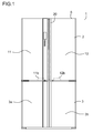
- Fig. 1 shows a front view showing a refrigerator that includes a door opening/closing mechanism according to a first embodiment of the present invention.
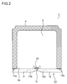
- Fig. 2 shows a top cross-sectional view showing the refrigerator that includes the door opening/closing mechanism.
- the refrigerator 1 is disposed with a refrigerating chamber 2 and a freezing chamber 3 separated in a main body portion 5.
- the refrigerator 1 is provided with a door opening/closing mechanism 10 having a first door 11 and a second door 12 that open and close a front opening portion 2a of the refrigerating chamber 2.
- a front opening portion (not shown) of the freezing chamber 3 is opened and closed by doors 3a, 3b.
- the first door 11 and the second door 12 cover both sides with respect to a center of the opening portion 2a, and rotatably supported by shaft portions 11a, 12a (pivotal shafts) at both ends of the opening portion 2a.
- a gap G is formed between the first door 11 and the second door 12 with both the first door 11 and the second door 12 closed. In this way, when opening and closing the first door 11 and the second door 12, interference between the first door 11 and th second door 12 is avoided.
- Lower end portions of the first door 11 and the second door 12 are provided with handles 11b, 12b, respectively.
- the handles 11b, 12b are respectively formed of concave portions recessed in lower surfaces of the first door 11 and th second door 12.
- the handles 11b, 12b are grasped, and the first door 11 and the second door 12 are swung left and right respectively to be opened.
- the swing partitioning body 20 is composed of a slender plate-shaped member extending in a vertical direction (shaft direction of the shaft portions 11a, 12a), and a length of the swing partitioning body 20 in the vertical direction is slightly shorter than a length of the refrigerating chamber 2 in the vertical direction.
- a heat insulating member (not shown) composed of, for example, foamed polystyrene is packed in the swing partitioning body 20. In this way, it is possible to improve heat insulating performance of the swing partitioning body 20.
- a lower portion of a rear portion of the refrigerator 1 is provided therein with a mechanical chamber (not shown) where a compressor (not shown) for driving a freezing cycle is disposed.
- the compressor is connected to a refrigerant pipe (not shown), and a refrigerant flows in the refrigerant pipe because of the driving of the freezing cycle.
- a cooler (not shown) disposed on a low temperature side of the freezing cycle and air perform a heat exchange with each other, whereby a cold air is generated. By the cold air, stored things in the refrigerating chamber 2 are refrigerated and preserved, and stored things in the freezing chamber 3 are frozen and preserved.
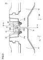
- Fig. 3 shows a top cross-sectional view of a main portion of the door opening/closing mechanism 10 of the refrigerator 1.
- Fig. 4 shows a cross-sectional view along an A-A line of Fig. 3 .
- the first door 11 is closed, and the swing partitioning body 20 is disposed at a closing position described later.
- the swing partitioning body 20 is axially supported by a hinge portion 23 disposed on a rear side of the first door 11, and swingable on a shaft parallel with the shaft portion 11a of the first door 11.
- the hinge portion 23 is disposed at an upper end portion and a lower end portion of the swing partitioning body 20.
- a concave portion 21 is recessed in the upper end portion of the swing partitioning body 20.
- a bottom surface of the concave portion 21 is provided with a coil spring (not shown).
- a protruding portion 22, which protrudes upward, is mounted on an upper end of the coil spring. In this way, the protruding portion 22 is biased upward. In other words, the protruding portion 22 is energized in a direction parallel with the shaft direction of the shaft portion 11 a of the first door 11.
- the protruding portion 22 is not especially limited in material and is formed of resin, for example.
- An upper portion of a front surface 22a of the protruding portion 22 has an inclined surface 221a that is inclined to come closer to a base 22c of the protruding portion 22 as the upper portion of the front surface 22a of the protruding portion 22 advances in an opening direction (arrow OP) of the first door 11.
- An upper portion of a rear surface 22b of the protruding portion 22 has an inclined surface 221b that is inclined to come closer to the base 22c of the protruding portion 22 as the first door 11 advances in a closing direction (arrow CL).
- a central portion of a front end portion of a ceiling surface 2b of the refrigerating chamber 2 is provided with a guide portion 30 that has a substantially rectangular parallelepiped shape.
- the guide portion 30 is formed of resin, for example, and disposed at a position to oppose the protruding portion 22 at a closing time of the first door 11.
- a lower portion of a front surface of the guide portion 30 is provided with an inclined surface 32 that is inclined to come closer to the base 22c of the protruding portion 22 as the lower portion of the front surface of the guide portion 30 advances in the closing direction (arrow CL) of the first door 11.
- a guide groove 31 is recessed in a bottom surface of guide portion 30 to extend left and right, and the guide groove 31 guides the protruding portion 22.
- the protruding portion 22 and the guide portion 30 compose a guide mechanism.
- Circumferential edge portions of rear surfaces of the first door 11 and second door 12 are provided with flexible packings 41a, 41b which include a magnet therein. With the aid of magnetic attraction, the first door 11 and the second door 12 tightly contacts a circumferential edge portion of the opening portion 2a formed of a magnetic material when the first door 11 and the second door 12 are closed. At this time, the packings 41a, 41b on the open sides of the first door 11 and the second door 12 tightly contact a front surface of the swing partitioning body 20.
- Fig. 5 shows a bottom surface of the guide portion 30.
- an upper side and lower side of the guide portion 30 indicate an outer side (front side of the refrigerator 1) of the refrigerating chamber 2 and an inner side of the refrigerating chamber 2, respectively.
- a first wall surface 31a and second wall surface 31b of the guide groove 31 opposing each other are each formed of a curved surface whose rear surface is bent convexly, and a plan shape of the guide grove 31 is a comma shape.
- one end portion 31c of the guide groove 31 is opened forward, and the other end portion 31d is closed.
- the protruding portion 22 enters the guide groove 31 from the one end portion 31 c.
- Fig. 6 shows a top cross-sectional view in a state where the first door 11 is closed
- Fig. 7 shows a top cross-sectional view in a state where the first door 11 is opened.
- the swing partitioning body 20 is disposed at the closing position that protrudes from a side end surface 11c of the first door 11.
- the front surface of the swing partitioning body 20 tightly contacts the packings 41a, 41b of the first door 11 and second door 12 (see Fig. 3 ). In this way, a cold air leak from the gap G between the first door 11 and the second door 12 is prevented.
- the protruding portion 22 of the swing partitioning body 20 Upon starting to open the first door 11 from the state in Fig. 6 by grasping the handle 11b, the protruding portion 22 of the swing partitioning body 20 is guided by the guide groove 31 of the guide portion 30. At this time, the front surface 22a of the protruding portion 22 contacts the first wall surface 31a (see Fig. 5 ) of the guide groove 31, and the protruding portion 22 slides toward the one end portion 31c (see Fig. 5 ) of the guide groove 31 along the first wall surface 31a. In this way, the swing partitioning body 20 swings counterclockwise on the hinge portion 23 in Fig. 6 .
- the swing partitioning body 20 is stopped. At this time, the swing partitioning body 20 is disposed at an opening position that is disposed on a plane substantially flush with the side end surface 11c of the first door 11 (see Fig. 7 ). In this way, interference between the swing partitioning body 20 and the second door 12 is avoided.
- the protruding portion 22 of the swing partitioning body 20 Upon closing the opened first door 11 (see Fig. 7 ), the protruding portion 22 of the swing partitioning body 20 enters the guide groove 31 from the one end portion 31c of the guide groove 31 of the guide portion 30. And, the rear surface 22b of the protruding portion 22 contacts the second wall surface 31b (see Fig. 5 ) of the guide groove 31, and the protruding portion 22 slides toward the other end portion 31d (see Fig. 5 ) of the guide groove 31 along the second wall surface 31b. In this way, the swing partitioning body 20 swings clockwise on the hinge portion 23 in Fig. 7 .
- the swing of the swing partitioning body 20 is stopped. In this way, the swing partitioning body 20 is disposed at the closing position that protrudes from the side end surface 11c of the first door 11. At this time, the first door 11 is closed. Besides, when the second door 12 is closed, the swing partitioning body 20 straddles the rear surfaces of the first door 11 and second door 12 (see Fig. 3 ). In this way, as described above, the cold air leak from the gap G is prevented.
- the protruding portion 22 counters the bias force to evacuate in a downward direction (the shaft direction, that is, a direction to leave the guide portion 30) as shown by an arrow D (see Fig. 4 ).
- the protruding portion 22 comes out of the guide groove 31, the first door 11 opens.
- the engagement between the protruding portion 22 and the guide groove 31 is disengaged, and the first door 11 opens. Accordingly, the user can open the first door 11 by grasping the swing partitioning body 20 without grasping the handle 11b of the first door 11. As a result of this, it is possible to improve the usability of the door opening/closing mechanism 10 of the refrigerator 1. Besides, it is possible to prevent breakage of the protruding portion 22 and guide portion 30.
- the inclined surface 221b of the protruding portion 22 is inclined to come closer to the base 22c of the protruding portion 22 as the inclined surface 221b of the protruding portion 22 advances in the closing direction (arrow CL) of the first door 11.
- the inclined surface 221b of the protruding portion 22 contacts the inclined surface 32 of the front surface of the guide portion 30, and the protruding portion 22 can counter the bias force to smoothly move in the shaft direction, that is, the direction to leave the guide portion 30. Accordingly, the user can close the first door 11 without disposing the swing partitioning body 20 on the plane substantially flush with the side end surface 11c of the first door 11. As a result of this, it is possible to improve the usability of the door opening/closing mechanism 10 of the refrigerator 1. Besides, it is possible to prevent the breakage of the protruding portion 22 and guide portion 30.
- the protruding portion 22 is biased in the shaft direction, and when the first door 11 whose swing partitioning body 20 is disposed at the closing positon is opened, the protruding portion 22 evacuates in the shaft direction upon colliding with the guide portion 30 with the force greater than the predetermined value. In this way, the user can open the first door 11 by grasping the swing partitioning body 20. Accordingly, it is possible to improve the usability of the door opening/closing mechanism 10 of the refrigerator 1. Besides, it is possible to prevent the breakage of the protruding portion 22 and guide portion 30.
- the surface of the protruding portion 22, which contacts the guide portion 30 when opening the first door 11 whose swing partitioning body 20 is disposed at the closing position, is composed of the inclined surface 221a. In this way, when the first door 11 is opened by grasping the swing partitioning body 20 located at the closing position, the protruding portion 22 can counter the bias force to smoothly move in the shaft direction, that is, the direction to leave the guide portion 30.
- the protruding portion 22 evacuates in the shaft direction upon colliding with the guide portion 30 with the force greater than the predetermined value. In this way, the user can close the first door 11 without disposing the swing partitioning body 20 on the plane substantially flush with the side end surface 11c of the first door 11. As a result of this, it is possible to improve the usability of the door opening/closing mechanism 10 of the refrigerator 1. Besides, it is possible to prevent the breakage of the protruding portion 22 and guide portion 30.
- the surface of the protruding portion 22, which contacts the guide portion 30 when closing the first door 11 whose swing partitioning body 20 is disposed at the closing position, is composed of the inclined surface 221b. In this way, when the first door 11 is closed with the swing partitioning body 20 kept at the closing position, the protruding portion 22 can counter the bias force to smoothly move in the shaft direction, that is, the direction to leave the guide portion 30.
- the protruding portion 22 and the guide portion 30 are disposed on the swing partitioning body 20 and the main body portion 5, respectively.
- the protruding portion 22 and the guide portion 30 may be disposed on the main body portion 5 and the swing partitioning body 20, respectively. Even in this case, the user can open the first door 11 by grasping the swing partitioning body 20. Accordingly, it is possible to improve the usability of the door opening/closing mechanism 10 of the refrigerator 1.
- both the protruding portion 22 and the guide portion 30 may be disposed to be biased in a direction (shaft direction) parallel with the direction of the shaft portion 11a (pivotal shaft) of the first door 11, to counter the bias force and evacuate in the shaft direction.
- the guide portion 30 may be disposed to be biased in the direction (shaft direction) parallel with the direction of the shaft portion 11a (pivotal shaft) of the first door 11, to counter the bias force and evacuate from the protruding portion 22 in the shaft direction, and the protruding portion 22 may be fixedly disposed on the swing partitioning body 20.
- the guide portion 30 may be disposed to be biased in the direction (shaft direction) parallel with the direction of the shaft portion 11a (pivotal shaft) of the first door 11, to counter the bias force and evacuate from the protruding portion 22 in the shaft direction, and the protruding portion 22 may be fixedly disposed on the swing partitioning body 20.
- the surface of the guide portion 30, which contacts the protruding portion 22 when opening the first door 11 whose swing partitioning body 20 is disposed at the closing position may be composed of an inclined surface.
- the inclined surface 221a on the front surface 22a of the protruding portion 22, and for example, the front surface 22a may be formed of a vertical surface.
- the inclined surface 32 is disposed on the front surface of the guide portion 30, but the front surface of the guide portion 30 may be formed of a vertical surface without disposing the inclined surface 32.
- the inclined surface 221b is disposed on the rear surface 22b of the protruding portion 22; accordingly, when closing the first door 11 whose swing partitioning body 20 is disposed at the closing positon, the protruding portion 22 can smoothly evacuate in the shaft direction upon colliding with the guide portion 30 with the force greater than the predetermined value.
- the inclined surface 32 is disposed on the front surface of the guide portion 30, it is unnecessary to dispose the inclined surface 221b on the rear surface 22b of the protruding portion 22, and the rear surface 22b may be formed of a vertical surface, for example.
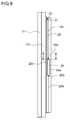
- Fig. 8 shows a side view of the first door 11 of the door opening/closing mechanism 10 of the refrigerator 1 according to the present embodiment, wherein the swing partitioning body 20 is disposed at the closing position.
- Fig. 9 is a cross-sectional view along a B-B line of Fig. 8 .
- the present embodiment is different from the first embodiment in that the swing partitioning body 20 is provided with an operation member 25 and a connection member 26. The other portions are the same as the first embodiment.
- the operation member 25 is disposed in a cutout portion 20b that is disposed at a center portion in a vertical direction of a rear surface 20a of the swing partitioning body 20.
- the operation member 25 has a plate-shaped member 25a and a shaft portion 25b.
- the plate-shaped member 25a and the shaft portion 25b are not limited in material, and are formed of resin, for example.
- the shaft portion 25b is disposed at an upper end portion and lower end portion of the plate-shaped member 25a, and the plate-shaped member 25a is structured to be able to swing on the shaft portion 25a in the same direction as the swing direction of the swing partitioning body 20.
- a distance between one end portion 251a of the plate-shaped member 25a and the shaft portion 25b is shorter than a distance between the other end portion 252a of the plate-shaped member 25a and the shaft portion 25b.
- the plate-shaped member 25a of the operation member 25 is biased by, for example, a coil spring or the like (not shown) in such a way that the other end portion 252a is situated forward than the one end portion 251a.
- connection member 26 connects the other end portion 252a of the operation member 25 and the protruding portion 22 to each other.
- the connection member 26 is not especially limited in material, and is formed of a metal wire or the like, for example.
- the connection member 26 is disposed in a space (not shown) that is formed in the heat insulating member of the swing partitioning body 20 and is slender in a vertical direction.
- a length of the connection member 26 is set in such a way that when the operation member 25 is operated, the protruding portion 22 moves in a downward direction (the shaft direction, that is, the direction to leave the guide portion 30) to be situated more downward than a lower surface 30a (see Fig. 4 ) of the guide portion 30.
- operating the operation member 25 is swinging the plate-shaped member 25a of the operation member 25 in such a way that the one end portion 251 moves forward.
- the user can open and close the first door 11 whose swing partitioning body 20 is disposed at the closing position.
- the plate-shaped member 25 of the operation member 25 swings in such a way that the one end portion 251a moves forward and the other end portion 252a moves backward.
- the protruding portion 22 moves in the downward direction (the shaft direction, that is, the direction to leave the guide portion 30) via the connection member 26.
- the protruding portion 22 can move in the shaft direction, that is, the direction to leave the guide portion 30 without contacting the guide portion 30. Accordingly, it is possible to reduce breakage and wear of the protruding portion 22 and guide portion 30 caused by contact. As a result of this, it is possible to achieve longevity of the door opening/closing mechanism 10 of the refrigerator 1.
- the protruding portion 22 is disposed on the swing partitioning body 20
- the guide portion 30 is disposed on the main body portion 5 (apparatus main body)
- the operation member 25, which is connected to the protruding portion 22 by the connection member 26, is disposed in the swing partitioning body 20
- the protruding portion 22 moves in the shaft direction, that is, the direction to leave the guide portion 30.
- the protruding portion 22 can easily come out of the guide groove 31 of the guide portion 30. Because of this, it is unnecessary to provide the front surface 22a and rear surface 22b of the protruding 22 with the inclined surfaces 221a, 221b of the first embodiment, and the front surface 22a and the rear surface 22b each may be formed of a vertical surface, for example. Accordingly, it is possible raise degree of freedom of designing the protruding portion 22.
- the swing partitioning body 20 may be provided with the guide portion 30, the main body portion 5 (apparatus main body) may be provided with the protruding portion 22, the swing partitioning body 20 may be provided with the operation member 25 that is connected to the guide portion 30 by the connection member 26, and when the operation member 25 is operated, the guide portion 30 may move in the shaft direction, that is, the direction to leave the protruding portion 22.
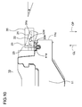
- Fig. 10 shows a top cross-sectional view in a state where the first door 11 of the door opening/closing mechanism 10 of the refrigerator 1 according to the present embodiment is closed, that is, shows a state where an end portion of the swing partitioning body 20 near the second poor 12 is drawn forward.
- the same portions as the first embodiment shown in Fig. 1 to Fig. 7 described above are indicated by the same reference numbers.
- the structure of the front surface 22a of the protruding portion 22 of the swing partitioning body 20 is different from the first embodiment. The other portions are the same as the first embodiment.
- the front surface 22a of the protruding portion 22 only a front surface of an end portion 22d near the second door 12 is formed of an inclined surface that is inclined to come closer to the base 22c (see Fig. 4 ) of the protruding portion 22 as only the front surface of the end portion 22d near the second door 12 advances in the opening direction (arrow OP) of the first door 11.
- the other portions of the front surface 22a of the protruding portion 22 are each formed of a vertical surface.
- the user grasps the swing partitioning body 20 located at the closing position and swings forward the swing partitioning body 20 at a predetermined angle ⁇ to the closing position.
- the front surface of the end portion 22d of the protruding portion 22 contacts the first wall surface 31a of the guide groove 31.
- the protruding portion 22 counters the bias force to move in the downward direction (the shaft direction, that is, the direction to leave the guide portion 30). In this way, the first door 11 opens.
- the present embodiment it is possible to obtain the same effects as the first embodiment.
- the front surface 22a of the protruding portion 22 only the front surface of the end portion 22d near the second door 12 is formed of the inclined surface that is inclined to come closer to the base 22c of the protruding portion 22 as only the front surface of the end portion 22d near the second door 12 advances in the opening direction (arrow OP) of the first door 11, and the other portions of the front surface 22a of the protruding portion 22 are each formed of the vertical surface.
- the swing partitioning body 20 may be provided with the operation member 25 and connection member 26 of the second embodiment, and when the operation member 25 is operated, the protruding portion 22 may move in the shaft direction, that is, the direction to leave the guide portion 30.
- the guide portion 30 has the guide groove 31, but in place of the guide portion 30 having the guide groove 31, for example, two protruding walls, which are disposed away from each other by a predetermined interval in a front-rear direction and formed independently of each other, may compose a guide portion, and the guide portion may guide the protruding portion 22.
- the hinge portion 23 may be provided with a torsion coil spring that biases the swing partitioning body 20 in the direction to swing from the closing position to the opening position. In this way, when opening the first door 11, it is possible to surely dispose the swing partitioning body 20 at the opening position. Accordingly, it is possible to surely prevent the interference between the second door 12 and the swing partitioning body 20.
- the hinge portion 23 may be provided with a torsion coil spring that biases the swing partitioning body 20 in the direction to swing from the opening position to the closing position.
- a torsion coil spring that biases the swing partitioning body 20 in the direction to swing from the opening position to the closing position.
- the refrigerator 1 including the door opening/closing mechanism 10 is described, but the door opening/closing mechanism 10 may be disposed in other apparatuses.
- the first door 11 and the second door 12 are disposed left and right, respectively, but may be disposed in a vertical direction or in a front-rear direction.
- the present invention is applicable to a door opening/closing mechanism having first and second doors that cover both sides with respect to a center of an opening portion, and to a refrigerator that includes the door opening/closing mechanism.
Landscapes
- Engineering & Computer Science (AREA)
- Chemical & Material Sciences (AREA)
- Combustion & Propulsion (AREA)
- Physics & Mathematics (AREA)
- Mechanical Engineering (AREA)
- Thermal Sciences (AREA)
- General Engineering & Computer Science (AREA)
- Refrigerator Housings (AREA)
Abstract
Description
- The present invention relates to a door opening/closing mechanism having a first door and a second door that cover both sides with respect to a center of an opening portion and to a refrigerator that includes the door opening/closing mechanism.
- A patent literature 1 discloses a refrigerator that includes a door opening/closing mechanism which has a first door and a second door for covering both sides with respect to a center of an opening portion. This refrigerator includes a main body portion that has a refrigerating chamber and is provided with the door opening/closing mechanism having the first door and the second door that open and close the opening portion of a front surface of the refrigerating chamber.
- The first door and the second door cover both sides with respect to the center of the opening portion and are rotatably supported respectively by pivotal shafts at both ends of the opening portion. A gap for preventing interference at opening/closing times is formed between the first door and the second door with both the first door and the second door closed. The first door and the second door are respectively provided with handles at end portions on sides of the first door and the second door close to each other. When a user grasps the handles and draws the first door and the second door toward the user, the first door and the second door are swung and opened left and right, respectively.
- An open end of the first door is provided with a plate-shaped swing partitioning body that extends slenderly in a vertical direction. The swing partitioning body is axially supported by a support portion disposed on a rear side of the first door and rotatable on a shaft parallel with a pivotal shaft of the first door.
- A protruding portion is disposed fixedly on an upper end surface of the swing partitioning body. Besides, a guide portion for guiding the protruding portion is disposed fixedly on a central portion of a front end portion of a ceiling surface of the refrigerating chamber. When the protruding portion is guided by the guide portion because of the opening/closing operation of the first door, the swing partitioning body swings associating with the opening/closing operation of the first door.
- In the refrigerator including the door opening/closing mechanism having the above structure, at the closing time of the first door, the swing partitioning body is disposed at a closing position that protrudes from the side end surface of the first door. When the closed first door is opened, the protruding portion is guided by the guide portion and the swing partitioning body swings. In this way, at the opening time of the first door, the swing partitioning body is disposed on a plane substantially flush with the side end surface of the first door. Accordingly, interference between the swing partitioning body and the second door is avoided.
- When the opened first door is closed, the protruding portion is guided by the guide portion and the swing partitioning body swings. In this way, the swing partitioning body is disposed at the closing position. At this time, when the second door is closed, the swing partitioning body straddles the rear surfaces of the first door and second door. In this way, a cold air leak through the gap between the first door and the second door is prevented.
- PLT1:
JP-A-2009-250602 pages 4, 5, andFigs. 3 ,4 ) - According to the refrigerator including the conventional door opening/closing mechanism, when the second door is opened with the first door closed, there is a case where the user attempts to open the first door by grasping the swing partitioning body. Especially, in a case where the user attempts to open the closed first door while opening the second door and looking in the refrigerator chamber, chances that the swing partitioning body is grasped increase more.
- However, even if the user grasps the swing partitioning body and draws the first door, the protruding portion cannot come out of the guide portion because the protruding portion hooks on to the guide portion. Because of this, the user cannot open the first door by grasping the swing partitioning body. At this time, if the first door is drawn with greater force, the protruding portion or the guide portion is likely to be broken.
- Because of this, it is necessary for the user to let go his/her hold of the swing partitioning body and grasp the handle of the first door when opening the first door. Accordingly, there is a problem that usability of the door opening/closing mechanism is undermined.
- It is an object of the present invention to provide a door opening/closing mechanism whose usability is able to be improved and a refrigerator that includes the door opening/closing mechanism.
- To achieve the above object, a door opening/closing mechanism according to the present invention includes: a first door and a second door that cover both sides with respect to a center of an opening portion of an apparatus main body and are rotatably supported respectively at both end portions of the opening portion; a swing partitioning body that is swingably disposed at an open end of the first door; and a guide mechanism that guides swingably the swing partitioning body and is disposed at a closing position to protrude from a side end surface of the first door at a closing time of the first door, and is disposed on a plane substantially flush with the side end surface of the first door at an opening time of the first door; wherein the guide mechanism has a protruding portion disposed on one of the apparatus main body and the swing partitioning body and a guide portion that is disposed on other one of the apparatus main body and the swing partitioning body to guide the protruding portion; and the one of the protruding portion and the guide portion is biased in a shaft direction, and evacuates in the shaft direction upon colliding with the other one with force greater than a predetermined value when the first door the swing partitioning body of which is disposed at the closing position is opened.
- According to this structure, the guide mechanism has: the protruding portion disposed on the one of the apparatus main body and the swing partitioning body; and the guide portion that is disposed on the other one of the apparatus main body and the swing partitioning body to guide the protruding portion, and the one of the protruding portion and the guide portion is biased in the shaft direction. At the closing time of the first door, the swing partitioning body is disposed at the closing position to protrude from the side end surface of the first door. When the closed first door is opened, the protruding portion is guided by the guide portion and the swing partitioning body swings on a shaft parallel with a pivotal shaft of the first door. In this way, at the opening time of the first door, the swing partitioning body is disposed on the plane substantially flush with the side end surface of the first door. And, the one of the protruding portion and the guide portion evacuates in the shaft direction upon colliding with the other one with the force greater than the predetermined value when the first door the swing partitioning body of which is disposed at the closing position is opened. In this way, the user can open the first door by grasping the swing partitioning body located at the closing position.
- Besides, in the present invention, it is preferable that one of surfaces of the guide portion and protruding portion, which contact each other when opening the first door the swing partitioning body of which is disposed at the closing positon, is composed of an inclined surface. According to this structure, the one of the protruding portion and the guide portion moves along the inclined surface upon colliding with the other one with the force greater than the predetermined value when the first door the swing partitioning body of which is disposed at the closing position is opened.
- Besides, in the present invention, it is preferable that when closing the first door the swing partitioning body of which is disposed at the closing positon, the one of the protruding portion and the guide portion evacuates in the shaft direction upon colliding with the other one with the force greater than the predetermined value. According to this structure, it is possible to close the first door whose swing partitioning body is disposed at the closing position.
- Besides, in the present invention, it is preferable that one of the surfaces of the guide portion and protruding portion, which contact each other when closing the first door the swing partitioning body of which is disposed at the closing positon, is formed of an inclined surface. According to this structure, the one of the guide portion and the protruding portion moves along the inclined surface upon colliding with the other one with the force greater than the predetermined value when the first door whose swing partitioning body is disposed at the closing position is closed.
- Besides, a refrigerator according to the present invention includes the door opening/closing mechanism having the above structure.
- According to the present invention, the one of the protruding portion and the guide portion is biased in the shaft direction, and evacuates in the shaft direction upon colliding with the other one with the force greater than the predetermined value when the first door whose swing partitioning body is disposed at the closing position is opened. In this way, the user can open the first door by grasping the swing partitioning body. Accordingly, it is possible to improve the usability of the door opening/closing mechanism.
-
- [
Fig. 1 ] is a front view showing a refrigerator that includes a door opening/closing mechanism according to a first embodiment of the present invention. - [
Fig. 2 ] is a top cross-sectional view showing the refrigerator that includes the door opening/closing mechanism according to the first embodiment of the present invention. - [
Fig. 3 ] is a top cross-sectional view showing a main portion of the door opening/closing mechanism according to the first embodiment of the present invention. - [
Fig. 4 ] is a cross-sectional view along an A-A line ofFig. 3 . - [
Fig. 5 ] is a bottom surface of a guide portion of the door opening/closing mechanism according to the first embodiment of the present invention. - [
Fig. 6 ] is a top cross-sectional view showing a state in which a first door of the door opening/closing mechanism according to the first embodiment of the present invention is closed. - [
Fig. 7 ] is a top cross-sectional view showing a state in which the first door of the door opening/closing mechanism according to the first embodiment of the present invention is opened. - [
Fig. 8 ] is a side view of a first door of a door opening/closing mechanism according to a second embodiment of the present invention. - [
Fig. 9 ] is a cross-sectional view along a B-B line ofFig. 8 . - [
Fig. 10 ] is a top cross-sectional view showing a state in which an end portion of a swing partitioning body near a second door is drawn forward with a first door of a door opening/closing mechanism according to a third embodiment of the present invention closed. - Hereinafter, embodiments of the present invention are described with reference to the drawings.
Fig. 1 shows a front view showing a refrigerator that includes a door opening/closing mechanism according to a first embodiment of the present invention.Fig. 2 shows a top cross-sectional view showing the refrigerator that includes the door opening/closing mechanism. The refrigerator 1 is disposed with a refrigeratingchamber 2 and a freezingchamber 3 separated in amain body portion 5. Besides, the refrigerator 1 is provided with a door opening/closing mechanism 10 having afirst door 11 and asecond door 12 that open and close afront opening portion 2a of the refrigeratingchamber 2. A front opening portion (not shown) of the freezingchamber 3 is opened and closed bydoors 3a, 3b. - The
first door 11 and thesecond door 12 cover both sides with respect to a center of theopening portion 2a, and rotatably supported byshaft portions opening portion 2a. A gap G is formed between thefirst door 11 and thesecond door 12 with both thefirst door 11 and thesecond door 12 closed. In this way, when opening and closing thefirst door 11 and thesecond door 12, interference between thefirst door 11 and thsecond door 12 is avoided. - Lower end portions of the
first door 11 and thesecond door 12 are provided withhandles handles first door 11 and thsecond door 12. Thehandles first door 11 and thesecond door 12 are swung left and right respectively to be opened. - An end portion (end portion on the open side of the first door 11) of the
first door 11 near thesecond door 12 is provided with aswing partitioning body 20. Theswing partitioning body 20 is composed of a slender plate-shaped member extending in a vertical direction (shaft direction of theshaft portions swing partitioning body 20 in the vertical direction is slightly shorter than a length of the refrigeratingchamber 2 in the vertical direction. Besides, a heat insulating member (not shown) composed of, for example, foamed polystyrene is packed in theswing partitioning body 20. In this way, it is possible to improve heat insulating performance of theswing partitioning body 20. - A lower portion of a rear portion of the refrigerator 1 is provided therein with a mechanical chamber (not shown) where a compressor (not shown) for driving a freezing cycle is disposed. The compressor is connected to a refrigerant pipe (not shown), and a refrigerant flows in the refrigerant pipe because of the driving of the freezing cycle. A cooler (not shown) disposed on a low temperature side of the freezing cycle and air perform a heat exchange with each other, whereby a cold air is generated. By the cold air, stored things in the refrigerating
chamber 2 are refrigerated and preserved, and stored things in the freezingchamber 3 are frozen and preserved. -
Fig. 3 shows a top cross-sectional view of a main portion of the door opening/closing mechanism 10 of the refrigerator 1.Fig. 4 shows a cross-sectional view along an A-A line ofFig. 3 . InFig. 3 andFig. 4 , thefirst door 11 is closed, and theswing partitioning body 20 is disposed at a closing position described later. Theswing partitioning body 20 is axially supported by ahinge portion 23 disposed on a rear side of thefirst door 11, and swingable on a shaft parallel with theshaft portion 11a of thefirst door 11. Thehinge portion 23 is disposed at an upper end portion and a lower end portion of theswing partitioning body 20. - A
concave portion 21 is recessed in the upper end portion of theswing partitioning body 20. A bottom surface of theconcave portion 21 is provided with a coil spring (not shown). A protrudingportion 22, which protrudes upward, is mounted on an upper end of the coil spring. In this way, the protrudingportion 22 is biased upward. In other words, the protrudingportion 22 is energized in a direction parallel with the shaft direction of theshaft portion 11 a of thefirst door 11. The protrudingportion 22 is not especially limited in material and is formed of resin, for example. - An upper portion of a
front surface 22a of the protrudingportion 22 has aninclined surface 221a that is inclined to come closer to abase 22c of the protrudingportion 22 as the upper portion of thefront surface 22a of the protrudingportion 22 advances in an opening direction (arrow OP) of thefirst door 11. Besides, An upper portion of arear surface 22b of the protrudingportion 22 has aninclined surface 221b that is inclined to come closer to thebase 22c of the protrudingportion 22 as thefirst door 11 advances in a closing direction (arrow CL). - A central portion of a front end portion of a
ceiling surface 2b of the refrigeratingchamber 2 is provided with aguide portion 30 that has a substantially rectangular parallelepiped shape. Theguide portion 30 is formed of resin, for example, and disposed at a position to oppose the protrudingportion 22 at a closing time of thefirst door 11. A lower portion of a front surface of theguide portion 30 is provided with aninclined surface 32 that is inclined to come closer to thebase 22c of the protrudingportion 22 as the lower portion of the front surface of theguide portion 30 advances in the closing direction (arrow CL) of thefirst door 11. Aguide groove 31 is recessed in a bottom surface ofguide portion 30 to extend left and right, and theguide groove 31 guides the protrudingportion 22. The protrudingportion 22 and theguide portion 30 compose a guide mechanism. - Circumferential edge portions of rear surfaces of the
first door 11 andsecond door 12 are provided withflexible packings first door 11 and thesecond door 12 tightly contacts a circumferential edge portion of theopening portion 2a formed of a magnetic material when thefirst door 11 and thesecond door 12 are closed. At this time, thepackings first door 11 and thesecond door 12 tightly contact a front surface of theswing partitioning body 20. -
Fig. 5 shows a bottom surface of theguide portion 30. InFig. 5 , an upper side and lower side of theguide portion 30 indicate an outer side (front side of the refrigerator 1) of the refrigeratingchamber 2 and an inner side of the refrigeratingchamber 2, respectively. Afirst wall surface 31a andsecond wall surface 31b of theguide groove 31 opposing each other are each formed of a curved surface whose rear surface is bent convexly, and a plan shape of theguide grove 31 is a comma shape. Besides, oneend portion 31c of theguide groove 31 is opened forward, and theother end portion 31d is closed. The protrudingportion 22 enters theguide groove 31 from the oneend portion 31 c. -
Fig. 6 shows a top cross-sectional view in a state where thefirst door 11 is closed, andFig. 7 shows a top cross-sectional view in a state where thefirst door 11 is opened. In the door opening/closing mechanism 10 of the refrigerator 1 having the above structure, at the closing time of thefirst door 11, theswing partitioning body 20 is disposed at the closing position that protrudes from aside end surface 11c of thefirst door 11. At this time, upon closing thesecond door 12, the front surface of theswing partitioning body 20 tightly contacts thepackings first door 11 and second door 12 (seeFig. 3 ). In this way, a cold air leak from the gap G between thefirst door 11 and thesecond door 12 is prevented. - Upon starting to open the
first door 11 from the state inFig. 6 by grasping thehandle 11b, the protrudingportion 22 of theswing partitioning body 20 is guided by theguide groove 31 of theguide portion 30. At this time, thefront surface 22a of the protrudingportion 22 contacts thefirst wall surface 31a (seeFig. 5 ) of theguide groove 31, and the protrudingportion 22 slides toward the oneend portion 31c (seeFig. 5 ) of theguide groove 31 along thefirst wall surface 31a. In this way, theswing partitioning body 20 swings counterclockwise on thehinge portion 23 inFig. 6 . - Thereafter, when the protruding
portion 22 comes out of theguide groove 31 via the oneend portion 31c of theguide groove 31, the swing of theswing partitioning body 20 is stopped. At this time, theswing partitioning body 20 is disposed at an opening position that is disposed on a plane substantially flush with theside end surface 11c of the first door 11 (seeFig. 7 ). In this way, interference between theswing partitioning body 20 and thesecond door 12 is avoided. - Upon closing the opened first door 11 (see
Fig. 7 ), the protrudingportion 22 of theswing partitioning body 20 enters theguide groove 31 from the oneend portion 31c of theguide groove 31 of theguide portion 30. And, therear surface 22b of the protrudingportion 22 contacts thesecond wall surface 31b (seeFig. 5 ) of theguide groove 31, and the protrudingportion 22 slides toward theother end portion 31d (seeFig. 5 ) of theguide groove 31 along thesecond wall surface 31b. In this way, theswing partitioning body 20 swings clockwise on thehinge portion 23 inFig. 7 . - Thereafter, when the front surface of the protruding
portion 22 contacts thepacking 41a of thefirst door 11, the swing of theswing partitioning body 20 is stopped. In this way, theswing partitioning body 20 is disposed at the closing position that protrudes from theside end surface 11c of thefirst door 11. At this time, thefirst door 11 is closed. Besides, when thesecond door 12 is closed, theswing partitioning body 20 straddles the rear surfaces of thefirst door 11 and second door 12 (seeFig. 3 ). In this way, as described above, the cold air leak from the gap G is prevented. - When the
first door 11 whoseswing partitioning body 20 is disposed at the closing position is opened and the protrudingportion 22 collides with theguide portion 30 with force greater than a predetermined value, the protrudingportion 22 counters the bias force to evacuate in a downward direction (the shaft direction, that is, a direction to leave the guide portion 30) as shown by an arrow D (seeFig. 4 ). In this way, because the protrudingportion 22 comes out of theguide groove 31, thefirst door 11 opens. In other words, the engagement between the protrudingportion 22 and theguide groove 31 is disengaged, and thefirst door 11 opens. Accordingly, the user can open thefirst door 11 by grasping theswing partitioning body 20 without grasping thehandle 11b of thefirst door 11. As a result of this, it is possible to improve the usability of the door opening/closing mechanism 10 of the refrigerator 1. Besides, it is possible to prevent breakage of the protrudingportion 22 andguide portion 30. - Besides, the
inclined surface 221b of the protrudingportion 22 is inclined to come closer to thebase 22c of the protrudingportion 22 as theinclined surface 221b of the protrudingportion 22 advances in the closing direction (arrow CL) of thefirst door 11. In this way, when closing thefirst door 11 whoseswing partitioning body 20 is disposed at the closing position, theinclined surface 221b of the protrudingportion 22 contacts theinclined surface 32 of the front surface of theguide portion 30, and the protrudingportion 22 can counter the bias force to smoothly move in the shaft direction, that is, the direction to leave theguide portion 30. Accordingly, the user can close thefirst door 11 without disposing theswing partitioning body 20 on the plane substantially flush with theside end surface 11c of thefirst door 11. As a result of this, it is possible to improve the usability of the door opening/closing mechanism 10 of the refrigerator 1. Besides, it is possible to prevent the breakage of the protrudingportion 22 andguide portion 30. - According to the present embodiment, the protruding
portion 22 is biased in the shaft direction, and when thefirst door 11 whoseswing partitioning body 20 is disposed at the closing positon is opened, the protrudingportion 22 evacuates in the shaft direction upon colliding with theguide portion 30 with the force greater than the predetermined value. In this way, the user can open thefirst door 11 by grasping theswing partitioning body 20. Accordingly, it is possible to improve the usability of the door opening/closing mechanism 10 of the refrigerator 1. Besides, it is possible to prevent the breakage of the protrudingportion 22 andguide portion 30. - Besides, the surface of the protruding
portion 22, which contacts theguide portion 30 when opening thefirst door 11 whoseswing partitioning body 20 is disposed at the closing position, is composed of theinclined surface 221a. In this way, when thefirst door 11 is opened by grasping theswing partitioning body 20 located at the closing position, the protrudingportion 22 can counter the bias force to smoothly move in the shaft direction, that is, the direction to leave theguide portion 30. - Besides, when closing the
first door 11 whoseswing partitioning body 20 is disposed at the closing position, the protrudingportion 22 evacuates in the shaft direction upon colliding with theguide portion 30 with the force greater than the predetermined value. In this way, the user can close thefirst door 11 without disposing theswing partitioning body 20 on the plane substantially flush with theside end surface 11c of thefirst door 11. As a result of this, it is possible to improve the usability of the door opening/closing mechanism 10 of the refrigerator 1. Besides, it is possible to prevent the breakage of the protrudingportion 22 andguide portion 30. - Besides, the surface of the protruding
portion 22, which contacts theguide portion 30 when closing thefirst door 11 whoseswing partitioning body 20 is disposed at the closing position, is composed of theinclined surface 221b. In this way, when thefirst door 11 is closed with theswing partitioning body 20 kept at the closing position, the protrudingportion 22 can counter the bias force to smoothly move in the shaft direction, that is, the direction to leave theguide portion 30. - In the meantime, in the present embodiment, the protruding
portion 22 and theguide portion 30 are disposed on theswing partitioning body 20 and themain body portion 5, respectively. However, the protrudingportion 22 and theguide portion 30 may be disposed on themain body portion 5 and theswing partitioning body 20, respectively. Even in this case, the user can open thefirst door 11 by grasping theswing partitioning body 20. Accordingly, it is possible to improve the usability of the door opening/closing mechanism 10 of the refrigerator 1. - Besides, in the present embodiment, both the protruding
portion 22 and theguide portion 30 may be disposed to be biased in a direction (shaft direction) parallel with the direction of theshaft portion 11a (pivotal shaft) of thefirst door 11, to counter the bias force and evacuate in the shaft direction. - Besides, in the present embodiment, the
guide portion 30 may be disposed to be biased in the direction (shaft direction) parallel with the direction of theshaft portion 11a (pivotal shaft) of thefirst door 11, to counter the bias force and evacuate from the protrudingportion 22 in the shaft direction, and the protrudingportion 22 may be fixedly disposed on theswing partitioning body 20. In this way, it becomes unnecessary to dispose theconcave portion 21 on theswing partitioning body 20, and it is possible to sufficiently pack the heat insulating member into theswing partitioning body 20. Accordingly, it is possible to improve the heat insulating performance of theswing partitioning body 20. - Besides, the surface of the
guide portion 30, which contacts the protrudingportion 22 when opening thefirst door 11 whoseswing partitioning body 20 is disposed at the closing position, may be composed of an inclined surface. In this case, it is unnecessary to dispose theinclined surface 221a on thefront surface 22a of the protrudingportion 22, and for example, thefront surface 22a may be formed of a vertical surface. - Besides, in the present embodiment, the
inclined surface 32 is disposed on the front surface of theguide portion 30, but the front surface of theguide portion 30 may be formed of a vertical surface without disposing theinclined surface 32. Even in this case, theinclined surface 221b is disposed on therear surface 22b of the protrudingportion 22; accordingly, when closing thefirst door 11 whoseswing partitioning body 20 is disposed at the closing positon, the protrudingportion 22 can smoothly evacuate in the shaft direction upon colliding with theguide portion 30 with the force greater than the predetermined value. - Besides, if the
inclined surface 32 is disposed on the front surface of theguide portion 30, it is unnecessary to dispose theinclined surface 221b on therear surface 22b of the protrudingportion 22, and therear surface 22b may be formed of a vertical surface, for example. - Next, a second embodiment of the present invention is described.
Fig. 8 shows a side view of thefirst door 11 of the door opening/closing mechanism 10 of the refrigerator 1 according to the present embodiment, wherein theswing partitioning body 20 is disposed at the closing position.Fig. 9 is a cross-sectional view along a B-B line ofFig. 8 . For the sake of description, the same portions as the first embodiment shown inFig. 1 to Fig. 7 described above are indicated by the same reference numbers. The present embodiment is different from the first embodiment in that theswing partitioning body 20 is provided with anoperation member 25 and aconnection member 26. The other portions are the same as the first embodiment. - The
operation member 25 is disposed in acutout portion 20b that is disposed at a center portion in a vertical direction of arear surface 20a of theswing partitioning body 20. Theoperation member 25 has a plate-shapedmember 25a and ashaft portion 25b. The plate-shapedmember 25a and theshaft portion 25b are not limited in material, and are formed of resin, for example. Theshaft portion 25b is disposed at an upper end portion and lower end portion of the plate-shapedmember 25a, and the plate-shapedmember 25a is structured to be able to swing on theshaft portion 25a in the same direction as the swing direction of theswing partitioning body 20. A distance between oneend portion 251a of the plate-shapedmember 25a and theshaft portion 25b is shorter than a distance between theother end portion 252a of the plate-shapedmember 25a and theshaft portion 25b. The plate-shapedmember 25a of theoperation member 25 is biased by, for example, a coil spring or the like (not shown) in such a way that theother end portion 252a is situated forward than the oneend portion 251a. - The
connection member 26 connects theother end portion 252a of theoperation member 25 and the protrudingportion 22 to each other. Theconnection member 26 is not especially limited in material, and is formed of a metal wire or the like, for example. Theconnection member 26 is disposed in a space (not shown) that is formed in the heat insulating member of theswing partitioning body 20 and is slender in a vertical direction. A length of theconnection member 26 is set in such a way that when theoperation member 25 is operated, the protrudingportion 22 moves in a downward direction (the shaft direction, that is, the direction to leave the guide portion 30) to be situated more downward than alower surface 30a (seeFig. 4 ) of theguide portion 30. In the meantime, operating theoperation member 25 is swinging the plate-shapedmember 25a of theoperation member 25 in such a way that the one end portion 251 moves forward. - Also in the door opening/
closing mechanism 10 of the refrigerator 1 having the above structure, in the same way as the first embodiment, the user can open and close thefirst door 11 whoseswing partitioning body 20 is disposed at the closing position. - Here, at the closing time of the
first door 11, if the user grasps theswing partitioning body 20 while pushing forward the oneend portion 251a of theoperation member 25, the plate-shapedmember 25 of theoperation member 25 swings in such a way that the oneend portion 251a moves forward and theother end portion 252a moves backward. In this way, the protrudingportion 22 moves in the downward direction (the shaft direction, that is, the direction to leave the guide portion 30) via theconnection member 26. In this way, when opening thefirst door 11 by grasping theswing partitioning body 20, the protrudingportion 22 can move in the shaft direction, that is, the direction to leave theguide portion 30 without contacting theguide portion 30. Accordingly, it is possible to reduce breakage and wear of the protrudingportion 22 andguide portion 30 caused by contact. As a result of this, it is possible to achieve longevity of the door opening/closing mechanism 10 of the refrigerator 1. - According to the present embodiment, it is possible to obtain the same effects as the first embodiment. Besides, the protruding
portion 22 is disposed on theswing partitioning body 20, theguide portion 30 is disposed on the main body portion 5 (apparatus main body), theoperation member 25, which is connected to the protrudingportion 22 by theconnection member 26, is disposed in theswing partitioning body 20, and when theoperation member 25 is operated, the protrudingportion 22 moves in the shaft direction, that is, the direction to leave theguide portion 30. In this way, when opening thefirst door 11 by grasping theswing partitioning body 20, it is possible to force the protrudingportion 22 to move in the shaft direction, that is, the direction to leave theguide portion 30 without forcing the protrudingportion 22 to contact theguide portion 30. Accordingly, it is possible to prevent the breakage and wear of the protrudingportion 22 andguide portion 30 caused by contact. As a result of this, it is possible to achieve the longevity of the door opening/closing mechanism 10. - Besides, by operating the
operation member 25, the protrudingportion 22 can easily come out of theguide groove 31 of theguide portion 30. Because of this, it is unnecessary to provide thefront surface 22a andrear surface 22b of the protruding 22 with theinclined surfaces front surface 22a and therear surface 22b each may be formed of a vertical surface, for example. Accordingly, it is possible raise degree of freedom of designing the protrudingportion 22. - In the meantime, in the second embodiment, the
swing partitioning body 20 may be provided with theguide portion 30, the main body portion 5 (apparatus main body) may be provided with the protrudingportion 22, theswing partitioning body 20 may be provided with theoperation member 25 that is connected to theguide portion 30 by theconnection member 26, and when theoperation member 25 is operated, theguide portion 30 may move in the shaft direction, that is, the direction to leave the protrudingportion 22. - Next, a third embodiment of the present invention is described.
Fig. 10 shows a top cross-sectional view in a state where thefirst door 11 of the door opening/closing mechanism 10 of the refrigerator 1 according to the present embodiment is closed, that is, shows a state where an end portion of theswing partitioning body 20 near the second poor 12 is drawn forward. For the sake of description, the same portions as the first embodiment shown inFig. 1 to Fig. 7 described above are indicated by the same reference numbers. In the present embodiment, the structure of thefront surface 22a of the protrudingportion 22 of theswing partitioning body 20 is different from the first embodiment. The other portions are the same as the first embodiment. - As to the
front surface 22a of the protrudingportion 22, only a front surface of anend portion 22d near thesecond door 12 is formed of an inclined surface that is inclined to come closer to thebase 22c (seeFig. 4 ) of the protrudingportion 22 as only the front surface of theend portion 22d near thesecond door 12 advances in the opening direction (arrow OP) of thefirst door 11. On the other hand, the other portions of thefront surface 22a of the protrudingportion 22 are each formed of a vertical surface. - In the door opening/
closing mechanism 10 of the refrigerator 1 having the above structure, in the closing state of the first door, the user grasps theswing partitioning body 20 located at the closing position and swings forward theswing partitioning body 20 at a predetermined angle θ to the closing position. At this time, the front surface of theend portion 22d of the protrudingportion 22 contacts thefirst wall surface 31a of theguide groove 31. Thereafter, when opening thefirst door 11 by grasping theswing partitioning body 20, if theend portion 22d of the protrudingportion 22 collides with theguide portion 30 with force greater than a predetermined value, the protrudingportion 22 counters the bias force to move in the downward direction (the shaft direction, that is, the direction to leave the guide portion 30). In this way, thefirst door 11 opens. - In the meantime, in a case where the forward swing angle of the
swing partitioning body 20 with respect to the closing position is under the predetermined angle θ, the inclined surface of theend portion 22d of the protrudingportion 22 does not contact thefirst wall surface 31 a of theguide groove 31. Because of this, for example, even in a case where a stored thing taken out from therefrigerator 2 collides with theswing partitioning body 20 located at the closing position, it is possible to reduce the opening of thefirst door 11 unexpected to the user. - In the meantime, the operation of closing the
first door 11 whoseswing partitioning body 20 is disposed at the closing position becomes the same operation as the first embodiment. - According to the present embodiment, it is possible to obtain the same effects as the first embodiment. Besides, as to the
front surface 22a of the protrudingportion 22, only the front surface of theend portion 22d near thesecond door 12 is formed of the inclined surface that is inclined to come closer to thebase 22c of the protrudingportion 22 as only the front surface of theend portion 22d near thesecond door 12 advances in the opening direction (arrow OP) of thefirst door 11, and the other portions of thefront surface 22a of the protrudingportion 22 are each formed of the vertical surface. In this way, for example, even in the case where a stored thing taken out from therefrigerator 2 collides with theswing partitioning body 20 located at the closing position, it is possible to reduce the opening of thefirst door 11 unexpected to the user. - In the meantime, in the third embodiment, the
swing partitioning body 20 may be provided with theoperation member 25 andconnection member 26 of the second embodiment, and when theoperation member 25 is operated, the protrudingportion 22 may move in the shaft direction, that is, the direction to leave theguide portion 30. - Besides, in the first to third embodiments, it is described that the
guide portion 30 has theguide groove 31, but in place of theguide portion 30 having theguide groove 31, for example, two protruding walls, which are disposed away from each other by a predetermined interval in a front-rear direction and formed independently of each other, may compose a guide portion, and the guide portion may guide the protrudingportion 22. - Besides, in the first to third embodiments, the
hinge portion 23 may be provided with a torsion coil spring that biases theswing partitioning body 20 in the direction to swing from the closing position to the opening position. In this way, when opening thefirst door 11, it is possible to surely dispose theswing partitioning body 20 at the opening position. Accordingly, it is possible to surely prevent the interference between thesecond door 12 and theswing partitioning body 20. - Besides, in the first to third embodiments, also the
hinge portion 23 may be provided with a torsion coil spring that biases theswing partitioning body 20 in the direction to swing from the opening position to the closing position. In this way, when closing thefirst door 11 and thesecond door 12, it is possible to force theswing partitioning body 20 to tightly contact thepackings first door 11 and thesecond door 12. - In the first to third embodiments, the refrigerator 1 including the door opening/
closing mechanism 10 is described, but the door opening/closing mechanism 10 may be disposed in other apparatuses. Besides, thefirst door 11 and thesecond door 12 are disposed left and right, respectively, but may be disposed in a vertical direction or in a front-rear direction. - The present invention is applicable to a door opening/closing mechanism having first and second doors that cover both sides with respect to a center of an opening portion, and to a refrigerator that includes the door opening/closing mechanism.
-
- 1
- refrigerator
- 2
- refrigerating chamber
- 2a
- opening portion
- 2b
- ceiling surface
- 3
- freezing chamber
- 3a
- door
- 5
- main body portion
- 10
- door opening/closing mechanism
- 11
- first door
- 12
- second door
- 11a, 12a
- shaft portions
- 11b, 12b
- handles
- 11c
- side end surface
- 20
- swing partitioning body
- 20a
- rear surface
- 21
- concave portion
- 22
- protruding portion
- 22a
- front surface
- 22b
- rear surface
- 22c
- base
- 22d
- end portion
- 23
- hinge portion
- 25
- operation member
- 26
- connection member
- 30
- guide portion
- 31
- guide groove
- 31a
- first wall surface
- 31b
- second wall surface
- 31c
- one end portion
- 31d
- other end portion
- 32
- inclined surface
- 41a, 41b
- packings
- 221a, 221b
- inclined surfaces
Claims (5)
- A door opening/closing mechanism comprisinga first door and a second door that cover both sides with respect to a center of an opening portion of an apparatus main body and are rotatably supported respectively at both end portions of the opening portion,a swing partitioning body that is swingably disposed at an open end of the first door, anda guide mechanism that guides swingably the swing partitioning body and is disposed at a closing position to protrude from a side end surface of the first door at a closing time of the first door, and is disposed on a plane substantially flush with the side end surface of the first door at an opening time of the first door, whereinthe guide mechanism includes a protruding portion disposed on one of the apparatus main body and the swing partitioning body and a guide portion that is disposed on other one of the apparatus main body and the swing partitioning body to guide the protruding portion, andthe one of the protruding portion and the guide portion is biased in a shaft direction, and evacuates in the shaft direction upon colliding with the other one with force greater than a predetermined value when the first door the swing partitioning body of which is disposed at the closing position is opened.
- The door opening/closing mechanism according to claim 1, wherein
one of surfaces of the guide portion and protruding portion, which contact each other when opening the first door the swing partitioning body of which is disposed at the closing positon, is formed of an inclined surface. - The door opening/closing mechanism according to claim 1 or claim 2, wherein
when closing the first door the swing partitioning body of which is disposed at the closing positon, the one of the protruding portion and the guide portion evacuates in the shaft direction upon colliding with the other one with the force greater than the predetermined value. - The door opening/closing mechanism according to claim 3, wherein
one of the surfaces of the guide portion and protruding portion, which contact each other when closing the first door the swing partitioning body of which is disposed at the closing positon, is formed of an inclined surface. - A refrigerator comprising a door opening/closing mechanism according to any one of claim 1 to claim 4.
Applications Claiming Priority (2)
| Application Number | Priority Date | Filing Date | Title |
|---|---|---|---|
| JP2013093787A JP6095113B2 (en) | 2013-04-26 | 2013-04-26 | Door opening / closing mechanism and refrigerator equipped with the same |
| PCT/JP2014/061758 WO2014175443A1 (en) | 2013-04-26 | 2014-04-25 | Door opening/closing mechanism and refrigerator provided with same |
Publications (3)
| Publication Number | Publication Date |
|---|---|
| EP2990746A1 true EP2990746A1 (en) | 2016-03-02 |
| EP2990746A4 EP2990746A4 (en) | 2016-12-28 |
| EP2990746B1 EP2990746B1 (en) | 2021-01-27 |
Family
ID=51782439
Family Applications (1)
| Application Number | Title | Priority Date | Filing Date |
|---|---|---|---|
| EP14788712.9A Active EP2990746B1 (en) | 2013-04-26 | 2014-04-25 | Door opening/closing mechanism and refrigerator provided with same |
Country Status (6)
| Country | Link |
|---|---|
| EP (1) | EP2990746B1 (en) |
| JP (1) | JP6095113B2 (en) |
| CN (1) | CN203908173U (en) |
| MY (1) | MY177730A (en) |
| RU (1) | RU2609370C1 (en) |
| WO (1) | WO2014175443A1 (en) |
Families Citing this family (4)
| Publication number | Priority date | Publication date | Assignee | Title |
|---|---|---|---|---|
| KR101727045B1 (en) * | 2014-11-07 | 2017-04-14 | 엘지전자 주식회사 | Refrigerator |
| CN112282543B (en) * | 2019-07-23 | 2022-07-12 | 青岛海尔电冰箱有限公司 | Refrigerator with a door |
| CN114961484B (en) * | 2019-07-23 | 2023-11-14 | 青岛海尔电冰箱有限公司 | Hinge assembly and refrigeration equipment with same |
| CN117516012B (en) * | 2022-07-29 | 2026-04-24 | 海信容声(广东)冰箱有限公司 | A refrigerator |
Family Cites Families (9)
| Publication number | Priority date | Publication date | Assignee | Title |
|---|---|---|---|---|
| JPH01208690A (en) * | 1988-02-12 | 1989-08-22 | Sanyo Electric Co Ltd | Door device for refrigerator and the like |
| JP3622076B2 (en) * | 1999-11-19 | 2005-02-23 | シャープ株式会社 | Door opening / closing mechanism |
| JP3647385B2 (en) * | 2001-04-06 | 2005-05-11 | シャープ株式会社 | Door opening / closing mechanism |
| TW521142B (en) * | 2001-03-13 | 2003-02-21 | Sharp Kk | Cam mechanism and door opening/closing mechanism |
| JP2005016092A (en) * | 2003-06-25 | 2005-01-20 | Nakanishi Eng:Kk | Closure holding device of door |
| JP2009250602A (en) * | 2008-04-11 | 2009-10-29 | Toshiba Corp | Refrigerator |
| US8167389B2 (en) * | 2008-09-25 | 2012-05-01 | Samsung Electronics Co., Ltd. | Refrigerator mullion with protection unit |
| KR20110032898A (en) * | 2009-09-24 | 2011-03-30 | 엘지전자 주식회사 | Refrigerator with cold air leak prevention member |
| EP2686625B1 (en) * | 2011-03-17 | 2015-09-09 | Vestel Beyaz Esya Sanayi Ve Ticaret A.S. | A cooling device |
-
2013
- 2013-04-26 JP JP2013093787A patent/JP6095113B2/en active Active
-
2014
- 2014-04-25 EP EP14788712.9A patent/EP2990746B1/en active Active
- 2014-04-25 MY MYPI2015002470A patent/MY177730A/en unknown
- 2014-04-25 RU RU2015145811A patent/RU2609370C1/en active
- 2014-04-25 WO PCT/JP2014/061758 patent/WO2014175443A1/en not_active Ceased
- 2014-04-28 CN CN201420211954.2U patent/CN203908173U/en not_active Expired - Lifetime
Also Published As
| Publication number | Publication date |
|---|---|
| CN203908173U (en) | 2014-10-29 |
| JP6095113B2 (en) | 2017-03-15 |
| EP2990746B1 (en) | 2021-01-27 |
| MY177730A (en) | 2020-09-23 |
| JP2014214993A (en) | 2014-11-17 |
| RU2609370C1 (en) | 2017-02-01 |
| EP2990746A4 (en) | 2016-12-28 |
| WO2014175443A1 (en) | 2014-10-30 |
Similar Documents
| Publication | Publication Date | Title |
|---|---|---|
| AU2009346303B2 (en) | Refrigerator | |
| EP3008408B1 (en) | Refrigerator | |
| US8801124B2 (en) | Refrigerator having storage container | |
| EP2990746B1 (en) | Door opening/closing mechanism and refrigerator provided with same | |
| EP3008268B1 (en) | Fixing device | |
| KR101696850B1 (en) | Refrigerator having locking device for ice burcket and method for installation of locking device of ice burcket | |
| KR20080100553A (en) | Refrigerator door opening structure | |
| CN102087068A (en) | Refrigerator having door opening apparatus | |
| KR101936889B1 (en) | Refrigerator | |
| EP3008409B1 (en) | Refrigerator | |
| EP3653977B1 (en) | Refrigerator | |
| KR100839899B1 (en) | Refrigerator Handle | |
| CN104854415A (en) | Door for a household refrigeration appliance comprising a recess on an outer side of a vacuum insulation element, and household refrigeration appliance comprising said type of door | |
| KR101696817B1 (en) | Refrigerator having locking device for ice burcket and method for installation of locking device of ice burcket | |
| JP2001133132A (en) | Refrigerator | |
| KR20060088593A (en) | Refrigerator homebar handle structure | |
| KR20160148967A (en) | Refrigerator having locking device for ice burcket and method for installation of locking device of ice burcket | |
| KR20070087461A (en) | Refrigerator | |
| KR20140106850A (en) | A refrigeraotr | |
| KR20100102275A (en) | A refrigerator |
Legal Events
| Date | Code | Title | Description |
|---|---|---|---|
| PUAI | Public reference made under article 153(3) epc to a published international application that has entered the european phase |
Free format text: ORIGINAL CODE: 0009012 |
|
| 17P | Request for examination filed |
Effective date: 20151015 |
|
| AK | Designated contracting states |
Kind code of ref document: A1 Designated state(s): AL AT BE BG CH CY CZ DE DK EE ES FI FR GB GR HR HU IE IS IT LI LT LU LV MC MK MT NL NO PL PT RO RS SE SI SK SM TR |
|
| AX | Request for extension of the european patent |
Extension state: BA ME |
|
| DAX | Request for extension of the european patent (deleted) | ||
| A4 | Supplementary search report drawn up and despatched |
Effective date: 20161125 |
|
| RIC1 | Information provided on ipc code assigned before grant |
Ipc: E06B 7/20 20060101ALI20161121BHEP Ipc: E05C 19/04 20060101ALI20161121BHEP Ipc: F25D 23/02 20060101AFI20161121BHEP |
|
| STAA | Information on the status of an ep patent application or granted ep patent |
Free format text: STATUS: EXAMINATION IS IN PROGRESS |
|
| 17Q | First examination report despatched |
Effective date: 20181211 |
|
| GRAP | Despatch of communication of intention to grant a patent |
Free format text: ORIGINAL CODE: EPIDOSNIGR1 |
|
| STAA | Information on the status of an ep patent application or granted ep patent |
Free format text: STATUS: GRANT OF PATENT IS INTENDED |
|
| INTG | Intention to grant announced |
Effective date: 20201012 |
|
| RIN1 | Information on inventor provided before grant (corrected) |
Inventor name: YAMASAKI, TAKAHIRO Inventor name: URAKUBO, MINORU |
|
| GRAS | Grant fee paid |
Free format text: ORIGINAL CODE: EPIDOSNIGR3 |
|
| GRAA | (expected) grant |
Free format text: ORIGINAL CODE: 0009210 |
|
| STAA | Information on the status of an ep patent application or granted ep patent |
Free format text: STATUS: THE PATENT HAS BEEN GRANTED |
|
| RAP1 | Party data changed (applicant data changed or rights of an application transferred) |
Owner name: SHARP KABUSHIKI KAISHA |
|
| RIN1 | Information on inventor provided before grant (corrected) |
Inventor name: YAMASAKI, TAKAHIRO Inventor name: URAKUBO, MINORU |
|
| AK | Designated contracting states |
Kind code of ref document: B1 Designated state(s): AL AT BE BG CH CY CZ DE DK EE ES FI FR GB GR HR HU IE IS IT LI LT LU LV MC MK MT NL NO PL PT RO RS SE SI SK SM TR |
|
| REG | Reference to a national code |
Ref country code: GB Ref legal event code: FG4D |
|
| REG | Reference to a national code |
Ref country code: CH Ref legal event code: EP |
|
| REG | Reference to a national code |
Ref country code: AT Ref legal event code: REF Ref document number: 1358720 Country of ref document: AT Kind code of ref document: T Effective date: 20210215 |
|
| REG | Reference to a national code |
Ref country code: IE Ref legal event code: FG4D |
|
| REG | Reference to a national code |
Ref country code: DE Ref legal event code: R096 Ref document number: 602014074582 Country of ref document: DE |
|
| REG | Reference to a national code |
Ref country code: NL Ref legal event code: MP Effective date: 20210127 |
|
| REG | Reference to a national code |
Ref country code: LT Ref legal event code: MG9D |
|
| REG | Reference to a national code |
Ref country code: AT Ref legal event code: MK05 Ref document number: 1358720 Country of ref document: AT Kind code of ref document: T Effective date: 20210127 |
|
| PG25 | Lapsed in a contracting state [announced via postgrant information from national office to epo] |
Ref country code: HR Free format text: LAPSE BECAUSE OF FAILURE TO SUBMIT A TRANSLATION OF THE DESCRIPTION OR TO PAY THE FEE WITHIN THE PRESCRIBED TIME-LIMIT Effective date: 20210127 Ref country code: FI Free format text: LAPSE BECAUSE OF FAILURE TO SUBMIT A TRANSLATION OF THE DESCRIPTION OR TO PAY THE FEE WITHIN THE PRESCRIBED TIME-LIMIT Effective date: 20210127 Ref country code: GR Free format text: LAPSE BECAUSE OF FAILURE TO SUBMIT A TRANSLATION OF THE DESCRIPTION OR TO PAY THE FEE WITHIN THE PRESCRIBED TIME-LIMIT Effective date: 20210428 Ref country code: PT Free format text: LAPSE BECAUSE OF FAILURE TO SUBMIT A TRANSLATION OF THE DESCRIPTION OR TO PAY THE FEE WITHIN THE PRESCRIBED TIME-LIMIT Effective date: 20210527 Ref country code: LT Free format text: LAPSE BECAUSE OF FAILURE TO SUBMIT A TRANSLATION OF THE DESCRIPTION OR TO PAY THE FEE WITHIN THE PRESCRIBED TIME-LIMIT Effective date: 20210127 Ref country code: BG Free format text: LAPSE BECAUSE OF FAILURE TO SUBMIT A TRANSLATION OF THE DESCRIPTION OR TO PAY THE FEE WITHIN THE PRESCRIBED TIME-LIMIT Effective date: 20210427 Ref country code: NL Free format text: LAPSE BECAUSE OF FAILURE TO SUBMIT A TRANSLATION OF THE DESCRIPTION OR TO PAY THE FEE WITHIN THE PRESCRIBED TIME-LIMIT Effective date: 20210127 Ref country code: NO Free format text: LAPSE BECAUSE OF FAILURE TO SUBMIT A TRANSLATION OF THE DESCRIPTION OR TO PAY THE FEE WITHIN THE PRESCRIBED TIME-LIMIT Effective date: 20210427 |
|
| PG25 | Lapsed in a contracting state [announced via postgrant information from national office to epo] |
Ref country code: PL Free format text: LAPSE BECAUSE OF FAILURE TO SUBMIT A TRANSLATION OF THE DESCRIPTION OR TO PAY THE FEE WITHIN THE PRESCRIBED TIME-LIMIT Effective date: 20210127 Ref country code: RS Free format text: LAPSE BECAUSE OF FAILURE TO SUBMIT A TRANSLATION OF THE DESCRIPTION OR TO PAY THE FEE WITHIN THE PRESCRIBED TIME-LIMIT Effective date: 20210127 Ref country code: LV Free format text: LAPSE BECAUSE OF FAILURE TO SUBMIT A TRANSLATION OF THE DESCRIPTION OR TO PAY THE FEE WITHIN THE PRESCRIBED TIME-LIMIT Effective date: 20210127 Ref country code: AT Free format text: LAPSE BECAUSE OF FAILURE TO SUBMIT A TRANSLATION OF THE DESCRIPTION OR TO PAY THE FEE WITHIN THE PRESCRIBED TIME-LIMIT Effective date: 20210127 Ref country code: SE Free format text: LAPSE BECAUSE OF FAILURE TO SUBMIT A TRANSLATION OF THE DESCRIPTION OR TO PAY THE FEE WITHIN THE PRESCRIBED TIME-LIMIT Effective date: 20210127 |
|
| PG25 | Lapsed in a contracting state [announced via postgrant information from national office to epo] |
Ref country code: IS Free format text: LAPSE BECAUSE OF FAILURE TO SUBMIT A TRANSLATION OF THE DESCRIPTION OR TO PAY THE FEE WITHIN THE PRESCRIBED TIME-LIMIT Effective date: 20210527 |
|
| REG | Reference to a national code |
Ref country code: DE Ref legal event code: R097 Ref document number: 602014074582 Country of ref document: DE |
|
| PG25 | Lapsed in a contracting state [announced via postgrant information from national office to epo] |
Ref country code: SM Free format text: LAPSE BECAUSE OF FAILURE TO SUBMIT A TRANSLATION OF THE DESCRIPTION OR TO PAY THE FEE WITHIN THE PRESCRIBED TIME-LIMIT Effective date: 20210127 Ref country code: CZ Free format text: LAPSE BECAUSE OF FAILURE TO SUBMIT A TRANSLATION OF THE DESCRIPTION OR TO PAY THE FEE WITHIN THE PRESCRIBED TIME-LIMIT Effective date: 20210127 Ref country code: EE Free format text: LAPSE BECAUSE OF FAILURE TO SUBMIT A TRANSLATION OF THE DESCRIPTION OR TO PAY THE FEE WITHIN THE PRESCRIBED TIME-LIMIT Effective date: 20210127 |
|
| REG | Reference to a national code |
Ref country code: DE Ref legal event code: R119 Ref document number: 602014074582 Country of ref document: DE |
|
| PG25 | Lapsed in a contracting state [announced via postgrant information from national office to epo] |
Ref country code: SK Free format text: LAPSE BECAUSE OF FAILURE TO SUBMIT A TRANSLATION OF THE DESCRIPTION OR TO PAY THE FEE WITHIN THE PRESCRIBED TIME-LIMIT Effective date: 20210127 Ref country code: RO Free format text: LAPSE BECAUSE OF FAILURE TO SUBMIT A TRANSLATION OF THE DESCRIPTION OR TO PAY THE FEE WITHIN THE PRESCRIBED TIME-LIMIT Effective date: 20210127 Ref country code: DK Free format text: LAPSE BECAUSE OF FAILURE TO SUBMIT A TRANSLATION OF THE DESCRIPTION OR TO PAY THE FEE WITHIN THE PRESCRIBED TIME-LIMIT Effective date: 20210127 Ref country code: ES Free format text: LAPSE BECAUSE OF FAILURE TO SUBMIT A TRANSLATION OF THE DESCRIPTION OR TO PAY THE FEE WITHIN THE PRESCRIBED TIME-LIMIT Effective date: 20210127 Ref country code: MC Free format text: LAPSE BECAUSE OF FAILURE TO SUBMIT A TRANSLATION OF THE DESCRIPTION OR TO PAY THE FEE WITHIN THE PRESCRIBED TIME-LIMIT Effective date: 20210127 |
|
| PLBE | No opposition filed within time limit |
Free format text: ORIGINAL CODE: 0009261 |
|
| STAA | Information on the status of an ep patent application or granted ep patent |
Free format text: STATUS: NO OPPOSITION FILED WITHIN TIME LIMIT |
|
| GBPC | Gb: european patent ceased through non-payment of renewal fee |
Effective date: 20210427 |
|
| PG25 | Lapsed in a contracting state [announced via postgrant information from national office to epo] |
Ref country code: LU Free format text: LAPSE BECAUSE OF NON-PAYMENT OF DUE FEES Effective date: 20210425 |
|
| 26N | No opposition filed |
Effective date: 20211028 |
|
| REG | Reference to a national code |
Ref country code: BE Ref legal event code: MM Effective date: 20210430 |
|
| PG25 | Lapsed in a contracting state [announced via postgrant information from national office to epo] |
Ref country code: LI Free format text: LAPSE BECAUSE OF NON-PAYMENT OF DUE FEES Effective date: 20210430 Ref country code: CH Free format text: LAPSE BECAUSE OF NON-PAYMENT OF DUE FEES Effective date: 20210430 Ref country code: AL Free format text: LAPSE BECAUSE OF FAILURE TO SUBMIT A TRANSLATION OF THE DESCRIPTION OR TO PAY THE FEE WITHIN THE PRESCRIBED TIME-LIMIT Effective date: 20210127 Ref country code: DE Free format text: LAPSE BECAUSE OF NON-PAYMENT OF DUE FEES Effective date: 20211103 Ref country code: FR Free format text: LAPSE BECAUSE OF NON-PAYMENT OF DUE FEES Effective date: 20210430 Ref country code: GB Free format text: LAPSE BECAUSE OF NON-PAYMENT OF DUE FEES Effective date: 20210427 |
|
| PG25 | Lapsed in a contracting state [announced via postgrant information from national office to epo] |
Ref country code: SI Free format text: LAPSE BECAUSE OF FAILURE TO SUBMIT A TRANSLATION OF THE DESCRIPTION OR TO PAY THE FEE WITHIN THE PRESCRIBED TIME-LIMIT Effective date: 20210127 |
|
| PG25 | Lapsed in a contracting state [announced via postgrant information from national office to epo] |
Ref country code: IE Free format text: LAPSE BECAUSE OF NON-PAYMENT OF DUE FEES Effective date: 20210425 |
|
| PG25 | Lapsed in a contracting state [announced via postgrant information from national office to epo] |
Ref country code: IS Free format text: LAPSE BECAUSE OF FAILURE TO SUBMIT A TRANSLATION OF THE DESCRIPTION OR TO PAY THE FEE WITHIN THE PRESCRIBED TIME-LIMIT Effective date: 20210527 |
|
| PG25 | Lapsed in a contracting state [announced via postgrant information from national office to epo] |
Ref country code: BE Free format text: LAPSE BECAUSE OF NON-PAYMENT OF DUE FEES Effective date: 20210430 |
|
| PG25 | Lapsed in a contracting state [announced via postgrant information from national office to epo] |
Ref country code: HU Free format text: LAPSE BECAUSE OF FAILURE TO SUBMIT A TRANSLATION OF THE DESCRIPTION OR TO PAY THE FEE WITHIN THE PRESCRIBED TIME-LIMIT; INVALID AB INITIO Effective date: 20140425 |
|
| PG25 | Lapsed in a contracting state [announced via postgrant information from national office to epo] |
Ref country code: CY Free format text: LAPSE BECAUSE OF FAILURE TO SUBMIT A TRANSLATION OF THE DESCRIPTION OR TO PAY THE FEE WITHIN THE PRESCRIBED TIME-LIMIT Effective date: 20210127 |
|
| PGFP | Annual fee paid to national office [announced via postgrant information from national office to epo] |
Ref country code: TR Payment date: 20230424 Year of fee payment: 10 |
|
| PG25 | Lapsed in a contracting state [announced via postgrant information from national office to epo] |
Ref country code: MK Free format text: LAPSE BECAUSE OF FAILURE TO SUBMIT A TRANSLATION OF THE DESCRIPTION OR TO PAY THE FEE WITHIN THE PRESCRIBED TIME-LIMIT Effective date: 20210127 |
|
| PG25 | Lapsed in a contracting state [announced via postgrant information from national office to epo] |
Ref country code: MT Free format text: LAPSE BECAUSE OF FAILURE TO SUBMIT A TRANSLATION OF THE DESCRIPTION OR TO PAY THE FEE WITHIN THE PRESCRIBED TIME-LIMIT Effective date: 20210127 |
|
| PGFP | Annual fee paid to national office [announced via postgrant information from national office to epo] |
Ref country code: IT Payment date: 20250424 Year of fee payment: 12 |