EP2990688A1 - Automatic tensioner - Google Patents
Automatic tensioner Download PDFInfo
- Publication number
- EP2990688A1 EP2990688A1 EP15460026.6A EP15460026A EP2990688A1 EP 2990688 A1 EP2990688 A1 EP 2990688A1 EP 15460026 A EP15460026 A EP 15460026A EP 2990688 A1 EP2990688 A1 EP 2990688A1
- Authority
- EP
- European Patent Office
- Prior art keywords
- key
- tensioner
- guideway
- pulley
- involves
- Prior art date
- Legal status (The legal status is an assumption and is not a legal conclusion. Google has not performed a legal analysis and makes no representation as to the accuracy of the status listed.)
- Granted
Links
Images

Classifications
-
- F—MECHANICAL ENGINEERING; LIGHTING; HEATING; WEAPONS; BLASTING
- F16—ENGINEERING ELEMENTS AND UNITS; GENERAL MEASURES FOR PRODUCING AND MAINTAINING EFFECTIVE FUNCTIONING OF MACHINES OR INSTALLATIONS; THERMAL INSULATION IN GENERAL
- F16H—GEARING
- F16H7/00—Gearings for conveying rotary motion by endless flexible members
- F16H7/08—Means for varying tension of belts, ropes or chains
-
- F—MECHANICAL ENGINEERING; LIGHTING; HEATING; WEAPONS; BLASTING
- F16—ENGINEERING ELEMENTS AND UNITS; GENERAL MEASURES FOR PRODUCING AND MAINTAINING EFFECTIVE FUNCTIONING OF MACHINES OR INSTALLATIONS; THERMAL INSULATION IN GENERAL
- F16H—GEARING
- F16H7/00—Gearings for conveying rotary motion by endless flexible members
- F16H7/08—Means for varying tension of belts, ropes or chains
- F16H7/0848—Means for varying tension of belts, ropes or chains with means for impeding reverse motion
-
- F—MECHANICAL ENGINEERING; LIGHTING; HEATING; WEAPONS; BLASTING
- F16—ENGINEERING ELEMENTS AND UNITS; GENERAL MEASURES FOR PRODUCING AND MAINTAINING EFFECTIVE FUNCTIONING OF MACHINES OR INSTALLATIONS; THERMAL INSULATION IN GENERAL
- F16H—GEARING
- F16H7/00—Gearings for conveying rotary motion by endless flexible members
- F16H7/08—Means for varying tension of belts, ropes or chains
- F16H7/0848—Means for varying tension of belts, ropes or chains with means for impeding reverse motion
- F16H2007/0853—Ratchets
-
- F—MECHANICAL ENGINEERING; LIGHTING; HEATING; WEAPONS; BLASTING
- F16—ENGINEERING ELEMENTS AND UNITS; GENERAL MEASURES FOR PRODUCING AND MAINTAINING EFFECTIVE FUNCTIONING OF MACHINES OR INSTALLATIONS; THERMAL INSULATION IN GENERAL
- F16H—GEARING
- F16H7/00—Gearings for conveying rotary motion by endless flexible members
- F16H7/08—Means for varying tension of belts, ropes or chains
- F16H2007/0863—Finally actuated members, e.g. constructional details thereof
- F16H2007/0865—Pulleys
-
- F—MECHANICAL ENGINEERING; LIGHTING; HEATING; WEAPONS; BLASTING
- F16—ENGINEERING ELEMENTS AND UNITS; GENERAL MEASURES FOR PRODUCING AND MAINTAINING EFFECTIVE FUNCTIONING OF MACHINES OR INSTALLATIONS; THERMAL INSULATION IN GENERAL
- F16H—GEARING
- F16H7/00—Gearings for conveying rotary motion by endless flexible members
- F16H7/08—Means for varying tension of belts, ropes or chains
- F16H2007/0889—Path of movement of the finally actuated member
- F16H2007/0891—Linear path
Definitions
- the object of the invention pertains to an automatic strand, belt, chain, etc. tensioner.
- the automatic tensioner has been designed for application in all types of rope chain drives with belts, etc. which need constant strand or belt tension, as well as for other applications that require maintained constant belt tension.
- the Japanese patent application no. JP002003294095 A1 provides a description of a tensioner which helps set the strength of the tensioning arm as well as the most effective operation of sprockets in an automatic ratchet tensioner.
- the automatic ratchet tensioner has a tensioning arm that is fitted in the casing and moves within the axis of the arm's movement. It also has a spiral string that sets the tensioning arm in motion which is then transmitted onto the chain holder, etc., and two sets of sprocket mechanisms that prevent backward motion.
- the solution concerned involves a considerable number of sprocket cogs with uniform scales that are arranged in a uniform way along the tensioning arm, within the arm's axis, as well as cogged jaws that cooperate with the sprocket wheels in sequence, and which are fitted in the casing, and shifted approximately by half of the scale from one another.
- the Canadian patent application no. CA000002246187 A1 provides a description of a chain tensioner which is automatically self-adjusting.
- the chain holder runs along the chain movement.
- the tensioner pulley is fitted on the chain holder.
- the tensioner pulley rotates thanks to a "cam” spring to a position in which the "cam's” wall with a greater radius forces out the chain holder.
- the application of a "cam” guarantees a steady support which prevents the chain from transferring the chain tension forces onto the chain tensioner spring, which is conductive of chain slack during the chain's backward motion.
- the chain has a support between the two "cams”.
- the "cams" have ratchet gear teeth.
- Strand drives with ropes or belts tend to have increased dive slack after some time of use, which is due to wear or extension of drive components. Therefore, there is a need to automatically compensate for the resulting differences in length.
- the objective of the invention has been to develop a tensioner that would eliminate the defects of the tensioners that have been known so far.
- the said objective has been meet in the form of the automatic tensioner being the subject of the invention concerned whose slide together with the tensioning pulley is fitted and can move along the guideway. It has a perpendicular guideway which collaborates with the key which is subject to the constant force exerted for instance by a spring.
- the angle between the working surfaces of the tensioner key ranges conveniently from 3 to 20 degrees.
- the guideway has a convenient indent whose bearing surface is tilted towards the direction of the shift, and the tilt angle equals the angle of mutual tilt of both working surfaces of the key.
- the key's lateral surface has a convenient ratchet toothed bar which cooperates with the movable pawl on the guideway.
- the operation of the automatic tensioner being subject to the invention concerned is stepless, and its structure prevents any return shifting to the initial position, which in turn prevents tensioner backward motion, drive slacking, etc.
- the key can be equipped with an additional ratchet toothed bar.
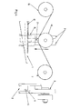
- Fig.1 shows the tensioner's diagram in respect of a drive belt in its initial position
- Figs. 2 and 3 show the tensioner's location in its subsequent positions that correspond to subsequent stages of its operation
- Fig. 4 shows a side diagram of the tensioner
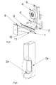
- Fig. 5 shows the tensioner and its particular components in a perspective view
- Fig. 6 shows the slide as a component of the tensioner in its perspective view.
- the automatic strand, belt, chain, etc. tensioner consists of the following components: slide 2 ( Fig. 6 ) shifting along the guideway 3, whose axis is supported with bearings and a tensioner pulley 4, and a key 1 which causes shifting and blocking of the slide 2.
- the guideway 3 with the slide 2 is fitted to the casing of the device in which the tensioner has been applied.
- At the lower part of the slide 2 there is a guideway 2a with a shifting key 1.
- the guideway 2a has an indent 2b, whose bearing surface is tilted towards the direction of the shift at ⁇ equalling the angle of the mutual tilt of the working surfaces 10 and 11 of the key 1.
- the angle between the working surfaces 10 and 11 of the key 1 ranges from 3 to 20 degrees, depending on the specific features and parameters of the device in which the tensioner has been applied.
- the key 1 has a protrusion 9 on its broader end. The protrusion 9 cooperates with the edge of the guideway 3, and restricts key shifting.
- the key 1 is placed in the guideway 2a, and the lower working surface of the key 11 touches the indent surface 2b, and its upper working surface 10 rests upon the lower surface of the guideway 3.
- the slide 2 is tightly fitted on the belt, which blocks it from upward shifting and prevents slacking.
- the force F which affects the key 1 causes the key's shifting along the direction of the force, which causes slide 2 downward shifting, and eliminates the slack.
- the tension of the rope on both pulleys 7 and 8 within the system is regulated steplessly, which prevents the slide's backward motion and reoccurrence of slack.
- the slide cannot move backward thanks to the system's self-locking features, and in certain applications thanks to the additional use of a ratchet toothed bar 5 which cooperates with the movable pawl 6.
- the slide shifts smoothly and in both directions, while in the solution presented in the invention concerned the shift occurs only in one direction.
Landscapes
- Engineering & Computer Science (AREA)
- General Engineering & Computer Science (AREA)
- Mechanical Engineering (AREA)
- Devices For Conveying Motion By Means Of Endless Flexible Members (AREA)
Abstract
Description
- The object of the invention pertains to an automatic strand, belt, chain, etc. tensioner.
- The automatic tensioner has been designed for application in all types of rope chain drives with belts, etc. which need constant strand or belt tension, as well as for other applications that require maintained constant belt tension.
- The Japanese patent application no.
JP002003294095 A1 - The Canadian patent application no.
CA000002246187 A1 - Strand drives with ropes or belts tend to have increased dive slack after some time of use, which is due to wear or extension of drive components. Therefore, there is a need to automatically compensate for the resulting differences in length.
- The objective of the invention has been to develop a tensioner that would eliminate the defects of the tensioners that have been known so far.
- The said objective has been meet in the form of the automatic tensioner being the subject of the invention concerned whose slide together with the tensioning pulley is fitted and can move along the guideway. It has a perpendicular guideway which collaborates with the key which is subject to the constant force exerted for instance by a spring.
- The angle between the working surfaces of the tensioner key ranges conveniently from 3 to 20 degrees.
- They key has a convenient feature, as its wider end has a protruding part or lip which cooperates with the guideway's edge and which restricts key shifting.
- The guideway has a convenient indent whose bearing surface is tilted towards the direction of the shift, and the tilt angle equals the angle of mutual tilt of both working surfaces of the key.
- The key's lateral surface has a convenient ratchet toothed bar which cooperates with the movable pawl on the guideway.
- The operation of the automatic tensioner being subject to the invention concerned is stepless, and its structure prevents any return shifting to the initial position, which in turn prevents tensioner backward motion, drive slacking, etc.
- Where the key's working surfaces have larger tilt angles or where there are stronger impact forces, the key can be equipped with an additional ratchet toothed bar.
- The invention has been explained on the drawing, where
Fig.1 shows the tensioner's diagram in respect of a drive belt in its initial position,Figs. 2 and 3 show the tensioner's location in its subsequent positions that correspond to subsequent stages of its operation,Fig. 4 shows a side diagram of the tensioner,Fig. 5 shows the tensioner and its particular components in a perspective view, andFig. 6 shows the slide as a component of the tensioner in its perspective view. - The automatic strand, belt, chain, etc. tensioner consists of the following components: slide 2 (
Fig. 6 ) shifting along theguideway 3, whose axis is supported with bearings and a tensioner pulley 4, and akey 1 which causes shifting and blocking of theslide 2. Theguideway 3 with theslide 2 is fitted to the casing of the device in which the tensioner has been applied. At the lower part of theslide 2 there is aguideway 2a with a shiftingkey 1. Theguideway 2a has anindent 2b, whose bearing surface is tilted towards the direction of the shift at α equalling the angle of the mutual tilt of theworking surfaces key 1. The angle between theworking surfaces key 1 ranges from 3 to 20 degrees, depending on the specific features and parameters of the device in which the tensioner has been applied. Thekey 1 has a protrusion 9 on its broader end. The protrusion 9 cooperates with the edge of theguideway 3, and restricts key shifting. - It the initial position of the tensioner, the
key 1 is placed in theguideway 2a, and the lower working surface of thekey 11 touches theindent surface 2b, and its upper workingsurface 10 rests upon the lower surface of theguideway 3. In this way, theslide 2 is tightly fitted on the belt, which blocks it from upward shifting and prevents slacking. Should slacking occur (Figs. 1, 2 and 3 ) in the drive system, the force F which affects thekey 1 causes the key's shifting along the direction of the force, which causesslide 2 downward shifting, and eliminates the slack. Thanks to such a structure, the tension of the rope on bothpulleys 7 and 8 within the system is regulated steplessly, which prevents the slide's backward motion and reoccurrence of slack. The slide cannot move backward thanks to the system's self-locking features, and in certain applications thanks to the additional use of aratchet toothed bar 5 which cooperates with themovable pawl 6. As regards the existing solutions which have no self-locking components, the slide shifts smoothly and in both directions, while in the solution presented in the invention concerned the shift occurs only in one direction.
Claims (5)
- An automatic strand, belt or chain tensioner that shifts between the drive powering pulley and the pulley being powered, characterized in that it involves a slide (2) with a tensioning pulley (4) of the tensioner which shifts along the guideway (3) and has a perpendicular guideway (2a) which cooperates with the key (1) that is subject to a constant force (F) exerted for instance by a spring.
- The tensioner according to claim 1, characterized in that the angle between the working surfaces (10) and (11) of the key (1) ranging from 3 to 20 degrees.
- The tensioner according to claim 1, characterized in that it involves the key (1) which has a protrusion (9) on its wider end, which protrusion (9) cooperates with the edge of the guideway (3) and restricts key shifting.
- The tensioner according to claim 1, characterized in that it involves a guideway (2a), which has an indent (2b) whose bearing surface is tilted towards the direction of the shift at (α) equalling the angle of the mutual tilt of the working surfaces (10) and (11) of the key.
- The tensioner according to claim 1, characterized in that it involves the key's (1) lateral surface with a ratchet toothed bar (5) which cooperates with the movable pawl (6) on the guideway (3).
Applications Claiming Priority (1)
| Application Number | Priority Date | Filing Date | Title |
|---|---|---|---|
| PL408597A PL223981B1 (en) | 2014-06-17 | 2014-06-17 | Automatic tightener |
Publications (2)
| Publication Number | Publication Date |
|---|---|
| EP2990688A1 true EP2990688A1 (en) | 2016-03-02 |
| EP2990688B1 EP2990688B1 (en) | 2021-02-17 |
Family
ID=53673881
Family Applications (1)
| Application Number | Title | Priority Date | Filing Date |
|---|---|---|---|
| EP15460026.6A Not-in-force EP2990688B1 (en) | 2014-06-17 | 2015-06-17 | Automatic tensioner |
Country Status (2)
| Country | Link |
|---|---|
| EP (1) | EP2990688B1 (en) |
| PL (1) | PL223981B1 (en) |
Cited By (1)
| Publication number | Priority date | Publication date | Assignee | Title |
|---|---|---|---|---|
| CN106402295A (en) * | 2016-08-24 | 2017-02-15 | 咸阳蓝博机械有限公司 | Outer linear moving die set |
Families Citing this family (1)
| Publication number | Priority date | Publication date | Assignee | Title |
|---|---|---|---|---|
| DE102024135026A1 (en) | 2024-11-27 | 2026-05-28 | Krones Aktiengesellschaft | Conveyor device and method for conveying unit loads on a support |
Citations (5)
| Publication number | Priority date | Publication date | Assignee | Title |
|---|---|---|---|---|
| US2469296A (en) * | 1944-03-24 | 1949-05-03 | Sydney T Farrell | Belt driving mechanism |
| FR1166119A (en) * | 1956-12-04 | 1958-11-03 | Sedis Transmissions Mec | Automatic chain tensioner |
| US3978737A (en) * | 1975-08-27 | 1976-09-07 | Xerox Corporation | Chain tensioning device |
| CA2246187A1 (en) | 1997-09-01 | 2000-03-01 | Ontario Drive & Gear Limited | Automatic chain tensioner |
| JP2003294095A (en) | 2002-04-04 | 2003-10-15 | Kawasaki Heavy Ind Ltd | Ratchet type automatic tensioner |
-
2014
- 2014-06-17 PL PL408597A patent/PL223981B1/en unknown
-
2015
- 2015-06-17 EP EP15460026.6A patent/EP2990688B1/en not_active Not-in-force
Patent Citations (5)
| Publication number | Priority date | Publication date | Assignee | Title |
|---|---|---|---|---|
| US2469296A (en) * | 1944-03-24 | 1949-05-03 | Sydney T Farrell | Belt driving mechanism |
| FR1166119A (en) * | 1956-12-04 | 1958-11-03 | Sedis Transmissions Mec | Automatic chain tensioner |
| US3978737A (en) * | 1975-08-27 | 1976-09-07 | Xerox Corporation | Chain tensioning device |
| CA2246187A1 (en) | 1997-09-01 | 2000-03-01 | Ontario Drive & Gear Limited | Automatic chain tensioner |
| JP2003294095A (en) | 2002-04-04 | 2003-10-15 | Kawasaki Heavy Ind Ltd | Ratchet type automatic tensioner |
Cited By (1)
| Publication number | Priority date | Publication date | Assignee | Title |
|---|---|---|---|---|
| CN106402295A (en) * | 2016-08-24 | 2017-02-15 | 咸阳蓝博机械有限公司 | Outer linear moving die set |
Also Published As
| Publication number | Publication date |
|---|---|
| PL408597A1 (en) | 2015-12-21 |
| EP2990688B1 (en) | 2021-02-17 |
| PL223981B1 (en) | 2016-11-30 |
Similar Documents
| Publication | Publication Date | Title |
|---|---|---|
| ES2532471T3 (en) | Direct drive and low friction conveyor belt | |
| WO2015196268A8 (en) | Orbital tensioner assembly | |
| EP2532922A3 (en) | Tensioning system and method of tensioning a belt or chain | |
| EP1881230A3 (en) | Low friction chain | |
| UA98607C2 (en) | Drive system with step chain or pallet chain for transportation device and transportation device with corresponding drive system | |
| EP2990688B1 (en) | Automatic tensioner | |
| EP1724217A3 (en) | Drive for a conveyor belt comprising a transport chain | |
| RU2012140464A (en) | UNLOADING DEVICE | |
| EP1591381A3 (en) | Belt junction conveyor | |
| EP1992578A3 (en) | Driven track system | |
| US6269942B1 (en) | Force transmission or transport device | |
| KR20180015573A (en) | Chain drive system | |
| PL365584A1 (en) | Drive ring cvt belt | |
| CN111634624A (en) | An automatic tensioning conveying device | |
| KR101445136B1 (en) | Chain roller reverse rotation working device for conveyor system | |
| JP6265810B2 (en) | Chain guide and chain transmission | |
| CN212711223U (en) | Automatic conveyor of tensioning | |
| CN112539257A (en) | Tensioning structure of transmission line | |
| US389835A (en) | Oeville cooley | |
| RU51149U1 (en) | FLEXIBLE TIGHTENER | |
| WO2017109969A1 (en) | Shutter opening/closing device | |
| RU155672U1 (en) | GEARBOX WITH REVERSE DEVICE | |
| CN104819256B (en) | Tensioning device for a traction mechanism drive | |
| KR101159258B1 (en) | Regulating device of tension | |
| JP2020535082A (en) | Tension regulator for chain drive jaw system |
Legal Events
| Date | Code | Title | Description |
|---|---|---|---|
| PUAI | Public reference made under article 153(3) epc to a published international application that has entered the european phase |
Free format text: ORIGINAL CODE: 0009012 |
|
| AK | Designated contracting states |
Kind code of ref document: A1 Designated state(s): AL AT BE BG CH CY CZ DE DK EE ES FI FR GB GR HR HU IE IS IT LI LT LU LV MC MK MT NL NO PL PT RO RS SE SI SK SM TR |
|
| AX | Request for extension of the european patent |
Extension state: BA ME |
|
| 17P | Request for examination filed |
Effective date: 20160427 |
|
| RBV | Designated contracting states (corrected) |
Designated state(s): AL AT BE BG CH CY CZ DE DK EE ES FI FR GB GR HR HU IE IS IT LI LT LU LV MC MK MT NL NO PL PT RO RS SE SI SK SM TR |
|
| GRAP | Despatch of communication of intention to grant a patent |
Free format text: ORIGINAL CODE: EPIDOSNIGR1 |
|
| STAA | Information on the status of an ep patent application or granted ep patent |
Free format text: STATUS: GRANT OF PATENT IS INTENDED |
|
| INTG | Intention to grant announced |
Effective date: 20191217 |
|
| GRAS | Grant fee paid |
Free format text: ORIGINAL CODE: EPIDOSNIGR3 |
|
| GRAA | (expected) grant |
Free format text: ORIGINAL CODE: 0009210 |
|
| STAA | Information on the status of an ep patent application or granted ep patent |
Free format text: STATUS: THE PATENT HAS BEEN GRANTED |
|
| AK | Designated contracting states |
Kind code of ref document: B1 Designated state(s): AL AT BE BG CH CY CZ DE DK EE ES FI FR GB GR HR HU IE IS IT LI LT LU LV MC MK MT NL NO PL PT RO RS SE SI SK SM TR |
|
| REG | Reference to a national code |
Ref country code: GB Ref legal event code: FG4D |
|
| REG | Reference to a national code |
Ref country code: CH Ref legal event code: EP |
|
| REG | Reference to a national code |
Ref country code: DE Ref legal event code: R096 Ref document number: 602015065540 Country of ref document: DE |
|
| REG | Reference to a national code |
Ref country code: AT Ref legal event code: REF Ref document number: 1361888 Country of ref document: AT Kind code of ref document: T Effective date: 20210315 |
|
| REG | Reference to a national code |
Ref country code: IE Ref legal event code: FG4D |
|
| REG | Reference to a national code |
Ref country code: LT Ref legal event code: MG9D |
|
| REG | Reference to a national code |
Ref country code: NL Ref legal event code: MP Effective date: 20210217 |
|
| PG25 | Lapsed in a contracting state [announced via postgrant information from national office to epo] |
Ref country code: PT Free format text: LAPSE BECAUSE OF FAILURE TO SUBMIT A TRANSLATION OF THE DESCRIPTION OR TO PAY THE FEE WITHIN THE PRESCRIBED TIME-LIMIT Effective date: 20210617 Ref country code: LT Free format text: LAPSE BECAUSE OF FAILURE TO SUBMIT A TRANSLATION OF THE DESCRIPTION OR TO PAY THE FEE WITHIN THE PRESCRIBED TIME-LIMIT Effective date: 20210217 Ref country code: NO Free format text: LAPSE BECAUSE OF FAILURE TO SUBMIT A TRANSLATION OF THE DESCRIPTION OR TO PAY THE FEE WITHIN THE PRESCRIBED TIME-LIMIT Effective date: 20210517 Ref country code: BG Free format text: LAPSE BECAUSE OF FAILURE TO SUBMIT A TRANSLATION OF THE DESCRIPTION OR TO PAY THE FEE WITHIN THE PRESCRIBED TIME-LIMIT Effective date: 20210517 Ref country code: HR Free format text: LAPSE BECAUSE OF FAILURE TO SUBMIT A TRANSLATION OF THE DESCRIPTION OR TO PAY THE FEE WITHIN THE PRESCRIBED TIME-LIMIT Effective date: 20210217 Ref country code: GR Free format text: LAPSE BECAUSE OF FAILURE TO SUBMIT A TRANSLATION OF THE DESCRIPTION OR TO PAY THE FEE WITHIN THE PRESCRIBED TIME-LIMIT Effective date: 20210518 Ref country code: FI Free format text: LAPSE BECAUSE OF FAILURE TO SUBMIT A TRANSLATION OF THE DESCRIPTION OR TO PAY THE FEE WITHIN THE PRESCRIBED TIME-LIMIT Effective date: 20210217 |
|
| REG | Reference to a national code |
Ref country code: AT Ref legal event code: MK05 Ref document number: 1361888 Country of ref document: AT Kind code of ref document: T Effective date: 20210217 |
|
| PG25 | Lapsed in a contracting state [announced via postgrant information from national office to epo] |
Ref country code: LV Free format text: LAPSE BECAUSE OF FAILURE TO SUBMIT A TRANSLATION OF THE DESCRIPTION OR TO PAY THE FEE WITHIN THE PRESCRIBED TIME-LIMIT Effective date: 20210217 Ref country code: RS Free format text: LAPSE BECAUSE OF FAILURE TO SUBMIT A TRANSLATION OF THE DESCRIPTION OR TO PAY THE FEE WITHIN THE PRESCRIBED TIME-LIMIT Effective date: 20210217 Ref country code: NL Free format text: LAPSE BECAUSE OF FAILURE TO SUBMIT A TRANSLATION OF THE DESCRIPTION OR TO PAY THE FEE WITHIN THE PRESCRIBED TIME-LIMIT Effective date: 20210217 Ref country code: PL Free format text: LAPSE BECAUSE OF FAILURE TO SUBMIT A TRANSLATION OF THE DESCRIPTION OR TO PAY THE FEE WITHIN THE PRESCRIBED TIME-LIMIT Effective date: 20210217 Ref country code: SE Free format text: LAPSE BECAUSE OF FAILURE TO SUBMIT A TRANSLATION OF THE DESCRIPTION OR TO PAY THE FEE WITHIN THE PRESCRIBED TIME-LIMIT Effective date: 20210217 |
|
| PG25 | Lapsed in a contracting state [announced via postgrant information from national office to epo] |
Ref country code: IS Free format text: LAPSE BECAUSE OF FAILURE TO SUBMIT A TRANSLATION OF THE DESCRIPTION OR TO PAY THE FEE WITHIN THE PRESCRIBED TIME-LIMIT Effective date: 20210617 |
|
| PG25 | Lapsed in a contracting state [announced via postgrant information from national office to epo] |
Ref country code: AT Free format text: LAPSE BECAUSE OF FAILURE TO SUBMIT A TRANSLATION OF THE DESCRIPTION OR TO PAY THE FEE WITHIN THE PRESCRIBED TIME-LIMIT Effective date: 20210217 Ref country code: SM Free format text: LAPSE BECAUSE OF FAILURE TO SUBMIT A TRANSLATION OF THE DESCRIPTION OR TO PAY THE FEE WITHIN THE PRESCRIBED TIME-LIMIT Effective date: 20210217 Ref country code: EE Free format text: LAPSE BECAUSE OF FAILURE TO SUBMIT A TRANSLATION OF THE DESCRIPTION OR TO PAY THE FEE WITHIN THE PRESCRIBED TIME-LIMIT Effective date: 20210217 Ref country code: CZ Free format text: LAPSE BECAUSE OF FAILURE TO SUBMIT A TRANSLATION OF THE DESCRIPTION OR TO PAY THE FEE WITHIN THE PRESCRIBED TIME-LIMIT Effective date: 20210217 |
|
| REG | Reference to a national code |
Ref country code: DE Ref legal event code: R097 Ref document number: 602015065540 Country of ref document: DE |
|
| PG25 | Lapsed in a contracting state [announced via postgrant information from national office to epo] |
Ref country code: RO Free format text: LAPSE BECAUSE OF FAILURE TO SUBMIT A TRANSLATION OF THE DESCRIPTION OR TO PAY THE FEE WITHIN THE PRESCRIBED TIME-LIMIT Effective date: 20210217 Ref country code: SK Free format text: LAPSE BECAUSE OF FAILURE TO SUBMIT A TRANSLATION OF THE DESCRIPTION OR TO PAY THE FEE WITHIN THE PRESCRIBED TIME-LIMIT Effective date: 20210217 Ref country code: DK Free format text: LAPSE BECAUSE OF FAILURE TO SUBMIT A TRANSLATION OF THE DESCRIPTION OR TO PAY THE FEE WITHIN THE PRESCRIBED TIME-LIMIT Effective date: 20210217 Ref country code: ES Free format text: LAPSE BECAUSE OF FAILURE TO SUBMIT A TRANSLATION OF THE DESCRIPTION OR TO PAY THE FEE WITHIN THE PRESCRIBED TIME-LIMIT Effective date: 20210217 |
|
| PLBE | No opposition filed within time limit |
Free format text: ORIGINAL CODE: 0009261 |
|
| STAA | Information on the status of an ep patent application or granted ep patent |
Free format text: STATUS: NO OPPOSITION FILED WITHIN TIME LIMIT |
|
| REG | Reference to a national code |
Ref country code: DE Ref legal event code: R119 Ref document number: 602015065540 Country of ref document: DE |
|
| 26N | No opposition filed |
Effective date: 20211118 |
|
| PG25 | Lapsed in a contracting state [announced via postgrant information from national office to epo] |
Ref country code: AL Free format text: LAPSE BECAUSE OF FAILURE TO SUBMIT A TRANSLATION OF THE DESCRIPTION OR TO PAY THE FEE WITHIN THE PRESCRIBED TIME-LIMIT Effective date: 20210217 Ref country code: MC Free format text: LAPSE BECAUSE OF FAILURE TO SUBMIT A TRANSLATION OF THE DESCRIPTION OR TO PAY THE FEE WITHIN THE PRESCRIBED TIME-LIMIT Effective date: 20210217 |
|
| REG | Reference to a national code |
Ref country code: CH Ref legal event code: PL |
|
| GBPC | Gb: european patent ceased through non-payment of renewal fee |
Effective date: 20210617 |
|
| PG25 | Lapsed in a contracting state [announced via postgrant information from national office to epo] |
Ref country code: SI Free format text: LAPSE BECAUSE OF FAILURE TO SUBMIT A TRANSLATION OF THE DESCRIPTION OR TO PAY THE FEE WITHIN THE PRESCRIBED TIME-LIMIT Effective date: 20210217 |
|
| REG | Reference to a national code |
Ref country code: BE Ref legal event code: MM Effective date: 20210630 |
|
| PG25 | Lapsed in a contracting state [announced via postgrant information from national office to epo] |
Ref country code: LU Free format text: LAPSE BECAUSE OF NON-PAYMENT OF DUE FEES Effective date: 20210617 |
|
| PG25 | Lapsed in a contracting state [announced via postgrant information from national office to epo] |
Ref country code: LI Free format text: LAPSE BECAUSE OF NON-PAYMENT OF DUE FEES Effective date: 20210630 Ref country code: IT Free format text: LAPSE BECAUSE OF FAILURE TO SUBMIT A TRANSLATION OF THE DESCRIPTION OR TO PAY THE FEE WITHIN THE PRESCRIBED TIME-LIMIT Effective date: 20210217 Ref country code: IE Free format text: LAPSE BECAUSE OF NON-PAYMENT OF DUE FEES Effective date: 20210617 Ref country code: GB Free format text: LAPSE BECAUSE OF NON-PAYMENT OF DUE FEES Effective date: 20210617 Ref country code: DE Free format text: LAPSE BECAUSE OF NON-PAYMENT OF DUE FEES Effective date: 20220101 Ref country code: CH Free format text: LAPSE BECAUSE OF NON-PAYMENT OF DUE FEES Effective date: 20210630 |
|
| PG25 | Lapsed in a contracting state [announced via postgrant information from national office to epo] |
Ref country code: IS Free format text: LAPSE BECAUSE OF FAILURE TO SUBMIT A TRANSLATION OF THE DESCRIPTION OR TO PAY THE FEE WITHIN THE PRESCRIBED TIME-LIMIT Effective date: 20210617 Ref country code: FR Free format text: LAPSE BECAUSE OF NON-PAYMENT OF DUE FEES Effective date: 20210630 |
|
| PG25 | Lapsed in a contracting state [announced via postgrant information from national office to epo] |
Ref country code: BE Free format text: LAPSE BECAUSE OF NON-PAYMENT OF DUE FEES Effective date: 20210630 |
|
| PG25 | Lapsed in a contracting state [announced via postgrant information from national office to epo] |
Ref country code: HU Free format text: LAPSE BECAUSE OF FAILURE TO SUBMIT A TRANSLATION OF THE DESCRIPTION OR TO PAY THE FEE WITHIN THE PRESCRIBED TIME-LIMIT; INVALID AB INITIO Effective date: 20150617 |
|
| PG25 | Lapsed in a contracting state [announced via postgrant information from national office to epo] |
Ref country code: CY Free format text: LAPSE BECAUSE OF FAILURE TO SUBMIT A TRANSLATION OF THE DESCRIPTION OR TO PAY THE FEE WITHIN THE PRESCRIBED TIME-LIMIT Effective date: 20210217 |
|
| PG25 | Lapsed in a contracting state [announced via postgrant information from national office to epo] |
Ref country code: MK Free format text: LAPSE BECAUSE OF FAILURE TO SUBMIT A TRANSLATION OF THE DESCRIPTION OR TO PAY THE FEE WITHIN THE PRESCRIBED TIME-LIMIT Effective date: 20210217 |
|
| PG25 | Lapsed in a contracting state [announced via postgrant information from national office to epo] |
Ref country code: TR Free format text: LAPSE BECAUSE OF FAILURE TO SUBMIT A TRANSLATION OF THE DESCRIPTION OR TO PAY THE FEE WITHIN THE PRESCRIBED TIME-LIMIT Effective date: 20210217 |
|
| PG25 | Lapsed in a contracting state [announced via postgrant information from national office to epo] |
Ref country code: MT Free format text: LAPSE BECAUSE OF FAILURE TO SUBMIT A TRANSLATION OF THE DESCRIPTION OR TO PAY THE FEE WITHIN THE PRESCRIBED TIME-LIMIT Effective date: 20210217 |