EP2990674A1 - Sealing assembly, in particular for spherical roller bearings - Google Patents
Sealing assembly, in particular for spherical roller bearings Download PDFInfo
- Publication number
- EP2990674A1 EP2990674A1 EP15178948.4A EP15178948A EP2990674A1 EP 2990674 A1 EP2990674 A1 EP 2990674A1 EP 15178948 A EP15178948 A EP 15178948A EP 2990674 A1 EP2990674 A1 EP 2990674A1
- Authority
- EP
- European Patent Office
- Prior art keywords
- annular
- lip
- metal insert
- coupling portion
- sealing assembly
- Prior art date
- Legal status (The legal status is an assumption and is not a legal conclusion. Google has not performed a legal analysis and makes no representation as to the accuracy of the status listed.)
- Granted
Links
Images


Classifications
-
- F—MECHANICAL ENGINEERING; LIGHTING; HEATING; WEAPONS; BLASTING
- F16—ENGINEERING ELEMENTS AND UNITS; GENERAL MEASURES FOR PRODUCING AND MAINTAINING EFFECTIVE FUNCTIONING OF MACHINES OR INSTALLATIONS; THERMAL INSULATION IN GENERAL
- F16C—SHAFTS; FLEXIBLE SHAFTS; ELEMENTS OR CRANKSHAFT MECHANISMS; ROTARY BODIES OTHER THAN GEARING ELEMENTS; BEARINGS
- F16C33/00—Parts of bearings; Special methods for making bearings or parts thereof
- F16C33/72—Sealings
- F16C33/76—Sealings of ball or roller bearings
- F16C33/78—Sealings of ball or roller bearings with a diaphragm, disc, or ring, with or without resilient members
- F16C33/7803—Sealings of ball or roller bearings with a diaphragm, disc, or ring, with or without resilient members suited for particular types of rolling bearings
- F16C33/7806—Sealings of ball or roller bearings with a diaphragm, disc, or ring, with or without resilient members suited for particular types of rolling bearings for spherical roller bearings
-
- F—MECHANICAL ENGINEERING; LIGHTING; HEATING; WEAPONS; BLASTING
- F16—ENGINEERING ELEMENTS AND UNITS; GENERAL MEASURES FOR PRODUCING AND MAINTAINING EFFECTIVE FUNCTIONING OF MACHINES OR INSTALLATIONS; THERMAL INSULATION IN GENERAL
- F16C—SHAFTS; FLEXIBLE SHAFTS; ELEMENTS OR CRANKSHAFT MECHANISMS; ROTARY BODIES OTHER THAN GEARING ELEMENTS; BEARINGS
- F16C33/00—Parts of bearings; Special methods for making bearings or parts thereof
- F16C33/72—Sealings
- F16C33/76—Sealings of ball or roller bearings
- F16C33/768—Sealings of ball or roller bearings between relatively stationary parts, i.e. static seals
-
- F—MECHANICAL ENGINEERING; LIGHTING; HEATING; WEAPONS; BLASTING
- F16—ENGINEERING ELEMENTS AND UNITS; GENERAL MEASURES FOR PRODUCING AND MAINTAINING EFFECTIVE FUNCTIONING OF MACHINES OR INSTALLATIONS; THERMAL INSULATION IN GENERAL
- F16C—SHAFTS; FLEXIBLE SHAFTS; ELEMENTS OR CRANKSHAFT MECHANISMS; ROTARY BODIES OTHER THAN GEARING ELEMENTS; BEARINGS
- F16C33/00—Parts of bearings; Special methods for making bearings or parts thereof
- F16C33/72—Sealings
- F16C33/76—Sealings of ball or roller bearings
- F16C33/78—Sealings of ball or roller bearings with a diaphragm, disc, or ring, with or without resilient members
- F16C33/7816—Details of the sealing or parts thereof, e.g. geometry, material
- F16C33/783—Details of the sealing or parts thereof, e.g. geometry, material of the mounting region
-
- F—MECHANICAL ENGINEERING; LIGHTING; HEATING; WEAPONS; BLASTING
- F16—ENGINEERING ELEMENTS AND UNITS; GENERAL MEASURES FOR PRODUCING AND MAINTAINING EFFECTIVE FUNCTIONING OF MACHINES OR INSTALLATIONS; THERMAL INSULATION IN GENERAL
- F16C—SHAFTS; FLEXIBLE SHAFTS; ELEMENTS OR CRANKSHAFT MECHANISMS; ROTARY BODIES OTHER THAN GEARING ELEMENTS; BEARINGS
- F16C33/00—Parts of bearings; Special methods for making bearings or parts thereof
- F16C33/72—Sealings
- F16C33/76—Sealings of ball or roller bearings
- F16C33/78—Sealings of ball or roller bearings with a diaphragm, disc, or ring, with or without resilient members
- F16C33/784—Sealings of ball or roller bearings with a diaphragm, disc, or ring, with or without resilient members mounted to a groove in the inner surface of the outer race and extending toward the inner race
- F16C33/7843—Sealings of ball or roller bearings with a diaphragm, disc, or ring, with or without resilient members mounted to a groove in the inner surface of the outer race and extending toward the inner race with a single annular sealing disc
- F16C33/7853—Sealings of ball or roller bearings with a diaphragm, disc, or ring, with or without resilient members mounted to a groove in the inner surface of the outer race and extending toward the inner race with a single annular sealing disc with one or more sealing lips to contact the inner race
- F16C33/7856—Sealings of ball or roller bearings with a diaphragm, disc, or ring, with or without resilient members mounted to a groove in the inner surface of the outer race and extending toward the inner race with a single annular sealing disc with one or more sealing lips to contact the inner race with a single sealing lip
-
- F—MECHANICAL ENGINEERING; LIGHTING; HEATING; WEAPONS; BLASTING
- F16—ENGINEERING ELEMENTS AND UNITS; GENERAL MEASURES FOR PRODUCING AND MAINTAINING EFFECTIVE FUNCTIONING OF MACHINES OR INSTALLATIONS; THERMAL INSULATION IN GENERAL
- F16C—SHAFTS; FLEXIBLE SHAFTS; ELEMENTS OR CRANKSHAFT MECHANISMS; ROTARY BODIES OTHER THAN GEARING ELEMENTS; BEARINGS
- F16C23/00—Bearings for exclusively rotary movement adjustable for aligning or positioning
- F16C23/06—Ball or roller bearings
- F16C23/08—Ball or roller bearings self-adjusting
- F16C23/082—Ball or roller bearings self-adjusting by means of at least one substantially spherical surface
- F16C23/086—Ball or roller bearings self-adjusting by means of at least one substantially spherical surface forming a track for rolling elements
-
- F—MECHANICAL ENGINEERING; LIGHTING; HEATING; WEAPONS; BLASTING
- F16—ENGINEERING ELEMENTS AND UNITS; GENERAL MEASURES FOR PRODUCING AND MAINTAINING EFFECTIVE FUNCTIONING OF MACHINES OR INSTALLATIONS; THERMAL INSULATION IN GENERAL
- F16C—SHAFTS; FLEXIBLE SHAFTS; ELEMENTS OR CRANKSHAFT MECHANISMS; ROTARY BODIES OTHER THAN GEARING ELEMENTS; BEARINGS
- F16C33/00—Parts of bearings; Special methods for making bearings or parts thereof
- F16C33/30—Parts of ball or roller bearings
- F16C33/58—Raceways; Race rings
- F16C33/583—Details of specific parts of races
-
- F—MECHANICAL ENGINEERING; LIGHTING; HEATING; WEAPONS; BLASTING
- F16—ENGINEERING ELEMENTS AND UNITS; GENERAL MEASURES FOR PRODUCING AND MAINTAINING EFFECTIVE FUNCTIONING OF MACHINES OR INSTALLATIONS; THERMAL INSULATION IN GENERAL
- F16C—SHAFTS; FLEXIBLE SHAFTS; ELEMENTS OR CRANKSHAFT MECHANISMS; ROTARY BODIES OTHER THAN GEARING ELEMENTS; BEARINGS
- F16C33/00—Parts of bearings; Special methods for making bearings or parts thereof
- F16C33/72—Sealings
- F16C33/76—Sealings of ball or roller bearings
- F16C33/78—Sealings of ball or roller bearings with a diaphragm, disc, or ring, with or without resilient members
- F16C33/7816—Details of the sealing or parts thereof, e.g. geometry, material
- F16C33/782—Details of the sealing or parts thereof, e.g. geometry, material of the sealing region
Definitions
- the present invention relates to a sealing assembly, particularly adapted to equip spherical roller bearings, of the type known with the acronym SRB.
- the invention further relates to a rolling bearing provided with such a sealing assembly.
- the sealing assemblies intended to equip rolling bearings of the SRB type must satisfy various needs. Firstly, they must be able to allow relative offsettings between the outer ring and the inner ring of the bearing without the sealing action coming less as a consequence. Furthermore, they must have low friction independently of possible relative offsettings or changes of center distance between the two annular elements, i.e. of the outer ring and the inner ring of a bearing, respectively. Finally, they must be easy to assemble without risk of damage.
- all these features are desirable also for sealing assemblies not specifically intended for SRB type bearings, in particular when the two mechanical members between which the sealing assembly is interposed are subject to issues similar to those found on SRB type bearings. EP0708263A1 does not solve these problems.
- the particular conformation of the coupling portion of the sealing assembly, in particular at the outer ring of the rolling bearing, and of the C-shaped dynamic sealing lip, in particular intended to couple with an oblique sealing surface of the inner ring of the roller bearing allow to keep the sealing assembly always in the correct position in its static sealing seat leaving the dynamic sealing lip free to be deformed following the possible offsettings between the inner and outer rings which could occur in use, substantially without increasing the inference of the sealing lip and consequently keeping frictions low.
- the conformation of the coupling portion allows to insert the sealing assembly easily and rapidly in position using a simple tool, without risking any damage to the sealing assembly or to the housing seat thereof.
- reference numeral 1 indicates as a whole a low friction sealing assembly, in particular designed to be mounted on and become an integral part of a rolling bearing 2, especially but not exclusively of the so-called SRB (Spherical Roller Bearing) type.
- SRB Spherical Roller Bearing
- the sealing assembly 1 can be inserted in use between the outer ring 3 and the inner ring 4 of the rolling bearing 2 to protect the rolling bodies, known and not shown for the sake of simplicity, from external contaminants (in SRB bearings constituted by two crowns of rollers) interposed between the outer ring 3 and the inner ring 4 to make them relatively rotational with low friction, as well as to retain possible lubricant between the rings 3 and 4.
- the rings 3 and 4 and the sealing assembly 1 are symmetric with respect to a symmetry axis A, which is in common to the bearing 2 and the sealing assembly 1, when the rings 3 and 4 are arranged coaxially.
- the sealing assembly 1 can be inserted between any two mechanical members or elements 3 and 4 to protect an annular gap 5 enclosed between the elements 3 and 4 and, in the case of a rolling bearing, normally occupied by the rolling bodies and by the respective rolling tracks (also known and not shown for the sake of simplicity).
- the sealing assembly 1 comprises an annular metal insert 6 and an annular seal 7 made of elastomeric material which has been constrained integrally in one piece to the metal insert 6, for instance and preferably by bonding during the step of vulcanizing, according to a compression co-molding process of the seal 7 onto the metal insert 6, known in the art and which therefore is not described in detail for the sake of simplicity.
- the annular seal 7 comprises at least one elastically deformable first annular lip 8, which radially extends in cantilever manner from a first annular edge 9 of the metal insert 6 and an annular coupling portion 10 arranged on a second annular edge 11 of the metal insert 6, opposite to the first annular edge 9.
- the lip 8, which is intended in use to perform a dynamic sealing action on one of the members 3 and 4 in relative rotation, in the case in point on the inner ring 4, is formed entirely in elastomeric material and, according to a first aspect of the invention, is substantially C-shaped in radial section having a concavity 12 facing the same side of the first face 13 of the metallic insert 6.
- the annular lip 8 is completely free of support by the metal insert 6, so as to be able to bend elastically in use both in radial and axial direction, folding towards its concavity 12 and ends with a free end 14 which, in the illustrated example, faces towards the symmetry axis A and is intended to cooperate in sliding manner with the inner ring 4.
- the coupling portion 10 is intended to allow the angular coupling of the sealing assembly 1 with the other element in relative rotation, in the case in point with the outer ring 3, and to perform a static sealing action thereon.
- the coupling portion 10, according to a known arrangement, is provided with at least one elastically deformable second lip belonging to the seal 7.
- the coupling portion 10 is provided, in combination, with three elastically deformable annular lips 15, 16 and 17, which extend in cantilever manner from the coupling portion 10 on the side opposite to the metal insert 6; in particular, a second lip 15 and a third lip 16 of the seal 7 extend in cantilever manner from the coupling portion 10 in opposite directions, the lip 15 on the side of the first face 13 of the metal insert 6 and the lip 16 on the side of the second face 18, opposite to the first face 13, of the metal insert 6; the lips 15 and 16, according to the invention, are adapted to assume a deformed configuration in use ( figure 1 ), in which they are aligned substantially along an oblique straight line R1 with respect to the symmetry axis A of the sealing assembly 1.
- the metal insert 6 is incorporated at least in part in the annular seal 7, which covers the first face 13 and also covers, passing over them, both the first and the second annular edge 9 and 11.
- the second annular edge 11 of the metal insert 6 is circumferentially provided ( figures 4 and 7 ) with a plurality of indentations 19, each having a radial depth substantially equal to the radial extension of the coupling portion 10 ( figure 3 ), so that the second annular edge 11 extends alternatively in the coupling portion 10 with its first circumferential stretches 20, and substantially outside the coupling portion 10 with its second circumferential stretches 21.
- the second annular edge 11 ends in radial direction by means of its circumferential stretches 21, substantially at a root portion 22 of the annular lip 16 ( figures 2 and 3 ).
- the coupling portion 10 is provided, in annular positions different from those occupied by the circumferential indentations 19 of the annular edge 11 and, thus only at selected stretches 20, with a first pair of radial slots 23 ( figure 6 ), aligned and diametrically opposite to each other, which interrupt the circumferential continuity of the coupling portion 10 for the entire radial extension thereof and which are obtained on the side of the annular lip 15, radially cutting also the annular lip 15 itself, and with a second pair of radial slots 23' ( figure 5 ), aligned and diametrically opposite to each other, which also interrupt the circumferential continuity of the coupling portion 10 for the entire radial extension thereof and are obtained on the side of the annular lips 16,17, radially cutting also the lips 16,17 themselves.
- the radial slots 23' are obtained in an offset and different position with respect to that occupied by the slots 23 and in particular and preferably arranged at a right angle with respect to the angular position of the radial slots 23.
- These radial slots 23 and 23' angularly offset with respect to one another allow to release possible overpressure (e.g. caused by the heating of the lubricant grease with a consequent evaporation of part of its components) outside the bearing 2, in particular outside the annular gap 5, without causing the movement of the seal 1 and without the static action exerted by the coupling portion 10 in use coming less.
- the lips 15,16 are shaped so as to each have a respective rotation center C for a sealing free end 24 thereof of lip 15 and a sealing free end 25 of lip 16; the rotation centers C of the lips 15 and 16 are arranged on the oblique straight line R1 converging towards the symmetry axis A of the sealing assembly 1.
- the first annular edge of the metal insert 6 is a radially inner edge 9 thereof and the second annular edge is a radially outer edge 11 thereof; in this case, the oblique straight line R1 along which the lips 15,16 and the respective rotation centers C are substantially aligned converges towards the symmetry axis A on the side opposite to face 13 of the metal insert 6, i.e. converges towards axis A on the side of the opposite face 18.
- the lips 16 and 17 have respective sealing free ends 25 for the lip 16, and 26 for the lip 17, both facing towards the side of the second face 18 of the annular insert 6, arranged substantially flush with an extradox portion 27 ( figure 2 ) of the C-shaped lip 8, portion 27 opposite to the concavity 12; furthermore, the lip 17 is substantially oriented obliquely and has the sealing free end 26 thereof facing towards the symmetry axis A on the side of the face 18.
- the lip 16 and the lip 17, in undeformed conditions such as those illustrated in figures from 2,3 and 5,6, are substantially parallel to one another and the lip 17 is carried by the radially outermost coupling portion 10 with respect to the lip 16.
- the lip 15 is carried by the coupling portion 10 to a radial position such as to be arranged substantially radially between the lips 16 and 17, but on the side opposite to the lips 16,17 with respect to the metal insert 6.
- the coupling portion 10 has an annular axial shoulder 28 on the side of the lip 15 arranged radially on the outside of, and immediately adjacent to, the second lip 15; the annular shoulder 28 is further substantially aligned in radial direction with a root portion 29 of the lip 17 ( figures 3 and 6 ) and is supported, even though only at all these stretches 20, by the edge 11 of the metal insert 6, which contributes in all cases to providing a given rigidity to the shoulder 28.
- the invention also relates to the rolling bearing 1, in particular when of the SRB type, provided with two sealing assemblies 1 - as those described - mounted on the opposite axial ends, of which only one is shown in figure 1 , the other being symmetric.
- the coupling portion 10 engages an annular seat 30 obtained radially on the inside of the outer ring 3 and the annular lip 8 cooperates in a sliding manner with an oblique sealing surface 31 of the inner ring 4 obtained radially on the outside of the inner ring 4 and oriented along an oblique direction R2 with respect to the symmetry axis A of the sealing assembly 1.
- the annular seat 30 of the outer ring 3 is delimited between a first radially inner edge 32 thereof against which the annular lip 17 of the sealing assembly 1 cooperates so as to be deformed towards the inner ring 4, and a second radially inner edge 33 thereof, opposite to the first, against which the lip 17, by deforming by effect of the shape of the seat 30, pushes the axial annular shoulder 28 of the coupling portion 10 facing towards the lip 15 in use; in this manner, the sealing assembly 1 is axially blocked in the seat 30 from both sides.
- the annular seat 30 is externally delimited by a pair of radial shoulders 34,35 against which the second lip 15 and the third lip 16, respectively, cooperate on the opposite side; the pair of radial shoulders 34,35 is further obtained on the outer ring 3 so as to be aligned along a second oblique direction R1', opposite to direction R2 and parallel to the first straight line R1; directions R2 and R1' converge towards the inside of the outer ring 3, and thus towards the annular gap 5, so as to constitute, on one side, a lead-in for the assembly of the sealing assembly 1 in the seat 30 and on the other side, to balance the dynamic thrusts of the seal 7, thrusts which are relieved onto the lips 15 and 16, which rest against the shoulders 34,35 and being elastic also operate, further to perform a static sealing action, as balancing arms to keep the entire sealing assembly 1 always in the correct position, with the metal insert 6 substantially perpendicular to the symmetry axis of the ring 3 also when the latter does not coincide with that of the ring 4,
Landscapes
- Engineering & Computer Science (AREA)
- General Engineering & Computer Science (AREA)
- Mechanical Engineering (AREA)
- Sealing Of Bearings (AREA)
Abstract

Description
- The present invention relates to a sealing assembly, particularly adapted to equip spherical roller bearings, of the type known with the acronym SRB. The invention further relates to a rolling bearing provided with such a sealing assembly.
- The sealing assemblies intended to equip rolling bearings of the SRB type must satisfy various needs. Firstly, they must be able to allow relative offsettings between the outer ring and the inner ring of the bearing without the sealing action coming less as a consequence. Furthermore, they must have low friction independently of possible relative offsettings or changes of center distance between the two annular elements, i.e. of the outer ring and the inner ring of a bearing, respectively. Finally, they must be easy to assemble without risk of damage. However, all these features are desirable also for sealing assemblies not specifically intended for SRB type bearings, in particular when the two mechanical members between which the sealing assembly is interposed are subject to issues similar to those found on SRB type bearings.
EP0708263A1 does not solve these problems. - It is the object of the present invention to provide for a sealing assembly, in particular adapted to equip a rolling bearing of the SRB type, which is free from the drawbacks described, in particular having low production costs, high rolling body protection efficiency, low friction and small dimensions, high assembly ease and substantial insensibility to possible offsettings between the mechanical elements or members in relative rotation between which the sealing assembly is inserted in use.
- According to the invention, a sealing assembly is thus provided having the features illustrated in the appended claims.
- Furthermore, a rolling bearing is provided as defined in
claim 10. - According to the invention, the particular conformation of the coupling portion of the sealing assembly, in particular at the outer ring of the rolling bearing, and of the C-shaped dynamic sealing lip, in particular intended to couple with an oblique sealing surface of the inner ring of the roller bearing, allow to keep the sealing assembly always in the correct position in its static sealing seat leaving the dynamic sealing lip free to be deformed following the possible offsettings between the inner and outer rings which could occur in use, substantially without increasing the inference of the sealing lip and consequently keeping frictions low. Furthermore, the conformation of the coupling portion allows to insert the sealing assembly easily and rapidly in position using a simple tool, without risking any damage to the sealing assembly or to the housing seat thereof.
- The invention will now be described with reference to the accompanying drawings which illustrate a non-limitative embodiment thereof, in which:
-
figure 1 diagrammatically illustrates a radial section view of a rolling bearing provided with a sealing assembly according to the invention, both axially symmetric and thus only partially illustrated for the sake of simplicity; -
figure 2 illustrates the same view in radial section and on enlarged scale of the sealing assembly infigure 1 of which only half with respect to the symmetry axis is illustrated again; -
figure 3 illustrates a radial section view on further enlarged scale of a detail of the sealing assembly infigure 1 ; -
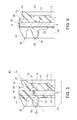
figure 4 illustrates on reduced scale a plan view of an annular component of the sealing assembly infigure 1 and 2 ; -
figures 5 and6 illustrate on enlarged scale the same detail infigure 3 , but according to sections taken along plotting planes V-V and VI-VI, as shown infigure 4 ; and -
figure 7 shows a detail on enlarged scale of the component infigure 4 . - With reference to
figures 1 and 2 ,reference numeral 1 indicates as a whole a low friction sealing assembly, in particular designed to be mounted on and become an integral part of a rolling bearing 2, especially but not exclusively of the so-called SRB (Spherical Roller Bearing) type. - The
sealing assembly 1 can be inserted in use between theouter ring 3 and theinner ring 4 of the rolling bearing 2 to protect the rolling bodies, known and not shown for the sake of simplicity, from external contaminants (in SRB bearings constituted by two crowns of rollers) interposed between theouter ring 3 and theinner ring 4 to make them relatively rotational with low friction, as well as to retain possible lubricant between therings rings sealing assembly 1 are symmetric with respect to a symmetry axis A, which is in common to the bearing 2 and thesealing assembly 1, when therings - More in general, the
sealing assembly 1 can be inserted between any two mechanical members orelements annular gap 5 enclosed between theelements - The
sealing assembly 1 comprises anannular metal insert 6 and anannular seal 7 made of elastomeric material which has been constrained integrally in one piece to themetal insert 6, for instance and preferably by bonding during the step of vulcanizing, according to a compression co-molding process of theseal 7 onto themetal insert 6, known in the art and which therefore is not described in detail for the sake of simplicity. - The
annular seal 7 comprises at least one elastically deformable firstannular lip 8, which radially extends in cantilever manner from a firstannular edge 9 of themetal insert 6 and anannular coupling portion 10 arranged on a secondannular edge 11 of themetal insert 6, opposite to the firstannular edge 9. - The
lip 8, which is intended in use to perform a dynamic sealing action on one of themembers inner ring 4, is formed entirely in elastomeric material and, according to a first aspect of the invention, is substantially C-shaped in radial section having aconcavity 12 facing the same side of thefirst face 13 of themetallic insert 6. - The
annular lip 8 is completely free of support by themetal insert 6, so as to be able to bend elastically in use both in radial and axial direction, folding towards itsconcavity 12 and ends with afree end 14 which, in the illustrated example, faces towards the symmetry axis A and is intended to cooperate in sliding manner with theinner ring 4. - The
coupling portion 10 is intended to allow the angular coupling of thesealing assembly 1 with the other element in relative rotation, in the case in point with theouter ring 3, and to perform a static sealing action thereon. For this purpose, thecoupling portion 10, according to a known arrangement, is provided with at least one elastically deformable second lip belonging to theseal 7. - According to a further aspect of the invention, the
coupling portion 10 is provided, in combination, with three elastically deformableannular lips coupling portion 10 on the side opposite to themetal insert 6; in particular, asecond lip 15 and athird lip 16 of theseal 7 extend in cantilever manner from thecoupling portion 10 in opposite directions, thelip 15 on the side of thefirst face 13 of themetal insert 6 and thelip 16 on the side of thesecond face 18, opposite to thefirst face 13, of themetal insert 6; thelips figure 1 ), in which they are aligned substantially along an oblique straight line R1 with respect to the symmetry axis A of thesealing assembly 1. - According to the embodiment shown, the
metal insert 6 is incorporated at least in part in theannular seal 7, which covers thefirst face 13 and also covers, passing over them, both the first and the secondannular edge - According to a further aspect of the invention, the second
annular edge 11 of themetal insert 6 is circumferentially provided (figures 4 and 7 ) with a plurality ofindentations 19, each having a radial depth substantially equal to the radial extension of the coupling portion 10 (figure 3 ), so that the secondannular edge 11 extends alternatively in thecoupling portion 10 with its firstcircumferential stretches 20, and substantially outside thecoupling portion 10 with its secondcircumferential stretches 21. In particular, at theradial indentations 19, the secondannular edge 11 ends in radial direction by means of itscircumferential stretches 21, substantially at aroot portion 22 of the annular lip 16 (figures 2 and3 ). - According to another, non-secondary aspect of the invention, the
coupling portion 10 is provided, in annular positions different from those occupied by thecircumferential indentations 19 of theannular edge 11 and, thus only at selectedstretches 20, with a first pair of radial slots 23 (figure 6 ), aligned and diametrically opposite to each other, which interrupt the circumferential continuity of thecoupling portion 10 for the entire radial extension thereof and which are obtained on the side of theannular lip 15, radially cutting also theannular lip 15 itself, and with a second pair of radial slots 23' (figure 5 ), aligned and diametrically opposite to each other, which also interrupt the circumferential continuity of thecoupling portion 10 for the entire radial extension thereof and are obtained on the side of theannular lips lips - The radial slots 23' are obtained in an offset and different position with respect to that occupied by the
slots 23 and in particular and preferably arranged at a right angle with respect to the angular position of theradial slots 23. Theseradial slots 23 and 23' angularly offset with respect to one another allow to release possible overpressure (e.g. caused by the heating of the lubricant grease with a consequent evaporation of part of its components) outside the bearing 2, in particular outside theannular gap 5, without causing the movement of theseal 1 and without the static action exerted by thecoupling portion 10 in use coming less. - As shown (
figure 3 ), thelips free end 24 thereof oflip 15 and a sealingfree end 25 oflip 16; the rotation centers C of thelips sealing assembly 1. - According to the preferred, but not limiting embodiment of the invention illustrated in the accompanying figures, the first annular edge of the
metal insert 6 is a radiallyinner edge 9 thereof and the second annular edge is a radiallyouter edge 11 thereof; in this case, the oblique straight line R1 along which thelips face 13 of themetal insert 6, i.e. converges towards axis A on the side of theopposite face 18. - In all cases, the
lips free ends 25 for thelip lip 17, both facing towards the side of thesecond face 18 of theannular insert 6, arranged substantially flush with an extradox portion 27 (figure 2 ) of the C-shaped lip 8,portion 27 opposite to theconcavity 12; furthermore, thelip 17 is substantially oriented obliquely and has the sealingfree end 26 thereof facing towards the symmetry axis A on the side of theface 18. - Furthermore, the
lip 16 and thelip 17, in undeformed conditions such as those illustrated in figures from 2,3 and 5,6, are substantially parallel to one another and thelip 17 is carried by the radiallyoutermost coupling portion 10 with respect to thelip 16. Conversely, thelip 15 is carried by thecoupling portion 10 to a radial position such as to be arranged substantially radially between thelips lips metal insert 6. - Finally, according to a further aspect of the invention, the
coupling portion 10 has an annularaxial shoulder 28 on the side of thelip 15 arranged radially on the outside of, and immediately adjacent to, thesecond lip 15; theannular shoulder 28 is further substantially aligned in radial direction with aroot portion 29 of the lip 17 (figures 3 and6 ) and is supported, even though only at all thesestretches 20, by theedge 11 of themetal insert 6, which contributes in all cases to providing a given rigidity to theshoulder 28. - With reference again to
figure 1 , the invention also relates to the rollingbearing 1, in particular when of the SRB type, provided with two sealing assemblies 1 - as those described - mounted on the opposite axial ends, of which only one is shown infigure 1 , the other being symmetric. - According to the invention, the
coupling portion 10 engages anannular seat 30 obtained radially on the inside of theouter ring 3 and theannular lip 8 cooperates in a sliding manner with anoblique sealing surface 31 of theinner ring 4 obtained radially on the outside of theinner ring 4 and oriented along an oblique direction R2 with respect to the symmetry axis A of thesealing assembly 1. - The
annular seat 30 of theouter ring 3 is delimited between a first radiallyinner edge 32 thereof against which theannular lip 17 of thesealing assembly 1 cooperates so as to be deformed towards theinner ring 4, and a second radiallyinner edge 33 thereof, opposite to the first, against which thelip 17, by deforming by effect of the shape of theseat 30, pushes the axialannular shoulder 28 of thecoupling portion 10 facing towards thelip 15 in use; in this manner, thesealing assembly 1 is axially blocked in theseat 30 from both sides. - Furthermore, the
annular seat 30 is externally delimited by a pair ofradial shoulders second lip 15 and thethird lip 16, respectively, cooperate on the opposite side; the pair ofradial shoulders outer ring 3 so as to be aligned along a second oblique direction R1', opposite to direction R2 and parallel to the first straight line R1; directions R2 and R1' converge towards the inside of theouter ring 3, and thus towards theannular gap 5, so as to constitute, on one side, a lead-in for the assembly of thesealing assembly 1 in theseat 30 and on the other side, to balance the dynamic thrusts of theseal 7, thrusts which are relieved onto thelips shoulders entire sealing assembly 1 always in the correct position, with the metal insert 6 substantially perpendicular to the symmetry axis of thering 3 also when the latter does not coincide with that of thering 4, e.g. by effect of an offsetting. - All the objects of the invention are thus reached.
Claims (10)
- A sealing assembly (1), in particular for rolling bearings of the SRB type, comprising an annular metal insert (6) and an annular seal made of elastomeric material (7), integrally constrained in one piece to the metal insert (6) for bonding during the step of vulcanizing; the annular seal (7) comprising at least one elastically deformable first annular lip (8), which radially extends in cantilever manner from a first annular edge (9) of the metal insert, the first lip (8) being entirely formed in elastomeric material, and an annular coupling portion (10) arranged on a second annular edge (11) of the metal insert, opposite to the first annular edge, the coupling portion (10) being provided with at least one elastically deformable second annular lip (15), which extends in cantilever manner from the coupling portion on the side opposite to the metal insert (6); wherein:i - the first annular lip (8) is substantially C-shaped in radial section having a concavity (12) facing the same side of a first face (13) of the metal insert;ii - the coupling portion (10) is provided with an elastically deformable third (16) and fourth (17) annular lip, which extend in cantilever manner from the coupling portion (10) on the side opposite to the metal insert (6);iii - the second (15) and the third (16) lips extend in cantilever manner in opposite directions, the second lip (15) from the side of the first face (13) and the third lip (16) from the side of a second face (18), opposite to the first, of the metal insert (6) and are adapted to take in use a deformed conformation in which they are substantially aligned along an oblique straight line (R1) with respect to a symmetry axis (A) of the sealing assembly; characterized in that, in combinationiv - the second annular edge (11) of the metal insert is circumferentially provided with a plurality of indentations (19), each having a radial depth substantially equal to the radial extension of the coupling portion (10), so that the second annular edge (11) extends, alternatively, inside and substantially outside the coupling portion (10).
- A sealing assembly according to claim 1, characterized in that the metal insert (6) is embedded at least in part in the annular seal (7), which covers the first face (13) and also covers both the first and the second annular edges (9,11) by passing over them.
- A sealing assembly (100) according to claim 1 or 2, characterized in that at the radial indentations (19), the second annular edge (11) ends in radial direction substantially at a root portion (22) of the third annular lip (16).
- A sealing assembly according to any one of the preceding claims, characterized in that the coupling portion (10) is provided, in angular positions different from those occupied by the circumferential indentations (19) of the second annular edge of the metal insert:with a first pair of reciprocally aligned and diametrically opposite radial slots (23), which interrupt the circumferential continuity of the coupling portion (10) for the radial extension thereof, and which are obtained on the side of the second annular lip (15) so as to radially cut also the second annular lip;with a second pair of reciprocally aligned and diametrically opposite radial slots (23'), which interrupt the circumferential continuity of the coupling portion (10) for the whole radial extension thereof, and which are obtained on the side of the third and fourth annular lips (16,17), so as to radially cut also the third and fourth annular lip;the radial slots of the second pair (23') being obtained in an angular position different, and preferably arranged at a straight angle, with respect to the angular position of the radial slots of the first pair (23).
- A sealing assembly according to any one of the preceding claims, characterized in that the first annular lip (8) is completely free of support by the metal insert (6) so as to be able to bend elastically both in radial and axial direction, thus bending towards the concavity (12) thereof.
- A sealing assembly according to any one of the preceding claims, characterized in that the second and the third lips (15,16) are shaped so as to have, each, a respective rotation center (C) for a sealing free end (24,25) thereof, which rotation centers (C) of the second and third lips are arranged on the oblique line (R1) converging towards the symmetry axis (A) of the sealing assembly.
- A sealing assembly according to any one of the preceding claims, characterized in that the first annular edge (9) of the metal insert is a radially inner edge thereof, and the second annular edge (11) is a radially outer edge thereof, the oblique straight line (R1) along which the second and the third annular lips (15,16) are substantially aligned being converging towards the symmetry axis (A) on the side opposite to the first face (13) of the metal insert.
- A sealing assembly according to claim 7, characterized in that the third and the fourth annular lip (16,17) have respective sealing free ends (25,26) facing the side of the second face (18) of the annular insert and arranged substantially flush with an extradox portion (27) of the first lip (8), opposite to the concavity (12) thereof; the fourth lip (17) being oriented obliquely with the sealing free end (26) thereof toward the symmetry axis (A) on the side of second face (18) of the annular insert; the third and the fourth annular lip (16,17) in non-deformed conditions being substantially parallel to each other, the fourth lip (17) being carried by the coupling portion (10) on the outermost radial side with respect to the third lip (16).
- A sealing assembly according to claim 8, characterized in that the second lip (15) is carried by the coupling portion (10) in a radial position such as to be arranged substantially between the third and the fourth lips (16,17), but on the side opposite to the third and fourth lips with respect to the metal insert (6); on the side of the second lip (15) the coupling portion (10) being provided with an annular axial shoulder (28) arranged radially farther of, and immediately adjacent to, the second lip (15), the annular axial shoulder (28) being further substantially aligned, in radial direction, with a root portion (29) of the fourth lip (17).
- A rolling bearing (2) comprising an outer ring (3), an inner ring (4) and at least one sealing assembly (1) comprising an annular metal insert (6) and an annular seal made of elastomeric material (7), integrally constrained in one piece to the metal insert (6); the annular seal (7) comprising at least one elastically deformable first annular lip (8), which radially extends in cantilever manner from a first annular edge (9) of the metal insert, the first lip (8) being entirely formed in elastomeric material, and an annular coupling portion (10) arranged on a second annular edge (11) of the metal insert, opposite to the first annular edge, the coupling portion (10) being provided with at least one elastically deformable second annular lip (15), which extends in cantilever manner from the coupling portion on the side opposite to the metal insert (6); wherein the first annular lip (8) is substantially C-shaped in radial section having a concavity (12) facing the same side of a first face (13) of the metal insert; the coupling portion (10) is provided with an elastically deformable third (16) and fourth (17) annular lip, which extend in cantilever manner from the coupling portion (10) on the side opposite to the metal insert (6); the second (15) and the third (16) lips extend in cantilever manner in opposite directions, the second lip (15) from the side of the first face (13) and the third lip (16) from the side of a second face (18), opposite to the first, of the metal insert (6) and are adapted to take in use a deformed conformation in which they are substantially aligned along an oblique straight line (R1) with respect to a symmetry axis (A) of the sealing assembly, characterized in that the coupling portion (10) engages an annular seat (30) obtained radially on the inside of the outer ring (3) and the first annular lip (8) cooperates in sliding manner with an oblique sealing surface (31) of the inner ring (4) obtained radially on the outside of the inner ring (4) and oriented along a first oblique direction (R2) with respect to the symmetry axis (A) of the sealing assembly; the annular seat (30) of the outer ring being delimited between a radially inner first edge (32) thereof against which the fourth annular lip (17) of the sealing assembly cooperates so as to be deformed towards the inner ring (4) and a radially inner second edge (33) thereof, opposite to the first, against which the fourth lip (17) pushes an annular axial shoulder (28) of the coupling portion (10) facing towards the second lip (15); the annular seat (30) being further externally delimited by a pair of radial shoulders (34,35) against which the second (15) and the third (16) annular lip cooperate on the opposite side; the pair of radial shoulders (43,35) being aligned along a second oblique direction (R1'), opposite to first, the first and the second oblique direction (R2,R1') converging towards the inside of the outer ring (3).
Applications Claiming Priority (1)
| Application Number | Priority Date | Filing Date | Title |
|---|---|---|---|
| ITTO20140686 | 2014-09-01 |
Publications (2)
| Publication Number | Publication Date |
|---|---|
| EP2990674A1 true EP2990674A1 (en) | 2016-03-02 |
| EP2990674B1 EP2990674B1 (en) | 2018-04-11 |
Family
ID=51753405
Family Applications (1)
| Application Number | Title | Priority Date | Filing Date |
|---|---|---|---|
| EP15178948.4A Not-in-force EP2990674B1 (en) | 2014-09-01 | 2015-07-29 | Sealing assembly, in particular for spherical roller bearings |
Country Status (1)
| Country | Link |
|---|---|
| EP (1) | EP2990674B1 (en) |
Cited By (7)
| Publication number | Priority date | Publication date | Assignee | Title |
|---|---|---|---|---|
| CN106090027A (en) * | 2016-08-08 | 2016-11-09 | 浙江天马轴承有限公司 | A kind of sealing ring sealing self-aligning roller bearing |
| FR3060678A1 (en) * | 2016-12-20 | 2018-06-22 | Ntn-Snr Roulements | BEARING BEARING |
| DE102018221928A1 (en) | 2018-12-17 | 2020-06-18 | Aktiebolaget Skf | System with a roller bearing |
| US10731743B2 (en) * | 2011-11-16 | 2020-08-04 | Roller Bearing Company Of America, Inc. | Cam follower and yoke roller assemblies |
| CN113217547A (en) * | 2021-05-14 | 2021-08-06 | 人本股份有限公司 | Sealing element and double-row angular contact ball bearing |
| IT202200014851A1 (en) * | 2022-07-15 | 2024-01-15 | Skf Ab | ROLLING ELEMENT BEARING UNIT |
| US20240019000A1 (en) * | 2022-07-15 | 2024-01-18 | Aktiebolaget Skf | Bearing unit with rolling bodies |
Citations (2)
| Publication number | Priority date | Publication date | Assignee | Title |
|---|---|---|---|---|
| US3473856A (en) * | 1967-08-25 | 1969-10-21 | Skf Ind Inc | Seal for bearing |
| EP0708263A1 (en) | 1994-10-18 | 1996-04-24 | SKF Industrial Trading & Development Company, B.V. | Rolling bearing with oil seal |
-
2015
- 2015-07-29 EP EP15178948.4A patent/EP2990674B1/en not_active Not-in-force
Patent Citations (2)
| Publication number | Priority date | Publication date | Assignee | Title |
|---|---|---|---|---|
| US3473856A (en) * | 1967-08-25 | 1969-10-21 | Skf Ind Inc | Seal for bearing |
| EP0708263A1 (en) | 1994-10-18 | 1996-04-24 | SKF Industrial Trading & Development Company, B.V. | Rolling bearing with oil seal |
Cited By (12)
| Publication number | Priority date | Publication date | Assignee | Title |
|---|---|---|---|---|
| US10731743B2 (en) * | 2011-11-16 | 2020-08-04 | Roller Bearing Company Of America, Inc. | Cam follower and yoke roller assemblies |
| CN106090027A (en) * | 2016-08-08 | 2016-11-09 | 浙江天马轴承有限公司 | A kind of sealing ring sealing self-aligning roller bearing |
| FR3060678A1 (en) * | 2016-12-20 | 2018-06-22 | Ntn-Snr Roulements | BEARING BEARING |
| DE102018221928A1 (en) | 2018-12-17 | 2020-06-18 | Aktiebolaget Skf | System with a roller bearing |
| US11002317B2 (en) | 2018-12-17 | 2021-05-11 | Aktiebolaget Skf | System with a rolling bearing |
| CN113217547A (en) * | 2021-05-14 | 2021-08-06 | 人本股份有限公司 | Sealing element and double-row angular contact ball bearing |
| CN113217547B (en) * | 2021-05-14 | 2022-04-22 | 人本股份有限公司 | Sealing element and double-row angular contact ball bearing |
| IT202200014851A1 (en) * | 2022-07-15 | 2024-01-15 | Skf Ab | ROLLING ELEMENT BEARING UNIT |
| EP4306815A1 (en) * | 2022-07-15 | 2024-01-17 | Aktiebolaget SKF | Bearing unit with rolling bodies |
| US20240019000A1 (en) * | 2022-07-15 | 2024-01-18 | Aktiebolaget Skf | Bearing unit with rolling bodies |
| US12398759B2 (en) * | 2022-07-15 | 2025-08-26 | Aktiebolaget Skf | Bearing unit with rolling bodies |
| US12404899B2 (en) | 2022-07-15 | 2025-09-02 | Aktiebolaget Skf | Bearing unit with rolling bodies |
Also Published As
| Publication number | Publication date |
|---|---|
| EP2990674B1 (en) | 2018-04-11 |
Similar Documents
| Publication | Publication Date | Title |
|---|---|---|
| EP2990674B1 (en) | Sealing assembly, in particular for spherical roller bearings | |
| US20160363169A1 (en) | Rolling bearing with seal | |
| JP6683467B2 (en) | Rolling bearing with sealing flange | |
| WO2016179608A3 (en) | Intershaft seal with asymmetric sealing ring | |
| EP2857704A1 (en) | Cartridge seal with annular lips forming a labyrinth packing, in particular for rolling bearings | |
| EP3332137A1 (en) | Angular contact roller bearing and method and device for the assembly thereof | |
| CN105317847B (en) | Inserts, seals, universal joints and bearing bushes for rolling bearing seals | |
| US9422983B2 (en) | Roller bearing with modular shoulders | |
| US20170138404A1 (en) | Rolling bearing | |
| JP6028409B2 (en) | Self-aligning roller bearing with sealing device and manufacturing method thereof | |
| EP2891809B1 (en) | Bush bearing, and rack-and-pinion steering device adapted for use in automobile and using same | |
| US10119617B2 (en) | Sealing device | |
| JP6790555B2 (en) | Rolling bearing | |
| JP2016102514A5 (en) | ||
| EP3034899A1 (en) | Seal for self aligning roller bearing | |
| JP6817698B2 (en) | Rolling bearings with sealing flanges | |
| EP3336370A1 (en) | Cam follower and yoke roller assemblies | |
| EP3421828A1 (en) | Roller bearing | |
| JP2017088172A5 (en) | ||
| EP3009697A1 (en) | Rolling bearing assembly and rotary machine comprising such a rolling bearing assembly | |
| WO2016091560A1 (en) | A roller bearing as well as a cage suitable for such a roller bearing | |
| EP2975277B1 (en) | Bearing assembly having surface protrusions and a seal | |
| JP2015098878A (en) | Bearing device | |
| JP2018004062A (en) | Rolling bearing | |
| EP3347610B1 (en) | Bearing element |
Legal Events
| Date | Code | Title | Description |
|---|---|---|---|
| PUAI | Public reference made under article 153(3) epc to a published international application that has entered the european phase |
Free format text: ORIGINAL CODE: 0009012 |
|
| AK | Designated contracting states |
Kind code of ref document: A1 Designated state(s): AL AT BE BG CH CY CZ DE DK EE ES FI FR GB GR HR HU IE IS IT LI LT LU LV MC MK MT NL NO PL PT RO RS SE SI SK SM TR |
|
| AX | Request for extension of the european patent |
Extension state: BA ME |
|
| 17P | Request for examination filed |
Effective date: 20160901 |
|
| RBV | Designated contracting states (corrected) |
Designated state(s): AL AT BE BG CH CY CZ DE DK EE ES FI FR GB GR HR HU IE IS IT LI LT LU LV MC MK MT NL NO PL PT RO RS SE SI SK SM TR |
|
| GRAP | Despatch of communication of intention to grant a patent |
Free format text: ORIGINAL CODE: EPIDOSNIGR1 |
|
| STAA | Information on the status of an ep patent application or granted ep patent |
Free format text: STATUS: GRANT OF PATENT IS INTENDED |
|
| INTG | Intention to grant announced |
Effective date: 20171121 |
|
| GRAS | Grant fee paid |
Free format text: ORIGINAL CODE: EPIDOSNIGR3 |
|
| GRAA | (expected) grant |
Free format text: ORIGINAL CODE: 0009210 |
|
| STAA | Information on the status of an ep patent application or granted ep patent |
Free format text: STATUS: THE PATENT HAS BEEN GRANTED |
|
| AK | Designated contracting states |
Kind code of ref document: B1 Designated state(s): AL AT BE BG CH CY CZ DE DK EE ES FI FR GB GR HR HU IE IS IT LI LT LU LV MC MK MT NL NO PL PT RO RS SE SI SK SM TR |
|
| REG | Reference to a national code |
Ref country code: GB Ref legal event code: FG4D |
|
| REG | Reference to a national code |
Ref country code: CH Ref legal event code: EP |
|
| REG | Reference to a national code |
Ref country code: AT Ref legal event code: REF Ref document number: 988357 Country of ref document: AT Kind code of ref document: T Effective date: 20180415 |
|
| REG | Reference to a national code |
Ref country code: IE Ref legal event code: FG4D |
|
| REG | Reference to a national code |
Ref country code: DE Ref legal event code: R096 Ref document number: 602015009760 Country of ref document: DE |
|
| REG | Reference to a national code |
Ref country code: FR Ref legal event code: PLFP Year of fee payment: 4 |
|
| REG | Reference to a national code |
Ref country code: NL Ref legal event code: MP Effective date: 20180411 |
|
| REG | Reference to a national code |
Ref country code: LT Ref legal event code: MG4D |
|
| PG25 | Lapsed in a contracting state [announced via postgrant information from national office to epo] |
Ref country code: NL Free format text: LAPSE BECAUSE OF FAILURE TO SUBMIT A TRANSLATION OF THE DESCRIPTION OR TO PAY THE FEE WITHIN THE PRESCRIBED TIME-LIMIT Effective date: 20180411 |
|
| PG25 | Lapsed in a contracting state [announced via postgrant information from national office to epo] |
Ref country code: PL Free format text: LAPSE BECAUSE OF FAILURE TO SUBMIT A TRANSLATION OF THE DESCRIPTION OR TO PAY THE FEE WITHIN THE PRESCRIBED TIME-LIMIT Effective date: 20180411 Ref country code: LT Free format text: LAPSE BECAUSE OF FAILURE TO SUBMIT A TRANSLATION OF THE DESCRIPTION OR TO PAY THE FEE WITHIN THE PRESCRIBED TIME-LIMIT Effective date: 20180411 Ref country code: ES Free format text: LAPSE BECAUSE OF FAILURE TO SUBMIT A TRANSLATION OF THE DESCRIPTION OR TO PAY THE FEE WITHIN THE PRESCRIBED TIME-LIMIT Effective date: 20180411 Ref country code: BG Free format text: LAPSE BECAUSE OF FAILURE TO SUBMIT A TRANSLATION OF THE DESCRIPTION OR TO PAY THE FEE WITHIN THE PRESCRIBED TIME-LIMIT Effective date: 20180711 Ref country code: FI Free format text: LAPSE BECAUSE OF FAILURE TO SUBMIT A TRANSLATION OF THE DESCRIPTION OR TO PAY THE FEE WITHIN THE PRESCRIBED TIME-LIMIT Effective date: 20180411 Ref country code: NO Free format text: LAPSE BECAUSE OF FAILURE TO SUBMIT A TRANSLATION OF THE DESCRIPTION OR TO PAY THE FEE WITHIN THE PRESCRIBED TIME-LIMIT Effective date: 20180711 Ref country code: AL Free format text: LAPSE BECAUSE OF FAILURE TO SUBMIT A TRANSLATION OF THE DESCRIPTION OR TO PAY THE FEE WITHIN THE PRESCRIBED TIME-LIMIT Effective date: 20180411 Ref country code: SE Free format text: LAPSE BECAUSE OF FAILURE TO SUBMIT A TRANSLATION OF THE DESCRIPTION OR TO PAY THE FEE WITHIN THE PRESCRIBED TIME-LIMIT Effective date: 20180411 |
|
| PG25 | Lapsed in a contracting state [announced via postgrant information from national office to epo] |
Ref country code: GR Free format text: LAPSE BECAUSE OF FAILURE TO SUBMIT A TRANSLATION OF THE DESCRIPTION OR TO PAY THE FEE WITHIN THE PRESCRIBED TIME-LIMIT Effective date: 20180712 Ref country code: LV Free format text: LAPSE BECAUSE OF FAILURE TO SUBMIT A TRANSLATION OF THE DESCRIPTION OR TO PAY THE FEE WITHIN THE PRESCRIBED TIME-LIMIT Effective date: 20180411 Ref country code: HR Free format text: LAPSE BECAUSE OF FAILURE TO SUBMIT A TRANSLATION OF THE DESCRIPTION OR TO PAY THE FEE WITHIN THE PRESCRIBED TIME-LIMIT Effective date: 20180411 Ref country code: RS Free format text: LAPSE BECAUSE OF FAILURE TO SUBMIT A TRANSLATION OF THE DESCRIPTION OR TO PAY THE FEE WITHIN THE PRESCRIBED TIME-LIMIT Effective date: 20180411 |
|
| REG | Reference to a national code |
Ref country code: AT Ref legal event code: MK05 Ref document number: 988357 Country of ref document: AT Kind code of ref document: T Effective date: 20180411 |
|
| PG25 | Lapsed in a contracting state [announced via postgrant information from national office to epo] |
Ref country code: PT Free format text: LAPSE BECAUSE OF FAILURE TO SUBMIT A TRANSLATION OF THE DESCRIPTION OR TO PAY THE FEE WITHIN THE PRESCRIBED TIME-LIMIT Effective date: 20180813 |
|
| REG | Reference to a national code |
Ref country code: DE Ref legal event code: R097 Ref document number: 602015009760 Country of ref document: DE |
|
| PG25 | Lapsed in a contracting state [announced via postgrant information from national office to epo] |
Ref country code: CZ Free format text: LAPSE BECAUSE OF FAILURE TO SUBMIT A TRANSLATION OF THE DESCRIPTION OR TO PAY THE FEE WITHIN THE PRESCRIBED TIME-LIMIT Effective date: 20180411 Ref country code: RO Free format text: LAPSE BECAUSE OF FAILURE TO SUBMIT A TRANSLATION OF THE DESCRIPTION OR TO PAY THE FEE WITHIN THE PRESCRIBED TIME-LIMIT Effective date: 20180411 Ref country code: SK Free format text: LAPSE BECAUSE OF FAILURE TO SUBMIT A TRANSLATION OF THE DESCRIPTION OR TO PAY THE FEE WITHIN THE PRESCRIBED TIME-LIMIT Effective date: 20180411 Ref country code: EE Free format text: LAPSE BECAUSE OF FAILURE TO SUBMIT A TRANSLATION OF THE DESCRIPTION OR TO PAY THE FEE WITHIN THE PRESCRIBED TIME-LIMIT Effective date: 20180411 Ref country code: AT Free format text: LAPSE BECAUSE OF FAILURE TO SUBMIT A TRANSLATION OF THE DESCRIPTION OR TO PAY THE FEE WITHIN THE PRESCRIBED TIME-LIMIT Effective date: 20180411 Ref country code: DK Free format text: LAPSE BECAUSE OF FAILURE TO SUBMIT A TRANSLATION OF THE DESCRIPTION OR TO PAY THE FEE WITHIN THE PRESCRIBED TIME-LIMIT Effective date: 20180411 |
|
| PLBE | No opposition filed within time limit |
Free format text: ORIGINAL CODE: 0009261 |
|
| STAA | Information on the status of an ep patent application or granted ep patent |
Free format text: STATUS: NO OPPOSITION FILED WITHIN TIME LIMIT |
|
| PG25 | Lapsed in a contracting state [announced via postgrant information from national office to epo] |
Ref country code: IT Free format text: LAPSE BECAUSE OF FAILURE TO SUBMIT A TRANSLATION OF THE DESCRIPTION OR TO PAY THE FEE WITHIN THE PRESCRIBED TIME-LIMIT Effective date: 20180411 Ref country code: SM Free format text: LAPSE BECAUSE OF FAILURE TO SUBMIT A TRANSLATION OF THE DESCRIPTION OR TO PAY THE FEE WITHIN THE PRESCRIBED TIME-LIMIT Effective date: 20180411 |
|
| REG | Reference to a national code |
Ref country code: CH Ref legal event code: PL |
|
| 26N | No opposition filed |
Effective date: 20190114 |
|
| PG25 | Lapsed in a contracting state [announced via postgrant information from national office to epo] |
Ref country code: LU Free format text: LAPSE BECAUSE OF NON-PAYMENT OF DUE FEES Effective date: 20180729 Ref country code: MC Free format text: LAPSE BECAUSE OF FAILURE TO SUBMIT A TRANSLATION OF THE DESCRIPTION OR TO PAY THE FEE WITHIN THE PRESCRIBED TIME-LIMIT Effective date: 20180411 |
|
| REG | Reference to a national code |
Ref country code: BE Ref legal event code: MM Effective date: 20180731 |
|
| PG25 | Lapsed in a contracting state [announced via postgrant information from national office to epo] |
Ref country code: CH Free format text: LAPSE BECAUSE OF NON-PAYMENT OF DUE FEES Effective date: 20180731 Ref country code: LI Free format text: LAPSE BECAUSE OF NON-PAYMENT OF DUE FEES Effective date: 20180731 |
|
| REG | Reference to a national code |
Ref country code: IE Ref legal event code: MM4A |
|
| PG25 | Lapsed in a contracting state [announced via postgrant information from national office to epo] |
Ref country code: SI Free format text: LAPSE BECAUSE OF FAILURE TO SUBMIT A TRANSLATION OF THE DESCRIPTION OR TO PAY THE FEE WITHIN THE PRESCRIBED TIME-LIMIT Effective date: 20180411 Ref country code: BE Free format text: LAPSE BECAUSE OF NON-PAYMENT OF DUE FEES Effective date: 20180731 |
|
| PG25 | Lapsed in a contracting state [announced via postgrant information from national office to epo] |
Ref country code: IE Free format text: LAPSE BECAUSE OF NON-PAYMENT OF DUE FEES Effective date: 20180729 |
|
| PG25 | Lapsed in a contracting state [announced via postgrant information from national office to epo] |
Ref country code: MT Free format text: LAPSE BECAUSE OF NON-PAYMENT OF DUE FEES Effective date: 20180729 |
|
| GBPC | Gb: european patent ceased through non-payment of renewal fee |
Effective date: 20190729 |
|
| PG25 | Lapsed in a contracting state [announced via postgrant information from national office to epo] |
Ref country code: TR Free format text: LAPSE BECAUSE OF FAILURE TO SUBMIT A TRANSLATION OF THE DESCRIPTION OR TO PAY THE FEE WITHIN THE PRESCRIBED TIME-LIMIT Effective date: 20180411 |
|
| PG25 | Lapsed in a contracting state [announced via postgrant information from national office to epo] |
Ref country code: GB Free format text: LAPSE BECAUSE OF NON-PAYMENT OF DUE FEES Effective date: 20190729 |
|
| PG25 | Lapsed in a contracting state [announced via postgrant information from national office to epo] |
Ref country code: HU Free format text: LAPSE BECAUSE OF FAILURE TO SUBMIT A TRANSLATION OF THE DESCRIPTION OR TO PAY THE FEE WITHIN THE PRESCRIBED TIME-LIMIT; INVALID AB INITIO Effective date: 20150729 Ref country code: MK Free format text: LAPSE BECAUSE OF NON-PAYMENT OF DUE FEES Effective date: 20180411 Ref country code: CY Free format text: LAPSE BECAUSE OF FAILURE TO SUBMIT A TRANSLATION OF THE DESCRIPTION OR TO PAY THE FEE WITHIN THE PRESCRIBED TIME-LIMIT Effective date: 20180411 |
|
| PG25 | Lapsed in a contracting state [announced via postgrant information from national office to epo] |
Ref country code: IS Free format text: LAPSE BECAUSE OF FAILURE TO SUBMIT A TRANSLATION OF THE DESCRIPTION OR TO PAY THE FEE WITHIN THE PRESCRIBED TIME-LIMIT Effective date: 20180811 |
|
| PGFP | Annual fee paid to national office [announced via postgrant information from national office to epo] |
Ref country code: DE Payment date: 20220727 Year of fee payment: 8 |
|
| PGFP | Annual fee paid to national office [announced via postgrant information from national office to epo] |
Ref country code: FR Payment date: 20220725 Year of fee payment: 8 |
|
| P01 | Opt-out of the competence of the unified patent court (upc) registered |
Effective date: 20230513 |
|
| REG | Reference to a national code |
Ref country code: DE Ref legal event code: R119 Ref document number: 602015009760 Country of ref document: DE |
|
| PG25 | Lapsed in a contracting state [announced via postgrant information from national office to epo] |
Ref country code: DE Free format text: LAPSE BECAUSE OF NON-PAYMENT OF DUE FEES Effective date: 20240201 |
|
| PG25 | Lapsed in a contracting state [announced via postgrant information from national office to epo] |
Ref country code: FR Free format text: LAPSE BECAUSE OF NON-PAYMENT OF DUE FEES Effective date: 20230731 |