EP2990635A1 - Connector arrangement - Google Patents
Connector arrangement Download PDFInfo
- Publication number
- EP2990635A1 EP2990635A1 EP14182078.7A EP14182078A EP2990635A1 EP 2990635 A1 EP2990635 A1 EP 2990635A1 EP 14182078 A EP14182078 A EP 14182078A EP 2990635 A1 EP2990635 A1 EP 2990635A1
- Authority
- EP
- European Patent Office
- Prior art keywords
- locking ring
- locking
- connector
- wing
- connector arrangement
- Prior art date
- Legal status (The legal status is an assumption and is not a legal conclusion. Google has not performed a legal analysis and makes no representation as to the accuracy of the status listed.)
- Granted
Links
Images



Classifications
-
- F—MECHANICAL ENGINEERING; LIGHTING; HEATING; WEAPONS; BLASTING
- F02—COMBUSTION ENGINES; HOT-GAS OR COMBUSTION-PRODUCT ENGINE PLANTS
- F02M—SUPPLYING COMBUSTION ENGINES IN GENERAL WITH COMBUSTIBLE MIXTURES OR CONSTITUENTS THEREOF
- F02M35/00—Combustion-air cleaners, air intakes, intake silencers, or induction systems specially adapted for, or arranged on, internal-combustion engines
- F02M35/10—Air intakes; Induction systems
- F02M35/10091—Air intakes; Induction systems characterised by details of intake ducts: shapes; connections; arrangements
- F02M35/10144—Connections of intake ducts to each other or to another device
-
- F—MECHANICAL ENGINEERING; LIGHTING; HEATING; WEAPONS; BLASTING
- F01—MACHINES OR ENGINES IN GENERAL; ENGINE PLANTS IN GENERAL; STEAM ENGINES
- F01N—GAS-FLOW SILENCERS OR EXHAUST APPARATUS FOR MACHINES OR ENGINES IN GENERAL; GAS-FLOW SILENCERS OR EXHAUST APPARATUS FOR INTERNAL-COMBUSTION ENGINES
- F01N13/00—Exhaust or silencing apparatus characterised by constructional features
- F01N13/18—Construction facilitating manufacture, assembly, or disassembly
- F01N13/1805—Fixing exhaust manifolds, exhaust pipes or pipe sections to each other, to engine or to vehicle body
-
- F—MECHANICAL ENGINEERING; LIGHTING; HEATING; WEAPONS; BLASTING
- F16—ENGINEERING ELEMENTS AND UNITS; GENERAL MEASURES FOR PRODUCING AND MAINTAINING EFFECTIVE FUNCTIONING OF MACHINES OR INSTALLATIONS; THERMAL INSULATION IN GENERAL
- F16L—PIPES; JOINTS OR FITTINGS FOR PIPES; SUPPORTS FOR PIPES, CABLES OR PROTECTIVE TUBING; MEANS FOR THERMAL INSULATION IN GENERAL
- F16L37/00—Couplings of the quick-acting type
- F16L37/24—Couplings of the quick-acting type in which the connection is made by inserting one member axially into the other and rotating it to a limited extent, e.g. with bayonet-action
- F16L37/244—Couplings of the quick-acting type in which the connection is made by inserting one member axially into the other and rotating it to a limited extent, e.g. with bayonet-action the coupling being co-axial with the pipe
- F16L37/252—Couplings of the quick-acting type in which the connection is made by inserting one member axially into the other and rotating it to a limited extent, e.g. with bayonet-action the coupling being co-axial with the pipe the male part having lugs on its periphery penetrating into the corresponding slots provided in the female part
-
- F—MECHANICAL ENGINEERING; LIGHTING; HEATING; WEAPONS; BLASTING
- F01—MACHINES OR ENGINES IN GENERAL; ENGINE PLANTS IN GENERAL; STEAM ENGINES
- F01N—GAS-FLOW SILENCERS OR EXHAUST APPARATUS FOR MACHINES OR ENGINES IN GENERAL; GAS-FLOW SILENCERS OR EXHAUST APPARATUS FOR INTERNAL-COMBUSTION ENGINES
- F01N2450/00—Methods or apparatus for fitting, inserting or repairing different elements
- F01N2450/26—Methods or apparatus for fitting, inserting or repairing different elements by bayonet fittings
Definitions
- the invention relates to a connector arrangement comprising a tubular connector element configured for mounting on an inlet of a further component and an annular locking ring arranged around an end section of the connector element.
- the invention can be used in different types of arrangements of conduits or tubular connections in which there is a need for connecting a tubular connector element to a further component.
- the invention can be used in an engine compartment of a vehicle, for connecting various conduits between components in said engine compartment.
- conduits and tubular elements between various components of the engine arrangement, such as inlets and outlets of a compressor, a turbo device, a catalytic converter or other parts of the engine arrangement.
- tubular conduits and connections for such conduits should be of high quality and also be quick and easy to mount, i.e. during the actual assembly of the engine arrangement or the entire vehicle.
- An example of such connections is the inlet and outlet conduits of a turbo device.
- an object of the invention is to provide a connector arrangement which allows an improved mounting procedure as compared with the above-mentioned prior art solutions while providing a secure connection.
- a connector arrangement comprising a tubular connector element configured for mounting on an inlet of a further component and an annular locking ring arranged around an end section of the connector element.
- the locking ring comprises at least two wing elements extending in a radial direction and configured for being inserted into corresponding guide sections in said inlet, and in that at least one of said wing elements constitutes a locking wing with a resilient protrusion extending along the periphery of the locking ring and cooperating with a locking recess in a corresponding guide section upon rotating said locking ring in relation to said inlet.
- the invention provides certain advantages over previously known technology, primarily due to the fact that it leads to a quick and easy mounting procedure which in turn simplifies the assembly of the engine arrangement.
- the resilient protrusion is configured so that its tip extends further in a radial direction than said locking wing. In this manner, the resilient protrusion may be bent and then snap back during locking of the locking wing.
- the locking recess has a radially extending end wall which serves to lock the protruding element.
- the protruding element comprises a first section which connects to the locking wing and has a width which is less than the width of said locking wing. In this manner, the protruding element will generate a loud "click” when it is locked. This clearly audible "click” sound will serve as an acknowledgement for the person who is locking the connector device that the locking ring is locked.
- the protruding element comprises a section extending in the axial direction of the connector element and serving as a means for unlocking said connector arrangement when being pushed.
- the locking ring also comprises a radially extending stop element between the protruding element and the locking ring and constituting a limit for flexing said protruding element in the radial direction. This prevents the protruding element from being broken during unlocking.
- the locking ring is freely rotatable around the connector element. According to a further embodiment, the locking ring is fixedly mounted on said connector element.
- the invention can be applied in different types of vehicles, such as cars, trucks, and buses. Although the invention will be described with respect to an application in the form of a conventional engine arrangement, the invention is not restricted to such arrangement only but can generally be used in any type of arrangement involving tubular connector elements which should be locked to each other.
- FIG. 1 With initial reference to Fig. 1 , there is shown a simplified side view of an engine arrangement 1 in a vehicle.
- the engine arrangement 1 comprises an internal combustion engine 2 with a conventional turbo device 3 and an associated inlet conduit 4 and outlet conduit 5 of the turbo device 4.
- the inlet conduit 4 is connected to the turbo device 3 by means of a connector arrangement 6, which extends to the turbo device 3 and can be connected to said turbo device 3 via an inlet connection 7.
- the connector arrangement 6 and the inlet connection 7 are shown in a simplified manner in Fig. 1 and will consequently be described in greater detail below.
- the connector arrangement 6 comprises a connector element 8 which is generally tubular and which has an end section which supports a generally annular locking ring 9 which is arranged around said connector element 8.
- the locking ring 9 is arranged so that it can be freely rotated on the connector element 8, i.e. it is not fixed on the end section of the connector element 8.
- the locking ring 9 supports an operating arm 10 by means of which the locking ring 9 can be manually forced to rotate around the connector element 8 during a locking maneouvre, as will be described in detail below.
- the operating arm 10 is also visible in Fig. 1 .
- the locking ring 9 is formed with three wing elements 11, 12, 13 which are disposed at generally equal distance around the periphery of the locking ring 9. It should be noted that the first wing element 11 is not visible in Fig. 2 .
- the wing elements 11, 12, 13 are formed in a manner so that they protrude outwards, i.e. in an axial direction, with respect to the locking ring 9.
- Two wing elements 11, 12, are formed with generally similar dimensions, i.e.
- this third wing element 13 has the same shape as the first two wing elements 11, 12 but with the addition of a protruding element 14 which extends along a part of the circumference of the locking ring 9.
- this third wing element 13 has a function of locking the locking ring 9 to the inlet connection 7 of the turbo device 3. For this reason, this element is also referred to as a locking wing 13.
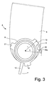
- the protruding element 14 of the locking wing 13 is slightly resilient, i.e. when influenced by a force (acting on the protruding element 14 and being directed axially towards the center of the connector element 8) it may flex to a certain degree with respect to the locking ring 9. Also, the radius from the centre of the connector element 8 to the outer edge of the locking wing 13, as indicated with r 1 in Fig. 3 , is slightly less than the distance from the centre of the connector element 8 to the outer edge of the tip 14a of the protruding element 14, as indicated with r 2 in Fig. 3 .
- the purpose of this design of the protruding element 14 is to allow locking of the locking ring 9 during a maneouvre in which the locking ring 9 is rotated - in a direction as indicated by means of an arrow in Fig. 3 - while forcing the tip 14a of the protruding element 14 to be forced to bend slightly inwards and then spring out towards an edge in the inlet connection 7 so as to be locked (to be described below).
- the locking ring 9 is also provided with a further protrusion 15, which extends between the locking ring 9 and a certain axial distance under the tip 14a of the protruding element 14. This is shown particularly clearly in Fig. 3 . Also, as shown in Figs. 2 and 3 , the protrusion 15 extends in the radial direction along a part of the locking ring 9.
- the protruding element 14 is formed with a relatively narrow first section 16 and a relatively wide second section 17, wherein the first section 16 is closest to the base part 13a of the locking wing 13 and wherein the second section 17 is closest to the tip 14a of the protruding element 14.
- the width of the first section 16 is slightly less than the width of the base part 13a of the locking wing 13.
- the second section 17 of the protruding element 14 is consideraby wider than the remaining parts of the protruding element 14. As will be described below, the second section 17 is used as a means to be pressed down by an operator so as to unlock the locking ring from a locked condition if this is desired.
- the locking ring 9 is also formed with an annular flange 18 which is positioned on the side of the locking ring 9 which faces the end portion of the connector element 8.
- the purpose of the flange 18 is to be inserted into a corresponding internal recess of a second annular ring 19.
- This second annular ring 19 is arranged between the locking ring 9 and an annular sealing ring 20, which is consequently also arranged on the end portion of the connector element 8.
- the second annular ring 19 and the sealing ring 20 constitutes a sealing which also absorbs slight differences in dimensions and tolerances between the various components.
- FIG. 4 A manouvre for mounting and locking the locking ring 9 to the inlet connection 7 of the turbo device 3 (see Fig. 1 ) will now be described with reference to Figs. 4 and 5 .
- the connector element 8 is positioned so that its end portion is aligned with a corresponding opening of the inlet connection 7.
- the inlet connection 7 is formed by a generally cylindrical and sleeve-shaped housing 21 which is wider than the end portion of the connector device 8 and which is formed with three guide sections 21 a, 21 b, 21 c, of which only the two first guide sections 21 a, 21 b are visible in Fig. 4 .
- the guide sections 21 a, 21 b are formed with a duct 22, 23, each having the function of a "guide passage" extending through the respective guide section 21 a, 21 b.
- a corresponding wing element 12, 13 may be inserted so as to pass through an associated duct 22, 23.
- a similar duct is formed in the third guide section 21 c although it is not visible in Fig. 4 .
- Fig. 4 describes an initial, unlocked position of the locking ring 9
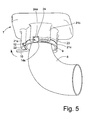
- Fig. 5 shows a locked position of the locking ring 9.
- each wing element is positioned just in front of a corresponding duct.
- the locking manoeuvre of the locking ring 9 can be said to be initiated when each wing element is guided through its corresponding duct while the locking ring 9 is forced to rotate in the direction as indicated by an arrow by pushing on the operating arm 10. This causes the wing elements 11, 12, 13 to be guided and inserted into the corresponding duct of each guide section 21 a, 21 b, 21 c.
- the guide sections 21 a, 21 b, 21 c are formed so that their ducts (of which the above-mentioned ducts 22 and 23 are shown clearly in Fig. 4 ) are generally of the same length as the length of the corresponding wing elements. This means that each one of the wing elements 11, 12, 13 may be fully inserted inside a corresponding duct during locking.
- the third wing element 13 with the protruding element 14 will be guided into the second guide section 21 b while the locking ring 9 is rotated as indicated above.
- the second guide section 21 b is both formed with a duct 23 which accommodates the third wing element 13, and is also formed with a cut-out section forming a recess 24.
- the protruding element 14 will be in a position at the left side (as seen in Fig. 4 ) of the corresponding guide section 21 b.
- the resilient protruding element 14 is configured so that its tip 14a extends further in a radial direction than the outer edge of the locking wing 13 (see also Fig. 3 ). This means that the protruding element 14 is bent slightly inwards during rotation of the locking ring 9, i.e. as the protruding element 14 is pressed through the corresponding duct 23 of the guide section 21 b. Finally, the protruding element 14 will click into place as shown in Fig. 5 due to the resiliency of the protruding element 14.
- the protruding element 14 comprises a first section 16 which connects to the locking wing 13 and which has a width which is less than the width of said locking wing 13. This means that the first section 16 and the second section 17 of the protruding element 14 will not be in contact with the inside of the duct 23 while the locking wing 13 is inserted into said duct 23 during locking of the locking ring 9. As a result, the protruding element 14 will generate a clear and loud "click" sound as the tip 14a of the protruding element 14 snaps into the recess 24 of the guide section 21 a.
- the protruding element 14 comprises an outer section 17 which extends in the axial direction of the connector element 8 and forms a "press tab", i.e. it serves as a means for unlocking said connector arrangement 6 when being pushed down.
- a "press tab” i.e. it serves as a means for unlocking said connector arrangement 6 when being pushed down.
- the locking ring 9 when the locking ring 9 is to be released, it is necessary to press down the outer section 17 of the protruding element 14 while rotating the locking ring 9 in a direction which is the opposite of the direction of the arrow in Figs. 4 and 5 .
- the locking ring 9 comprises a radially extending stop element 15 (see in particular Fig.
- this stop element 15 will define a limit for bending the protruding element 14 in the radial direction. This prevents the protruding element 14 from being pushed so hard that it may break during an unlocking maneouvre.
- Fig. 6 is a partly cross-sectional view of the locking ring 9 in its locked condition.
- the drawing shows the connector arrangement 6 with one of its wing elements 12 being inserted into a corresponding guide section 21 a. Also, the operating arm 10 of the locking ring 9 is shown.
- the locking ring 9 has an annular flange 18, which is positioned next to the second annular ring 19. Also, a sealing ring 20 is positioned next to the second annular ring 19 and forms a seal between the connector element 8 and the inlet connection 7.
- the embodiment described above is based on the fact that the locking ring 9 is freely rotatable around the end portion of the connector device 8.
- the locking ring may be fixed in relation to the connector device.
- Such an arrangement may be more easy and cost-effective to manufacture, but will also require that the entire connector device 8 is turned during the locking of the locking ring 9, which normally is possible depending on the space available in an engine arrangement.
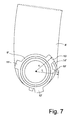
- a plane view of this embodiment is shown in Fig. 7 , which consequently shows a fixed locking ring 9' which is integrated with the connector element 8'.
- the fixed locking ring 9' comprises a first wing element 11', a second wing element 12' and a third wing element 13'.
- the third wing element 13' has the function of locking the locking ring 9' (and consequently also the connector element 8') to an inlet connection (not shown in Fig. 7 ) of an engine arrangement.
- the remaining parts of the embodiment shown in Fig. 7 i.e. the protruding element 14' and the second protrusion 15', correspond to those shown in Figs. 2 and 3 . For this reason, they are not described in further detail.
Landscapes
- Engineering & Computer Science (AREA)
- General Engineering & Computer Science (AREA)
- Mechanical Engineering (AREA)
- Chemical & Material Sciences (AREA)
- Combustion & Propulsion (AREA)
- Quick-Acting Or Multi-Walled Pipe Joints (AREA)
Description
- The invention relates to a connector arrangement comprising a tubular connector element configured for mounting on an inlet of a further component and an annular locking ring arranged around an end section of the connector element.
- The invention can be used in different types of arrangements of conduits or tubular connections in which there is a need for connecting a tubular connector element to a further component. For example, the invention can be used in an engine compartment of a vehicle, for connecting various conduits between components in said engine compartment.
- In the automotive industry, in particular in the field of manufacturing of vehicles, there is a constant need for simple, quick and cost-effective methods and arrangements for assembly of vehicles and vehicle parts.
- For example, with regard to an engine arrangement in a vehicle, there is often a complex arrangement of conduits and tubular elements between various components of the engine arrangement, such as inlets and outlets of a compressor, a turbo device, a catalytic converter or other parts of the engine arrangement.
- It is a general requirement that tubular conduits and connections for such conduits should be of high quality and also be quick and easy to mount, i.e. during the actual assembly of the engine arrangement or the entire vehicle. An example of such connections is the inlet and outlet conduits of a turbo device.
- To solve the above-mentioned requirements, it is today known to provide connecting arrangements with tubular end sections which can be fastened by screw connections and similar so as to provide a secure connection of said connecting arrangement. Also, there exist solutions which include bayonet-type fastening devices for mounting of inlet tubes for turbo devices and similar components.
- However, there is a constant need for improved connector devices which are reliable and functionally secure and which also provides a possibility for easy manufacturing and easy assembly. This may lead to advantages in the form of a more cost-effective manufacturing process of vehicles.
- Consequently, an object of the invention is to provide a connector arrangement which allows an improved mounting procedure as compared with the above-mentioned prior art solutions while providing a secure connection.
- The above-mentioned object is achieved by a connector arrangement comprising a tubular connector element configured for mounting on an inlet of a further component and an annular locking ring arranged around an end section of the connector element. The locking ring comprises at least two wing elements extending in a radial direction and configured for being inserted into corresponding guide sections in said inlet, and in that at least one of said wing elements constitutes a locking wing with a resilient protrusion extending along the periphery of the locking ring and cooperating with a locking recess in a corresponding guide section upon rotating said locking ring in relation to said inlet.
- The invention provides certain advantages over previously known technology, primarily due to the fact that it leads to a quick and easy mounting procedure which in turn simplifies the assembly of the engine arrangement.
- According to an embodiment, the resilient protrusion is configured so that its tip extends further in a radial direction than said locking wing. In this manner, the resilient protrusion may be bent and then snap back during locking of the locking wing. Preferably, the locking recess has a radially extending end wall which serves to lock the protruding element.
- Furthermore, according to an embodiment, the protruding element comprises a first section which connects to the locking wing and has a width which is less than the width of said locking wing. In this manner, the protruding element will generate a loud "click" when it is locked. This clearly audible "click" sound will serve as an acknowledgement for the person who is locking the connector device that the locking ring is locked.
- Futhermore, according to an embodiment, the protruding element comprises a section extending in the axial direction of the connector element and serving as a means for unlocking said connector arrangement when being pushed.
- Preferably, the locking ring also comprises a radially extending stop element between the protruding element and the locking ring and constituting a limit for flexing said protruding element in the radial direction. This prevents the protruding element from being broken during unlocking.
- According to an embodiment, the locking ring is freely rotatable around the connector element. According to a further embodiment, the locking ring is fixedly mounted on said connector element.
- The invention can be applied in different types of vehicles, such as cars, trucks, and buses. Although the invention will be described with respect to an application in the form of a conventional engine arrangement, the invention is not restricted to such arrangement only but can generally be used in any type of arrangement involving tubular connector elements which should be locked to each other.
- Further advantages and advantageous features of the invention are disclosed in the following description and in the dependent claims.
- Further objects, features, and advantages of the present disclosure will appear from the following detailed description, wherein certain aspects of the disclosure will be described in more detail with reference to the accompanying drawings, in which:
- Fig. 1
- shows in a schematical manner an engine arrangement for a vehicle;
- Fig. 2
- is a perspective view of a connector arrangement according to an embodiment of the invention;
- Fig. 3
- is a plane view as seen towards an end of the connector arrangement;
- Fig. 4
- is a perspective view of the embodiment in a first operating condition during locking of a connector element to a further component;
- Fig. 5
- is a perspective view of the embodiment in a second operating condition in which the connector element is locked to said further component;
- Fig. 6
- is a cross-sectional view of the embodiment, in its locked condition; and
- Fig. 7
- is a plane view of a second embodiment of the invention.
- Different embodiments of the present invention will be described with reference to the accompanying drawings. The arrangements described below can be realized in many different forms and should not be construed as being limited to the embodiments described below.
- With initial reference to
Fig. 1 , there is shown a simplified side view of anengine arrangement 1 in a vehicle. Theengine arrangement 1 comprises aninternal combustion engine 2 with a conventional turbo device 3 and an associatedinlet conduit 4 andoutlet conduit 5 of theturbo device 4. Theinlet conduit 4 is connected to the turbo device 3 by means of aconnector arrangement 6, which extends to the turbo device 3 and can be connected to said turbo device 3 via aninlet connection 7. Theconnector arrangement 6 and theinlet connection 7 are shown in a simplified manner inFig. 1 and will consequently be described in greater detail below. - With reference now to both
Figs. 2 and3 , it can be noted that theconnector arrangement 6 comprises aconnector element 8 which is generally tubular and which has an end section which supports a generallyannular locking ring 9 which is arranged around saidconnector element 8. According to this first embodiment of the invention, thelocking ring 9 is arranged so that it can be freely rotated on theconnector element 8, i.e. it is not fixed on the end section of theconnector element 8. Furthermore, thelocking ring 9 supports anoperating arm 10 by means of which thelocking ring 9 can be manually forced to rotate around theconnector element 8 during a locking maneouvre, as will be described in detail below. Theoperating arm 10 is also visible inFig. 1 . - According to the embodiment, the
locking ring 9 is formed with threewing elements locking ring 9. It should be noted that thefirst wing element 11 is not visible inFig. 2 . Thewing elements locking ring 9. Twowing elements locking ring 9, whereas thethird wing element 13 has the same shape as the first twowing elements protruding element 14 which extends along a part of the circumference of thelocking ring 9. As will be described below, thisthird wing element 13 has a function of locking thelocking ring 9 to theinlet connection 7 of the turbo device 3. For this reason, this element is also referred to as alocking wing 13. - The protruding
element 14 of the lockingwing 13 is slightly resilient, i.e. when influenced by a force (acting on the protrudingelement 14 and being directed axially towards the center of the connector element 8) it may flex to a certain degree with respect to thelocking ring 9. Also, the radius from the centre of theconnector element 8 to the outer edge of the lockingwing 13, as indicated with r1 inFig. 3 , is slightly less than the distance from the centre of theconnector element 8 to the outer edge of thetip 14a of the protrudingelement 14, as indicated with r2 inFig. 3 . The purpose of this design of the protrudingelement 14 is to allow locking of thelocking ring 9 during a maneouvre in which thelocking ring 9 is rotated - in a direction as indicated by means of an arrow inFig. 3 - while forcing thetip 14a of the protrudingelement 14 to be forced to bend slightly inwards and then spring out towards an edge in theinlet connection 7 so as to be locked (to be described below). - The
locking ring 9 is also provided with afurther protrusion 15, which extends between the lockingring 9 and a certain axial distance under thetip 14a of the protrudingelement 14. This is shown particularly clearly inFig. 3 . Also, as shown inFigs. 2 and3 , theprotrusion 15 extends in the radial direction along a part of thelocking ring 9. - With particular reference to
Fig. 2 , it is noted that the protrudingelement 14 is formed with a relatively narrowfirst section 16 and a relatively widesecond section 17, wherein thefirst section 16 is closest to thebase part 13a of the lockingwing 13 and wherein thesecond section 17 is closest to thetip 14a of the protrudingelement 14. In this regard, it should be noted that the width of thefirst section 16 is slightly less than the width of thebase part 13a of the lockingwing 13. - Also, the
second section 17 of the protrudingelement 14 is consideraby wider than the remaining parts of the protrudingelement 14. As will be described below, thesecond section 17 is used as a means to be pressed down by an operator so as to unlock the locking ring from a locked condition if this is desired. - As shown in
Fig. 2 , thelocking ring 9 is also formed with anannular flange 18 which is positioned on the side of thelocking ring 9 which faces the end portion of theconnector element 8. The purpose of theflange 18 is to be inserted into a corresponding internal recess of a secondannular ring 19. This secondannular ring 19 is arranged between the lockingring 9 and anannular sealing ring 20, which is consequently also arranged on the end portion of theconnector element 8. The secondannular ring 19 and the sealingring 20 constitutes a sealing which also absorbs slight differences in dimensions and tolerances between the various components. - A manouvre for mounting and locking the
locking ring 9 to theinlet connection 7 of the turbo device 3 (seeFig. 1 ) will now be described with reference toFigs. 4 and5 . Initially, with reference toFig. 4 , it is noted that theconnector element 8 is positioned so that its end portion is aligned with a corresponding opening of theinlet connection 7. Theinlet connection 7 is formed by a generally cylindrical and sleeve-shapedhousing 21 which is wider than the end portion of theconnector device 8 and which is formed with threeguide sections first guide sections Fig. 4 . - As shown in
Fig. 4 , theguide sections duct respective guide section corresponding wing element duct third guide section 21 c although it is not visible inFig. 4 . - Furthermore,
Fig. 4 describes an initial, unlocked position of thelocking ring 9 andFig. 5 shows a locked position of thelocking ring 9. In the unlocked position of thelocking ring 9, each wing element is positioned just in front of a corresponding duct. Furthermore, the locking manoeuvre of thelocking ring 9 can be said to be initiated when each wing element is guided through its corresponding duct while thelocking ring 9 is forced to rotate in the direction as indicated by an arrow by pushing on theoperating arm 10. This causes thewing elements guide section - As the
locking ring 9 is rotated, all thewing elements guide sections inlet component 7. Furthermore, theguide sections ducts Fig. 4 ) are generally of the same length as the length of the corresponding wing elements. This means that each one of thewing elements - During the locking maneouvre, the
third wing element 13 with the protrudingelement 14 will be guided into thesecond guide section 21 b while thelocking ring 9 is rotated as indicated above. Here, it should be noted that thesecond guide section 21 b is both formed with aduct 23 which accommodates thethird wing element 13, and is also formed with a cut-out section forming arecess 24. When thethird wing element 13 has been rotated to be positioned under therecess 24, the protrudingelement 14 will be in a position at the left side (as seen inFig. 4 ) of thecorresponding guide section 21 b. - Now, as the
locking ring 9 is further rotated in the direction of the arrow inFig. 4 , theguide section 21 b will act on the protrudingelement 14 so that it will be slightly bent downwards (i.e. towards the locking ring 9) through its resiliency. When thetip 14a of the protrudingelement 14 finally reaches a position which is aligned with therecess 24, thetip 14a of the protrudingelement 14 will flex back and snap in a radial direction into therecess 24. This position is shown inFig. 5 . This means that thetip 14a now bears against arear wall 24a of therecess 24 and cannot be rotated in the reverse direction. In other words, thelocking ring 9 is now locked and cannot be rotated. Consequently, theentire connector device 8 is now locked to theinlet connection 7. - As mentioned above, and with reference to
Fig. 5 , it should be noted that the resilient protrudingelement 14 is configured so that itstip 14a extends further in a radial direction than the outer edge of the locking wing 13 (see alsoFig. 3 ). This means that the protrudingelement 14 is bent slightly inwards during rotation of thelocking ring 9, i.e. as the protrudingelement 14 is pressed through the correspondingduct 23 of theguide section 21 b. Finally, the protrudingelement 14 will click into place as shown inFig. 5 due to the resiliency of the protrudingelement 14. - Also, as shown in
Fig. 2 , the protrudingelement 14 comprises afirst section 16 which connects to the lockingwing 13 and which has a width which is less than the width of said lockingwing 13. This means that thefirst section 16 and thesecond section 17 of the protrudingelement 14 will not be in contact with the inside of theduct 23 while the lockingwing 13 is inserted into saidduct 23 during locking of thelocking ring 9. As a result, the protrudingelement 14 will generate a clear and loud "click" sound as thetip 14a of the protrudingelement 14 snaps into therecess 24 of theguide section 21 a. This is an advantage during assembly of the engine arrangement, since the person who is mounting theconnector arrangement 6 will know for certain that theconnector device 8 has been locked into place when the "click" sound is generated. A further advantage of this arrangement is that less friction is generated when the lockingwing 13 is pressed through its correspondingduct 23. - Furthermore, the protruding
element 14 comprises anouter section 17 which extends in the axial direction of theconnector element 8 and forms a "press tab", i.e. it serves as a means for unlocking saidconnector arrangement 6 when being pushed down. In other words, when thelocking ring 9 is to be released, it is necessary to press down theouter section 17 of the protrudingelement 14 while rotating thelocking ring 9 in a direction which is the opposite of the direction of the arrow inFigs. 4 and5 . Also, due to the fact that thelocking ring 9 comprises a radially extending stop element 15 (see in particularFig. 3 ) which is positioned radially under the protrudingelement 14, thisstop element 15 will define a limit for bending the protrudingelement 14 in the radial direction. This prevents the protrudingelement 14 from being pushed so hard that it may break during an unlocking maneouvre. -
Fig. 6 is a partly cross-sectional view of thelocking ring 9 in its locked condition. The drawing shows theconnector arrangement 6 with one of itswing elements 12 being inserted into acorresponding guide section 21 a. Also, theoperating arm 10 of thelocking ring 9 is shown. - As explained above with reference to
Fig. 2 , thelocking ring 9 has anannular flange 18, which is positioned next to the secondannular ring 19. Also, a sealingring 20 is positioned next to the secondannular ring 19 and forms a seal between theconnector element 8 and theinlet connection 7. - The embodiment described above is based on the fact that the
locking ring 9 is freely rotatable around the end portion of theconnector device 8. According to an alternative embodiment, the locking ring may be fixed in relation to the connector device. Such an arrangement may be more easy and cost-effective to manufacture, but will also require that theentire connector device 8 is turned during the locking of thelocking ring 9, which normally is possible depending on the space available in an engine arrangement. A plane view of this embodiment is shown inFig. 7 , which consequently shows a fixed locking ring 9' which is integrated with the connector element 8'. In a manner which is similar to the embodiment shown inFig. 3 , the fixed locking ring 9' comprises a first wing element 11', a second wing element 12' and a third wing element 13'. The third wing element 13' has the function of locking the locking ring 9' (and consequently also the connector element 8') to an inlet connection (not shown inFig. 7 ) of an engine arrangement. The remaining parts of the embodiment shown inFig. 7 , i.e. the protruding element 14' and the second protrusion 15', correspond to those shown inFigs. 2 and3 . For this reason, they are not described in further detail. - It is to be understood that the present invention is not limited to the embodiments described above and illustrated in the drawings. The skilled person will recognize that changes and modifications may be made within the scope of the appended claims.
Claims (9)
- Connector arrangement (6) comprising a tubular connector element (8; 8') configured for mounting on an inlet (7) of a further component (3) and an annular locking ring (9; 9') arranged around an end section of the connector element (8; 8'), characterized in that said locking ring (9; 9') comprises at least two wing elements (11; 11', 12; 12', 13; 13') extending in a radial direction and configured for being inserted into corresponding guide sections (21 a, 21 b, 21 c) in said inlet (7), and in that at least one of said wing elements (13; 13') constitutes a locking wing (13; 13') with a resilient protrusion (14; 14') extending along the periphery of the locking ring (9; 9') and cooperating with a locking recess (24) in a corresponding guide section (21 b) upon rotating said locking ring (9; 9') in relation to said inlet (7).
- Connector arrangement (6) according to claim 1, wherein said resilient protrusion (14; 14') is configured so that its tip (14a) extends further in a radial direction than said locking wing (13; 13').
- Connector arrangement (6) according to claim 1 or 2, wherein said locking recess (24) comprises a radially extending end wall (24a) serving as a locking wall for the protruding element (14; 14') in its locked condition.
- Connector arrangement (6) according to any one of the preceding claims, wherein the protruding element (14; 14') comprises a first section (16) which connects to the locking wing (13; 13') and which has a width which is less than the width of said locking wing (13; 13').
- Connector arrangement (6) according to any one of the preceding claims, wherein the protruding element (14; 14') comprises a section (17) which extends in the axial direction of the connector element (8') and which serves as a means for unlocking said connector arrangement (6) when being pushed.
- Connector arrangement (6) according to any one of the preceding claims, wherein the locking ring (9; 9') further comprises a radially extending stop element (15; 15') positioned radially between the protruding element (14; 14') and the locking ring (9; 9') and constituting a limit for flexing said protruding element (14; 14') in the radial direction.
- Connector arrangement (6) according to any one of the preceding claims, wherein the locking ring (9) is freely rotatable around the connector element (8).
- Connector arrangement (6) according to any one of the preceding claims, wherein the locking ring (9) supports an operating arm (10) being configured for manually rotating said locking ring (9)
- Connector arrangement (6) according to any one of claims 1-6, wherein said locking ring (9') is fixedly mounted on said connector element (8').
Priority Applications (1)
| Application Number | Priority Date | Filing Date | Title |
|---|---|---|---|
| EP14182078.7A EP2990635B1 (en) | 2014-08-25 | 2014-08-25 | Connector arrangement |
Applications Claiming Priority (1)
| Application Number | Priority Date | Filing Date | Title |
|---|---|---|---|
| EP14182078.7A EP2990635B1 (en) | 2014-08-25 | 2014-08-25 | Connector arrangement |
Publications (2)
| Publication Number | Publication Date |
|---|---|
| EP2990635A1 true EP2990635A1 (en) | 2016-03-02 |
| EP2990635B1 EP2990635B1 (en) | 2017-06-28 |
Family
ID=51392119
Family Applications (1)
| Application Number | Title | Priority Date | Filing Date |
|---|---|---|---|
| EP14182078.7A Active EP2990635B1 (en) | 2014-08-25 | 2014-08-25 | Connector arrangement |
Country Status (1)
| Country | Link |
|---|---|
| EP (1) | EP2990635B1 (en) |
Cited By (2)
| Publication number | Priority date | Publication date | Assignee | Title |
|---|---|---|---|---|
| CN114901982A (en) * | 2020-02-28 | 2022-08-12 | 德国诺玛公司 | Device and set of devices for coding a first and a second connection partner of a bayonet lock |
| DE102024132400A1 (en) * | 2024-11-06 | 2026-05-21 | Norma Germany Gmbh | quick connectors |
Citations (4)
| Publication number | Priority date | Publication date | Assignee | Title |
|---|---|---|---|---|
| US2851288A (en) * | 1956-09-04 | 1958-09-09 | William Wallace Company | Telescopic wall flue connection with locking ring |
| WO1985005667A1 (en) * | 1984-06-01 | 1985-12-19 | O.E.M. Technical Sales, Incorporated | Flexible joint for pipes |
| DE19637055A1 (en) * | 1996-09-12 | 1998-03-19 | Bosch Gmbh Robert | Valve for an internal combustion engine and internal combustion engine |
| WO2002101884A1 (en) * | 2001-05-18 | 2002-12-19 | Pc Electric Ges.M.B.H. | Electric plug-type connector |
Family Cites Families (1)
| Publication number | Priority date | Publication date | Assignee | Title |
|---|---|---|---|---|
| JP5914766B2 (en) * | 2012-10-10 | 2016-05-11 | マーレ インターナショナル ゲゼルシャフト ミット ベシュレンクテル ハフツングMAHLE International GmbH | Connecting device for intake system |
-
2014
- 2014-08-25 EP EP14182078.7A patent/EP2990635B1/en active Active
Patent Citations (4)
| Publication number | Priority date | Publication date | Assignee | Title |
|---|---|---|---|---|
| US2851288A (en) * | 1956-09-04 | 1958-09-09 | William Wallace Company | Telescopic wall flue connection with locking ring |
| WO1985005667A1 (en) * | 1984-06-01 | 1985-12-19 | O.E.M. Technical Sales, Incorporated | Flexible joint for pipes |
| DE19637055A1 (en) * | 1996-09-12 | 1998-03-19 | Bosch Gmbh Robert | Valve for an internal combustion engine and internal combustion engine |
| WO2002101884A1 (en) * | 2001-05-18 | 2002-12-19 | Pc Electric Ges.M.B.H. | Electric plug-type connector |
Cited By (2)
| Publication number | Priority date | Publication date | Assignee | Title |
|---|---|---|---|---|
| CN114901982A (en) * | 2020-02-28 | 2022-08-12 | 德国诺玛公司 | Device and set of devices for coding a first and a second connection partner of a bayonet lock |
| DE102024132400A1 (en) * | 2024-11-06 | 2026-05-21 | Norma Germany Gmbh | quick connectors |
Also Published As
| Publication number | Publication date |
|---|---|
| EP2990635B1 (en) | 2017-06-28 |
Similar Documents
| Publication | Publication Date | Title |
|---|---|---|
| EP1705417B1 (en) | Quick connector for pipes | |
| US5724946A (en) | Fuel rail and injector assembly | |
| US20190136894A1 (en) | Connector with enhanced mounting process | |
| CN112751296B (en) | Wire sheath | |
| US11959574B2 (en) | Fluid connection device | |
| CN110884445B (en) | Guard ring | |
| US11940298B2 (en) | Magnet assembly for a sensor device of a motor vehicle, sensor device with a magnet assembly and motor vehicle with a sensor device | |
| US20170009637A1 (en) | Tailpipe Cover for an Exhaust System of a Motor Vehicle and Exhaust System Having Such a Tailpipe Cover | |
| CN112744167A (en) | Wire sheath | |
| JP6486631B2 (en) | Refueling system and assembly method thereof | |
| US20170234469A1 (en) | Push-in connector | |
| EP2990635B1 (en) | Connector arrangement | |
| CN110226060B (en) | Hole plug | |
| US20160123511A1 (en) | Duct assembly with a connector | |
| CN111512030B (en) | Device and method for connecting fluid-conducting components | |
| CN112751295B (en) | Wire sheath | |
| US11906004B2 (en) | Freewheel assembly having a deep-drawn flange | |
| US20230178271A1 (en) | Grommet and wire harness | |
| CN115485944A (en) | Wire harness fixing member and wire harness | |
| JP2022186441A (en) | Grommet | |
| WO2022181362A1 (en) | Grommet | |
| JP5765101B2 (en) | Grommet | |
| US11739794B2 (en) | Clamp yoke error proofing device and method | |
| KR101478923B1 (en) | Quick Connector | |
| US10461603B2 (en) | Fan motor support |
Legal Events
| Date | Code | Title | Description |
|---|---|---|---|
| PUAI | Public reference made under article 153(3) epc to a published international application that has entered the european phase |
Free format text: ORIGINAL CODE: 0009012 |
|
| AK | Designated contracting states |
Kind code of ref document: A1 Designated state(s): AL AT BE BG CH CY CZ DE DK EE ES FI FR GB GR HR HU IE IS IT LI LT LU LV MC MK MT NL NO PL PT RO RS SE SI SK SM TR |
|
| AX | Request for extension of the european patent |
Extension state: BA ME |
|
| 17P | Request for examination filed |
Effective date: 20160902 |
|
| RBV | Designated contracting states (corrected) |
Designated state(s): AL AT BE BG CH CY CZ DE DK EE ES FI FR GB GR HR HU IE IS IT LI LT LU LV MC MK MT NL NO PL PT RO RS SE SI SK SM TR |
|
| GRAP | Despatch of communication of intention to grant a patent |
Free format text: ORIGINAL CODE: EPIDOSNIGR1 |
|
| INTG | Intention to grant announced |
Effective date: 20170216 |
|
| GRAS | Grant fee paid |
Free format text: ORIGINAL CODE: EPIDOSNIGR3 |
|
| GRAA | (expected) grant |
Free format text: ORIGINAL CODE: 0009210 |
|
| AK | Designated contracting states |
Kind code of ref document: B1 Designated state(s): AL AT BE BG CH CY CZ DE DK EE ES FI FR GB GR HR HU IE IS IT LI LT LU LV MC MK MT NL NO PL PT RO RS SE SI SK SM TR |
|
| REG | Reference to a national code |
Ref country code: GB Ref legal event code: FG4D |
|
| REG | Reference to a national code |
Ref country code: CH Ref legal event code: EP |
|
| REG | Reference to a national code |
Ref country code: AT Ref legal event code: REF Ref document number: 905076 Country of ref document: AT Kind code of ref document: T Effective date: 20170715 |
|
| REG | Reference to a national code |
Ref country code: IE Ref legal event code: FG4D |
|
| REG | Reference to a national code |
Ref country code: DE Ref legal event code: R096 Ref document number: 602014011156 Country of ref document: DE |
|
| REG | Reference to a national code |
Ref country code: SE Ref legal event code: TRGR |
|
| PG25 | Lapsed in a contracting state [announced via postgrant information from national office to epo] |
Ref country code: HR Free format text: LAPSE BECAUSE OF FAILURE TO SUBMIT A TRANSLATION OF THE DESCRIPTION OR TO PAY THE FEE WITHIN THE PRESCRIBED TIME-LIMIT Effective date: 20170628 Ref country code: FI Free format text: LAPSE BECAUSE OF FAILURE TO SUBMIT A TRANSLATION OF THE DESCRIPTION OR TO PAY THE FEE WITHIN THE PRESCRIBED TIME-LIMIT Effective date: 20170628 Ref country code: LT Free format text: LAPSE BECAUSE OF FAILURE TO SUBMIT A TRANSLATION OF THE DESCRIPTION OR TO PAY THE FEE WITHIN THE PRESCRIBED TIME-LIMIT Effective date: 20170628 Ref country code: GR Free format text: LAPSE BECAUSE OF FAILURE TO SUBMIT A TRANSLATION OF THE DESCRIPTION OR TO PAY THE FEE WITHIN THE PRESCRIBED TIME-LIMIT Effective date: 20170929 Ref country code: NO Free format text: LAPSE BECAUSE OF FAILURE TO SUBMIT A TRANSLATION OF THE DESCRIPTION OR TO PAY THE FEE WITHIN THE PRESCRIBED TIME-LIMIT Effective date: 20170928 |
|
| REG | Reference to a national code |
Ref country code: NL Ref legal event code: MP Effective date: 20170628 |
|
| REG | Reference to a national code |
Ref country code: LT Ref legal event code: MG4D |
|
| REG | Reference to a national code |
Ref country code: AT Ref legal event code: MK05 Ref document number: 905076 Country of ref document: AT Kind code of ref document: T Effective date: 20170628 |
|
| PG25 | Lapsed in a contracting state [announced via postgrant information from national office to epo] |
Ref country code: RS Free format text: LAPSE BECAUSE OF FAILURE TO SUBMIT A TRANSLATION OF THE DESCRIPTION OR TO PAY THE FEE WITHIN THE PRESCRIBED TIME-LIMIT Effective date: 20170628 Ref country code: NL Free format text: LAPSE BECAUSE OF FAILURE TO SUBMIT A TRANSLATION OF THE DESCRIPTION OR TO PAY THE FEE WITHIN THE PRESCRIBED TIME-LIMIT Effective date: 20170628 Ref country code: BG Free format text: LAPSE BECAUSE OF FAILURE TO SUBMIT A TRANSLATION OF THE DESCRIPTION OR TO PAY THE FEE WITHIN THE PRESCRIBED TIME-LIMIT Effective date: 20170928 Ref country code: LV Free format text: LAPSE BECAUSE OF FAILURE TO SUBMIT A TRANSLATION OF THE DESCRIPTION OR TO PAY THE FEE WITHIN THE PRESCRIBED TIME-LIMIT Effective date: 20170628 |
|
| PG25 | Lapsed in a contracting state [announced via postgrant information from national office to epo] |
Ref country code: AT Free format text: LAPSE BECAUSE OF FAILURE TO SUBMIT A TRANSLATION OF THE DESCRIPTION OR TO PAY THE FEE WITHIN THE PRESCRIBED TIME-LIMIT Effective date: 20170628 Ref country code: RO Free format text: LAPSE BECAUSE OF FAILURE TO SUBMIT A TRANSLATION OF THE DESCRIPTION OR TO PAY THE FEE WITHIN THE PRESCRIBED TIME-LIMIT Effective date: 20170628 Ref country code: EE Free format text: LAPSE BECAUSE OF FAILURE TO SUBMIT A TRANSLATION OF THE DESCRIPTION OR TO PAY THE FEE WITHIN THE PRESCRIBED TIME-LIMIT Effective date: 20170628 Ref country code: CZ Free format text: LAPSE BECAUSE OF FAILURE TO SUBMIT A TRANSLATION OF THE DESCRIPTION OR TO PAY THE FEE WITHIN THE PRESCRIBED TIME-LIMIT Effective date: 20170628 Ref country code: SK Free format text: LAPSE BECAUSE OF FAILURE TO SUBMIT A TRANSLATION OF THE DESCRIPTION OR TO PAY THE FEE WITHIN THE PRESCRIBED TIME-LIMIT Effective date: 20170628 |
|
| PG25 | Lapsed in a contracting state [announced via postgrant information from national office to epo] |
Ref country code: ES Free format text: LAPSE BECAUSE OF FAILURE TO SUBMIT A TRANSLATION OF THE DESCRIPTION OR TO PAY THE FEE WITHIN THE PRESCRIBED TIME-LIMIT Effective date: 20170628 Ref country code: IT Free format text: LAPSE BECAUSE OF FAILURE TO SUBMIT A TRANSLATION OF THE DESCRIPTION OR TO PAY THE FEE WITHIN THE PRESCRIBED TIME-LIMIT Effective date: 20170628 Ref country code: IS Free format text: LAPSE BECAUSE OF FAILURE TO SUBMIT A TRANSLATION OF THE DESCRIPTION OR TO PAY THE FEE WITHIN THE PRESCRIBED TIME-LIMIT Effective date: 20171028 Ref country code: SM Free format text: LAPSE BECAUSE OF FAILURE TO SUBMIT A TRANSLATION OF THE DESCRIPTION OR TO PAY THE FEE WITHIN THE PRESCRIBED TIME-LIMIT Effective date: 20170628 Ref country code: PL Free format text: LAPSE BECAUSE OF FAILURE TO SUBMIT A TRANSLATION OF THE DESCRIPTION OR TO PAY THE FEE WITHIN THE PRESCRIBED TIME-LIMIT Effective date: 20170628 |
|
| REG | Reference to a national code |
Ref country code: CH Ref legal event code: PL Ref country code: DE Ref legal event code: R097 Ref document number: 602014011156 Country of ref document: DE |
|
| PG25 | Lapsed in a contracting state [announced via postgrant information from national office to epo] |
Ref country code: MC Free format text: LAPSE BECAUSE OF FAILURE TO SUBMIT A TRANSLATION OF THE DESCRIPTION OR TO PAY THE FEE WITHIN THE PRESCRIBED TIME-LIMIT Effective date: 20170628 |
|
| PG25 | Lapsed in a contracting state [announced via postgrant information from national office to epo] |
Ref country code: CH Free format text: LAPSE BECAUSE OF NON-PAYMENT OF DUE FEES Effective date: 20170831 Ref country code: LI Free format text: LAPSE BECAUSE OF NON-PAYMENT OF DUE FEES Effective date: 20170831 Ref country code: DK Free format text: LAPSE BECAUSE OF FAILURE TO SUBMIT A TRANSLATION OF THE DESCRIPTION OR TO PAY THE FEE WITHIN THE PRESCRIBED TIME-LIMIT Effective date: 20170628 |
|
| PLBE | No opposition filed within time limit |
Free format text: ORIGINAL CODE: 0009261 |
|
| STAA | Information on the status of an ep patent application or granted ep patent |
Free format text: STATUS: NO OPPOSITION FILED WITHIN TIME LIMIT |
|
| REG | Reference to a national code |
Ref country code: FR Ref legal event code: ST Effective date: 20180430 |
|
| REG | Reference to a national code |
Ref country code: IE Ref legal event code: MM4A |
|
| 26N | No opposition filed |
Effective date: 20180329 |
|
| REG | Reference to a national code |
Ref country code: BE Ref legal event code: MM Effective date: 20170831 |
|
| PG25 | Lapsed in a contracting state [announced via postgrant information from national office to epo] |
Ref country code: LU Free format text: LAPSE BECAUSE OF NON-PAYMENT OF DUE FEES Effective date: 20170825 |
|
| PG25 | Lapsed in a contracting state [announced via postgrant information from national office to epo] |
Ref country code: IE Free format text: LAPSE BECAUSE OF NON-PAYMENT OF DUE FEES Effective date: 20170825 |
|
| PG25 | Lapsed in a contracting state [announced via postgrant information from national office to epo] |
Ref country code: FR Free format text: LAPSE BECAUSE OF NON-PAYMENT OF DUE FEES Effective date: 20170831 Ref country code: BE Free format text: LAPSE BECAUSE OF NON-PAYMENT OF DUE FEES Effective date: 20170831 Ref country code: SI Free format text: LAPSE BECAUSE OF FAILURE TO SUBMIT A TRANSLATION OF THE DESCRIPTION OR TO PAY THE FEE WITHIN THE PRESCRIBED TIME-LIMIT Effective date: 20170628 |
|
| PG25 | Lapsed in a contracting state [announced via postgrant information from national office to epo] |
Ref country code: MT Free format text: LAPSE BECAUSE OF NON-PAYMENT OF DUE FEES Effective date: 20170825 |
|
| PGFP | Annual fee paid to national office [announced via postgrant information from national office to epo] |
Ref country code: SE Payment date: 20180822 Year of fee payment: 5 Ref country code: GB Payment date: 20180813 Year of fee payment: 5 |
|
| PG25 | Lapsed in a contracting state [announced via postgrant information from national office to epo] |
Ref country code: HU Free format text: LAPSE BECAUSE OF FAILURE TO SUBMIT A TRANSLATION OF THE DESCRIPTION OR TO PAY THE FEE WITHIN THE PRESCRIBED TIME-LIMIT; INVALID AB INITIO Effective date: 20140825 |
|
| PG25 | Lapsed in a contracting state [announced via postgrant information from national office to epo] |
Ref country code: CY Free format text: LAPSE BECAUSE OF FAILURE TO SUBMIT A TRANSLATION OF THE DESCRIPTION OR TO PAY THE FEE WITHIN THE PRESCRIBED TIME-LIMIT Effective date: 20170628 |
|
| PG25 | Lapsed in a contracting state [announced via postgrant information from national office to epo] |
Ref country code: MK Free format text: LAPSE BECAUSE OF FAILURE TO SUBMIT A TRANSLATION OF THE DESCRIPTION OR TO PAY THE FEE WITHIN THE PRESCRIBED TIME-LIMIT Effective date: 20170628 |
|
| PG25 | Lapsed in a contracting state [announced via postgrant information from national office to epo] |
Ref country code: TR Free format text: LAPSE BECAUSE OF FAILURE TO SUBMIT A TRANSLATION OF THE DESCRIPTION OR TO PAY THE FEE WITHIN THE PRESCRIBED TIME-LIMIT Effective date: 20170628 |
|
| REG | Reference to a national code |
Ref country code: SE Ref legal event code: EUG |
|
| GBPC | Gb: european patent ceased through non-payment of renewal fee |
Effective date: 20190825 |
|
| PG25 | Lapsed in a contracting state [announced via postgrant information from national office to epo] |
Ref country code: SE Free format text: LAPSE BECAUSE OF NON-PAYMENT OF DUE FEES Effective date: 20190826 |
|
| PG25 | Lapsed in a contracting state [announced via postgrant information from national office to epo] |
Ref country code: PT Free format text: LAPSE BECAUSE OF FAILURE TO SUBMIT A TRANSLATION OF THE DESCRIPTION OR TO PAY THE FEE WITHIN THE PRESCRIBED TIME-LIMIT Effective date: 20170628 |
|
| PG25 | Lapsed in a contracting state [announced via postgrant information from national office to epo] |
Ref country code: AL Free format text: LAPSE BECAUSE OF FAILURE TO SUBMIT A TRANSLATION OF THE DESCRIPTION OR TO PAY THE FEE WITHIN THE PRESCRIBED TIME-LIMIT Effective date: 20170628 |
|
| PG25 | Lapsed in a contracting state [announced via postgrant information from national office to epo] |
Ref country code: GB Free format text: LAPSE BECAUSE OF NON-PAYMENT OF DUE FEES Effective date: 20190825 |
|
| P01 | Opt-out of the competence of the unified patent court (upc) registered |
Effective date: 20231212 |
|
| PGFP | Annual fee paid to national office [announced via postgrant information from national office to epo] |
Ref country code: DE Payment date: 20250724 Year of fee payment: 12 |