EP2990542A2 - Hybrid construction machine - Google Patents
Hybrid construction machine Download PDFInfo
- Publication number
- EP2990542A2 EP2990542A2 EP15181547.9A EP15181547A EP2990542A2 EP 2990542 A2 EP2990542 A2 EP 2990542A2 EP 15181547 A EP15181547 A EP 15181547A EP 2990542 A2 EP2990542 A2 EP 2990542A2
- Authority
- EP
- European Patent Office
- Prior art keywords
- voltage
- difference voltage
- storage device
- power storage
- battery
- Prior art date
- Legal status (The legal status is an assumption and is not a legal conclusion. Google has not performed a legal analysis and makes no representation as to the accuracy of the status listed.)
- Granted
Links
Images


Classifications
-
- E—FIXED CONSTRUCTIONS
- E02—HYDRAULIC ENGINEERING; FOUNDATIONS; SOIL SHIFTING
- E02F—DREDGING; SOIL-SHIFTING
- E02F9/00—Component parts of dredgers or soil-shifting machines, not restricted to one of the kinds covered by groups E02F3/00 - E02F7/00
- E02F9/20—Drives; Control devices
- E02F9/2058—Electric or electro-mechanical or mechanical control devices of vehicle sub-units
- E02F9/2062—Control of propulsion units
- E02F9/2075—Control of propulsion units of the hybrid type
-
- E—FIXED CONSTRUCTIONS
- E02—HYDRAULIC ENGINEERING; FOUNDATIONS; SOIL SHIFTING
- E02F—DREDGING; SOIL-SHIFTING
- E02F9/00—Component parts of dredgers or soil-shifting machines, not restricted to one of the kinds covered by groups E02F3/00 - E02F7/00
- E02F9/20—Drives; Control devices
- E02F9/2058—Electric or electro-mechanical or mechanical control devices of vehicle sub-units
- E02F9/2091—Control of energy storage means for electrical energy, e.g. battery or capacitors
-
- F—MECHANICAL ENGINEERING; LIGHTING; HEATING; WEAPONS; BLASTING
- F15—FLUID-PRESSURE ACTUATORS; HYDRAULICS OR PNEUMATICS IN GENERAL
- F15B—SYSTEMS ACTING BY MEANS OF FLUIDS IN GENERAL; FLUID-PRESSURE ACTUATORS, e.g. SERVOMOTORS; DETAILS OF FLUID-PRESSURE SYSTEMS, NOT OTHERWISE PROVIDED FOR
- F15B21/00—Common features of fluid actuator systems; Fluid-pressure actuator systems or details thereof, not covered by any other group of this subclass
- F15B21/08—Servomotor systems incorporating electrically operated control means
-
- G—PHYSICS
- G01—MEASURING; TESTING
- G01R—MEASURING ELECTRIC VARIABLES; MEASURING MAGNETIC VARIABLES
- G01R31/00—Arrangements for testing electric properties; Arrangements for locating electric faults; Arrangements for electrical testing characterised by what is being tested not provided for elsewhere
- G01R31/36—Arrangements for testing, measuring or monitoring the electrical condition of accumulators or electric batteries, e.g. capacity or state of charge [SoC]
- G01R31/392—Determining battery ageing or deterioration, e.g. state of health
-
- G—PHYSICS
- G01—MEASURING; TESTING
- G01R—MEASURING ELECTRIC VARIABLES; MEASURING MAGNETIC VARIABLES
- G01R31/00—Arrangements for testing electric properties; Arrangements for locating electric faults; Arrangements for electrical testing characterised by what is being tested not provided for elsewhere
- G01R31/36—Arrangements for testing, measuring or monitoring the electrical condition of accumulators or electric batteries, e.g. capacity or state of charge [SoC]
- G01R31/382—Arrangements for monitoring battery or accumulator variables, e.g. SoC
- G01R31/3835—Arrangements for monitoring battery or accumulator variables, e.g. SoC involving only voltage measurements
Definitions
- the present invention relates to a hybrid construction machine such as a hybrid shovel which is operated by the power of an engine and the power of a power storage device.
- a charging rate that does not exceed an "upper-limit working voltage" of the power storage device even when supposed maximum regeneration energy (maximum regeneration energy) generated by a revolving operation or the like is absorbed is set in advance as an "upper-limit working charging rate".
- the hybrid shovel controls the power storage device so that the upper limit of the charging rate of the power storage device is determined so as not to exceed the upper-limit working charging rate (see Japanese Unexamined Patent Publication No. 2010-41828 ).
- the “power storage device” in the present specification includes both a secondary battery (a so-called “battery”) such as a lithium-ion battery and a capacitor (an electric double-layer capacitor).
- a secondary battery a so-called “battery”
- a capacitor an electric double-layer capacitor
- the "upper-limit working voltage” refers to a battery voltage (that is, an upper limit of a practical battery voltage) at which the hybrid shovel stops due to a battery abnormality if the voltage exceeds the upper-limit working voltage.
- an upper-limit working charging rate is set to a value in which a margin corresponding to a certain deterioration amount is taken into account by predicting a future deterioration. That is, in Japanese Unexamined Patent Publication No. 2010-41828 , the upper-limit working charging rate is set to such a low value that the battery voltage does not exceed an upper-limit working voltage when regeneration energy is absorbed even if the battery deteriorates.
- the deterioration progresses with use, and for example, the degree of deterioration of the battery is different depending on whether the battery is a new product or has been used for a long period.
- the upper-limit working charging rate is set to a low value by taking a margin corresponding to a certain deterioration amount into account regardless of the degree of deterioration of the battery and is not updated. Due to this, the upper-limit working charging rate of a new battery is too low to provide an original battery performance. That is, since the upper-limit working charging rate is lower than an upper-limit working charging rate that is to be set originally, the remaining capacity of the battery is not used sufficiently. Further, the upper-limit working charging rate of a battery used for a long period is too large that an overvoltage state in which the battery voltage exceeds the upper-limit working voltage may occur during absorption of regeneration energy.
- Japanese Unexamined Patent Publication No. 2013-119761 discloses a technique of detecting an accumulated operating time of a machine or a battery voltage serving as an indicator of the degree of progress of a battery deterioration and specifying a correction value corresponding to the detected accumulated operating time of the machine or the detected battery voltage from a correction value map to thereby correct an upper-limit working charging rate using the specified correction value.
- the accumulated operating time and the battery voltage are merely indicators of deterioration (that is, roughly estimated signs) and do not always indicate the degree of deterioration directly.
- the state of progress of battery deterioration is not constant but is different depending on the use condition (for example, a temperature environment), the use frequency, and the like.
- an object of the present invention is to provide a hybrid construction machine capable of detecting the degree of deterioration of a power storage device accurately and perform precise charging control by reflecting the degree of deterioration.
- a hybrid construction machine is a hybrid construction machine including:
- a hybrid shovel includes a lower traveling body 1 and an upper revolving body 2 mounted on the lower traveling body 1 so as to freely revolve about an axis X that is vertical to the ground.
- a working attachment 6 including a boom 3, an arm 4, and a bucket 5 is attached to the upper revolving body 2.
- a hydraulic pump and a generator motor are connected to an engine serving as a power source.
- a hydraulic actuator is driven by the hydraulic pump and a power storage device is charged by the generator action of the generator motor.
- the generator motor operates as a motor and assists the engine at an appropriate time.
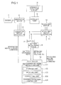
- FIG. 1 is a diagram illustrating a system configuration when a hybrid construction machine according to an embodiment is applied to a hybrid shovel.
- the hybrid shovel includes an engine 7, a generator motor 8, a hydraulic pump 9, a hydraulic actuator circuit 10, a battery 11, a generator motor controller 12, a controller 13 (an example of a control unit), a revolving motor 14, a revolving motor controller 15, and a battery monitoring device 16.
- the hydraulic pump 9 and the generator motor 8 that performs generator and motor actions are mechanically connected to the engine 7 serving as a power source.
- the generator motor 8 and the hydraulic pump 9 are driven by the engine 7.
- the hydraulic pump 9 is connected with the generator motor 8 interposed.
- Hydraulic actuator circuits 10 (only one is illustrated for simplicity of the drawing) corresponding to respective hydraulic actuators are connected to the hydraulic pump 9.
- a hydraulic actuator (not illustrated) is driven by the pressurized oil from the hydraulic pump 9.
- the power storage device (battery) 11 is connected to the generator motor 8 with the generator motor controller 12 interposed.
- the generator motor controller 12 controls charging and discharging of the battery 11 as a basic operation under the control of the controller 13 serving as a control unit.
- the generator motor controller 12 controls, for example, switching between the generator action and the motor action of the generator motor 8.
- the generator motor controller 12 causes the generator motor 8 to operate as a generator. Moreover, the generator motor controller 12 charges the battery 11 with the power generated by the generator motor 8 that operates as a generator. On the other hand, when the charging rate of the battery 11 is higher than the predetermined level, the generator motor controller 12 causes the generator motor 8 to operate as a motor. Moreover, the generator motor controller 12 drives the generator motor 8 with the power stored in the battery 11 to cause the generator motor 8 to assist the engine 7.
- the generator motor controller 12 receives a generator motor torque command corresponding to an operation of an operating lever (not illustrated) from the controller 13 and controls the operation of the generator motor 8 based on the received generator motor torque command.
- the revolving motor 14 serving as a revolving driving source is provided in the hybrid shovel.
- the revolving motor 14 is driven with the power of the battery 11. Due to this, the upper revolving body 2 illustrated in FIG. 8 revolves and the battery 11 is charged with regeneration power generated in the revolving motor 14 when the revolving decelerates.
- the revolving motor 14 is connected to the battery 11 with the revolving motor controller 15 interposed.
- the revolving motor controller 15 receives a revolving motor torque command corresponding to an operation of a revolving operating lever (not illustrated) from the controller 13 and controls the operation of the revolving motor 14 based on the received revolving motor torque command.
- the battery monitoring device 16 that detects a voltage (the voltage of each cell) and a charging rate (SOC: State of Charge) of the battery 11 is provided in the hybrid shovel.
- the battery monitoring device 16 provides to the controller 13 inputs of the detected voltage Vm and the detected charging rate.
- the controller 13 corrects an upper-limit working charging rate according to the degree of progress of deterioration of the battery 11 and controls the charging of the battery 11 based on the corrected upper-limit working charging rate.
- the controller 13 includes a processor such as an application specific integrated circuit (ASIC), a field-programmable gate array (FPGA), or a CPU, a ROM, a RAM, and a rewritable storage device such as an EEPROM, for example.
- ASIC application specific integrated circuit
- FPGA field-programmable gate array
- CPU central processing unit
- ROM read-only memory
- RAM random access memory
- EEPROM electrically erasable programmable read-only memory
- EEPROM electrically erasable programmable read-only memory
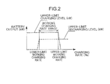
- FIG. 2 is a graph illustrating a "working charging rate range” that is set in advance as the range of charging rates usable for the new (non-deteriorated) battery 11.
- the vertical axis represents a battery output (unit: kW) and the horizontal axis represents the charging rate of the battery 11.
- the battery output indicates the power output by the battery 11.
- the "working charging rate range” is the range of charging rates between "lower-limit working charging rate” and "upper-limit working charging rate”.
- the “lower-limit working charging rate” is the lower limit of the practically usable charging rate of the battery 11.
- the battery 11 is controlled so that the charging rate during discharging is higher than the "lower-limit working charging rate".
- the "upper-limit working charging rate” is the upper limit of the practically usable charging rate of the battery 11 and has a value lower than 100%, for example.
- the battery 11 is controlled so that the charging rate during charging does not exceed the "upper-limit working charging rate".
- An “upper-limit charging level” indicates a maximum power that the battery 11 can apply during charging and has a value corresponding to the charging rate.
- An “upper-limit discharging level” indicates a maximum power that the battery 11 can output during discharging and has a value corresponding to the charging rate.
- the "upper-limit charging level” is set to a constant value in the region equal to or lower than the "upper-limit working charging rate” and is set to "0" after decreasing abruptly in the region higher than the "upper-limit working charging rate”. Due to this, the charging rate of the battery 11 is substantially prevented from exceeding the "upper-limit working charging rate," and the battery 11 can absorb the regeneration energy of the generator motor 8 and the revolving motor 14 during regeneration.
- the "upper-limit discharging level” is set to a constant value in the region higher than the "lower-limit working charging rate” and is set to "0" after decreasing abruptly in the region equal to or lower than the "lower-limit working charging rate". Due to this, the charging rate of the battery 11 is substantially prevented from becoming equal to or lower than the "lower-limit working charging rate," and the battery 11 is prevented from becoming unable to drive the generator motor 8 and the revolving motor 14.
- the "upper-limit charging level” is higher than the "upper-limit discharging level”.
- the controller 13 includes the following constituent elements.
- the controller 13 includes a difference voltage calculating unit 131, a storage unit 132, an updating unit 133, a correcting unit 134, and a charging/discharging control unit 135.
- the difference voltage calculating unit 131 calculates a difference voltage ⁇ V between the upper-limit working voltage Vu and the detected voltage Vm of the battery 11 detected by the battery monitoring device 16.
- the storage unit 132 stores the difference voltage ⁇ V.
- the updating unit 133 updates the storage unit 132 by selecting the lower one of the calculated difference voltage ⁇ V and the stored difference voltage ⁇ V stored in the storage unit 132.
- the lower-one selection means selecting the smaller difference voltage ⁇ V among the calculated difference voltage ⁇ V and the stored difference voltage ⁇ V.
- the stored value means the difference voltage ⁇ V selected as the lower one among the values calculated by that time.
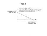
- the correcting unit 134 calculates a correction value corresponding to the selected difference voltage ⁇ V by referring to a correction value calculation map illustrated in FIG. 3 in which a relation between the difference voltage ⁇ V and the "correction value" is determined in advance.
- FIG. 3 is a graph schematically illustrating the correction value calculation map, in which the vertical axis represents the correction value (unit: %) of the "upper-limit working charging rate" and the horizontal axis represents the difference voltage ⁇ V.
- the correction value calculation map defines the difference voltage ⁇ V and the correction value so that the larger the difference voltage ⁇ V, the smaller the correction value.
- the correction value calculation map is created so that the correction value decreases at a predetermined constant slope as the difference voltage ⁇ V increases.
- the correcting unit 134 corrects the "upper-limit working charging rate" so as to decrease as the difference voltage ⁇ V decreases.
- the correction value is set to 100%, for example.
- the correction value is set such that the correction value decreases at a constant inclination from 100% as the difference voltage ⁇ V increases.
- the correcting unit 134 may correct the upper-limit working charging rate by multiplying the initial "upper-limit working charging rate" by the correction value.
- the charging/discharging control unit 135 determines the "upper-limit charging level" of the battery 11 so as not to exceed the corrected "upper-limit working charging rate". Specifically, during regeneration, the charging/discharging control unit 135 determines the "upper-limit charging level” corresponding to the present charging rate of the battery 11 detected by the battery monitoring device 16 using the "corrected upper-limit charging level” illustrated in FIG. 4 . Moreover, the controller 13 may control the generator motor controller 12 and the revolving motor controller 15 so that the battery voltage does not exceed the determined "upper-limit charging level".
- FIG. 5 is a graph illustrating the behavior of the battery voltage during regeneration.
- the graph of "initial upper-limit working charging rate" indicated by a solid line illustrates the behavior of the battery voltage of a new battery in which no correction is applied, corresponding to FIG. 2 .
- the vertical axis represents a voltage and the horizontal axis represent time.
- the graph of "corrected upper-limit working charging rate" indicated by a one-dot-chain line illustrates the behavior of the battery voltage in which correction is applied with a battery deterioration, corresponding to FIG. 4 .
- the hybrid shovel of the present embodiment applies correction even after the battery deterioration progresses to suppress the battery voltage during regeneration to be equal to or lower than the upper-limit working voltage Vu. In this way, it is possible to prevent the occurrence of an overvoltage state.
- the battery voltage at the start of regeneration is lower than the battery voltage before correction by the voltage ⁇ . Due to this, during regeneration, the battery voltage is prevented from exceeding the upper-limit working voltage Vu. As a result, it is possible to prevent the battery voltage from entering an overvoltage region.
- FIG. 6 is a flowchart illustrating a normal process routine and FIG. 7 is a flowchart illustrating a shut-off process routine during a key-off period.
- the battery monitoring device 16 detects a battery voltage.
- the battery monitoring device 16 detects a battery voltage (cell voltage) of each cell.
- step S2 the difference voltage calculating unit 131 selects the largest value of the detected cell voltages.
- step S3 the difference voltage calculating unit 131 calculates a difference voltage ⁇ V between the largest cell voltage and the upper-limit working voltage Vu.
- step S4 the updating unit 133 selects the lower one of the calculated difference voltage ⁇ V and the stored difference voltage ⁇ V.
- step S5 the correcting unit 134 calculates the correction value of the upper-limit working charging rate corresponding to the selected difference voltage ⁇ V using the correction value calculation map ( FIG. 3 ).
- step S6 the charging/discharging control unit 135 sets the corrected upper-limit working charging rate.
- step S7 the charging/discharging control unit 135 determines the upper-limit charging level based on the corrected upper-limit working charging rate and ends the process.
- the flowchart of FIG. 6 is executed periodically when the key of the hybrid shovel is on, for example.
- the shut-off process illustrated in FIG. 7 is executed during a key-off period in which the key of the hybrid shovel is off.
- the updating unit 133 stores the finally selected difference voltage ⁇ V in the storage unit 132.
- the hybrid shovel of the present embodiment selects the lower one of the calculated difference voltage ⁇ V and the stored difference voltage ⁇ V and corrects the upper-limit working charging rate based on the selected difference voltage ⁇ V. That is, the hybrid shovel of the present embodiment corrects the upper-limit working charging rate based on the latest deterioration information. Due to this, the hybrid shovel of the present embodiment can perform precise charging control by reflecting the degree of progress of deterioration accurately.
- the battery voltage is monitored in respective cells that form the battery 11, the difference voltage ⁇ V is calculated using the largest cell voltage, and the lower one of the calculated difference voltage ⁇ V and the stored difference voltage ⁇ V is selected.
- the difference voltage ⁇ V is calculated using the largest cell voltage, and the lower one of the calculated difference voltage ⁇ V and the stored difference voltage ⁇ V is selected.
- the present invention can be applied to other hybrid construction machines without being limited to the hybrid shovel.
- the difference voltage may be calculated using the voltage of the entire battery 11.
- the upper-limit working voltage may have a value corresponding to one cell.
- the upper-limit working voltage may have a value corresponding to the voltage of the battery 11.
- the difference voltage between the upper-limit working voltage of the power storage device and the detected voltage of the power storage device indicates the degree of deterioration of the power storage device.
- the lower one of the calculated difference voltage and the stored difference voltage is selected, it is possible to understand the state of progress of the deterioration of the power storage device accurately.
- the power storage device may include a plurality of cells
- the battery monitoring device may detect the voltage of each of the cells
- the difference voltage calculating unit may calculate the difference voltage, using a largest voltage among voltages detected by the battery monitoring device.
- the hybrid construction machine may stop due to a voltage abnormality, and the entire power storage device may become unusable.
- the difference voltage calculating unit selects the largest one of the voltages detected in respective cells that form the power storage device and calculates the difference voltage using the largest value.
- the voltage is monitored in respective cells in this manner, the difference voltage is calculated using the largest cell voltage, and the lower one of the difference voltages is selected.
- it is possible to perform charging control more precisely by taking a variation in the degrees of deterioration between cells into account.
- the correcting unit may determine a correction value corresponding to the selected difference voltage, using a correction value calculation map in which a relation between the difference voltage and the correction value is predetermined, so that the correction value of the upper-limit working charging rate decreases as the difference voltage increases, and the correcting unit may correct the upper-limit working charging rate, using the determined correction value.
- the correction value corresponding to the difference voltage is determined using the correction value calculation map in which the relation between the difference voltage and the correction value is set in advance, and the upper-limit working charging rate is corrected using the determined correction value. Due to this, it is possible to calculate the correction value accurately and quickly.
- the hybrid construction machine may further include:
- a hybrid construction machine detects the voltage of each cell that forms a battery, calculates a difference voltage between the detected voltage and a predetermined upper-limit working voltage, selects the lower one of the calculated difference voltage and a stored difference voltage, corrects an upper-limit working charging rate to decrease as the selected difference voltage decreases, and controls charging of the battery, based on the corrected upper-limit working charging rate.
Landscapes
- Engineering & Computer Science (AREA)
- General Engineering & Computer Science (AREA)
- Civil Engineering (AREA)
- Structural Engineering (AREA)
- Mining & Mineral Resources (AREA)
- Physics & Mathematics (AREA)
- Power Engineering (AREA)
- General Physics & Mathematics (AREA)
- Fluid Mechanics (AREA)
- Mechanical Engineering (AREA)
- Chemical & Material Sciences (AREA)
- Analytical Chemistry (AREA)
- Secondary Cells (AREA)
- Charge And Discharge Circuits For Batteries Or The Like (AREA)
- Operation Control Of Excavators (AREA)
- Electric Propulsion And Braking For Vehicles (AREA)
Abstract
Description
- The present invention relates to a hybrid construction machine such as a hybrid shovel which is operated by the power of an engine and the power of a power storage device.
- Description will be made of the background art by way of a hybrid shovel as an example.
- In a hybrid shovel, from the perspective of protecting a power storage device, a charging rate that does not exceed an "upper-limit working voltage" of the power storage device even when supposed maximum regeneration energy (maximum regeneration energy) generated by a revolving operation or the like is absorbed is set in advance as an "upper-limit working charging rate". Moreover, the hybrid shovel controls the power storage device so that the upper limit of the charging rate of the power storage device is determined so as not to exceed the upper-limit working charging rate (see Japanese Unexamined Patent Publication No.
2010-41828 - The "power storage device" in the present specification includes both a secondary battery (a so-called "battery") such as a lithium-ion battery and a capacitor (an electric double-layer capacitor). However, for the sake of convenience, in the embodiment of the present invention, the power storage device will be referred to as a "battery".
- Moreover, the "upper-limit working voltage" refers to a battery voltage (that is, an upper limit of a practical battery voltage) at which the hybrid shovel stops due to a battery abnormality if the voltage exceeds the upper-limit working voltage.
- Here, when a battery deteriorates with use as well as aging, an internal resistance thereof increases and the battery voltage increases. Thus, an overvoltage state may occur.
- On the other hand, it is technically difficult to detect a deterioration of a battery appearing as an increase in the internal resistance directly.
- As a countermeasure to this problem, in the related art disclosed in Japanese Unexamined Patent Publication No.
2010-41828 2010-41828 - However, the deterioration progresses with use, and for example, the degree of deterioration of the battery is different depending on whether the battery is a new product or has been used for a long period. However, in Japanese Unexamined Patent Publication No.
2010-41828 - On the other hand, Japanese Unexamined Patent Publication No.
2013-119761 - However, the accumulated operating time and the battery voltage are merely indicators of deterioration (that is, roughly estimated signs) and do not always indicate the degree of deterioration directly.
- Moreover, the state of progress of battery deterioration is not constant but is different depending on the use condition (for example, a temperature environment), the use frequency, and the like.
- Thus, in the related art disclosed in Japanese Unexamined Patent Publication No.
2013-119761 - Therefore, an object of the present invention is to provide a hybrid construction machine capable of detecting the degree of deterioration of a power storage device accurately and perform precise charging control by reflecting the degree of deterioration.
- A hybrid construction machine according to an aspect of the present invention is
a hybrid construction machine including: - a hydraulic pump that serves as a hydraulic power source of a hydraulic actuator;
- a generator motor;
- an engine that is connected to the hydraulic pump and the generator motor;
- a power storage device;
- a generator motor controller that assists the engine by a motor action of the generator motor with the aid of power of the power storage device;
- a control unit that controls charging and discharging of the power storage device; and
- a battery monitoring device that detects a voltage of the power storage device, wherein the control unit includes:
- a difference voltage calculating unit that calculates a difference voltage, which is a difference between an upper-limit working voltage that is set in advance as an upper limit of a usable voltage of the power storage device, and the voltage of the power storage device detected by the battery monitoring device;
- a storage unit that stores the difference voltage;
- an updating unit that updates the storage unit by selecting the lower one of the calculated difference voltage and the stored difference voltage stored in the storage unit;
- a correcting unit that corrects an upper-limit working charging rate, which is set in advance as an upper limit of a charging rate usable for the power storage device, to decrease as the selected difference voltage decreases; and
- a charging/discharging control unit that controls charging of the power storage device, based on the corrected upper-limit working charging rate.
- According to this configuration, it is possible to detect the degree of deterioration of a power storage device accurately and perform precise charging control by reflecting the degree of deterioration.
-
-
FIG. 1 is a diagram illustrating a system configuration when a hybrid construction machine according to an embodiment is applied to a hybrid shovel; -
FIG. 2 is a graph illustrating a "working charging rate range" that is set in advance as the range of charging rates usable for a new (non-deteriorated) battery; -
FIG. 3 is a graph schematically illustrating a correction value calculation map used in the embodiment; -
FIG. 4 is a graph illustrating a corrected "working charging rate range"; -
FIG. 5 is a graph illustrating the behavior of a battery voltage during regeneration; -
FIG. 6 is a flowchart for describing a normal process routine according to the embodiment; -
FIG. 7 is a flowchart for describing the content of a shut-off process according to the embodiment; and -
FIG. 8 is a schematic side view of a hybrid shovel to which the present invention is applied. - The invention is now described, by way of example, with reference to the accompanying drawings.
- Hereinafter, a case in which a hybrid construction machine according to an embodiment of the present invention is applied to a hybrid shovel will be described by way of example.
- As illustrated in
FIG. 8 , a hybrid shovel includes a lower travelingbody 1 and an upper revolvingbody 2 mounted on the lower travelingbody 1 so as to freely revolve about an axis X that is vertical to the ground. A workingattachment 6 including aboom 3, anarm 4, and abucket 5 is attached to the upper revolvingbody 2. - Moreover, in the hybrid shovel, a hydraulic pump and a generator motor are connected to an engine serving as a power source. A hydraulic actuator is driven by the hydraulic pump and a power storage device is charged by the generator action of the generator motor. With the power of the power storage device, the generator motor operates as a motor and assists the engine at an appropriate time.
-
FIG. 1 is a diagram illustrating a system configuration when a hybrid construction machine according to an embodiment is applied to a hybrid shovel. - As illustrated in
FIG. 1 , the hybrid shovel includes anengine 7, agenerator motor 8, ahydraulic pump 9, ahydraulic actuator circuit 10, abattery 11, agenerator motor controller 12, a controller 13 (an example of a control unit), a revolvingmotor 14, a revolvingmotor controller 15, and abattery monitoring device 16. - In such a hybrid shovel as illustrated in the drawing, the
hydraulic pump 9 and thegenerator motor 8 that performs generator and motor actions are mechanically connected to theengine 7 serving as a power source. Thegenerator motor 8 and thehydraulic pump 9 are driven by theengine 7. InFIG. 1 , thehydraulic pump 9 is connected with thegenerator motor 8 interposed. - Hydraulic actuator circuits 10 (only one is illustrated for simplicity of the drawing) corresponding to respective hydraulic actuators are connected to the
hydraulic pump 9. A hydraulic actuator (not illustrated) is driven by the pressurized oil from thehydraulic pump 9. - The power storage device (battery) 11 is connected to the
generator motor 8 with thegenerator motor controller 12 interposed. Thegenerator motor controller 12 controls charging and discharging of thebattery 11 as a basic operation under the control of thecontroller 13 serving as a control unit. Moreover, thegenerator motor controller 12 controls, for example, switching between the generator action and the motor action of thegenerator motor 8. - That is, during operation of the hybrid shovel, when a charging rate of the
battery 11 decreases to a predetermined level or lower, thegenerator motor controller 12 causes thegenerator motor 8 to operate as a generator. Moreover, thegenerator motor controller 12 charges thebattery 11 with the power generated by thegenerator motor 8 that operates as a generator. On the other hand, when the charging rate of thebattery 11 is higher than the predetermined level, thegenerator motor controller 12 causes thegenerator motor 8 to operate as a motor. Moreover, thegenerator motor controller 12 drives thegenerator motor 8 with the power stored in thebattery 11 to cause thegenerator motor 8 to assist theengine 7. - The
generator motor controller 12 receives a generator motor torque command corresponding to an operation of an operating lever (not illustrated) from thecontroller 13 and controls the operation of thegenerator motor 8 based on the received generator motor torque command. - Moreover, the revolving
motor 14 serving as a revolving driving source is provided in the hybrid shovel. The revolvingmotor 14 is driven with the power of thebattery 11. Due to this, the upper revolvingbody 2 illustrated inFIG. 8 revolves and thebattery 11 is charged with regeneration power generated in the revolvingmotor 14 when the revolving decelerates. - The revolving
motor 14 is connected to thebattery 11 with the revolvingmotor controller 15 interposed. The revolvingmotor controller 15 receives a revolving motor torque command corresponding to an operation of a revolving operating lever (not illustrated) from thecontroller 13 and controls the operation of the revolvingmotor 14 based on the received revolving motor torque command. - Moreover, the
battery monitoring device 16 that detects a voltage (the voltage of each cell) and a charging rate (SOC: State of Charge) of thebattery 11 is provided in the hybrid shovel. Thebattery monitoring device 16 provides to thecontroller 13 inputs of the detected voltage Vm and the detected charging rate. - The
controller 13 corrects an upper-limit working charging rate according to the degree of progress of deterioration of thebattery 11 and controls the charging of thebattery 11 based on the corrected upper-limit working charging rate. - The charging control will be described in detail. The
controller 13 includes a processor such as an application specific integrated circuit (ASIC), a field-programmable gate array (FPGA), or a CPU, a ROM, a RAM, and a rewritable storage device such as an EEPROM, for example. -
FIG. 2 is a graph illustrating a "working charging rate range" that is set in advance as the range of charging rates usable for the new (non-deteriorated)battery 11. InFIG. 2 , the vertical axis represents a battery output (unit: kW) and the horizontal axis represents the charging rate of thebattery 11. The battery output indicates the power output by thebattery 11. The "working charging rate range" is the range of charging rates between "lower-limit working charging rate" and "upper-limit working charging rate". - The "lower-limit working charging rate" is the lower limit of the practically usable charging rate of the
battery 11. Thebattery 11 is controlled so that the charging rate during discharging is higher than the "lower-limit working charging rate". - The "upper-limit working charging rate" is the upper limit of the practically usable charging rate of the
battery 11 and has a value lower than 100%, for example. Thebattery 11 is controlled so that the charging rate during charging does not exceed the "upper-limit working charging rate". - An "upper-limit charging level" indicates a maximum power that the
battery 11 can apply during charging and has a value corresponding to the charging rate. An "upper-limit discharging level" indicates a maximum power that thebattery 11 can output during discharging and has a value corresponding to the charging rate. - In the example of
FIG. 2 , the "upper-limit charging level" is set to a constant value in the region equal to or lower than the "upper-limit working charging rate" and is set to "0" after decreasing abruptly in the region higher than the "upper-limit working charging rate". Due to this, the charging rate of thebattery 11 is substantially prevented from exceeding the "upper-limit working charging rate," and thebattery 11 can absorb the regeneration energy of thegenerator motor 8 and the revolvingmotor 14 during regeneration. - Moreover, the "upper-limit discharging level" is set to a constant value in the region higher than the "lower-limit working charging rate" and is set to "0" after decreasing abruptly in the region equal to or lower than the "lower-limit working charging rate". Due to this, the charging rate of the
battery 11 is substantially prevented from becoming equal to or lower than the "lower-limit working charging rate," and thebattery 11 is prevented from becoming unable to drive thegenerator motor 8 and the revolvingmotor 14. The "upper-limit charging level" is higher than the "upper-limit discharging level". - When the
battery 11 deteriorates with use, since the internal resistance of thebattery 11 increases, the deterioration of thebattery 11 appears as an increase in the voltage (battery voltage) of thebattery 11. - Thus, with the progress of the deterioration of the
battery 11, a difference (difference voltage ΔV=Vu-Vm) between the upper limit (the upper-limit working voltage Vu) of the usable battery voltage and the detected battery voltage Vm decreases. As a result, the possibility that an overvoltage state in which the detected voltage Vm exceeds the upper-limit working voltage Vu occurs during regeneration increases. - In the present embodiment, the
controller 13 includes the following constituent elements. - The
controller 13 includes a differencevoltage calculating unit 131, astorage unit 132, an updatingunit 133, a correctingunit 134, and a charging/dischargingcontrol unit 135. - The difference
voltage calculating unit 131 calculates a difference voltage ΔV between the upper-limit working voltage Vu and the detected voltage Vm of thebattery 11 detected by thebattery monitoring device 16. - The
storage unit 132 stores the difference voltage ΔV. - The updating
unit 133 updates thestorage unit 132 by selecting the lower one of the calculated difference voltage ΔV and the stored difference voltage ΔV stored in thestorage unit 132. Here, the lower-one selection means selecting the smaller difference voltage ΔV among the calculated difference voltage ΔV and the stored difference voltage ΔV. Moreover, the stored value means the difference voltage ΔV selected as the lower one among the values calculated by that time. - The correcting
unit 134 calculates a correction value corresponding to the selected difference voltage ΔV by referring to a correction value calculation map illustrated inFIG. 3 in which a relation between the difference voltage ΔV and the "correction value" is determined in advance. -
FIG. 3 is a graph schematically illustrating the correction value calculation map, in which the vertical axis represents the correction value (unit: %) of the "upper-limit working charging rate" and the horizontal axis represents the difference voltage ΔV. As illustrated inFIG. 3 , the correction value calculation map defines the difference voltage ΔV and the correction value so that the larger the difference voltage ΔV, the smaller the correction value. In the example ofFIG. 3 , the correction value calculation map is created so that the correction value decreases at a predetermined constant slope as the difference voltage ΔV increases. - As illustrated in
FIG. 4 , the correctingunit 134 corrects the "upper-limit working charging rate" so as to decrease as the difference voltage ΔV decreases. In the example ofFIG. 3 , when thebattery 11 is a new product, the correction value is set to 100%, for example. Moreover, the correction value is set such that the correction value decreases at a constant inclination from 100% as the difference voltage ΔV increases. Thus, the correctingunit 134 may correct the upper-limit working charging rate by multiplying the initial "upper-limit working charging rate" by the correction value. - The charging/discharging
control unit 135 determines the "upper-limit charging level" of thebattery 11 so as not to exceed the corrected "upper-limit working charging rate". Specifically, during regeneration, the charging/dischargingcontrol unit 135 determines the "upper-limit charging level" corresponding to the present charging rate of thebattery 11 detected by thebattery monitoring device 16 using the "corrected upper-limit charging level" illustrated inFIG. 4 . Moreover, thecontroller 13 may control thegenerator motor controller 12 and the revolvingmotor controller 15 so that the battery voltage does not exceed the determined "upper-limit charging level". - The result of this control is illustrated in
FIG. 5 . -
FIG. 5 is a graph illustrating the behavior of the battery voltage during regeneration. In the drawing, the graph of "initial upper-limit working charging rate" indicated by a solid line illustrates the behavior of the battery voltage of a new battery in which no correction is applied, corresponding toFIG. 2 . InFIG. 5 , the vertical axis represents a voltage and the horizontal axis represent time. - The graph of "corrected upper-limit working charging rate" indicated by a one-dot-chain line illustrates the behavior of the battery voltage in which correction is applied with a battery deterioration, corresponding to
FIG. 4 . - As illustrated in the drawing, the hybrid shovel of the present embodiment applies correction even after the battery deterioration progresses to suppress the battery voltage during regeneration to be equal to or lower than the upper-limit working voltage Vu. In this way, it is possible to prevent the occurrence of an overvoltage state.
- That is, in the hybrid shovel of the present embodiment, since the "upper-limit working charging rate" is corrected so as to decrease as the difference voltage ΔV decreases, the battery voltage at the start of regeneration is lower than the battery voltage before correction by the voltage α. Due to this, during regeneration, the battery voltage is prevented from exceeding the upper-limit working voltage Vu. As a result, it is possible to prevent the battery voltage from entering an overvoltage region.
- The operations will be described based on flowcharts.
-
FIG. 6 is a flowchart illustrating a normal process routine andFIG. 7 is a flowchart illustrating a shut-off process routine during a key-off period. - As a normal process, in step S1 of
FIG. 6 , thebattery monitoring device 16 detects a battery voltage. Here, thebattery monitoring device 16 detects a battery voltage (cell voltage) of each cell. - In step S2, the difference
voltage calculating unit 131 selects the largest value of the detected cell voltages. In step S3, the differencevoltage calculating unit 131 calculates a difference voltage ΔV between the largest cell voltage and the upper-limit working voltage Vu. - Subsequently, in step S4, the updating
unit 133 selects the lower one of the calculated difference voltage ΔV and the stored difference voltage ΔV. In step S5, the correctingunit 134 calculates the correction value of the upper-limit working charging rate corresponding to the selected difference voltage ΔV using the correction value calculation map (FIG. 3 ). In step S6, the charging/dischargingcontrol unit 135 sets the corrected upper-limit working charging rate. In step S7, the charging/dischargingcontrol unit 135 determines the upper-limit charging level based on the corrected upper-limit working charging rate and ends the process. The flowchart ofFIG. 6 is executed periodically when the key of the hybrid shovel is on, for example. - On the other hand, the shut-off process illustrated in
FIG. 7 is executed during a key-off period in which the key of the hybrid shovel is off. In the shut-off process, the updatingunit 133 stores the finally selected difference voltage ΔV in thestorage unit 132. - In this manner, the hybrid shovel of the present embodiment selects the lower one of the calculated difference voltage ΔV and the stored difference voltage ΔV and corrects the upper-limit working charging rate based on the selected difference voltage ΔV. That is, the hybrid shovel of the present embodiment corrects the upper-limit working charging rate based on the latest deterioration information. Due to this, the hybrid shovel of the present embodiment can perform precise charging control by reflecting the degree of progress of deterioration accurately.
- That is, it is possible to prevent the
battery 11 from entering an overvoltage state (unusable state) and to obviate the possibility that the machine stops abnormally. - In this case, the battery voltage is monitored in respective cells that form the
battery 11, the difference voltage ΔV is calculated using the largest cell voltage, and the lower one of the calculated difference voltage ΔV and the stored difference voltage ΔV is selected. Thus, it is possible to perform charging control more precisely by taking a variation in the degrees of deterioration between cells into account. - The present invention can be applied to other hybrid construction machines without being limited to the hybrid shovel.
- In the flowchart of
FIG. 6 , although the difference voltage is calculated using the largest cell voltage, the difference voltage may be calculated using the voltage of theentire battery 11. When the difference voltage ΔV is calculated using the largest cell voltage, the upper-limit working voltage may have a value corresponding to one cell. Moreover, when the difference voltage is calculated using the voltage of thebattery 11, the upper-limit working voltage may have a value corresponding to the voltage of thebattery 11. - A hybrid construction machine according to the embodiment includes:
- a hydraulic pump that serves as a hydraulic power source of a hydraulic actuator;
- a generator motor;
- an engine that is connected to the hydraulic pump and the generator motor;
- a power storage device;
- a generator motor controller that assists the engine by a motor action of the generator motor with the aid of power of the power storage device;
- a control unit that controls charging and discharging of the power storage device; and
- a battery monitoring device that detects a voltage of the power storage device, wherein
- the control unit includes:
- a difference voltage calculating unit that calculates a difference voltage, which is a difference between an upper-limit working voltage that is set in advance as an upper limit of a usable voltage of the power storage device, and the voltage of the power storage device detected by the battery monitoring device;
- a storage unit that stores the difference voltage;
- an updating unit that updates the storage unit by selecting the lower one of the calculated difference voltage and the stored difference voltage stored in the storage unit;
- a correcting unit that corrects an upper-limit working charging rate, which is set in advance as an upper limit of a charging rate usable for the power storage device, to decrease as the selected difference voltage decreases; and
- a charging/discharging control unit that controls charging of the power storage device, based on the corrected upper-limit working charging rate.
- Here, the difference voltage between the upper-limit working voltage of the power storage device and the detected voltage of the power storage device indicates the degree of deterioration of the power storage device. In this configuration, since the lower one of the calculated difference voltage and the stored difference voltage is selected, it is possible to understand the state of progress of the deterioration of the power storage device accurately.
- Moreover, in this configuration, since the upper-limit working charging rate is corrected based on the selected difference voltage (that is, the latest deterioration information), it is possible to perform precise charging control by reflecting the degree of progress of deterioration accurately.
- Thus, in this configuration, it is possible to prevent the power storage device from entering an overvoltage state (unusable state) and to obviate the possibility that the hybrid construction machine stops abnormally.
- In the hybrid construction machine,
the power storage device may include a plurality of cells,
the battery monitoring device may detect the voltage of each of the cells, and
the difference voltage calculating unit may calculate the difference voltage, using a largest voltage among voltages detected by the battery monitoring device. - Since the internal resistance indicating the deterioration of respective cells varies from cell to cell, when an overvoltage state due to a deterioration occurs in a certain cell, the hybrid construction machine may stop due to a voltage abnormality, and the entire power storage device may become unusable.
- Thus, the difference voltage calculating unit selects the largest one of the voltages detected in respective cells that form the power storage device and calculates the difference voltage using the largest value.
- The voltage is monitored in respective cells in this manner, the difference voltage is calculated using the largest cell voltage, and the lower one of the difference voltages is selected. Thus, it is possible to perform charging control more precisely by taking a variation in the degrees of deterioration between cells into account.
- In the hybrid construction machine,
the correcting unit may determine a correction value corresponding to the selected difference voltage, using a correction value calculation map in which a relation between the difference voltage and the correction value is predetermined, so that the correction value of the upper-limit working charging rate decreases as the difference voltage increases, and the correcting unit may correct the upper-limit working charging rate, using the determined correction value. - According to this configuration, the correction value corresponding to the difference voltage is determined using the correction value calculation map in which the relation between the difference voltage and the correction value is set in advance, and the upper-limit working charging rate is corrected using the determined correction value. Due to this, it is possible to calculate the correction value accurately and quickly.
- The hybrid construction machine may further include:
- a revolving body;
- a revolving motor that revolves the revolving body; and
- a revolving motor controller that causes the revolving motor to operates as a motor with the aid of the power of the power storage device and causes the power storage device to be charged with a generator action of the revolving motor.
- According to this configuration, in the hybrid construction machine having the revolving motor, it is possible to perform precise charging control by reflecting the degree of progress of deterioration accurately.
- This application is based on Japanese Patent application No.
2014-175063 - Although the present invention has been fully described by way of example with reference to the accompanying drawings, it is to be understood that various changes and modifications will be apparent to those skilled in the art. Therefore, unless otherwise such changes and modifications depart from the scope of the present invention hereinafter defined, they should be construed as being included therein.
- A hybrid construction machine detects the voltage of each cell that forms a battery, calculates a difference voltage between the detected voltage and a predetermined upper-limit working voltage, selects the lower one of the calculated difference voltage and a stored difference voltage, corrects an upper-limit working charging rate to decrease as the selected difference voltage decreases, and controls charging of the battery, based on the corrected upper-limit working charging rate.
Claims (4)
- A hybrid construction machine comprising:a hydraulic pump that serves as a hydraulic power source of a hydraulic actuator;a generator motor;an engine that is connected to the hydraulic pump and the generator motor;a power storage device;a generator motor controller that assists the engine by a motor action of the generator motor with the aid of power of the power storage device;a control unit that controls charging and discharging of the power storage device; anda battery monitoring device that detects a voltage of the power storage device, whereinthe control unit includes:a difference voltage calculating unit that calculates a difference voltage, which is a difference between an upper-limit working voltage that is set in advance as an upper limit of a usable voltage of the power storage device, and the voltage of the power storage device detected by the battery monitoring device;a storage unit that stores the difference voltage;an updating unit that updates the difference voltage which stored by the storage unit by selecting the lower one of the calculated difference voltage and the stored difference voltage stored in the storage unit;a correcting unit that corrects an upper-limit working charging rate, which is set in advance as an upper limit of a charging rate usable for the power storage device, to decrease as the selected difference voltage decreases; anda charging/discharging control unit that controls charging of the power storage device, based on the corrected upper-limit working charging rate.
- The hybrid construction machine according to claim 1, wherein
the power storage device includes a plurality of cells,
the battery monitoring device detects the voltage of each of the cells, and
the difference voltage calculating unit calculates the difference voltage, using a largest voltage among voltages detected by the battery monitoring device. - The hybrid construction machine according to claim 1 or 2, wherein
the correcting unit determines a correction value corresponding to the selected difference voltage, using a correction value calculation map in which a relation between the difference voltage and the correction value is predetermined, so that the correction value of the upper-limit working charging rate decreases as the difference voltage increases, and
the correcting unit corrects the upper-limit working charging rate, using the determined correction value. - The hybrid construction machine according to any one of claims 1 to 3, further comprising:a revolving body;a revolving motor that revolves the revolving body; anda revolving motor controller that causes the revolving motor to operate as a motor with the aid of the power of the power storage device and causes the power storage device to be charged with a generator action of the revolving motor.
Applications Claiming Priority (1)
| Application Number | Priority Date | Filing Date | Title |
|---|---|---|---|
| JP2014175063A JP6225856B2 (en) | 2014-08-29 | 2014-08-29 | Hybrid construction machinery |
Publications (3)
| Publication Number | Publication Date |
|---|---|
| EP2990542A2 true EP2990542A2 (en) | 2016-03-02 |
| EP2990542A3 EP2990542A3 (en) | 2016-05-11 |
| EP2990542B1 EP2990542B1 (en) | 2022-11-30 |
Family
ID=53969204
Family Applications (1)
| Application Number | Title | Priority Date | Filing Date |
|---|---|---|---|
| EP15181547.9A Active EP2990542B1 (en) | 2014-08-29 | 2015-08-19 | Hybrid construction machine |
Country Status (4)
| Country | Link |
|---|---|
| US (1) | US9726205B2 (en) |
| EP (1) | EP2990542B1 (en) |
| JP (1) | JP6225856B2 (en) |
| CN (1) | CN105386483B (en) |
Families Citing this family (3)
| Publication number | Priority date | Publication date | Assignee | Title |
|---|---|---|---|---|
| JP6401241B2 (en) * | 2014-03-06 | 2018-10-10 | 住友建機株式会社 | Excavator |
| JP6985216B2 (en) * | 2018-06-28 | 2021-12-22 | 日立建機株式会社 | Construction machinery management system |
| JP7375786B2 (en) * | 2021-03-26 | 2023-11-08 | トヨタ自動車株式会社 | All-solid-state lithium-ion battery control system |
Citations (2)
| Publication number | Priority date | Publication date | Assignee | Title |
|---|---|---|---|---|
| JP2010041828A (en) | 2008-08-05 | 2010-02-18 | Sumitomo Heavy Ind Ltd | Battery charging/discharging control method |
| JP2013119761A (en) | 2011-12-09 | 2013-06-17 | Kobelco Contstruction Machinery Ltd | Hybrid construction machine |
Family Cites Families (16)
| Publication number | Priority date | Publication date | Assignee | Title |
|---|---|---|---|---|
| JP3560867B2 (en) * | 1999-08-31 | 2004-09-02 | 本田技研工業株式会社 | Hybrid vehicle battery control device |
| JP3817141B2 (en) | 2000-12-05 | 2006-08-30 | 矢崎総業株式会社 | Deterioration degree determination method and apparatus for vehicle battery |
| JP2007155586A (en) | 2005-12-07 | 2007-06-21 | Sumitomo Heavy Ind Ltd | Working machine and method for starting operation of working machine |
| JP5186690B2 (en) * | 2008-03-21 | 2013-04-17 | 株式会社小松製作所 | Method and apparatus for determining deterioration state of power storage device in hybrid construction machine |
| US9212468B2 (en) | 2011-01-28 | 2015-12-15 | Sumitomo Heavy Industries, Ltd. | Excavator |
| CN103493328B (en) | 2011-01-28 | 2016-08-24 | 住友重机械工业株式会社 | Excavator |
| US9285432B2 (en) * | 2011-07-26 | 2016-03-15 | GM Global Technology Operations LLC | Method and system for controlling a vehicle battery |
| JP5568533B2 (en) * | 2011-09-22 | 2014-08-06 | 日立建機株式会社 | Construction machinery and its battery pack |
| JP5841399B2 (en) * | 2011-10-14 | 2016-01-13 | 日立建機株式会社 | Hybrid construction machine and control method thereof |
| JP5867039B2 (en) * | 2011-12-09 | 2016-02-24 | コベルコ建機株式会社 | Hybrid construction machinery |
| US20130169232A1 (en) * | 2011-12-30 | 2013-07-04 | Caterpillar Inc. | Methods and systems for monitoring and using an electrical energy-storage device |
| TWI476978B (en) * | 2012-04-11 | 2015-03-11 | Ship & Ocean Ind R & D Ct | The high-voltage battery charging simulation system and method |
| JP6013857B2 (en) * | 2012-09-28 | 2016-10-25 | 株式会社神戸製鋼所 | Secondary battery charge / discharge controller for construction machinery |
| PL2894486T3 (en) * | 2012-11-29 | 2020-11-30 | Lg Chem, Ltd. | Apparatus and method for estimating power of secondary battery comprising blended cathode material |
| JP6127550B2 (en) * | 2013-02-05 | 2017-05-17 | コベルコ建機株式会社 | Construction machinery |
| US20160248362A1 (en) * | 2015-02-19 | 2016-08-25 | Caterpillar Inc. | Hybrid Soft Switching for Current Regulation in Switched Reluctance Machines |
-
2014
- 2014-08-29 JP JP2014175063A patent/JP6225856B2/en not_active Expired - Fee Related
-
2015
- 2015-08-13 US US14/825,585 patent/US9726205B2/en not_active Expired - Fee Related
- 2015-08-19 EP EP15181547.9A patent/EP2990542B1/en active Active
- 2015-08-28 CN CN201510542998.2A patent/CN105386483B/en not_active Expired - Fee Related
Patent Citations (2)
| Publication number | Priority date | Publication date | Assignee | Title |
|---|---|---|---|---|
| JP2010041828A (en) | 2008-08-05 | 2010-02-18 | Sumitomo Heavy Ind Ltd | Battery charging/discharging control method |
| JP2013119761A (en) | 2011-12-09 | 2013-06-17 | Kobelco Contstruction Machinery Ltd | Hybrid construction machine |
Also Published As
| Publication number | Publication date |
|---|---|
| US20160061235A1 (en) | 2016-03-03 |
| EP2990542A3 (en) | 2016-05-11 |
| CN105386483B (en) | 2019-04-02 |
| CN105386483A (en) | 2016-03-09 |
| JP6225856B2 (en) | 2017-11-08 |
| JP2016052165A (en) | 2016-04-11 |
| EP2990542B1 (en) | 2022-11-30 |
| US9726205B2 (en) | 2017-08-08 |
Similar Documents
| Publication | Publication Date | Title |
|---|---|---|
| US8421415B2 (en) | Hybrid working machine having battery protecting function | |
| EP2204504B1 (en) | Hybrid working machine | |
| US9000716B2 (en) | Hybrid working machine and electric power accumulation controller | |
| KR101821326B1 (en) | Shovel | |
| US9077272B2 (en) | Slewing-type working machine | |
| JP6180249B2 (en) | Battery capacity estimation apparatus and battery capacity estimation method | |
| EP1720244A1 (en) | Power source device for working machine | |
| JP6162969B2 (en) | Work machine | |
| EP2602388B1 (en) | Battery controller for a hybrid construction machine | |
| EP3208387A1 (en) | Hybrid construction machinery | |
| EP2670020A1 (en) | Shovel | |
| CN103711171B (en) | Engineering machinery | |
| US9726205B2 (en) | Hybrid construction machine | |
| JP2015059814A (en) | SOC estimation apparatus and SOC estimation method | |
| JP4678353B2 (en) | Hybrid work machine | |
| JP7105665B2 (en) | construction machinery | |
| US9873349B2 (en) | Hybrid construction machine | |
| JP2013119761A (en) | Hybrid construction machine | |
| JP6578216B2 (en) | Hybrid construction machine |
Legal Events
| Date | Code | Title | Description |
|---|---|---|---|
| PUAI | Public reference made under article 153(3) epc to a published international application that has entered the european phase |
Free format text: ORIGINAL CODE: 0009012 |
|
| AK | Designated contracting states |
Kind code of ref document: A2 Designated state(s): AL AT BE BG CH CY CZ DE DK EE ES FI FR GB GR HR HU IE IS IT LI LT LU LV MC MK MT NL NO PL PT RO RS SE SI SK SM TR |
|
| AX | Request for extension of the european patent |
Extension state: BA ME |
|
| PUAL | Search report despatched |
Free format text: ORIGINAL CODE: 0009013 |
|
| AK | Designated contracting states |
Kind code of ref document: A3 Designated state(s): AL AT BE BG CH CY CZ DE DK EE ES FI FR GB GR HR HU IE IS IT LI LT LU LV MC MK MT NL NO PL PT RO RS SE SI SK SM TR |
|
| AX | Request for extension of the european patent |
Extension state: BA ME |
|
| RIC1 | Information provided on ipc code assigned before grant |
Ipc: E02F 9/20 20060101AFI20160407BHEP Ipc: G01R 31/36 20060101ALI20160407BHEP |
|
| STAA | Information on the status of an ep patent application or granted ep patent |
Free format text: STATUS: REQUEST FOR EXAMINATION WAS MADE |
|
| 17P | Request for examination filed |
Effective date: 20161109 |
|
| RBV | Designated contracting states (corrected) |
Designated state(s): AL AT BE BG CH CY CZ DE DK EE ES FI FR GB GR HR HU IE IS IT LI LT LU LV MC MK MT NL NO PL PT RO RS SE SI SK SM TR |
|
| STAA | Information on the status of an ep patent application or granted ep patent |
Free format text: STATUS: EXAMINATION IS IN PROGRESS |
|
| 17Q | First examination report despatched |
Effective date: 20210406 |
|
| GRAP | Despatch of communication of intention to grant a patent |
Free format text: ORIGINAL CODE: EPIDOSNIGR1 |
|
| STAA | Information on the status of an ep patent application or granted ep patent |
Free format text: STATUS: GRANT OF PATENT IS INTENDED |
|
| INTG | Intention to grant announced |
Effective date: 20220707 |
|
| GRAS | Grant fee paid |
Free format text: ORIGINAL CODE: EPIDOSNIGR3 |
|
| GRAA | (expected) grant |
Free format text: ORIGINAL CODE: 0009210 |
|
| STAA | Information on the status of an ep patent application or granted ep patent |
Free format text: STATUS: THE PATENT HAS BEEN GRANTED |
|
| AK | Designated contracting states |
Kind code of ref document: B1 Designated state(s): AL AT BE BG CH CY CZ DE DK EE ES FI FR GB GR HR HU IE IS IT LI LT LU LV MC MK MT NL NO PL PT RO RS SE SI SK SM TR |
|
| REG | Reference to a national code |
Ref country code: CH Ref legal event code: EP Ref country code: GB Ref legal event code: FG4D |
|
| REG | Reference to a national code |
Ref country code: AT Ref legal event code: REF Ref document number: 1534782 Country of ref document: AT Kind code of ref document: T Effective date: 20221215 |
|
| REG | Reference to a national code |
Ref country code: IE Ref legal event code: FG4D |
|
| REG | Reference to a national code |
Ref country code: DE Ref legal event code: R096 Ref document number: 602015081762 Country of ref document: DE |
|
| REG | Reference to a national code |
Ref country code: LT Ref legal event code: MG9D |
|
| REG | Reference to a national code |
Ref country code: NL Ref legal event code: MP Effective date: 20221130 |
|
| PG25 | Lapsed in a contracting state [announced via postgrant information from national office to epo] |
Ref country code: SE Free format text: LAPSE BECAUSE OF FAILURE TO SUBMIT A TRANSLATION OF THE DESCRIPTION OR TO PAY THE FEE WITHIN THE PRESCRIBED TIME-LIMIT Effective date: 20221130 Ref country code: PT Free format text: LAPSE BECAUSE OF FAILURE TO SUBMIT A TRANSLATION OF THE DESCRIPTION OR TO PAY THE FEE WITHIN THE PRESCRIBED TIME-LIMIT Effective date: 20230331 Ref country code: NO Free format text: LAPSE BECAUSE OF FAILURE TO SUBMIT A TRANSLATION OF THE DESCRIPTION OR TO PAY THE FEE WITHIN THE PRESCRIBED TIME-LIMIT Effective date: 20230228 Ref country code: LT Free format text: LAPSE BECAUSE OF FAILURE TO SUBMIT A TRANSLATION OF THE DESCRIPTION OR TO PAY THE FEE WITHIN THE PRESCRIBED TIME-LIMIT Effective date: 20221130 Ref country code: FI Free format text: LAPSE BECAUSE OF FAILURE TO SUBMIT A TRANSLATION OF THE DESCRIPTION OR TO PAY THE FEE WITHIN THE PRESCRIBED TIME-LIMIT Effective date: 20221130 Ref country code: ES Free format text: LAPSE BECAUSE OF FAILURE TO SUBMIT A TRANSLATION OF THE DESCRIPTION OR TO PAY THE FEE WITHIN THE PRESCRIBED TIME-LIMIT Effective date: 20221130 |
|
| REG | Reference to a national code |
Ref country code: AT Ref legal event code: MK05 Ref document number: 1534782 Country of ref document: AT Kind code of ref document: T Effective date: 20221130 |
|
| PG25 | Lapsed in a contracting state [announced via postgrant information from national office to epo] |
Ref country code: RS Free format text: LAPSE BECAUSE OF FAILURE TO SUBMIT A TRANSLATION OF THE DESCRIPTION OR TO PAY THE FEE WITHIN THE PRESCRIBED TIME-LIMIT Effective date: 20221130 Ref country code: PL Free format text: LAPSE BECAUSE OF FAILURE TO SUBMIT A TRANSLATION OF THE DESCRIPTION OR TO PAY THE FEE WITHIN THE PRESCRIBED TIME-LIMIT Effective date: 20221130 Ref country code: LV Free format text: LAPSE BECAUSE OF FAILURE TO SUBMIT A TRANSLATION OF THE DESCRIPTION OR TO PAY THE FEE WITHIN THE PRESCRIBED TIME-LIMIT Effective date: 20221130 Ref country code: IS Free format text: LAPSE BECAUSE OF FAILURE TO SUBMIT A TRANSLATION OF THE DESCRIPTION OR TO PAY THE FEE WITHIN THE PRESCRIBED TIME-LIMIT Effective date: 20230330 Ref country code: HR Free format text: LAPSE BECAUSE OF FAILURE TO SUBMIT A TRANSLATION OF THE DESCRIPTION OR TO PAY THE FEE WITHIN THE PRESCRIBED TIME-LIMIT Effective date: 20221130 Ref country code: GR Free format text: LAPSE BECAUSE OF FAILURE TO SUBMIT A TRANSLATION OF THE DESCRIPTION OR TO PAY THE FEE WITHIN THE PRESCRIBED TIME-LIMIT Effective date: 20230301 |
|
| PG25 | Lapsed in a contracting state [announced via postgrant information from national office to epo] |
Ref country code: NL Free format text: LAPSE BECAUSE OF FAILURE TO SUBMIT A TRANSLATION OF THE DESCRIPTION OR TO PAY THE FEE WITHIN THE PRESCRIBED TIME-LIMIT Effective date: 20221130 |
|
| PG25 | Lapsed in a contracting state [announced via postgrant information from national office to epo] |
Ref country code: SM Free format text: LAPSE BECAUSE OF FAILURE TO SUBMIT A TRANSLATION OF THE DESCRIPTION OR TO PAY THE FEE WITHIN THE PRESCRIBED TIME-LIMIT Effective date: 20221130 Ref country code: RO Free format text: LAPSE BECAUSE OF FAILURE TO SUBMIT A TRANSLATION OF THE DESCRIPTION OR TO PAY THE FEE WITHIN THE PRESCRIBED TIME-LIMIT Effective date: 20221130 Ref country code: EE Free format text: LAPSE BECAUSE OF FAILURE TO SUBMIT A TRANSLATION OF THE DESCRIPTION OR TO PAY THE FEE WITHIN THE PRESCRIBED TIME-LIMIT Effective date: 20221130 Ref country code: DK Free format text: LAPSE BECAUSE OF FAILURE TO SUBMIT A TRANSLATION OF THE DESCRIPTION OR TO PAY THE FEE WITHIN THE PRESCRIBED TIME-LIMIT Effective date: 20221130 Ref country code: CZ Free format text: LAPSE BECAUSE OF FAILURE TO SUBMIT A TRANSLATION OF THE DESCRIPTION OR TO PAY THE FEE WITHIN THE PRESCRIBED TIME-LIMIT Effective date: 20221130 Ref country code: AT Free format text: LAPSE BECAUSE OF FAILURE TO SUBMIT A TRANSLATION OF THE DESCRIPTION OR TO PAY THE FEE WITHIN THE PRESCRIBED TIME-LIMIT Effective date: 20221130 |
|
| PG25 | Lapsed in a contracting state [announced via postgrant information from national office to epo] |
Ref country code: SK Free format text: LAPSE BECAUSE OF FAILURE TO SUBMIT A TRANSLATION OF THE DESCRIPTION OR TO PAY THE FEE WITHIN THE PRESCRIBED TIME-LIMIT Effective date: 20221130 Ref country code: AL Free format text: LAPSE BECAUSE OF FAILURE TO SUBMIT A TRANSLATION OF THE DESCRIPTION OR TO PAY THE FEE WITHIN THE PRESCRIBED TIME-LIMIT Effective date: 20221130 |
|
| REG | Reference to a national code |
Ref country code: DE Ref legal event code: R097 Ref document number: 602015081762 Country of ref document: DE |
|
| PLBE | No opposition filed within time limit |
Free format text: ORIGINAL CODE: 0009261 |
|
| STAA | Information on the status of an ep patent application or granted ep patent |
Free format text: STATUS: NO OPPOSITION FILED WITHIN TIME LIMIT |
|
| 26N | No opposition filed |
Effective date: 20230831 |
|
| PG25 | Lapsed in a contracting state [announced via postgrant information from national office to epo] |
Ref country code: SI Free format text: LAPSE BECAUSE OF FAILURE TO SUBMIT A TRANSLATION OF THE DESCRIPTION OR TO PAY THE FEE WITHIN THE PRESCRIBED TIME-LIMIT Effective date: 20221130 |
|
| REG | Reference to a national code |
Ref country code: DE Ref legal event code: R119 Ref document number: 602015081762 Country of ref document: DE |
|
| PG25 | Lapsed in a contracting state [announced via postgrant information from national office to epo] |
Ref country code: MC Free format text: LAPSE BECAUSE OF FAILURE TO SUBMIT A TRANSLATION OF THE DESCRIPTION OR TO PAY THE FEE WITHIN THE PRESCRIBED TIME-LIMIT Effective date: 20221130 |
|
| REG | Reference to a national code |
Ref country code: CH Ref legal event code: PL |
|
| PG25 | Lapsed in a contracting state [announced via postgrant information from national office to epo] |
Ref country code: MC Free format text: LAPSE BECAUSE OF FAILURE TO SUBMIT A TRANSLATION OF THE DESCRIPTION OR TO PAY THE FEE WITHIN THE PRESCRIBED TIME-LIMIT Effective date: 20221130 |
|
| PG25 | Lapsed in a contracting state [announced via postgrant information from national office to epo] |
Ref country code: LU Free format text: LAPSE BECAUSE OF NON-PAYMENT OF DUE FEES Effective date: 20230819 |
|
| GBPC | Gb: european patent ceased through non-payment of renewal fee |
Effective date: 20230819 |
|
| PG25 | Lapsed in a contracting state [announced via postgrant information from national office to epo] |
Ref country code: LU Free format text: LAPSE BECAUSE OF NON-PAYMENT OF DUE FEES Effective date: 20230819 Ref country code: CH Free format text: LAPSE BECAUSE OF NON-PAYMENT OF DUE FEES Effective date: 20230831 |
|
| REG | Reference to a national code |
Ref country code: BE Ref legal event code: MM Effective date: 20230831 |
|
| REG | Reference to a national code |
Ref country code: IE Ref legal event code: MM4A |
|
| PG25 | Lapsed in a contracting state [announced via postgrant information from national office to epo] |
Ref country code: IE Free format text: LAPSE BECAUSE OF NON-PAYMENT OF DUE FEES Effective date: 20230819 |
|
| PG25 | Lapsed in a contracting state [announced via postgrant information from national office to epo] |
Ref country code: GB Free format text: LAPSE BECAUSE OF NON-PAYMENT OF DUE FEES Effective date: 20230819 |
|
| PG25 | Lapsed in a contracting state [announced via postgrant information from national office to epo] |
Ref country code: IT Free format text: LAPSE BECAUSE OF NON-PAYMENT OF DUE FEES Effective date: 20230819 Ref country code: IE Free format text: LAPSE BECAUSE OF NON-PAYMENT OF DUE FEES Effective date: 20230819 Ref country code: GB Free format text: LAPSE BECAUSE OF NON-PAYMENT OF DUE FEES Effective date: 20230819 Ref country code: FR Free format text: LAPSE BECAUSE OF NON-PAYMENT OF DUE FEES Effective date: 20230831 Ref country code: DE Free format text: LAPSE BECAUSE OF NON-PAYMENT OF DUE FEES Effective date: 20240301 |
|
| PG25 | Lapsed in a contracting state [announced via postgrant information from national office to epo] |
Ref country code: BE Free format text: LAPSE BECAUSE OF NON-PAYMENT OF DUE FEES Effective date: 20230831 |
|
| PG25 | Lapsed in a contracting state [announced via postgrant information from national office to epo] |
Ref country code: BG Free format text: LAPSE BECAUSE OF FAILURE TO SUBMIT A TRANSLATION OF THE DESCRIPTION OR TO PAY THE FEE WITHIN THE PRESCRIBED TIME-LIMIT Effective date: 20221130 |
|
| PG25 | Lapsed in a contracting state [announced via postgrant information from national office to epo] |
Ref country code: BG Free format text: LAPSE BECAUSE OF FAILURE TO SUBMIT A TRANSLATION OF THE DESCRIPTION OR TO PAY THE FEE WITHIN THE PRESCRIBED TIME-LIMIT Effective date: 20221130 |
|
| PG25 | Lapsed in a contracting state [announced via postgrant information from national office to epo] |
Ref country code: CY Free format text: LAPSE BECAUSE OF FAILURE TO SUBMIT A TRANSLATION OF THE DESCRIPTION OR TO PAY THE FEE WITHIN THE PRESCRIBED TIME-LIMIT; INVALID AB INITIO Effective date: 20150819 |
|
| PG25 | Lapsed in a contracting state [announced via postgrant information from national office to epo] |
Ref country code: HU Free format text: LAPSE BECAUSE OF FAILURE TO SUBMIT A TRANSLATION OF THE DESCRIPTION OR TO PAY THE FEE WITHIN THE PRESCRIBED TIME-LIMIT; INVALID AB INITIO Effective date: 20150819 |
|
| PG25 | Lapsed in a contracting state [announced via postgrant information from national office to epo] |
Ref country code: TR Free format text: LAPSE BECAUSE OF FAILURE TO SUBMIT A TRANSLATION OF THE DESCRIPTION OR TO PAY THE FEE WITHIN THE PRESCRIBED TIME-LIMIT Effective date: 20221130 |