EP2990380A1 - Composite material and molded article - Google Patents
Composite material and molded article Download PDFInfo
- Publication number
- EP2990380A1 EP2990380A1 EP14788527.1A EP14788527A EP2990380A1 EP 2990380 A1 EP2990380 A1 EP 2990380A1 EP 14788527 A EP14788527 A EP 14788527A EP 2990380 A1 EP2990380 A1 EP 2990380A1
- Authority
- EP
- European Patent Office
- Prior art keywords
- cnts
- composite material
- base material
- molded article
- dispersion
- Prior art date
- Legal status (The legal status is an assumption and is not a legal conclusion. Google has not performed a legal analysis and makes no representation as to the accuracy of the status listed.)
- Granted
Links
Images








Classifications
-
- D—TEXTILES; PAPER
- D06—TREATMENT OF TEXTILES OR THE LIKE; LAUNDERING; FLEXIBLE MATERIALS NOT OTHERWISE PROVIDED FOR
- D06M—TREATMENT, NOT PROVIDED FOR ELSEWHERE IN CLASS D06, OF FIBRES, THREADS, YARNS, FABRICS, FEATHERS OR FIBROUS GOODS MADE FROM SUCH MATERIALS
- D06M11/00—Treating fibres, threads, yarns, fabrics or fibrous goods made from such materials, with inorganic substances or complexes thereof; Such treatment combined with mechanical treatment, e.g. mercerising
- D06M11/73—Treating fibres, threads, yarns, fabrics or fibrous goods made from such materials, with inorganic substances or complexes thereof; Such treatment combined with mechanical treatment, e.g. mercerising with carbon or compounds thereof
- D06M11/74—Treating fibres, threads, yarns, fabrics or fibrous goods made from such materials, with inorganic substances or complexes thereof; Such treatment combined with mechanical treatment, e.g. mercerising with carbon or compounds thereof with carbon or graphite; with carbides; with graphitic acids or their salts
-
- B—PERFORMING OPERATIONS; TRANSPORTING
- B82—NANOTECHNOLOGY
- B82Y—SPECIFIC USES OR APPLICATIONS OF NANOSTRUCTURES; MEASUREMENT OR ANALYSIS OF NANOSTRUCTURES; MANUFACTURE OR TREATMENT OF NANOSTRUCTURES
- B82Y30/00—Nanotechnology for materials or surface science, e.g. nanocomposites
-
- C—CHEMISTRY; METALLURGY
- C08—ORGANIC MACROMOLECULAR COMPOUNDS; THEIR PREPARATION OR CHEMICAL WORKING-UP; COMPOSITIONS BASED THEREON
- C08J—WORKING-UP; GENERAL PROCESSES OF COMPOUNDING; AFTER-TREATMENT NOT COVERED BY SUBCLASSES C08B, C08C, C08F, C08G or C08H
- C08J5/00—Manufacture of articles or shaped materials containing macromolecular substances
- C08J5/005—Reinforced macromolecular compounds with nanosized materials, e.g. nanoparticles, nanofibres, nanotubes, nanowires, nanorods or nanolayered materials
-
- C—CHEMISTRY; METALLURGY
- C08—ORGANIC MACROMOLECULAR COMPOUNDS; THEIR PREPARATION OR CHEMICAL WORKING-UP; COMPOSITIONS BASED THEREON
- C08J—WORKING-UP; GENERAL PROCESSES OF COMPOUNDING; AFTER-TREATMENT NOT COVERED BY SUBCLASSES C08B, C08C, C08F, C08G or C08H
- C08J5/00—Manufacture of articles or shaped materials containing macromolecular substances
- C08J5/04—Reinforcing macromolecular compounds with loose or coherent fibrous material
- C08J5/0405—Reinforcing macromolecular compounds with loose or coherent fibrous material with inorganic fibres
- C08J5/042—Reinforcing macromolecular compounds with loose or coherent fibrous material with inorganic fibres with carbon fibres
-
- D—TEXTILES; PAPER
- D06—TREATMENT OF TEXTILES OR THE LIKE; LAUNDERING; FLEXIBLE MATERIALS NOT OTHERWISE PROVIDED FOR
- D06M—TREATMENT, NOT PROVIDED FOR ELSEWHERE IN CLASS D06, OF FIBRES, THREADS, YARNS, FABRICS, FEATHERS OR FIBROUS GOODS MADE FROM SUCH MATERIALS
- D06M2101/00—Chemical constitution of the fibres, threads, yarns, fabrics or fibrous goods made from such materials, to be treated
- D06M2101/40—Fibres of carbon
Definitions
- the present invention relates to a composite material, in which carbon nanotubes (hereinafter abbreviated as "CNT”) adhere to the surface of a base material, and a molded article comprising the composite material.
- CNT carbon nanotubes
- Such a composite material is produced by putting a base material in a solution in which CNTs are dispersed at a nano level (which is also abbreviated as a "CNT nano-dispersion” in the present description), allowing the CNTs to adhere to the surface of the base material while forming a network, then raising the base material from the CNT nano-dispersion, and then drying it.
- a base material in a solution in which CNTs are dispersed at a nano level (which is also abbreviated as a "CNT nano-dispersion” in the present description)
- an adhesive and other additives are also added to the CNT nano-dispersion, in order to allow the CNTs to adhere to the surface of the base material.
- the composite material will exhibit the original functions of the base material, and will also exhibit improved electrical conductivity, heat conductivity, mechanical strength and the like, which are derived from the CNTs.
- Patent Literature 1 Japanese Patent Laid-Open No. 2010-59561
- CNTs have been allowed to adhere to the surface of a base material generally at a high concentration, and thereby a CNT network have been constructed at a high density on the surface of the base material.
- the present invention relates to a composite material, which maintains good dispersibility of CNTs even in a state in which there are no intermediary agents such as a dispersant and an adhesive essential for dispersion and adhesion of the CNTs, and which exhibits functions derived from CNTs, such as electrical conductivity, heat conductivity and mechanical strength, even in a low concentration of the CNTs, thereby satisfying a request level for practical use.
- a composite material according to the present invention comprises a base material and a structure formed on the surface of the base material, wherein the structure includes a plurality of carbon nanotubes that form a network structure, in which the carbon nanotubes are directly connected with one another and also directly adhere to the surface of the base material.
- a molded article according to the present invention comprises a composite material of the present invention.
- a composite material according to the present invention is a composite material in which a plurality of CNTs adhere to the surface of a base material, and the present composite material is characterized in that it is configured by dispersing the plurality of CNTs in a solution that does not contain intermediary agents such as a dispersant, then giving predetermined energy to the solution to create a reversible reaction state, in which a state in which the plurality of CNTs are dispersed in the solution and a state in which the plurality of CNTs aggregate in the solution reversibly take place, and then, when the plurality of CNTs transfer from the dispersion state to the aggregation state, by allowing the plurality of CNTs that intertwine with one another in a network form to directly come into contact with one another or to be directly connected with one another without intermediary agents, so that the CNTs directly adhere to the surface of the base material immersed in the solution in the reversible reaction condition without intermediary agents.
- intermediary agents such as a dispers
- a plurality of CNTs are allowed to directly come into contact with, or to be directly connected with surfaces of the CNTs without intermediary agents, so that the plurality of CNTs are dispersed and intertwine with one another on the surface of a base material, thereby forming a CNT network. Accordingly, even if small quantities of CNTs are used, the composite material can exhibit the performance derived from the CNTs, such as electrical conductivity and heat conductivity.
- the plurality of CNTs form a CNT network and directly adhere to the surface of the base material in a state in which there are no intermediary agents, the CNTs are hardly removed from the surface of the base material, and the mechanical strength of the composite material is thereby improved.
- the molded article comprises the composite material of the present invention, the mechanical strength thereof can be significantly improved, even if the base material of the molded article is, for example, a resin.
- a composite material 1 comprises a plurality of base materials 3 and a structure 7 formed on the surface of each of the plurality of base materials 3.
- the base material 3 is not particularly limited.
- Examples of the base material 3 include fibers formed from carbon materials, resin materials, metal materials, ceramic materials, and the like.
- a carbon fiber is applied as a base material 3.
- the base material 3 is not particularly limited, and an example of the base material 3 is a carbon fiber having a diameter of approximately 3 to 15 ⁇ m, which is obtained by calcination of organic fibers derived from petroleum, coal or coal tar, such as polyacrylonitrile, rayon or pitch, or organic fibers derived from timbers or plant fibers.
- the structure 7 comprises a plurality of CNTs 5.
- the CNTs 5 are uniformly dispersed on almost the entire surface of the base material 3 and intertwine with one another, so that they are allowed to directly come into contact with or are directly connected with one another without intermediary agents and thereby form a network structure, and at the same time, the CNTs 5 directly adhere to the surface of the base material 3, in a state in which there are no intermediary agents at the boundary with the surface of the base material 3.
- the term "connect” is used herein to include a physical connection (simple contact).
- the term “adhere” is used herein to mean a bond due to the van der Waals force.
- the expression "are allowed to directly come into contact with or are directly connected with” is used herein to include not only a state in which a plurality of CNTs are allowed to simply come into contact with one another without intermediary agents, but also a state in which the plurality of CNTs are connected with one another in an integrated manner. Thus, this expression should not be interpreted in such a limitation.
- the structure 7 is locally unevenly distributed on the surface of the base material 3. Due to such an uneven distribution, the surface of the base material 3 is exposed from the structure 7. This "uneven distribution” merely indicates that the entire surface of the base material 3 is not uniformly coated with the structure 7, and this does not indicate the quality of the dispersibility of the CNTs 5 in the structure 7 itself.
- the structure 7 can be referred to as a CNT network because the CNTs 5 are distributed on the surface of the base material 3 in a network form. Also, since the entire network constitutes a thin film, it is referred to as a CNT network, and thus, the name is not intended to limit the meanings.
- the CNTs 5 may not form a single network structure on the entire surface of the base material 3, or it may also be adequate even if a plurality of network structures that are independent from one another are present with respect to the single surface of the base material 3. Otherwise, it may also be adequate even if the structure 7 is not present on the entire single surface of the base material 3, or the structure 7 may be partially formed thereon.
- the structure 7 forms a thin film, seeing from the section of the composite material 1, and the film thickness (t) is not limited.
- the thickness of the thin film is preferably 500 nm or less.
- the structure 7 can exhibit its functions effectively, as long as the film thickness (t) is 500 nm or less from the surface of the base material 3.
- the film thickness (t) of the structure 7 may also be more than 500 nm.
- the film thickness (t) of the structure 7 from the surface of the base material 3 is measured as follows. Specifically, any material bundle is sampled from the CNT/carbon fiber composite material 1, and it is fixed on a metallic sample stand using a conductive tape or the like. From the sampled material bundle, a part of the base material 3 is debonded, and the structure 7 is exposed from the debonded site. Hence, the mean value (t) of the thickness of the section of the thus exposed structure 7 is measured by observing it under a scanning electron microscope (SEM).
- SEM scanning electron microscope
- the film thickness (t) of the structure 7 is more preferably 15 nm to 100 nm. If the thickness of the structure 7 is in the above described range, the CNTs 5 are dispersed on the surface of the base material 3, and they are directly connected with one another, so that a good network structure can be formed.
- the length of the CNT 5 that forms the structure 7 is preferably 0.1 to 50 ⁇ m. If the length of the CNT 5 is 0.1 ⁇ m or more, the CNTs 5 intertwine with one another and are directly connected with one another. If the length of the CNT 5 is 50 ⁇ m or less, it becomes easy for the CNTs 5 to be uniformly dispersed. On the other hand, if the length of the CNT 5 is less than 0.1 ⁇ m, the CNTs 5 hardly intertwine with one another. If the length of the CNT 5 exceeds 50 ⁇ m, the CNTs 5 easily aggregate.
- the CNT 5 preferably has a mean diameter of approximately 30 nm or less. If the diameter of the CNT 5 is 30 nm or less, it is highly flexible and becomes deformed along the curvature of the surface of the base material 3, so that a network structure can be formed. On the other hand, if the diameter of the CNT 5 exceeds 30 nm, flexibility is lost and it hardly becomes deformed along the surface of the base material 3, so that a network structure can be hardly formed. It is to be noted that the diameter of the CNT 5 is defined as a mean diameter measured using a transmission electron microscope (TEM) photograph. The CNT 5 more preferably has a mean diameter of approximately 20 nm or less.
- TEM transmission electron microscope
- the plurality of CNTs 5 preferably adhere to the surface of the base material 3 at a concentration of 0.001 to 20 wt % with respect to the base material 3.
- the concentration of the CNTs 5 is preferably 0.01 to 10 wt %, and more preferably 0.01 to 5 wt %, with respect to the base material 3.
- the CNTs 5 directly adhere to the surface of the base material 3. That is to say, between the CNTs 5 and the surface of the base material 3, there are no intermediary agents including a dispersant such as a surfactant, and an adhesive, and the CNTs 5 directly adhere to the surface of the base material 3.
- the composite material 1 can be produced by preparing CNTs 5 in step SP1, then preparing a dispersion containing the CNTs 5 in step SP2, and then forming a structure 7 on the surface of a base material 3 using the dispersion in step SP3.
- individual steps will be successively explained.
- CNTs 5 which are produced by forming a catalytic film consisting of aluminum and iron on a silicon substrate according to the thermal CVD method as described, for example, in Japanese Patent Laid-Open No. 2007-126311 , then processing the catalytic metal for the growth of the CNTs into fine particles, and then allowing hydrocarbon gas to come into contact with the catalytic metal in a heating atmosphere, are used. It is also possible to use CNTs produced by other production methods such as an arc discharge method or a laser evaporation method. However, it is preferable to use CNTs that contain a minimum amount of impurities other than the CNTs. Such impurities may be removed by high temperature annealing in inert gas after completion of the production of the CNTs.
- the CNTs produced in this production example are long CNTs that have a diameter of 30 nm or less and a length of several hundreds of ⁇ m to several mm and thus are linearly aligned at a high aspect ratio.
- the CNT may be either mono-walled or multi-walled. It is preferably a multi-walled CNT.
- Nano-dispersion means a condition, in which CNTs 5 are physically separated into individual nanotubes and are dispersed in a solution in a state in which they do not intertwine with one another, and also in which the percentage of aggregates in which two or more CNTs 5 are aggregated in a bundle form is 10% or less.
- the dispersion is formed by adding the above prepared CNTs 5 into a solvent, and then homogenizing the dispersion of the CNTs 5 using a homogenizer, shearing, an ultrasonic dispersant, etc.
- the solvent that can be used herein include water, alcohols such as ethanol, methanol or isopropyl alcohol, and organic solvents such as toluene, acetone, THF, MEK, hexane, normal hexane, ethyl ether, xylene, methyl acetate or ethyl acetate.
- the dispersion may contain a dispersant, a surfactant, an adhesive, an additive, etc., as long as it does not restrict the functions of the base material 3 and the CNTs 5.
- step SP3 in a state in which the base material 3 is immersed in the dispersion produced in the step SP2, mechanical energy such as shearing or ultrasonic wave is given to the dispersion, and the structure 7, namely, a network structure of the CNTs 5 is unevenly formed on the surface of the base material 3.
- the base material 3 is immersed in the dispersion that is in this reversible reaction condition.
- a reversible reaction condition consisting of the dispersion state of the CNTs 5 and the aggregation state thereof takes place even on the surface of the base material 3, and when the CNTs 5 transfer from the dispersion state to the aggregation state, the CNTs 5 adhere to the surface of the base material 3.
- the van der Waals force acts on the CNTs 5, and the CNTs 5 adhere to the surface of the base material 3 due to this van der Waals force.
- the base material 3 is drawn from the dispersion and is then dried, so as to obtain the composite material 1, in which network structures are unevenly distributed on the surface of the base material 3.
- the CNTs 5 are allowed to directly come into contact with or are directly connected with one another, and at the same time, the CNTs 5 form the structure 7, and the structure 7 directly adheres to the surface of the base material 3.
- the CNTs 5 since the CNTs 5 are allowed to directly come into contact with or are directly connected with one another without intermediary agents, electrical conductivity and heat conductivity among the CNTs 5 in the structure 7 are both high, and at the same time, since the CNTs 5 form the structure 7 and the structure to the surface of the base material 3 in a state in which there are no intermediary agents, the CNTs are hardly removed from the surface of the base material 3, having high mechanical strength.
- the base material 3 is a carbon fiber
- the carbon fiber itself has conductivity.
- the CNT 5 has higher conductivity than the carbon fiber does.
- the conductivity of the composite material 1 is significantly improved.
- the heat conductivity of the CNTs 5 is also extremely high, by forming the structure 7 on the surface of carbon fibers without intermediary agents, the heat conductivity of the composite material 1 is also significantly improved.
- the structure 7 by forming the structure 7 on the surface of carbon fibers without intermediary agents, mechanical strength is significantly improved in comparison with carbon fibers alone.
- This is similar to a structure in which reinforcing steel surrounds a steel frame in a network form, so that the strength of a reinforced concrete can be increased.
- the carbon fiber plays a role as a steel frame
- the CNT plays a role as a reinforcing steel
- the resin plays a role as a concrete, respectively.
- an intermediary agent 102 is present on the surface of CNTs 101.
- the CNTs 101 are allowed to come into contact with or are connected with one another via the intermediary agent 102, and at the same time, the CNTs 101 form a structure 103, and this structure adheres to the surface of the base material 3 via the intermediary agent 102.
- the intermediary agent 102 include dispersants such as a surfactant, products having an insulation property such as adhesive, and products having insufficient heat conductivity.
- the CNTs 101 are allowed to come into contact with or are connected with one another via the intermediary agent 102, the electrical conductivity and heat conductivity between the structures 103 are insufficient. Moreover, since the CNTs 101 constitute a structure 7 and the structure adheres to the surface of the base material 3 via the intermediary agent 102, the CNTs 101 are easily removed from the surface of the base material 3, and the mechanical strength thereof is low.
- a composite material 1 was produced according to the procedures described in the above described production method.
- CNT 5 MW-CNT (Multi-walled Carbon Nanotubes) that had been allowed to grow to a diameter of 10 to 15 nm and a length of 100 ⁇ m or more on a silicon substrate according to the thermal CVD method was used.
- a mixed acid of sulfuric acid and nitric acid (3 : 1) was used, and after completion of washing, it was filtrated and then dried.
- it was crushed with an ultrasonic homogenizer in a dispersion solvent, resulting in a length of 0.5 to 10 ⁇ m.
- methyl ethyl ketone as a dispersion solvent for the CNT, a dispersion was prepared. The concentration of the CNTs 5 in the dispersion was 0.01 wt %.
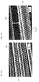
- FIG. 4A An SEM photograph of the CNTs 5, which was obtained by adding a small amount of the dispersion produced in the above described steps dropwise to a silicon substrate and then drying it in an oven at 400°C for 1 hour, is shown in FIG. 4A.
- FIG. 4B is an SEM photograph of the CNTs 110 obtained by subjecting a dispersion containing common CNTs to the same treatments as those described above.
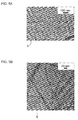
- the CNTs 5 are like individual nano-dispersed fibers with a high aspect ratio.
- FIG. 4B it is found that the CNTs 110 are inappropriate to be used in formation of a network structure because the aspect ratio thereof is low.
- FIG. 4B the portion indicated with the arrow indicates a state in which the CNTs 110 are not isolated from one another but aggregate.
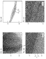
- FIG. 5A and FIG. 5B each show a TEM photograph of the CNTs 5 in the dispersion produced in the above described steps. As shown in FIG. 5A and FIG. 5B , all of the CNTs 5 have a tubular shape, and their diameters are almost 20 nm or less, and thus, it is found that the CNTs 5 have a shape suitable for formation of a uniform CNT network. To this dispersion, neither a dispersant nor an adhesive has been added.
- FIG. 6A to FIG. 6D each show an SEM photograph of the composite material 1 of the first embodiment.
- FIG. 6A shows a plurality of composite materials 1
- FIG. 6B to FIG. 6D show successive enlargements of the photograph of FIG. 6A .
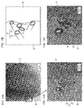
- the composite material 1 a state in which a plurality of CNTs 5 are uniformly dispersed on the surface of the base material 3 to form a structure 7 without intermediary agents is shown. Since the concentration of the CNTs 5 with respect to the base material 3 is low in this composite material 1, the surface of the base material 3 is directly exposed from the structure 7 without intermediary agents. It is apparent that the composite material 1 shown in FIG. 6A to 6D has the properties that have been explained with reference to FIG. 2A .
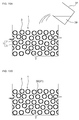
- FIG. 7A to FIG. 7C are SEM photographs showing successive enlargements of the section of the composite material of the first embodiment, and FIG. 7D is a view schematically showing FIG. 7C .
- FIG. 8A to FIG. 8C are TEM photographs showing successive enlargements of the section of the composite material of the first embodiment.
- the numbers 5a and 5b indicate CNTs
- the number 9 indicates an epoxy resin.
- CNTs 5a directly adhere to the surface of the base material 3 without intermediary agents, and the section thereof is shown.
- the other CNTs 5b form a network structure and are allowed to directly come into contact with or are directly connected with one another, and also the CNTs 5b directly adhere to the surface of the base material 3 without intermediary agents, and the section thereof is shown.
- FIG. 9A to FIG. 9C are TEM photographs showing successive enlargements of another portion of the section of the composite material of the first embodiment.
- CNTs 5 form a network structure and are allowed to directly come into contact with or are directly connected with one another without intermediary agents, and also the CNTs 5 directly adhere to the surface of the base material 3 without intermediary agents, and the section thereof is shown.
- FIG. 10A to FIG. 10C are other TEM photographs showing successive enlargements of a further portion of the section of the composite material of the first embodiment.
- CNTs 5 form a network with one another without intermediary agents and are allowed to directly come into contact with or are directly connected with one another, and also the CNTs 5 directly adhere to the surface of the base material 3 without intermediary agents, and the section thereof is shown.
- a plurality of CNTs 5 are uniformly dispersed on the surface of the base material 3, so as to configure a structure 7.
- No intermediary agents are observed in the periphery of each CNT 5, and the CNTs 5 are allowed to directly come into contact with or are directly connected with one another, and directly adhere to the surface of the base material 3, so as to configure the structure 7.
- a state in which each CNT 5 directly adheres to the surface of the base material 3 without intermediary agents is shown.
- the composite material 1 shown in each of FIG. 6A to FIG. 10D apparently has the properties explained with reference to FIG. 2A .
- a conventional composite material 120 produced using a dispersant as an intermediary agent is produced by putting carbon fibers used as a base material in a dispersion of CNTs 5, into which a dispersant and an adhesive have been added, and the surface of the carbon fibers is coated with a structure 7, the dispersant and the adhesive, and is thus hardly exposed.
- the plurality of CNTs 5 are complicatedly dispersed in the dispersion to form the structure 7. Since the surface of the CNTs 5 is coated with the dispersant or the adhesive, the CNTs 5 adhere to the surface of the carbon fibers mediated by the dispersant or the adhesive. Accordingly, the conventional composite material 120 shown in FIG. 11A and FIG. 11B apparently does not comprise the properties explained with reference to FIG. 2A .
- FIG. 12 is a view showing the properties of conductivity of each of a material consisting only of carbon fibers, the conventional composite material 120, and the composite material 1 of the first embodiment.
- CNTs 5 adhere to the surface of carbon fibers via a surfactant that is a dispersant.
- CNTs 5 directly adhere to the surface of carbon fibers without using a surfactant as an intermediary agent.
- the horizontal axis indicates the density of carbon fibers (g/cm 3 ), and the longitudinal axis indicates volume resistivity ( ⁇ ⁇ cm). The volume resistivity ( ⁇ ⁇ cm) was measured using Powder Resistivity Measurement System (manufactured by Mitsubishi Chemical Analytech Co., Ltd., product name: MCP-PD51).
- characteristic line A1 indicates the properties of the material consisting only of carbon fibers
- characteristic line A2 indicates the properties of the conventional composite material 120.
- This conventional composite material 120 contains CNTs 5 at a concentration of 0.1 wt % with respect to the carbon fibers, and at the same time, a surfactant is present as an intermediary agent in the conventional composite material 120.
- Characteristic line A3 indicates the properties of the composite material 1 of the first embodiment.
- This composite material 1 of the first embodiment contains CNTs 5 at a concentration of 0.05 wt % with respect to the carbon fibers used as a base material 3, and at the same time, a surfactant is not present as an intermediary agent in the composite material 1 of the first embodiment.
- the volume resistivity of the material consisting only of carbon fibers indicated as characteristic line A1 is 0.0110 ( ⁇ ⁇ cm)
- the volume resistivity of the conventional composite material 120 indicated as characteristic line A2 is 0.0111 ( ⁇ ⁇ cm)
- the volume resistivity of the composite material 1 of the first embodiment indicated as characteristic line A3 is 0.0098 ( ⁇ ⁇ cm) . From these results, it is found that the composite material 1 of the first embodiment has the best conductivity.
- the obtained conductivity is the conductivity of the carbon fibers themselves, the ratio in which the carbon fibers are allowed to directly come into contact with one another is low, and the conductivity is totally low.
- the characteristic line A2 even if the contact or connection is mediated by the structure 7, since a surfactant is present as an intermediary agent on the surface of CNTs constituting the structure 7, such an intermediary agent becomes resistance upon the contact or connection among the CNTs in the structure 7 or the contact or connection of the structure 7 with the surface of carbon fibers.
- the conductivity of the characteristic line A2 is rather slightly lower than the conductivity of the characteristic line A1, and thus, it has not arrived at a required level for practical use.
- CNTs 5 are allowed to directly come into contact with or are directly connected with one another without using a surfactant that is an intermediary agent, and further, the CNTs 5 are almost uniformly dispersed and intertwine to directly come into contact or to be directly connected on the surface of carbon fibers without surfactants serving as intermediary agents.
- the conductivity thereof has been improved by 10% or more.
- a conventional composite material which comprises CNTs at a concentration of over 10 wt % with respect to carbon fibers and in which a surfactant is present as an intermediary agent, has conductivity poorer than that of the composite material 1 of the first embodiment.
- FIG. 13 is a view showing the properties of heat conductivity of each of a material consisting only of carbon fibers, the conventional composite material 120, and the composite material 1 of the first embodiment.
- the conventional composite material 120 has CNTs adhered to the surface of carbon fibers via a surfactant that is an intermediary agent.
- the composite material 1 of the first embodiment has CNTs directly adhered to the surface of carbon fibers without using a surfactant as an intermediary agent.
- B1 indicates the heat conductive properties of the material consisting only of carbon fibers
- B2 indicates the heat conductive properties of the conventional composite material 120
- B3 indicates the heat conductive properties of the composite material 1 of the first embodiment.
- the longitudinal axis indicates temperature (°C).
- heat conductive properties were measured according to the following procedures.
- the material consisting only of carbon fibers, the conventional composite material 120, and the composite material 1 of the first embodiment were each fixed with an epoxy resin, so that samples each having a length of 1.5 cm and a diameter of 1.7 mm were prepared.
- the heat conductive properties of each sample were measured individually.
- the samples were each connected with a contact thermometer (manufactured by Anritsu Meter Co., Ltd., product name: HA-100), and thereafter, the samples were each placed on a hot plate with a size of 180 x 180 mm in height and width that consisted of a ceramic material (manufactured by TGK Station, product name: Hotplate Chimarec HP131224).
- the temperature of this hot plate was set at 85(°C), and the individual samples were heated from a single ordinary temperature by the fever of the hot plate for 2 minutes. The temperature of each sample was increased by the transfer of the fever of the hot plate. The increased temperature was measured using the contact thermometer.
- the temperature of the material consisting only of carbon fibers was measured to be approximately 68(°C) as shown in B1
- the temperature of the conventional composite material 120 was measured to be approximately 66.6(°C) as shown in B2.
- the temperature of the composite material 1 of the first embodiment was measured to be approximately 71.2(°C).
- the composite material of the first embodiment since a plurality of CNTs are allowed to directly come into contact with or are directly connected with one another's CNT surfaces without intermediary agents, and they are dispersed and intertwine with one another on the surface of the base material so as to configure a CNT network, even if small quantities of CNTs are used, the composite material of the first embodiment can exhibit electrical conductivity and heat conductivity, which are higher than those of the conventional composite material.
- the composite material of the first embodiment is a composite material with improved mechanical strength, in comparison to the conventional composite material.
- CNTs adhere to carbon fibers used as a base material at a low concentration of 0.001 to 20 wt %, preferably 0.01 to 10 wt %, and more preferably 0.01 to 5 wt %. That is to say, it can be said that the composite material of the first embodiment is a composite material that can exhibit performance, namely, conductivity and heat conductivity, which are higher than those of the conventional composite material, although the amount of CNTs is small.
- FIG. 14 is a conceptual configuration diagram of a molded article 20, in which the composite material 1 of the first embodiment is used.
- the molded article 20 comprises a matrix material 21 and a composite material 1 dispersed in the matrix material 21.
- a resin for example, an epoxy resin, can be used.
- the matrix material 21 is not limited to the epoxy resin, and examples of the matrix material 21 include thermosetting resins such as a phenolic resin, a melamine resin, a urea resin, an unsaturated polyester resin, an alkyd resin and thermosetting polyimide, thermoplastic resins such as polyethylene, polypropylene, polystyrene, an acrylonitrile/styrene resin, an acrylonitrile/butadiene/styrene resin, a methacrylic resin and vinyl chloride, engineering plastics such as polyamide, polyacetal, polyethylene terephthalate, ultrahigh molecular weight polyethylene and polycarbonate, and super engineering plastics such as polyphenylene sulfide, polyether ether ketone, a liquid crystal polymer, polytetrafluoroethylene, polyether imide, polyarylate and polyimide.
- thermosetting resins such as a phenolic resin, a melamine resin, a urea resin, an unsaturated polyester resin
- the matrix material 21 may comprise inorganic materials including metals such as aluminum, copper, titanium or silicon, or the oxides thereof, as well as a resin.
- a dispersant in order to uniformly disperse the composite material 1 in the matrix material 21, a dispersant, an adhesive, and other additives may be used.
- dispersant serving as an intermediary agent examples include an amphoteric surfactant, an anionic surfactant, a cationic surfactant, and a nonionic surfactant.
- amphoteric surfactant examples include sulfobetaines, phosphobetaines, carboxybetaines, imidazolium betaines, and alkylamine oxides.
- anionic surfactant examples include alkylbenzene sulfonate (e.g., C6-24 alkylbenzene sulfonate such as sodium laurylbenzenesulfonate, etc.), alkylnaphthalene sulfonate (e.g., di-C3-8 alkylnaphthalene sulfonate such as sodium diisopropylnaphthalenesulfonate, etc.), alkyl sulfonate (e.g., C6-24 alkyl sulfonate such as sodium dodecanesulfonate, etc.), dialkylsulfosuccinic acid ester salt (e.g., di-C6-24 alkyl sulfosuccinate such as sodium di-2-ethylhexylsulfosuccinate, etc.), alkyl sulfate (e.g., sulfated grease, C6-24 alkyl s
- cationic surfactant examples include tetraalkylammonium salt (e.g., mono- or di-C8-24 alkyl-tri- or di-methylammonium salts such as lauryltrimethylammonium chloride or dioctadecyldimethylammonium chloride, etc.), trialkylbenzylammonium salt [e.g., C8-24 alkylbenzyldimethylammonium salt such as cetylbenzyldimethylammonium chloride (benzalkonium chloride salt, etc.), etc.], and alkylpyridinium salt (e.g., C8-24 alkylpyridinium salt such as cetylpyridinium bromide, etc.).
- tetraalkylammonium salt e.g., mono- or di-C8-24 alkyl-tri- or di-methylammonium salts such as lauryltrimethylammonium chloride or dioctadecyldimethyl
- nonionic surfactant examples include polyoxyethylene alkyl ether (e.g., polyoxyethylene C6-24 alkyl ether such as polyoxyethylene octyl ether, polyoxyethylene lauryl ether or polyoxyethylene cetyl ether), polyoxyethylene alkylphenyl ether (e.g., polyoxyethylene C6-18 alkylphenyl ether such as polyoxyethylene octylphenyl ether or polyoxyethylene nonylphenyl ether, etc.), polyoxyethylene polyhydric alcohol fatty acid partial ester (e.g., polyoxyethylene glycerin C8-24 fatty acid ester such as polyoxyethylene glycerin stearic acid ester, polyoxyethylene sorbitan C8-24 fatty acid ester such as polyoxyethylene sorbitan stearic acid ester, polyoxyethylene sucrose C8-24 fatty acid ester, etc.), and polyglycerin fatty acid ester (e.g., polyglycerin C6
- examples of the adhesive serving as an intermediary agent include adhesive resins such as a polyolefin resin, an acrylic resin, a vinyl acetate resin, a polyester resin, a polyamide resin, and a polyurethane resin.
- examples of the additive include surface treatment agents (coupling agents such as a silane coupling agent, etc.), coloring agents (dyes and pigments, etc.), hue improving agents, dye fixing agents, glossing agents, metal corrosion preventing agents, stabilizers (an antioxidant, an ultraviolet absorber, etc.), dispersion stabilizing agents, thickeners or viscosity adjusting agents, thixotropic property-imparting agents, leveling agents, defoaming agents, disinfectants, and fillers.
- surface treatment agents such as a silane coupling agent, etc.
- coloring agents dye fixing agents
- glossing agents glossing agents
- metal corrosion preventing agents stabilizers (an antioxidant, an ultraviolet absorber, etc.)
- dispersion stabilizing agents thickeners or viscosity adjusting agents, thixotropic property-imparting agents, leveling agents, defoaming agents, disinfectants, and fillers.
- FIG. 15A from a beaker 37, an epoxy resin 39 is added into a composite material 1.
- the epoxy resin 39 incorporated into the composite material 1 strongly adhere to the composite material 1, as shown in FIG. 15B . Accordingly, in the molded article 20, the composite material 1 can be prevented from being removed from the surface of the matrix material 21 (epoxy resin 39).
- FIG. 16A and FIG. 16B are views showing conventional methods for producing a fiber-reinforced molded article.
- a solution containing the epoxy resin 39 that is a matrix material and CNTs 5 is added into the base materials 3.
- the CNTs 5 are captured by the upper portion of the base materials 3 during filtration, and the CNTs 5 are not present in the lower portion thereof.
- the epoxy resin 39 that impregnated the lower portion of the base materials 3 is allowed to directly come into contact with the base materials 3. Accordingly, the conventional molded article has a structure in which the base materials 3 are easily removed from the surface of the matrix material (epoxy resin 39).
- a plurality of base materials 3 are dispersed in the matrix material 21, and a structure 7 formed from a plurality of CNTs 5 is formed on the surface of the base materials 3.
- the base materials 3 strongly adhere to the matrix material 21 due to the CNTs 5 constituting the structure 7.
- the debonding strength between the composite material 1 and the matrix material 21 is improved.
- the concentration of the CNTs 5 constituting the structure 7 is low, the characteristics of the matrix material 21, such as flexibility, are not canceled. Therefore, since the molded article 20 comprises the composite material 1, while the molded article 20 effectively takes advantage of the characteristics of the matrix material 21, such as flexibility and other properties, it can also enhance mechanical strength.
- the composite material 1 is configured such that the structure 7 has previously adhered to the surface of the base material 3, by impregnating the composite material 1 with a resin that is the matrix material 21, the effect of fiber reinforcement can be obtained throughout the entire molded article 20.
- the structure 7 is sufficiently impregnated with a resin that is the matrix material 21. Therefore, the occurrence of debonding between the composite materials 1 and the matrix material 21 can be prevented.
- the present invention is not limited to the above described embodiments.
- the present invention can be appropriately modified in the range of the gist thereof.
- the film thickness of the structure 7 is preferably 500 nm or less in the case of the first embodiment.
- the present invention is not limited thereto.
- a modification example of the structure 7 will be described.
- the content of the base material 3 is increased, the total amount of CNTs 5 adhered can be increased, and upon production of the molded article 20, it is also possible to narrow the separation distance between the adjacent base materials 3 by the combined use of a high-pressure press molding production method.
- a molded article 30 comprises a matrix material 21, and a composite material 31 dispersed in the matrix material 21.
- the composite material 31 according to the present modification example is different from that of the above described first embodiment, in that the content of CNTs 5 to the base materials 3 is larger than that of the first embodiment.
- the composite material 31 has a structure 32 having a film thickness (t) of more than 500 nm.
- connections 33 that are crosslinked are formed in some portions between the adjacent base materials 3. From the connection 33, a further effect of improving the strength of the base material 3 can be obtained. Hereafter, this effect will be described more in detail.
- One factor for reducing the strength of a fiber-reinforced molded article comprising the composite material 1 is low adhesion strength obtained between the base material 3 and the matrix material 21.
- portions in which the matrix material 21 is removed from the base material 3 are found.
- a connection 33 that is crosslinked is formed, since the connection 33 plays a role for connecting the adjacent base materials 3 with each other, the debonding of the base materials 3 or cracking can be prevented.
- breaking strength and toughness as typical examples, are improved.
- the film thickness (t) is not set at an amount in which the connection 33 is protruded from the surface of the base material 3, but the mean value of the thickness from one surface of the connection 33 that is crosslinked to the other surface can be defined as a film thickness (t), as shown in FIG. 17B .
- the film thickness (t) in such a case becomes 500 nm or less, as with the amount in which the connection 33 is protruded from the surface of the base material 3.
- the amount in which the connection 33 is protruded from the surface of the base material 3 becomes identical to the thickness from one surface of the connection 33 crosslinked to the other surface for the following reason.
- the CNTs 5 used in the present modification example are in an isolated dispersion state, the CNTs 5 closely adhere to the surface of the base material 3 to form the structure 32.
- the film thickness (t) of the structure 32 consisting of the CNTs 5 closely adhering to the surface of the base material 3 becomes identical to the thickness from one surface of the connection 33 protruded from the surface of the base material 3 to the other surface.
- the adhesiveness between the base material 3 and the structure 32 can be reinforced by adopting this configuration. This reinforcing effect significantly appears, when a treatment for improving the adhesiveness between the surface of the structure 32 and the base material, etc. is carried out.
- the network length is not particularly limited at this time.
- some of the structures 32 are peeled from the surface of the base material 3 and float in the matrix material 21.
- the thus floating structures 32 move with the flow of the resin in a press molding step upon production of a molded article, and are then filled in the voids of the base materials 3, so that they newly form a structure of crosslinking the base materials 3 and they function to improve the strength of the molded article 30.
- the occupancy of the base materials 3 per unit cross-sectional area in the molded article 30 is set at 30% or more. If the occupancy of the base materials 3 is less than 30%, the separation distance between the adjacent base materials 3 becomes several tens of ⁇ m or more, and as a result, the separation distance between the base materials 3 is too far, and the connection 33 that is crosslinked is hardly formed. In contrast, if the occupancy of the base materials 3 is 30% or more, the separation distance between the adjacent base materials 3 becomes 10 ⁇ m or less, and it becomes easy to form the connection 33 that is crosslinked. Hereafter, this will be described more in detail.
- the occupancy of the base materials 3 is in the range of 30% or more and less than 50%, the separation distance between the base materials 3 becomes 3 to 10 ⁇ m, and the connection 33 that is crosslinked can be easily obtained.
- the occupancy of the base materials 3 is 50% to 70%, the separation distance between the base materials 3 becomes 1 to 3 ⁇ m, and the connection 33 that is crosslinked can be more easily obtained.
- the occupancy of the base materials 3 is in the range exceeding 70% up to the upper limit of packing of the base materials 3 (in a closely packed state)
- the connections 33 that is crosslinked are filled at a high density in the voids of the base materials 3, together with the flow of the resin upon molding, and the structure 32 coated on the surface of the base materials 3 is integrated with the matrix material 21.
- the strength-improving effect by the connection 33 that is crosslinked is maximized. It is to be noted that such a highly filled state of the base materials 3 can be realized, for example, by high-pressure pressing using a pressing machine or the like.
- the above described occupancy of the base materials 3 per unit cross-sectional area in the molded article 30 can be calculated, for example, as follows. Specifically, the fracture surface of the molded article 30 comprising the composite material 1 is observed under an electron microscope such as SEM. In a case where the base material 3 is a short fiber, the direction of the base materials 3 in the molded article 30 becomes random. As such, a visual field in which at least 10 sections of the base materials 3 seem to be closely present in the observed region is extracted, and the occupancy of the base materials 3 per unit cross-sectional area in the extracted visual field is calculated by measurement.
- the method for producing the molded article 30 also includes a production method comprising pouring the composite material 31, in which the epoxy resin 39 is filled, into a mold, and then pressing it with a high pressure to mold the molded article 30 of the present invention.
- a production method comprising pouring the composite material 31, in which the epoxy resin 39 is filled, into a mold, and then pressing it with a high pressure to mold the molded article 30 of the present invention.
- the base material 3 is a fiber
- the present invention is not limited to this case, and for example, a product having a particle form, such as activated carbon, is also included in the present invention.
Landscapes
- Chemical & Material Sciences (AREA)
- Engineering & Computer Science (AREA)
- Materials Engineering (AREA)
- Nanotechnology (AREA)
- Chemical Kinetics & Catalysis (AREA)
- Organic Chemistry (AREA)
- Health & Medical Sciences (AREA)
- Polymers & Plastics (AREA)
- Manufacturing & Machinery (AREA)
- Medicinal Chemistry (AREA)
- Textile Engineering (AREA)
- Inorganic Chemistry (AREA)
- Composite Materials (AREA)
- Condensed Matter Physics & Semiconductors (AREA)
- General Physics & Mathematics (AREA)
- Crystallography & Structural Chemistry (AREA)
- Physics & Mathematics (AREA)
- Carbon And Carbon Compounds (AREA)
- Compositions Of Macromolecular Compounds (AREA)
- Chemical Or Physical Treatment Of Fibers (AREA)
- General Chemical & Material Sciences (AREA)
- Laminated Bodies (AREA)
Abstract
Description
- The present invention relates to a composite material, in which carbon nanotubes (hereinafter abbreviated as "CNT") adhere to the surface of a base material, and a molded article comprising the composite material.
- In such a composite material, in order for the composite material to exhibit the functions as a composite material, it is desired that CNTs uniformly adhere to the surface of a base material, so as to form a CNT network.
- Such a composite material is produced by putting a base material in a solution in which CNTs are dispersed at a nano level (which is also abbreviated as a "CNT nano-dispersion" in the present description), allowing the CNTs to adhere to the surface of the base material while forming a network, then raising the base material from the CNT nano-dispersion, and then drying it.
- However, since such CNTs irreversibly aggregate in the CNT nano-dispersion due to the van der Waals force, in order to allow the CNTs to uniformly adhere to the surface of the base material to form a CNT network, it is necessary to add a large amount of dispersant into the CNT nano-dispersion, so that aggregation of the CNTs is prevented and the CNTs are dispersed therein.
- Moreover, upon this dispersion, ultrasonic irradiation or stirring is performed as an auxiliary treatment on the CNT nano-dispersion (see Patent Literature 1). A dispersant is required for dispersion of the CNTs, and in general, the dispersant has been used as an essential agent in the production process of the composite material.
- Furthermore, in addition to the dispersant, an adhesive and other additives are also added to the CNT nano-dispersion, in order to allow the CNTs to adhere to the surface of the base material.
- Since CNTs adhere to the base material in the thus produced composite material, it is expected that the composite material will exhibit the original functions of the base material, and will also exhibit improved electrical conductivity, heat conductivity, mechanical strength and the like, which are derived from the CNTs.
- Patent Literature 1: Japanese Patent Laid-Open No.
2010-59561 - In the above described composite material, in order to improve the performances as a composite material, such as electrical conductivity, heat conductivity and mechanical strength, CNTs have been allowed to adhere to the surface of a base material generally at a high concentration, and thereby a CNT network have been constructed at a high density on the surface of the base material.
- However, when large quantities of CNTs are used, there is a fear that the original functions of the base material may be impaired. Meanwhile, although large quantities of CNTs have been adhered to the surface of the base material, the electrical conductivity, heat conductivity, mechanical strength and the like of the composite material have not yet arrived at a request level for practical use under the current circumstances.
- It is an object of the present invention to provide a composite material capable of exhibiting the original functions of a base material thereof and also capable of exhibiting functions derived from CNTs, such as electrical conductivity, heat conductivity and mechanical strength, and a molded article therefrom.
- In order to solve the current problem that in spite of incorporation of large quantities of CNTs into the composite material, the electrical conductivity, heat conductivity, mechanical strength and the like of the composite material have not yet arrived at a request level for practical use, the inventors have conducted studies considering that the cause of the aforementioned problem would be that a dispersant for dispersing CNTs, an adhesive for allowing the CNTs to adhere to the base material, and the likes are coated on the surface of such CNTs, but they are intermediary agents causing insulation or heat conduction failure. However, since the CNTs themselves have aggregation force, such a dispersant and an adhesive acting as intermediary agents are essential for uniformly dispersing the CNTs on the surface of the base material and allowing them to adhere thereto, and thus, there is no choice but to use them.
- The present invention relates to a composite material, which maintains good dispersibility of CNTs even in a state in which there are no intermediary agents such as a dispersant and an adhesive essential for dispersion and adhesion of the CNTs, and which exhibits functions derived from CNTs, such as electrical conductivity, heat conductivity and mechanical strength, even in a low concentration of the CNTs, thereby satisfying a request level for practical use.
- That is to say, a composite material according to the present invention comprises a base material and a structure formed on the surface of the base material, wherein the structure includes a plurality of carbon nanotubes that form a network structure, in which the carbon nanotubes are directly connected with one another and also directly adhere to the surface of the base material.
- A molded article according to the present invention comprises a composite material of the present invention.
- A composite material according to the present invention is a composite material in which a plurality of CNTs adhere to the surface of a base material, and the present composite material is characterized in that it is configured by dispersing the plurality of CNTs in a solution that does not contain intermediary agents such as a dispersant, then giving predetermined energy to the solution to create a reversible reaction state, in which a state in which the plurality of CNTs are dispersed in the solution and a state in which the plurality of CNTs aggregate in the solution reversibly take place, and then, when the plurality of CNTs transfer from the dispersion state to the aggregation state, by allowing the plurality of CNTs that intertwine with one another in a network form to directly come into contact with one another or to be directly connected with one another without intermediary agents, so that the CNTs directly adhere to the surface of the base material immersed in the solution in the reversible reaction condition without intermediary agents.
- According to the composite material of the present invention, a plurality of CNTs are allowed to directly come into contact with, or to be directly connected with surfaces of the CNTs without intermediary agents, so that the plurality of CNTs are dispersed and intertwine with one another on the surface of a base material, thereby forming a CNT network. Accordingly, even if small quantities of CNTs are used, the composite material can exhibit the performance derived from the CNTs, such as electrical conductivity and heat conductivity. Moreover, since the plurality of CNTs form a CNT network and directly adhere to the surface of the base material in a state in which there are no intermediary agents, the CNTs are hardly removed from the surface of the base material, and the mechanical strength of the composite material is thereby improved.
- According to a molded article of the present invention, since the molded article comprises the composite material of the present invention, the mechanical strength thereof can be significantly improved, even if the base material of the molded article is, for example, a resin.
-
-
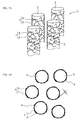
FIG. 1A is a conceptual configuration diagram of a composite material according to a first embodiment, andFIG. 1B is a view showing a thickness of a structure in the composite material of the embodiment; -
FIG. 2A is a conceptual configuration diagram of a composite material according to the first embodiment, andFIG. 2B is a conceptual configuration diagram of a conventional composite material; -
FIG. 3 is a production step view of the composite material of the first embodiment; -
FIG. 4 includes SEM (scanning electron microscope) photographs of CNTs taken after a small amount of dispersion containing the CNTs has been added dropwise onto a silicon substrate and it has been then dried in an oven at 400°C for 1 hour,FIG. 4A is a photograph of the CNTs according to the first embodiment, andFIG. 4B is a photograph of common CNTs; -
FIG. 5A is a TEM (transmission electron microscope) photograph of CNTs in a dispersion containing the CNTs according to the first embodiment, andFIG. 5B is an enlarged photograph ofFIG. 5A ; -
FIG. 6A is an SEM photograph of the appearance of the composite material of the first embodiment, andFIG. 6B is an enlarged photograph ofFIG. 6A, FIG. 6C is an enlarged photograph of another portion ofFIG. 6A, and FIG. 6D is a further enlarged photograph ofFIG. 6C ; -
FIGS. 7A-7D are SEM photographs showing successive enlargements of the section of the composite material of the first embodiment,FIG. 7A is an SEM photograph of the section of the composite material,FIG. 7B is an enlarged SEM photograph,FIG. 7C is a further enlarged SEM photograph, andFIG. 7D is a view schematically showingFIG. 7C . -
FIGS. 8A-8D are TEM photographs showing successive enlargements of the section of the composite material of the first embodiment,FIG. 8A is a TEM photograph of the section of the composite material, andFIG. 8B is a TEM photograph obtained by the enlargement of the portion enclosed with the square frame inFIG. 8A, FIG. 8C is a TEM photograph obtained by further enlargement of the portion enclosed with the square frame inFIG. 8B, and FIG. 8D is a view schematically showingFIG. 8B ; -
FIGS. 9A-9D are TEM photographs showing successive enlargements of the section of the composite material of the first embodiment,FIG. 9A is a TEM photograph of the section of the composite material, andFIG. 9B is a TEM photograph obtained by the enlargement of the portion enclosed with the square frame inFIG. 9A, FIG. 9C is a TEM photograph obtained by further enlargement of a portion inFIG. 9B, and FIG. 9D is a view schematically showingFIG. 9B ; -
FIGS. 10A-10D are TEM photographs showing successive enlargements of the section of the composite material of the first embodiment,FIG. 10A is a TEM photograph of the section of the composite material, andFIG. 10B is a TEM photograph obtained by the enlargement of the portion enclosed with the square frame inFIG. 10A, FIG. 10C is a TEM photograph obtained by further enlargement of a portion inFIG. 10B, and FIG. 10D is a view schematically showingFIG. 10B ; -
FIG. 11A is an SEM photograph of a conventional composite material, andFIG. 11B is an enlarged SEM photograph ofFIG. 11A ; -
FIG. 12 is a view showing the conductive properties of a composite material consisting only of carbon fibers, a conventional composite material, and the composite material of the first embodiment. -
FIG. 13 is a view showing the heat conductive properties of a composite material consisting only of carbon fibers, a conventional composite material, and the composite material of the first embodiment; -
FIG. 14 is a conceptual configuration diagram of the molded article of a second embodiment; -
FIG. 15A is a view showing a state in which an epoxy resin is added into a composite material in a method for producing the molded article of the second embodiment, andFIG. 15B is a view showing a condition in which an epoxy resin has been added into a composite material; -
FIG. 16A is a view showing a state in which a CNT composite epoxy resin is added into carbon fibers in a method for producing a conventional fiber-reinforced molded article, andFIG. 16B is a view showing a condition in which a CNT composite epoxy resin has been added into carbon fibers; -
FIG. 17A is a view showing a conceptual configuration of a composite material and a molded article as a modification example,FIG. 17B is a view showing a thickness of a structure from the surface of a base material; -
FIG. 18 is an SEM photograph of a composite material as a modification example; and -
FIG. 19 is a view showing a conceptual configuration of a composite material as another modification example. - Hereinafter, the embodiments of the present invention will be described in detail with reference to the drawings.
- As shown in
FIG. 1A , acomposite material 1 comprises a plurality ofbase materials 3 and astructure 7 formed on the surface of each of the plurality ofbase materials 3. - The
base material 3 is not particularly limited. Examples of thebase material 3 include fibers formed from carbon materials, resin materials, metal materials, ceramic materials, and the like. In the case of the present embodiment, a carbon fiber is applied as abase material 3. It is to be noted that, in the present figure, a plurality ofbase materials 3 are shown for illustrative purposes. Thebase material 3 is not particularly limited, and an example of thebase material 3 is a carbon fiber having a diameter of approximately 3 to 15 µm, which is obtained by calcination of organic fibers derived from petroleum, coal or coal tar, such as polyacrylonitrile, rayon or pitch, or organic fibers derived from timbers or plant fibers. - The
structure 7 comprises a plurality ofCNTs 5. TheCNTs 5 are uniformly dispersed on almost the entire surface of thebase material 3 and intertwine with one another, so that they are allowed to directly come into contact with or are directly connected with one another without intermediary agents and thereby form a network structure, and at the same time, theCNTs 5 directly adhere to the surface of thebase material 3, in a state in which there are no intermediary agents at the boundary with the surface of thebase material 3. The term "connect" is used herein to include a physical connection (simple contact). In addition, the term "adhere" is used herein to mean a bond due to the van der Waals force. Moreover, the expression "are allowed to directly come into contact with or are directly connected with" is used herein to include not only a state in which a plurality of CNTs are allowed to simply come into contact with one another without intermediary agents, but also a state in which the plurality of CNTs are connected with one another in an integrated manner. Thus, this expression should not be interpreted in such a limitation. - The
structure 7 is locally unevenly distributed on the surface of thebase material 3. Due to such an uneven distribution, the surface of thebase material 3 is exposed from thestructure 7. This "uneven distribution" merely indicates that the entire surface of thebase material 3 is not uniformly coated with thestructure 7, and this does not indicate the quality of the dispersibility of theCNTs 5 in thestructure 7 itself. - The
structure 7 can be referred to as a CNT network because theCNTs 5 are distributed on the surface of thebase material 3 in a network form. Also, since the entire network constitutes a thin film, it is referred to as a CNT network, and thus, the name is not intended to limit the meanings. - Moreover, it may be adequate even if the
CNTs 5 do not form a single network structure on the entire surface of thebase material 3, or it may also be adequate even if a plurality of network structures that are independent from one another are present with respect to the single surface of thebase material 3. Otherwise, it may also be adequate even if thestructure 7 is not present on the entire single surface of thebase material 3, or thestructure 7 may be partially formed thereon. - As shown in
FIG. 1B , thestructure 7 forms a thin film, seeing from the section of thecomposite material 1, and the film thickness (t) is not limited. For example, the thickness of the thin film is preferably 500 nm or less. Thestructure 7 can exhibit its functions effectively, as long as the film thickness (t) is 500 nm or less from the surface of thebase material 3. Naturally, the film thickness (t) of thestructure 7 may also be more than 500 nm. - The film thickness (t) of the
structure 7 from the surface of thebase material 3 is measured as follows. Specifically, any material bundle is sampled from the CNT/carbonfiber composite material 1, and it is fixed on a metallic sample stand using a conductive tape or the like. From the sampled material bundle, a part of thebase material 3 is debonded, and thestructure 7 is exposed from the debonded site. Hence, the mean value (t) of the thickness of the section of the thus exposedstructure 7 is measured by observing it under a scanning electron microscope (SEM). - Furthermore, the film thickness (t) of the
structure 7 is more preferably 15 nm to 100 nm. If the thickness of thestructure 7 is in the above described range, theCNTs 5 are dispersed on the surface of thebase material 3, and they are directly connected with one another, so that a good network structure can be formed. - The length of the
CNT 5 that forms thestructure 7 is preferably 0.1 to 50 µm. If the length of theCNT 5 is 0.1 µm or more, theCNTs 5 intertwine with one another and are directly connected with one another. If the length of theCNT 5 is 50 µm or less, it becomes easy for theCNTs 5 to be uniformly dispersed. On the other hand, if the length of theCNT 5 is less than 0.1 µm, theCNTs 5 hardly intertwine with one another. If the length of theCNT 5 exceeds 50 µm, theCNTs 5 easily aggregate. - The
CNT 5 preferably has a mean diameter of approximately 30 nm or less. If the diameter of theCNT 5 is 30 nm or less, it is highly flexible and becomes deformed along the curvature of the surface of thebase material 3, so that a network structure can be formed. On the other hand, if the diameter of theCNT 5 exceeds 30 nm, flexibility is lost and it hardly becomes deformed along the surface of thebase material 3, so that a network structure can be hardly formed. It is to be noted that the diameter of theCNT 5 is defined as a mean diameter measured using a transmission electron microscope (TEM) photograph. TheCNT 5 more preferably has a mean diameter of approximately 20 nm or less. - The plurality of
CNTs 5 preferably adhere to the surface of thebase material 3 at a concentration of 0.001 to 20 wt % with respect to thebase material 3. When theCNTs 5 are in the above described concentration range, a portion that is not coated with theCNTs 5 is formed on the surface of thebase material 3. This portion that is not coated with theCNTs 5 is not coated with an adhesive or the like, and the surface of thebase material 3 is exposed therefrom. Thereby, the functions of thebase material 3 are not impaired by theCNTs 5. The concentration of theCNTs 5 is preferably 0.01 to 10 wt %, and more preferably 0.01 to 5 wt %, with respect to thebase material 3. - Moreover, as shown in
FIG. 2A , theCNTs 5 directly adhere to the surface of thebase material 3. That is to say, between theCNTs 5 and the surface of thebase material 3, there are no intermediary agents including a dispersant such as a surfactant, and an adhesive, and theCNTs 5 directly adhere to the surface of thebase material 3. - Next, a method for producing a
composite material 1 will be described. As shown inFIG. 3 , thecomposite material 1 can be produced by preparingCNTs 5 in step SP1, then preparing a dispersion containing theCNTs 5 in step SP2, and then forming astructure 7 on the surface of abase material 3 using the dispersion in step SP3. Hereafter, individual steps will be successively explained. -
CNTs 5, which are produced by forming a catalytic film consisting of aluminum and iron on a silicon substrate according to the thermal CVD method as described, for example, in Japanese Patent Laid-Open No.2007-126311 - The CNT may be either mono-walled or multi-walled. It is preferably a multi-walled CNT.
- Thereafter, using the produced
CNTs 5, a dispersion, in which theCNTs 5 are nano-dispersed, is produced. Nano-dispersion means a condition, in whichCNTs 5 are physically separated into individual nanotubes and are dispersed in a solution in a state in which they do not intertwine with one another, and also in which the percentage of aggregates in which two or more CNTs 5 are aggregated in a bundle form is 10% or less. - The dispersion is formed by adding the above
prepared CNTs 5 into a solvent, and then homogenizing the dispersion of theCNTs 5 using a homogenizer, shearing, an ultrasonic dispersant, etc. Examples of the solvent that can be used herein include water, alcohols such as ethanol, methanol or isopropyl alcohol, and organic solvents such as toluene, acetone, THF, MEK, hexane, normal hexane, ethyl ether, xylene, methyl acetate or ethyl acetate. The dispersion may contain a dispersant, a surfactant, an adhesive, an additive, etc., as long as it does not restrict the functions of thebase material 3 and theCNTs 5. - In step SP3, in a state in which the
base material 3 is immersed in the dispersion produced in the step SP2, mechanical energy such as shearing or ultrasonic wave is given to the dispersion, and thestructure 7, namely, a network structure of theCNTs 5 is unevenly formed on the surface of thebase material 3. - By giving mechanical energy to the dispersion, a reversible reaction condition, in which a state in which the
CNTs 5 are dispersed in the dispersion and a state in which theCNTs 5 aggregate therein are constantly generated, is created. - The
base material 3 is immersed in the dispersion that is in this reversible reaction condition. As a result, such a reversible reaction condition consisting of the dispersion state of theCNTs 5 and the aggregation state thereof takes place even on the surface of thebase material 3, and when theCNTs 5 transfer from the dispersion state to the aggregation state, theCNTs 5 adhere to the surface of thebase material 3. - Upon aggregation, the van der Waals force acts on the
CNTs 5, and theCNTs 5 adhere to the surface of thebase material 3 due to this van der Waals force. Thereafter, thebase material 3 is drawn from the dispersion and is then dried, so as to obtain thecomposite material 1, in which network structures are unevenly distributed on the surface of thebase material 3. - As shown in
FIG. 2A , in thecomposite material 1 of the present embodiment, theCNTs 5 are allowed to directly come into contact with or are directly connected with one another, and at the same time, theCNTs 5 form thestructure 7, and thestructure 7 directly adheres to the surface of thebase material 3. In thecomposite material 1 of the present embodiment, since theCNTs 5 are allowed to directly come into contact with or are directly connected with one another without intermediary agents, electrical conductivity and heat conductivity among theCNTs 5 in thestructure 7 are both high, and at the same time, since theCNTs 5 form thestructure 7 and the structure to the surface of thebase material 3 in a state in which there are no intermediary agents, the CNTs are hardly removed from the surface of thebase material 3, having high mechanical strength. - If the
base material 3 is a carbon fiber, the carbon fiber itself has conductivity. However, theCNT 5 has higher conductivity than the carbon fiber does. Thus, by forming thestructure 7 on the surface of carbon fibers without intermediary agents, the conductivity of thecomposite material 1 is significantly improved. Moreover, since the heat conductivity of theCNTs 5 is also extremely high, by forming thestructure 7 on the surface of carbon fibers without intermediary agents, the heat conductivity of thecomposite material 1 is also significantly improved. - Moreover, in the
composite material 1 of the present embodiment, by forming thestructure 7 on the surface of carbon fibers without intermediary agents, mechanical strength is significantly improved in comparison with carbon fibers alone. This is similar to a structure in which reinforcing steel surrounds a steel frame in a network form, so that the strength of a reinforced concrete can be increased. In this case, the carbon fiber plays a role as a steel frame, and the CNT plays a role as a reinforcing steel, and the resin plays a role as a concrete, respectively. - In contrast, as shown in
FIG. 2B , in a conventionalcomposite material 100, anintermediary agent 102 is present on the surface ofCNTs 101. Hence, theCNTs 101 are allowed to come into contact with or are connected with one another via theintermediary agent 102, and at the same time, theCNTs 101 form astructure 103, and this structure adheres to the surface of thebase material 3 via theintermediary agent 102. Examples of theintermediary agent 102 include dispersants such as a surfactant, products having an insulation property such as adhesive, and products having insufficient heat conductivity. In the conventionalcomposite material 100, since theCNTs 101 are allowed to come into contact with or are connected with one another via theintermediary agent 102, the electrical conductivity and heat conductivity between thestructures 103 are insufficient. Moreover, since theCNTs 101 constitute astructure 7 and the structure adheres to the surface of thebase material 3 via theintermediary agent 102, theCNTs 101 are easily removed from the surface of thebase material 3, and the mechanical strength thereof is low. - A
composite material 1 was produced according to the procedures described in the above described production method. AsCNT 5, MW-CNT (Multi-walled Carbon Nanotubes) that had been allowed to grow to a diameter of 10 to 15 nm and a length of 100 µm or more on a silicon substrate according to the thermal CVD method was used. In order to remove a catalytic residue from theCNT 5, a mixed acid of sulfuric acid and nitric acid (3 : 1) was used, and after completion of washing, it was filtrated and then dried. In order to cut theCNT 5, it was crushed with an ultrasonic homogenizer in a dispersion solvent, resulting in a length of 0.5 to 10 µm. Using methyl ethyl ketone as a dispersion solvent for the CNT, a dispersion was prepared. The concentration of theCNTs 5 in the dispersion was 0.01 wt %. - The prepared dispersion was observed under SEM and TEM. An SEM photograph of the
CNTs 5, which was obtained by adding a small amount of the dispersion produced in the above described steps dropwise to a silicon substrate and then drying it in an oven at 400°C for 1 hour, is shown inFIG. 4A. FIG. 4B is an SEM photograph of theCNTs 110 obtained by subjecting a dispersion containing common CNTs to the same treatments as those described above. As is apparent fromFIG. 4A , it is found that theCNTs 5 are like individual nano-dispersed fibers with a high aspect ratio. In contrast, as is apparent fromFIG. 4B , it is found that theCNTs 110 are inappropriate to be used in formation of a network structure because the aspect ratio thereof is low. Moreover, inFIG. 4B , the portion indicated with the arrow indicates a state in which theCNTs 110 are not isolated from one another but aggregate.FIG. 5A and FIG. 5B each show a TEM photograph of theCNTs 5 in the dispersion produced in the above described steps. As shown inFIG. 5A and FIG. 5B , all of theCNTs 5 have a tubular shape, and their diameters are almost 20 nm or less, and thus, it is found that theCNTs 5 have a shape suitable for formation of a uniform CNT network. To this dispersion, neither a dispersant nor an adhesive has been added. - Subsequently, while ultrasonic waves of 28 kHz and 40 kHz were given to the dispersion, carbon fibers (PAN carbon fibers, fiber diameter: 7 µm) were put as a
base material 3 in the dispersion, and the dispersion was then retained for 10 seconds. Thereafter, thebase material 3 was taken from the dispersion, and was then dried on a hot plate at approximately 80°C, so as to form astructure 7 on the surface of thebase material 3. Thus, thecomposite material 1 was obtained. -
FIG. 6A to FIG. 6D each show an SEM photograph of thecomposite material 1 of the first embodiment.FIG. 6A shows a plurality ofcomposite materials 1, andFIG. 6B to FIG. 6D show successive enlargements of the photograph ofFIG. 6A . With regard to thecomposite material 1, a state in which a plurality ofCNTs 5 are uniformly dispersed on the surface of thebase material 3 to form astructure 7 without intermediary agents is shown. Since the concentration of theCNTs 5 with respect to thebase material 3 is low in thiscomposite material 1, the surface of thebase material 3 is directly exposed from thestructure 7 without intermediary agents. It is apparent that thecomposite material 1 shown inFIG. 6A to 6D has the properties that have been explained with reference toFIG. 2A . -
FIG. 7A to FIG. 7C are SEM photographs showing successive enlargements of the section of the composite material of the first embodiment, andFIG. 7D is a view schematically showingFIG. 7C . -
FIG. 8A to FIG. 8C are TEM photographs showing successive enlargements of the section of the composite material of the first embodiment. In these figures, thenumbers number 9 indicates an epoxy resin. InFIG. 8A to FIG. 8C ,CNTs 5a directly adhere to the surface of thebase material 3 without intermediary agents, and the section thereof is shown. Theother CNTs 5b form a network structure and are allowed to directly come into contact with or are directly connected with one another, and also theCNTs 5b directly adhere to the surface of thebase material 3 without intermediary agents, and the section thereof is shown. -
FIG. 9A to FIG. 9C are TEM photographs showing successive enlargements of another portion of the section of the composite material of the first embodiment. InFIG. 9A to FIG. 9C ,CNTs 5 form a network structure and are allowed to directly come into contact with or are directly connected with one another without intermediary agents, and also theCNTs 5 directly adhere to the surface of thebase material 3 without intermediary agents, and the section thereof is shown. -
FIG. 10A to FIG. 10C are other TEM photographs showing successive enlargements of a further portion of the section of the composite material of the first embodiment. InFIG. 10A to FIG. 10C ,CNTs 5 form a network with one another without intermediary agents and are allowed to directly come into contact with or are directly connected with one another, and also theCNTs 5 directly adhere to the surface of thebase material 3 without intermediary agents, and the section thereof is shown. - As shown in the SEM photographs, TEM photographs and schematic views of
FIG. 6A to FIG. 10D , in thecomposite material 1 of the first embodiment, a plurality of CNTs 5 (5a and 5b) are uniformly dispersed on the surface of thebase material 3, so as to configure astructure 7. No intermediary agents are observed in the periphery of eachCNT 5, and theCNTs 5 are allowed to directly come into contact with or are directly connected with one another, and directly adhere to the surface of thebase material 3, so as to configure thestructure 7. In addition, a state in which eachCNT 5 directly adheres to the surface of thebase material 3 without intermediary agents is shown. In thiscomposite material 1, since the concentration of theCNTs 5 with respect to thebase material 3 is low, the surface of thebase material 3 is directly exposed from thestructure 7 without intermediary agents. Thecomposite material 1 shown in each ofFIG. 6A to FIG. 10D apparently has the properties explained with reference toFIG. 2A . - In contrast, as shown in
FIG. 11A and FIG. 11B , a conventionalcomposite material 120 produced using a dispersant as an intermediary agent is produced by putting carbon fibers used as a base material in a dispersion ofCNTs 5, into which a dispersant and an adhesive have been added, and the surface of the carbon fibers is coated with astructure 7, the dispersant and the adhesive, and is thus hardly exposed. The plurality ofCNTs 5 are complicatedly dispersed in the dispersion to form thestructure 7. Since the surface of theCNTs 5 is coated with the dispersant or the adhesive, theCNTs 5 adhere to the surface of the carbon fibers mediated by the dispersant or the adhesive. Accordingly, the conventionalcomposite material 120 shown inFIG. 11A and FIG. 11B apparently does not comprise the properties explained with reference toFIG. 2A . -
FIG. 12 is a view showing the properties of conductivity of each of a material consisting only of carbon fibers, the conventionalcomposite material 120, and thecomposite material 1 of the first embodiment. In the conventionalcomposite material 120,CNTs 5 adhere to the surface of carbon fibers via a surfactant that is a dispersant. In thecomposite material 1 of the first embodiment,CNTs 5 directly adhere to the surface of carbon fibers without using a surfactant as an intermediary agent. InFIG. 12 , the horizontal axis indicates the density of carbon fibers (g/cm3), and the longitudinal axis indicates volume resistivity (Ω · cm). The volume resistivity (Ω · cm) was measured using Powder Resistivity Measurement System (manufactured by Mitsubishi Chemical Analytech Co., Ltd., product name: MCP-PD51). - Herein, characteristic line A1 indicates the properties of the material consisting only of carbon fibers, and characteristic line A2 indicates the properties of the conventional
composite material 120. This conventionalcomposite material 120 containsCNTs 5 at a concentration of 0.1 wt % with respect to the carbon fibers, and at the same time, a surfactant is present as an intermediary agent in the conventionalcomposite material 120. - Characteristic line A3 indicates the properties of the
composite material 1 of the first embodiment. Thiscomposite material 1 of the first embodiment containsCNTs 5 at a concentration of 0.05 wt % with respect to the carbon fibers used as abase material 3, and at the same time, a surfactant is not present as an intermediary agent in thecomposite material 1 of the first embodiment. - As is apparent from the comparison made among these characteristic lines A1 to A3, in the case of a density of 1.2 (g/cm3), the volume resistivity of the material consisting only of carbon fibers indicated as characteristic line A1 is 0.0110 (Ω · cm), the volume resistivity of the conventional
composite material 120 indicated as characteristic line A2 is 0.0111 (Ω · cm), and the volume resistivity of thecomposite material 1 of the first embodiment indicated as characteristic line A3 is 0.0098 (Ω · cm) . From these results, it is found that thecomposite material 1 of the first embodiment has the best conductivity. - That is to say, in the case of the characteristic line A1, the obtained conductivity is the conductivity of the carbon fibers themselves, the ratio in which the carbon fibers are allowed to directly come into contact with one another is low, and the conductivity is totally low. In the case of the characteristic line A2, even if the contact or connection is mediated by the
structure 7, since a surfactant is present as an intermediary agent on the surface of CNTs constituting thestructure 7, such an intermediary agent becomes resistance upon the contact or connection among the CNTs in thestructure 7 or the contact or connection of thestructure 7 with the surface of carbon fibers. As such, the conductivity of the characteristic line A2 is rather slightly lower than the conductivity of the characteristic line A1, and thus, it has not arrived at a required level for practical use. - In comparison with these characteristic lines A1 and A2, in the case of the characteristic line A3 of the
composite material 1 of the first embodiment,CNTs 5 are allowed to directly come into contact with or are directly connected with one another without using a surfactant that is an intermediary agent, and further, theCNTs 5 are almost uniformly dispersed and intertwine to directly come into contact or to be directly connected on the surface of carbon fibers without surfactants serving as intermediary agents. Thus, the conductivity thereof has been improved by 10% or more. - It has been confirmed from the experiment conducted by the inventors that a conventional composite material, which comprises CNTs at a concentration of over 10 wt % with respect to carbon fibers and in which a surfactant is present as an intermediary agent, has conductivity poorer than that of the
composite material 1 of the first embodiment. -
FIG. 13 is a view showing the properties of heat conductivity of each of a material consisting only of carbon fibers, the conventionalcomposite material 120, and thecomposite material 1 of the first embodiment. The conventionalcomposite material 120 has CNTs adhered to the surface of carbon fibers via a surfactant that is an intermediary agent. Thecomposite material 1 of the first embodiment has CNTs directly adhered to the surface of carbon fibers without using a surfactant as an intermediary agent. InFIG. 13 , B1 indicates the heat conductive properties of the material consisting only of carbon fibers, B2 indicates the heat conductive properties of the conventionalcomposite material 120, and B3 indicates the heat conductive properties of thecomposite material 1 of the first embodiment. The longitudinal axis indicates temperature (°C). - Subsequently, heat conductive properties were measured according to the following procedures. First, the material consisting only of carbon fibers, the conventional
composite material 120, and thecomposite material 1 of the first embodiment were each fixed with an epoxy resin, so that samples each having a length of 1.5 cm and a diameter of 1.7 mm were prepared. The heat conductive properties of each sample were measured individually. The samples were each connected with a contact thermometer (manufactured by Anritsu Meter Co., Ltd., product name: HA-100), and thereafter, the samples were each placed on a hot plate with a size of 180 x 180 mm in height and width that consisted of a ceramic material (manufactured by TGK Station, product name: Hotplate Chimarec HP131224). The temperature of this hot plate was set at 85(°C), and the individual samples were heated from a single ordinary temperature by the fever of the hot plate for 2 minutes. The temperature of each sample was increased by the transfer of the fever of the hot plate. The increased temperature was measured using the contact thermometer. - As a result of the measurement, the temperature of the material consisting only of carbon fibers was measured to be approximately 68(°C) as shown in B1, and the temperature of the conventional
composite material 120 was measured to be approximately 66.6(°C) as shown in B2. As shown in B3, the temperature of thecomposite material 1 of the first embodiment was measured to be approximately 71.2(°C). Thereby, thecomposite material 1 of the first embodiment had excellent results, in that it had heat conductive properties that were higher than those of the material consisting only of carbon fibers by approximately 4.7%, and also, it had heat conductive properties that were higher than those of the conventionalcomposite material 120 by approximately 6.9%. - As described above, in the composite material of the first embodiment, since a plurality of CNTs are allowed to directly come into contact with or are directly connected with one another's CNT surfaces without intermediary agents, and they are dispersed and intertwine with one another on the surface of the base material so as to configure a CNT network, even if small quantities of CNTs are used, the composite material of the first embodiment can exhibit electrical conductivity and heat conductivity, which are higher than those of the conventional composite material. Moreover, since the plurality of CNTs form a CNT network and directly adhere even to the surface of the base material in a state in which there are no intermediary agents, the CNTs are hardly removed from the surface of the base material, and it can be said that the composite material of the first embodiment is a composite material with improved mechanical strength, in comparison to the conventional composite material.
- Moreover, in the composite material of the first embodiment, CNTs adhere to carbon fibers used as a base material at a low concentration of 0.001 to 20 wt %, preferably 0.01 to 10 wt %, and more preferably 0.01 to 5 wt %. That is to say, it can be said that the composite material of the first embodiment is a composite material that can exhibit performance, namely, conductivity and heat conductivity, which are higher than those of the conventional composite material, although the amount of CNTs is small.
- Explanation regarding the measurement of the mechanical strength of the composite material of the first embodiment will be omitted. According to the experiment conducted by the inventors, the mechanical strength of the composite material of the first embodiment has been improved in comparison to that of the conventional composite material.
- Next, the molded article according to the second embodiment will be described. The composite material of the first embodiment is used in the molded article.
FIG. 14 is a conceptual configuration diagram of a moldedarticle 20, in which thecomposite material 1 of the first embodiment is used. - The molded
article 20 comprises amatrix material 21 and acomposite material 1 dispersed in thematrix material 21. As such amatrix material 21, a resin, for example, an epoxy resin, can be used. - The
matrix material 21 is not limited to the epoxy resin, and examples of thematrix material 21 include thermosetting resins such as a phenolic resin, a melamine resin, a urea resin, an unsaturated polyester resin, an alkyd resin and thermosetting polyimide, thermoplastic resins such as polyethylene, polypropylene, polystyrene, an acrylonitrile/styrene resin, an acrylonitrile/butadiene/styrene resin, a methacrylic resin and vinyl chloride, engineering plastics such as polyamide, polyacetal, polyethylene terephthalate, ultrahigh molecular weight polyethylene and polycarbonate, and super engineering plastics such as polyphenylene sulfide, polyether ether ketone, a liquid crystal polymer, polytetrafluoroethylene, polyether imide, polyarylate and polyimide. - Moreover, the
matrix material 21 may comprise inorganic materials including metals such as aluminum, copper, titanium or silicon, or the oxides thereof, as well as a resin. - In the case of the present embodiment, in order to uniformly disperse the
composite material 1 in thematrix material 21, a dispersant, an adhesive, and other additives may be used. - Examples of the dispersant serving as an intermediary agent include an amphoteric surfactant, an anionic surfactant, a cationic surfactant, and a nonionic surfactant.
- Examples of the amphoteric surfactant include sulfobetaines, phosphobetaines, carboxybetaines, imidazolium betaines, and alkylamine oxides.
- Examples of the anionic surfactant include alkylbenzene sulfonate (e.g., C6-24 alkylbenzene sulfonate such as sodium laurylbenzenesulfonate, etc.), alkylnaphthalene sulfonate (e.g., di-C3-8 alkylnaphthalene sulfonate such as sodium diisopropylnaphthalenesulfonate, etc.), alkyl sulfonate (e.g., C6-24 alkyl sulfonate such as sodium dodecanesulfonate, etc.), dialkylsulfosuccinic acid ester salt (e.g., di-C6-24 alkyl sulfosuccinate such as sodium di-2-ethylhexylsulfosuccinate, etc.), alkyl sulfate (e.g., sulfated grease, C6-24 alkyl sulfate such as a sodium salt of coconut oil-reduced alcohol and sulfuric acid ester, polyoxyethylene alkyl ether sulfate to which polyoxyethylene is added at the average number of moles of 2 to 3, etc.), and alkyl phosphate (e.g., mono- to tri-C8-18 alkyl ester phosphate such as mono- to tri-lauryl ether phosphate, polyoxyethylene alkyl ether phosphate, etc.).
- Examples of the cationic surfactant include tetraalkylammonium salt (e.g., mono- or di-C8-24 alkyl-tri- or di-methylammonium salts such as lauryltrimethylammonium chloride or dioctadecyldimethylammonium chloride, etc.), trialkylbenzylammonium salt [e.g., C8-24 alkylbenzyldimethylammonium salt such as cetylbenzyldimethylammonium chloride (benzalkonium chloride salt, etc.), etc.], and alkylpyridinium salt (e.g., C8-24 alkylpyridinium salt such as cetylpyridinium bromide, etc.).
- Examples of the nonionic surfactant include polyoxyethylene alkyl ether (e.g., polyoxyethylene C6-24 alkyl ether such as polyoxyethylene octyl ether, polyoxyethylene lauryl ether or polyoxyethylene cetyl ether), polyoxyethylene alkylphenyl ether (e.g., polyoxyethylene C6-18 alkylphenyl ether such as polyoxyethylene octylphenyl ether or polyoxyethylene nonylphenyl ether, etc.), polyoxyethylene polyhydric alcohol fatty acid partial ester (e.g., polyoxyethylene glycerin C8-24 fatty acid ester such as polyoxyethylene glycerin stearic acid ester, polyoxyethylene sorbitan C8-24 fatty acid ester such as polyoxyethylene sorbitan stearic acid ester, polyoxyethylene sucrose C8-24 fatty acid ester, etc.), and polyglycerin fatty acid ester (e.g., polyglycerin C8-24 fatty acid ester such as polyglycerin monostearic acid ester).
- Moreover, examples of the adhesive serving as an intermediary agent include adhesive resins such as a polyolefin resin, an acrylic resin, a vinyl acetate resin, a polyester resin, a polyamide resin, and a polyurethane resin.
- Furthermore, examples of the additive include surface treatment agents (coupling agents such as a silane coupling agent, etc.), coloring agents (dyes and pigments, etc.), hue improving agents, dye fixing agents, glossing agents, metal corrosion preventing agents, stabilizers (an antioxidant, an ultraviolet absorber, etc.), dispersion stabilizing agents, thickeners or viscosity adjusting agents, thixotropic property-imparting agents, leveling agents, defoaming agents, disinfectants, and fillers.
- Next, with reference to
FIG. 15A and FIG. 15B , a method for producing the moldedarticle 20 of the second embodiment will be described. As shown inFIG. 15A , from abeaker 37, anepoxy resin 39 is added into acomposite material 1. As described above, in thiscomposite material 1, since astructure 7 is formed on the surface of abase material 3, theepoxy resin 39 incorporated into thecomposite material 1 strongly adhere to thecomposite material 1, as shown inFIG. 15B . Accordingly, in the moldedarticle 20, thecomposite material 1 can be prevented from being removed from the surface of the matrix material 21 (epoxy resin 39). - Incidentally,
FIG. 16A and FIG. 16B are views showing conventional methods for producing a fiber-reinforced molded article. First, as shown inFIG. 16A , from thebeaker 37, a solution containing theepoxy resin 39 that is a matrix material andCNTs 5 is added into thebase materials 3. Thus, as shown inFIG. 16B , theCNTs 5 are captured by the upper portion of thebase materials 3 during filtration, and theCNTs 5 are not present in the lower portion thereof. Moreover, theepoxy resin 39 that impregnated the lower portion of thebase materials 3 is allowed to directly come into contact with thebase materials 3. Accordingly, the conventional molded article has a structure in which thebase materials 3 are easily removed from the surface of the matrix material (epoxy resin 39). - In the molded
article 20, a plurality ofbase materials 3 are dispersed in thematrix material 21, and astructure 7 formed from a plurality ofCNTs 5 is formed on the surface of thebase materials 3. Thebase materials 3 strongly adhere to thematrix material 21 due to theCNTs 5 constituting thestructure 7. Thereby, in the moldedarticle 20, the debonding strength between thecomposite material 1 and thematrix material 21 is improved. In this case, since the concentration of theCNTs 5 constituting thestructure 7 is low, the characteristics of thematrix material 21, such as flexibility, are not canceled. Therefore, since the moldedarticle 20 comprises thecomposite material 1, while the moldedarticle 20 effectively takes advantage of the characteristics of thematrix material 21, such as flexibility and other properties, it can also enhance mechanical strength. - Moreover, in the molded
article 20, since thecomposite material 1 is configured such that thestructure 7 has previously adhered to the surface of thebase material 3, by impregnating thecomposite material 1 with a resin that is thematrix material 21, the effect of fiber reinforcement can be obtained throughout the entire moldedarticle 20. - Furthermore, in the molded
article 20, even if the density of thecomposite material 1 is set at high, thestructure 7 is sufficiently impregnated with a resin that is thematrix material 21. Therefore, the occurrence of debonding between thecomposite materials 1 and thematrix material 21 can be prevented. - The present invention is not limited to the above described embodiments. The present invention can be appropriately modified in the range of the gist thereof.
- It has been described that the film thickness of the
structure 7 is preferably 500 nm or less in the case of the first embodiment. However, the present invention is not limited thereto. Hereafter, a modification example of thestructure 7 will be described. - In the
composite material 1, or in the moldedarticle 20 in which thecomposite material 1 is used, if the content of thebase material 3 is increased, the total amount ofCNTs 5 adhered can be increased, and upon production of the moldedarticle 20, it is also possible to narrow the separation distance between theadjacent base materials 3 by the combined use of a high-pressure press molding production method. - As shown in
FIG. 17A, FIG. 17B , andFIG. 18 , a moldedarticle 30 comprises amatrix material 21, and acomposite material 31 dispersed in thematrix material 21. Thecomposite material 31 according to the present modification example is different from that of the above described first embodiment, in that the content ofCNTs 5 to thebase materials 3 is larger than that of the first embodiment. Thereby, thecomposite material 31 has astructure 32 having a film thickness (t) of more than 500 nm. In the moldedarticle 30,connections 33 that are crosslinked are formed in some portions between theadjacent base materials 3. From theconnection 33, a further effect of improving the strength of thebase material 3 can be obtained. Hereafter, this effect will be described more in detail. - One factor for reducing the strength of a fiber-reinforced molded article comprising the
composite material 1 is low adhesion strength obtained between thebase material 3 and thematrix material 21. Thus, when the fracture surface of a fiber-reinforced molded article with low strength is observed, portions in which thematrix material 21 is removed from thebase material 3 are found. If aconnection 33 that is crosslinked is formed, since theconnection 33 plays a role for connecting theadjacent base materials 3 with each other, the debonding of thebase materials 3 or cracking can be prevented. Thereby, the strength properties of the molded article, including breaking strength and toughness as typical examples, are improved. - In the case of the
connection 33 that is crosslinked, the film thickness (t) is not set at an amount in which theconnection 33 is protruded from the surface of thebase material 3, but the mean value of the thickness from one surface of theconnection 33 that is crosslinked to the other surface can be defined as a film thickness (t), as shown inFIG. 17B . The film thickness (t) in such a case becomes 500 nm or less, as with the amount in which theconnection 33 is protruded from the surface of thebase material 3. The amount in which theconnection 33 is protruded from the surface of thebase material 3 becomes identical to the thickness from one surface of theconnection 33 crosslinked to the other surface for the following reason. That is, since theCNTs 5 used in the present modification example are in an isolated dispersion state, theCNTs 5 closely adhere to the surface of thebase material 3 to form thestructure 32. Hence, the film thickness (t) of thestructure 32 consisting of theCNTs 5 closely adhering to the surface of thebase material 3 becomes identical to the thickness from one surface of theconnection 33 protruded from the surface of thebase material 3 to the other surface. - Even if the
structure 32 does not have a structure for binding a plurality of carbon fibers (theaforementioned connection 33 that is crosslinked), and even if only aportion 35 of thestructure 32 is protruded from the surface of thebase material 3 while it intertwines with thebase material 3, as shown inFIG. 19 , the adhesiveness between thebase material 3 and thestructure 32 can be reinforced by adopting this configuration. This reinforcing effect significantly appears, when a treatment for improving the adhesiveness between the surface of thestructure 32 and the base material, etc. is carried out. The network length is not particularly limited at this time. - Moreover, in a step of mixing the
matrix material 21 and thecomposite material 1, some of thestructures 32 are peeled from the surface of thebase material 3 and float in thematrix material 21. The thus floatingstructures 32 move with the flow of the resin in a press molding step upon production of a molded article, and are then filled in the voids of thebase materials 3, so that they newly form a structure of crosslinking thebase materials 3 and they function to improve the strength of the moldedarticle 30. - In the configuration in which the
connection 33 that is crosslinked is formed, the occupancy of thebase materials 3 per unit cross-sectional area in the moldedarticle 30 is set at 30% or more. If the occupancy of thebase materials 3 is less than 30%, the separation distance between theadjacent base materials 3 becomes several tens of µm or more, and as a result, the separation distance between thebase materials 3 is too far, and theconnection 33 that is crosslinked is hardly formed. In contrast, if the occupancy of thebase materials 3 is 30% or more, the separation distance between theadjacent base materials 3 becomes 10 µm or less, and it becomes easy to form theconnection 33 that is crosslinked. Hereafter, this will be described more in detail. - When the occupancy of the
base materials 3 is in the range of 30% or more and less than 50%, the separation distance between thebase materials 3 becomes 3 to 10 µm, and theconnection 33 that is crosslinked can be easily obtained. When the occupancy of thebase materials 3 is 50% to 70%, the separation distance between thebase materials 3 becomes 1 to 3 µm, and theconnection 33 that is crosslinked can be more easily obtained. When the occupancy of thebase materials 3 is in the range exceeding 70% up to the upper limit of packing of the base materials 3 (in a closely packed state), theconnections 33 that is crosslinked are filled at a high density in the voids of thebase materials 3, together with the flow of the resin upon molding, and thestructure 32 coated on the surface of thebase materials 3 is integrated with thematrix material 21. As a result, the strength-improving effect by theconnection 33 that is crosslinked is maximized. It is to be noted that such a highly filled state of thebase materials 3 can be realized, for example, by high-pressure pressing using a pressing machine or the like. - The above described occupancy of the
base materials 3 per unit cross-sectional area in the moldedarticle 30 can be calculated, for example, as follows. Specifically, the fracture surface of the moldedarticle 30 comprising thecomposite material 1 is observed under an electron microscope such as SEM. In a case where thebase material 3 is a short fiber, the direction of thebase materials 3 in the moldedarticle 30 becomes random. As such, a visual field in which at least 10 sections of thebase materials 3 seem to be closely present in the observed region is extracted, and the occupancy of thebase materials 3 per unit cross-sectional area in the extracted visual field is calculated by measurement. - Moreover, in addition to the above-mentioned method, the method for producing the molded
article 30 also includes a production method comprising pouring thecomposite material 31, in which theepoxy resin 39 is filled, into a mold, and then pressing it with a high pressure to mold the moldedarticle 30 of the present invention. Hence, the separation distance between thebase materials 3 can be narrowed, and further, theconnection 33 crosslinked that has been described above with reference toFIG. 17A, FIG. 17B , andFIG. 18 can be easily formed. - In the above described embodiment, a case in which the
base material 3 is a fiber is explained. However, the present invention is not limited to this case, and for example, a product having a particle form, such as activated carbon, is also included in the present invention. -
- 1. Composite material
- 3. Base material
- 5. Carbon nanotube
- 7. Structure
- 20. Molded article
Claims (9)
- A composite material comprising
a base material, and
a structure formed on a surface of the base material, wherein
the structure includes a plurality of carbon nanotubes, wherein the plurality of carbon nanotubes form a network structure, in which the carbon nanotubes are directly connected with one another to form a network structure and also directly adhere to the surface of the base material. - The composite material according to claim 1, wherein
the plurality of carbon nanotubes are directly connected with one another in a state in which there are no intermediary agents, and
directly adhere to the surface of the base material in a state in which there are no intermediary agents. - The composite material according to claim 1 or 2, wherein a thickness of the structure is 500 nm or less.
- The composite material according to claim 2, wherein the intermediary agent is at least a dispersant.
- The composite material according to any one of claims 1 to 4, wherein the base material is a fiber having a diameter of approximately 3 to 150 µm.
- The composite material according to claim 5, wherein the fiber is a carbon fiber.
- The composite material according to any one of claims 1 to 6, wherein the carbon nanotube is a multi-walled carbon nanotube having a length of 0.1 to 50 µm and a diameter of 30 nm or less.
- The composite material according to claim 7, wherein the carbon nanotube has a diameter of 20 nm or less.
- A molded article comprising the composite material according to any one of claims 1 to 8.
Applications Claiming Priority (5)
| Application Number | Priority Date | Filing Date | Title |
|---|---|---|---|
| JP2013091519 | 2013-04-24 | ||
| JP2013091518 | 2013-04-24 | ||
| JP2013098904 | 2013-05-08 | ||
| JP2013098905 | 2013-05-08 | ||
| PCT/JP2014/061395 WO2014175319A1 (en) | 2013-04-24 | 2014-04-23 | Composite material and molded article |
Publications (3)
| Publication Number | Publication Date |
|---|---|
| EP2990380A1 true EP2990380A1 (en) | 2016-03-02 |
| EP2990380A4 EP2990380A4 (en) | 2016-11-30 |
| EP2990380B1 EP2990380B1 (en) | 2018-09-19 |
Family
ID=51791889
Family Applications (1)
| Application Number | Title | Priority Date | Filing Date |
|---|---|---|---|
| EP14788527.1A Active EP2990380B1 (en) | 2013-04-24 | 2014-04-23 | Composite material and molded article |
Country Status (7)
| Country | Link |
|---|---|
| US (2) | US10458061B2 (en) |
| EP (1) | EP2990380B1 (en) |
| JP (1) | JP6063562B2 (en) |
| KR (1) | KR102337052B1 (en) |
| CN (1) | CN105121339B (en) |
| TW (1) | TWI618833B (en) |
| WO (1) | WO2014175319A1 (en) |
Cited By (3)
| Publication number | Priority date | Publication date | Assignee | Title |
|---|---|---|---|---|
| EP3211131A4 (en) * | 2014-10-23 | 2018-06-13 | Nitta Corporation | Composite material and reinforcing fiber |
| EP3584272A4 (en) * | 2017-02-14 | 2020-12-16 | Nitta Corporation | CARBON FIBER REINFORCED MOLDED BODY |
| EP3819424A4 (en) * | 2018-06-11 | 2022-05-11 | Nitta Corporation | COMPOSITE, PREPREG, CARBON FIBER REINFORCED MOLDING AND METHOD OF MAKING COMPOSITE |
Families Citing this family (12)
| Publication number | Priority date | Publication date | Assignee | Title |
|---|---|---|---|---|
| JP2016195009A (en) * | 2015-03-31 | 2016-11-17 | ニッタ株式会社 | Electrode for battery and biofuel battery |
| JP6521701B2 (en) * | 2015-03-31 | 2019-05-29 | ニッタ株式会社 | Method of manufacturing composite material |
| JP6835393B2 (en) | 2015-03-31 | 2021-02-24 | ニッタ株式会社 | Manufacturing method of carbon fiber reinforced molded product |
| JP2017115938A (en) * | 2015-12-22 | 2017-06-29 | ニッタ株式会社 | High pressure vessel and method for manufacturing high pressure vessel |
| CN108046239A (en) * | 2018-01-15 | 2018-05-18 | 武汉科技大学 | A kind of high length-diameter ratio carbon nanotubes and preparation method thereof |
| KR102925526B1 (en) * | 2019-11-20 | 2026-02-10 | 니타 가부시키가이샤 | Composite materials and their manufacturing methods |
| JP7406959B2 (en) * | 2019-11-20 | 2023-12-28 | ニッタ株式会社 | Composite material, carbon fiber reinforced molded body, and method for producing composite material |
| MX2022006896A (en) | 2019-12-09 | 2022-09-19 | Westgen Tech Inc | Engineered power on demand. |
| JP7421092B2 (en) * | 2020-02-28 | 2024-01-24 | 株式会社ジェイエスピー | Expanded particles and expanded particle molded bodies |
| JP7337289B2 (en) * | 2020-11-30 | 2023-09-01 | ニッタ株式会社 | Rotating member and manufacturing method thereof |
| TWI788009B (en) * | 2021-09-13 | 2022-12-21 | 南亞塑膠工業股份有限公司 | Conductive polyester composition |
| JP7486910B1 (en) | 2023-12-20 | 2024-05-20 | 株式会社エフ・シー・シー | Non-aqueous carbon nanotube dispersion |
Family Cites Families (24)
| Publication number | Priority date | Publication date | Assignee | Title |
|---|---|---|---|---|
| JP3972674B2 (en) * | 2002-02-14 | 2007-09-05 | 東レ株式会社 | Carbon fiber manufacturing method and carbon fiber reinforced resin composition |
| WO2004039893A1 (en) * | 2002-11-01 | 2004-05-13 | Mitsubishi Rayon Co., Ltd. | Composition containing carbon nanotubes, composite having coating thereof and process for producing them |
| US20070189953A1 (en) * | 2004-01-30 | 2007-08-16 | Centre National De La Recherche Scientifique (Cnrs) | Method for obtaining carbon nanotubes on supports and composites comprising same |
| JP3820575B2 (en) * | 2004-03-22 | 2006-09-13 | 国立大学法人 岡山大学 | Method for coating carbon nanotubes on natural fibers |
| JP5057010B2 (en) | 2005-11-01 | 2012-10-24 | ニッタ株式会社 | Carbon fiber manufacturing method |
| US8951632B2 (en) * | 2007-01-03 | 2015-02-10 | Applied Nanostructured Solutions, Llc | CNT-infused carbon fiber materials and process therefor |
| CN101271969B (en) | 2007-03-23 | 2010-08-25 | 清华大学 | Carbon nanotube composite electrode material, its preparation method and electrode |
| JP5116082B2 (en) * | 2007-04-17 | 2013-01-09 | 住友精密工業株式会社 | High thermal conductivity composite material |
| JP2009016326A (en) * | 2007-07-05 | 2009-01-22 | Meijo Nano Carbon:Kk | Transparent conductive thin film and method for producing the same |
| CN101827975A (en) * | 2007-10-23 | 2010-09-08 | 特种制纸株式会社 | Sheet-like article and method for producing same |
| JPWO2009081592A1 (en) * | 2007-12-26 | 2011-05-06 | 国立大学法人九州大学 | Carbon nanotube mixed polymer gel |
| US7867468B1 (en) | 2008-02-28 | 2011-01-11 | Carbon Solutions, Inc. | Multiscale carbon nanotube-fiber reinforcements for composites |
| EP2259272A4 (en) * | 2008-03-25 | 2015-08-12 | Toray Industries | Electrically conductive complex and process for production thereof |
| JP5266889B2 (en) * | 2008-06-04 | 2013-08-21 | ソニー株式会社 | Method for manufacturing light transmissive conductor |
| JP5557992B2 (en) * | 2008-09-02 | 2014-07-23 | 国立大学法人北海道大学 | Conductive fiber, conductive yarn, fiber structure having carbon nanotubes attached thereto, and manufacturing method thereof |
| US20110124253A1 (en) * | 2009-11-23 | 2011-05-26 | Applied Nanostructured Solutions, Llc | Cnt-infused fibers in carbon-carbon composites |
| KR101537987B1 (en) * | 2010-08-11 | 2015-07-20 | 보드 오브 리전츠, 더 유니버시티 오브 텍사스 시스템 | Fabrication method of composite carbon nanotube fibers/yarns |
| BR112013005529A2 (en) * | 2010-09-22 | 2016-05-03 | Applied Nanostructured Sols | carbon fiber substrates having carbon nanotubes developed therein, and processes for producing them |
| JP2012166452A (en) * | 2011-02-14 | 2012-09-06 | Inoac Gijutsu Kenkyusho:Kk | Antistatic film |
| JP2013076198A (en) * | 2011-09-13 | 2013-04-25 | Nitta Ind Corp | Cnt/carbon fiber composite material, fiber-reinforced molded article using the composite material and method for producing composite material |
| JP5772507B2 (en) * | 2011-10-27 | 2015-09-02 | 大日本印刷株式会社 | Paper container and blank |
| JP6010893B2 (en) * | 2011-10-27 | 2016-10-19 | 大日本印刷株式会社 | Water filling method, water filling system, and water filling bottle |
| JP5143943B1 (en) * | 2011-11-04 | 2013-02-13 | シャープ株式会社 | Power amplifier circuit |
| JP2013098905A (en) * | 2011-11-04 | 2013-05-20 | Ricoh Co Ltd | Imaging device and control method of imaging device |
-
2014
- 2014-04-23 WO PCT/JP2014/061395 patent/WO2014175319A1/en not_active Ceased
- 2014-04-23 US US14/786,722 patent/US10458061B2/en active Active
- 2014-04-23 JP JP2015513791A patent/JP6063562B2/en active Active
- 2014-04-23 KR KR1020157029963A patent/KR102337052B1/en active Active
- 2014-04-23 EP EP14788527.1A patent/EP2990380B1/en active Active
- 2014-04-23 CN CN201480022146.4A patent/CN105121339B/en active Active
- 2014-04-24 TW TW103114794A patent/TWI618833B/en active
-
2019
- 2019-09-16 US US16/571,505 patent/US11168440B2/en active Active
Cited By (5)
| Publication number | Priority date | Publication date | Assignee | Title |
|---|---|---|---|---|
| EP3211131A4 (en) * | 2014-10-23 | 2018-06-13 | Nitta Corporation | Composite material and reinforcing fiber |
| EP3584272A4 (en) * | 2017-02-14 | 2020-12-16 | Nitta Corporation | CARBON FIBER REINFORCED MOLDED BODY |
| US11370192B2 (en) | 2017-02-14 | 2022-06-28 | Nitta Corporation | Carbon-fiber-reinforced molded article |
| EP3819424A4 (en) * | 2018-06-11 | 2022-05-11 | Nitta Corporation | COMPOSITE, PREPREG, CARBON FIBER REINFORCED MOLDING AND METHOD OF MAKING COMPOSITE |
| US12060468B2 (en) | 2018-06-11 | 2024-08-13 | Nitta Corporation | Composite material, prepreg, carbon fiber reinforced molded product, and method for producing composite material |
Also Published As
| Publication number | Publication date |
|---|---|
| EP2990380B1 (en) | 2018-09-19 |
| JP6063562B2 (en) | 2017-01-18 |
| US10458061B2 (en) | 2019-10-29 |
| US20160083899A1 (en) | 2016-03-24 |
| JPWO2014175319A1 (en) | 2017-02-23 |
| KR102337052B1 (en) | 2021-12-07 |
| CN105121339A (en) | 2015-12-02 |
| WO2014175319A1 (en) | 2014-10-30 |
| TW201518571A (en) | 2015-05-16 |
| TWI618833B (en) | 2018-03-21 |
| US20200040518A1 (en) | 2020-02-06 |
| EP2990380A4 (en) | 2016-11-30 |
| KR20160002785A (en) | 2016-01-08 |
| US11168440B2 (en) | 2021-11-09 |
| CN105121339B (en) | 2018-11-09 |
Similar Documents
| Publication | Publication Date | Title |
|---|---|---|
| US11168440B2 (en) | Method for producing composite material | |
| Vertuccio et al. | Carbon nanotubes and expanded graphite based bulk nanocomposites for de-icing applications | |
| De Riccardis et al. | Anchorage of carbon nanotubes grown on carbon fibres | |
| CN110055749B (en) | Method for producing reinforcing fiber | |
| Han et al. | Flexible and thermostable graphene/SiC nanowire foam composites with tunable electromagnetic wave absorption properties | |
| Xu et al. | Continuous electrodeposition for lightweight, highly conducting and strong carbon nanotube-copper composite fibers | |
| Li et al. | Multiscale carbon nanotube-woven glass fiber reinforced cyanate ester/epoxy composites for enhanced mechanical and thermal properties | |
| Wang et al. | Epoxy composites with high thermal conductivity by constructing three-dimensional carbon fiber/carbon/nickel networks using an electroplating method | |
| EP3279255B1 (en) | Method for producing a carbon fiber-reinforced molded article | |
| Park et al. | Electrodeposition of exfoliated graphite nanoplatelets onto carbon fibers and properties of their epoxy composites | |
| JP2019527641A (en) | Carbon nanotube film structure and manufacturing method thereof | |
| JP2013076198A (en) | Cnt/carbon fiber composite material, fiber-reinforced molded article using the composite material and method for producing composite material | |
| KR101641561B1 (en) | Conductive silicon coating agent for connector and a method of manufacturing thereof | |
| Ivanov et al. | Rheological behavior of graphene/epoxy nanodispersions | |
| Chen et al. | Synthesis of PVA@ S-BNNSs flexible fiber backbone by electrostatic spinning assisting the construction of excellent ductile epoxy thermal interface materials | |
| Wang et al. | Utility of whiskerized carbon fabric surfaces in resistive heating of composites | |
| Luo et al. | Synergistic mechanical, EMI shielding, and deicing performance of CF/PEEK composites enabled by T-ZnO@ MXene via electrostatic self-assembly | |
| Huang et al. | A densified conductive network of CNT-bridged vertical ZnO arrays for enhanced EMI shielding, mechanical, and thermal properties of carbon fiber/polymer composites | |
| Huang | Nanopaper Enabled Shape Memory Composites | |
| He et al. | Towards multifunctional composites by carbon nanotubes-based nano/micro hybrid structures | |
| Zhang et al. | Tea polyphenol-modified MWCNTs/PEDOT: PSS flexible films with “brick-mortar” structure for electrical heating and electromagnetic interference shielding | |
| Liu et al. | Structure‐Interface Synergistic Cu–Zn Hybrid Films for High‐Efficiency Thermal Management and Photothermal Conversion | |
| Acquarelli et al. | Electromechanical characterization of flexible and highly conducting multilayer graphene/polydimethylsiloxane composite paper | |
| 염용식 et al. | Effect of the degree of crystallinity on the electrical properties of MWCNT filled poly (ethylene-co-ethyl acrylate)/LDPE blend composites prepared by melt mixing | |
| Kong et al. | lnterlaminar resistive heating behavior of ZnO nanorods/woven carbon fiber composites |
Legal Events
| Date | Code | Title | Description |
|---|---|---|---|
| PUAI | Public reference made under article 153(3) epc to a published international application that has entered the european phase |
Free format text: ORIGINAL CODE: 0009012 |
|
| 17P | Request for examination filed |
Effective date: 20151124 |
|
| AK | Designated contracting states |
Kind code of ref document: A1 Designated state(s): AL AT BE BG CH CY CZ DE DK EE ES FI FR GB GR HR HU IE IS IT LI LT LU LV MC MK MT NL NO PL PT RO RS SE SI SK SM TR |
|
| AX | Request for extension of the european patent |
Extension state: BA ME |
|
| DAX | Request for extension of the european patent (deleted) | ||
| A4 | Supplementary search report drawn up and despatched |
Effective date: 20161031 |
|
| RIC1 | Information provided on ipc code assigned before grant |
Ipc: C08J 5/04 20060101ALI20161025BHEP Ipc: C01B 31/02 20060101AFI20161025BHEP Ipc: B82Y 30/00 20110101ALI20161025BHEP Ipc: D06M 11/74 20060101ALI20161025BHEP Ipc: D06M 101/40 20060101ALI20161025BHEP |
|
| STAA | Information on the status of an ep patent application or granted ep patent |
Free format text: STATUS: EXAMINATION IS IN PROGRESS |
|
| 17Q | First examination report despatched |
Effective date: 20180130 |
|
| REG | Reference to a national code |
Ref country code: DE Ref legal event code: R079 Ref document number: 602014032609 Country of ref document: DE Free format text: PREVIOUS MAIN CLASS: C01B0031020000 Ipc: C08J0005000000 |
|
| GRAP | Despatch of communication of intention to grant a patent |
Free format text: ORIGINAL CODE: EPIDOSNIGR1 |
|
| STAA | Information on the status of an ep patent application or granted ep patent |
Free format text: STATUS: GRANT OF PATENT IS INTENDED |
|
| RIC1 | Information provided on ipc code assigned before grant |
Ipc: C08J 5/04 20060101ALI20180322BHEP Ipc: D06M 101/40 20060101ALI20180322BHEP Ipc: D06M 11/74 20060101ALI20180322BHEP Ipc: C08J 5/00 20060101AFI20180322BHEP Ipc: B82Y 30/00 20110101ALI20180322BHEP |
|
| INTG | Intention to grant announced |
Effective date: 20180420 |
|
| GRAS | Grant fee paid |
Free format text: ORIGINAL CODE: EPIDOSNIGR3 |
|
| GRAA | (expected) grant |
Free format text: ORIGINAL CODE: 0009210 |
|
| STAA | Information on the status of an ep patent application or granted ep patent |
Free format text: STATUS: THE PATENT HAS BEEN GRANTED |
|
| AK | Designated contracting states |
Kind code of ref document: B1 Designated state(s): AL AT BE BG CH CY CZ DE DK EE ES FI FR GB GR HR HU IE IS IT LI LT LU LV MC MK MT NL NO PL PT RO RS SE SI SK SM TR |
|
| REG | Reference to a national code |
Ref country code: GB Ref legal event code: FG4D |
|
| REG | Reference to a national code |
Ref country code: CH Ref legal event code: EP |
|
| REG | Reference to a national code |
Ref country code: AT Ref legal event code: REF Ref document number: 1043183 Country of ref document: AT Kind code of ref document: T Effective date: 20181015 |
|
| REG | Reference to a national code |
Ref country code: IE Ref legal event code: FG4D |
|
| REG | Reference to a national code |
Ref country code: DE Ref legal event code: R096 Ref document number: 602014032609 Country of ref document: DE |
|
| REG | Reference to a national code |
Ref country code: NL Ref legal event code: FP |
|
| PG25 | Lapsed in a contracting state [announced via postgrant information from national office to epo] |
Ref country code: FI Free format text: LAPSE BECAUSE OF FAILURE TO SUBMIT A TRANSLATION OF THE DESCRIPTION OR TO PAY THE FEE WITHIN THE PRESCRIBED TIME-LIMIT Effective date: 20180919 Ref country code: SE Free format text: LAPSE BECAUSE OF FAILURE TO SUBMIT A TRANSLATION OF THE DESCRIPTION OR TO PAY THE FEE WITHIN THE PRESCRIBED TIME-LIMIT Effective date: 20180919 Ref country code: LT Free format text: LAPSE BECAUSE OF FAILURE TO SUBMIT A TRANSLATION OF THE DESCRIPTION OR TO PAY THE FEE WITHIN THE PRESCRIBED TIME-LIMIT Effective date: 20180919 Ref country code: GR Free format text: LAPSE BECAUSE OF FAILURE TO SUBMIT A TRANSLATION OF THE DESCRIPTION OR TO PAY THE FEE WITHIN THE PRESCRIBED TIME-LIMIT Effective date: 20181220 Ref country code: RS Free format text: LAPSE BECAUSE OF FAILURE TO SUBMIT A TRANSLATION OF THE DESCRIPTION OR TO PAY THE FEE WITHIN THE PRESCRIBED TIME-LIMIT Effective date: 20180919 Ref country code: NO Free format text: LAPSE BECAUSE OF FAILURE TO SUBMIT A TRANSLATION OF THE DESCRIPTION OR TO PAY THE FEE WITHIN THE PRESCRIBED TIME-LIMIT Effective date: 20181219 Ref country code: BG Free format text: LAPSE BECAUSE OF FAILURE TO SUBMIT A TRANSLATION OF THE DESCRIPTION OR TO PAY THE FEE WITHIN THE PRESCRIBED TIME-LIMIT Effective date: 20181219 |
|
| REG | Reference to a national code |
Ref country code: LT Ref legal event code: MG4D |
|
| PG25 | Lapsed in a contracting state [announced via postgrant information from national office to epo] |
Ref country code: AL Free format text: LAPSE BECAUSE OF FAILURE TO SUBMIT A TRANSLATION OF THE DESCRIPTION OR TO PAY THE FEE WITHIN THE PRESCRIBED TIME-LIMIT Effective date: 20180919 Ref country code: HR Free format text: LAPSE BECAUSE OF FAILURE TO SUBMIT A TRANSLATION OF THE DESCRIPTION OR TO PAY THE FEE WITHIN THE PRESCRIBED TIME-LIMIT Effective date: 20180919 Ref country code: LV Free format text: LAPSE BECAUSE OF FAILURE TO SUBMIT A TRANSLATION OF THE DESCRIPTION OR TO PAY THE FEE WITHIN THE PRESCRIBED TIME-LIMIT Effective date: 20180919 |
|
| REG | Reference to a national code |
Ref country code: AT Ref legal event code: MK05 Ref document number: 1043183 Country of ref document: AT Kind code of ref document: T Effective date: 20180919 |
|
| PG25 | Lapsed in a contracting state [announced via postgrant information from national office to epo] |
Ref country code: AT Free format text: LAPSE BECAUSE OF FAILURE TO SUBMIT A TRANSLATION OF THE DESCRIPTION OR TO PAY THE FEE WITHIN THE PRESCRIBED TIME-LIMIT Effective date: 20180919 Ref country code: IS Free format text: LAPSE BECAUSE OF FAILURE TO SUBMIT A TRANSLATION OF THE DESCRIPTION OR TO PAY THE FEE WITHIN THE PRESCRIBED TIME-LIMIT Effective date: 20190119 Ref country code: PL Free format text: LAPSE BECAUSE OF FAILURE TO SUBMIT A TRANSLATION OF THE DESCRIPTION OR TO PAY THE FEE WITHIN THE PRESCRIBED TIME-LIMIT Effective date: 20180919 Ref country code: EE Free format text: LAPSE BECAUSE OF FAILURE TO SUBMIT A TRANSLATION OF THE DESCRIPTION OR TO PAY THE FEE WITHIN THE PRESCRIBED TIME-LIMIT Effective date: 20180919 Ref country code: ES Free format text: LAPSE BECAUSE OF FAILURE TO SUBMIT A TRANSLATION OF THE DESCRIPTION OR TO PAY THE FEE WITHIN THE PRESCRIBED TIME-LIMIT Effective date: 20180919 Ref country code: RO Free format text: LAPSE BECAUSE OF FAILURE TO SUBMIT A TRANSLATION OF THE DESCRIPTION OR TO PAY THE FEE WITHIN THE PRESCRIBED TIME-LIMIT Effective date: 20180919 Ref country code: CZ Free format text: LAPSE BECAUSE OF FAILURE TO SUBMIT A TRANSLATION OF THE DESCRIPTION OR TO PAY THE FEE WITHIN THE PRESCRIBED TIME-LIMIT Effective date: 20180919 |
|
| PG25 | Lapsed in a contracting state [announced via postgrant information from national office to epo] |
Ref country code: PT Free format text: LAPSE BECAUSE OF FAILURE TO SUBMIT A TRANSLATION OF THE DESCRIPTION OR TO PAY THE FEE WITHIN THE PRESCRIBED TIME-LIMIT Effective date: 20190119 Ref country code: SM Free format text: LAPSE BECAUSE OF FAILURE TO SUBMIT A TRANSLATION OF THE DESCRIPTION OR TO PAY THE FEE WITHIN THE PRESCRIBED TIME-LIMIT Effective date: 20180919 Ref country code: SK Free format text: LAPSE BECAUSE OF FAILURE TO SUBMIT A TRANSLATION OF THE DESCRIPTION OR TO PAY THE FEE WITHIN THE PRESCRIBED TIME-LIMIT Effective date: 20180919 |
|
| REG | Reference to a national code |
Ref country code: DE Ref legal event code: R097 Ref document number: 602014032609 Country of ref document: DE |
|
| PLBE | No opposition filed within time limit |
Free format text: ORIGINAL CODE: 0009261 |
|
| STAA | Information on the status of an ep patent application or granted ep patent |
Free format text: STATUS: NO OPPOSITION FILED WITHIN TIME LIMIT |
|
| PG25 | Lapsed in a contracting state [announced via postgrant information from national office to epo] |
Ref country code: DK Free format text: LAPSE BECAUSE OF FAILURE TO SUBMIT A TRANSLATION OF THE DESCRIPTION OR TO PAY THE FEE WITHIN THE PRESCRIBED TIME-LIMIT Effective date: 20180919 |
|
| 26N | No opposition filed |
Effective date: 20190620 |
|
| PG25 | Lapsed in a contracting state [announced via postgrant information from national office to epo] |
Ref country code: SI Free format text: LAPSE BECAUSE OF FAILURE TO SUBMIT A TRANSLATION OF THE DESCRIPTION OR TO PAY THE FEE WITHIN THE PRESCRIBED TIME-LIMIT Effective date: 20180919 |
|
| REG | Reference to a national code |
Ref country code: CH Ref legal event code: PL |
|
| REG | Reference to a national code |
Ref country code: BE Ref legal event code: MM Effective date: 20190430 |
|
| GBPC | Gb: european patent ceased through non-payment of renewal fee |
Effective date: 20190423 |
|
| PG25 | Lapsed in a contracting state [announced via postgrant information from national office to epo] |
Ref country code: MC Free format text: LAPSE BECAUSE OF FAILURE TO SUBMIT A TRANSLATION OF THE DESCRIPTION OR TO PAY THE FEE WITHIN THE PRESCRIBED TIME-LIMIT Effective date: 20180919 Ref country code: LU Free format text: LAPSE BECAUSE OF NON-PAYMENT OF DUE FEES Effective date: 20190423 |
|
| PG25 | Lapsed in a contracting state [announced via postgrant information from national office to epo] |
Ref country code: LI Free format text: LAPSE BECAUSE OF NON-PAYMENT OF DUE FEES Effective date: 20190430 Ref country code: CH Free format text: LAPSE BECAUSE OF NON-PAYMENT OF DUE FEES Effective date: 20190430 Ref country code: GB Free format text: LAPSE BECAUSE OF NON-PAYMENT OF DUE FEES Effective date: 20190423 |
|
| PG25 | Lapsed in a contracting state [announced via postgrant information from national office to epo] |
Ref country code: BE Free format text: LAPSE BECAUSE OF NON-PAYMENT OF DUE FEES Effective date: 20190430 |
|
| PG25 | Lapsed in a contracting state [announced via postgrant information from national office to epo] |
Ref country code: TR Free format text: LAPSE BECAUSE OF FAILURE TO SUBMIT A TRANSLATION OF THE DESCRIPTION OR TO PAY THE FEE WITHIN THE PRESCRIBED TIME-LIMIT Effective date: 20180919 |
|
| PG25 | Lapsed in a contracting state [announced via postgrant information from national office to epo] |
Ref country code: IE Free format text: LAPSE BECAUSE OF NON-PAYMENT OF DUE FEES Effective date: 20190423 |
|
| PG25 | Lapsed in a contracting state [announced via postgrant information from national office to epo] |
Ref country code: CY Free format text: LAPSE BECAUSE OF FAILURE TO SUBMIT A TRANSLATION OF THE DESCRIPTION OR TO PAY THE FEE WITHIN THE PRESCRIBED TIME-LIMIT Effective date: 20180919 |
|
| PG25 | Lapsed in a contracting state [announced via postgrant information from national office to epo] |
Ref country code: MT Free format text: LAPSE BECAUSE OF FAILURE TO SUBMIT A TRANSLATION OF THE DESCRIPTION OR TO PAY THE FEE WITHIN THE PRESCRIBED TIME-LIMIT Effective date: 20180919 Ref country code: HU Free format text: LAPSE BECAUSE OF FAILURE TO SUBMIT A TRANSLATION OF THE DESCRIPTION OR TO PAY THE FEE WITHIN THE PRESCRIBED TIME-LIMIT; INVALID AB INITIO Effective date: 20140423 |
|
| PG25 | Lapsed in a contracting state [announced via postgrant information from national office to epo] |
Ref country code: MK Free format text: LAPSE BECAUSE OF FAILURE TO SUBMIT A TRANSLATION OF THE DESCRIPTION OR TO PAY THE FEE WITHIN THE PRESCRIBED TIME-LIMIT Effective date: 20180919 |
|
| PGFP | Annual fee paid to national office [announced via postgrant information from national office to epo] |
Ref country code: NL Payment date: 20250418 Year of fee payment: 12 |
|
| PGFP | Annual fee paid to national office [announced via postgrant information from national office to epo] |
Ref country code: DE Payment date: 20250422 Year of fee payment: 12 |
|
| PGFP | Annual fee paid to national office [announced via postgrant information from national office to epo] |
Ref country code: IT Payment date: 20250424 Year of fee payment: 12 |
|
| PGFP | Annual fee paid to national office [announced via postgrant information from national office to epo] |
Ref country code: FR Payment date: 20250425 Year of fee payment: 12 |