EP2990329A1 - Aircraft door arrangement for an aircraft door and aircraft having such an aircraft door arrangement - Google Patents
Aircraft door arrangement for an aircraft door and aircraft having such an aircraft door arrangement Download PDFInfo
- Publication number
- EP2990329A1 EP2990329A1 EP14182910.1A EP14182910A EP2990329A1 EP 2990329 A1 EP2990329 A1 EP 2990329A1 EP 14182910 A EP14182910 A EP 14182910A EP 2990329 A1 EP2990329 A1 EP 2990329A1
- Authority
- EP
- European Patent Office
- Prior art keywords
- door
- aircraft
- cover plate
- access opening
- filler panel
- Prior art date
- Legal status (The legal status is an assumption and is not a legal conclusion. Google has not performed a legal analysis and makes no representation as to the accuracy of the status listed.)
- Granted
Links
- 239000011796 hollow space material Substances 0.000 claims abstract description 18
- 230000003321 amplification Effects 0.000 claims abstract description 5
- 238000003199 nucleic acid amplification method Methods 0.000 claims abstract description 5
- 230000001939 inductive effect Effects 0.000 claims abstract description 3
- 239000000945 filler Substances 0.000 claims description 61
- 230000033001 locomotion Effects 0.000 claims description 11
- 238000003825 pressing Methods 0.000 claims description 5
- 238000007789 sealing Methods 0.000 claims description 5
- 239000013013 elastic material Substances 0.000 claims description 4
- 230000007423 decrease Effects 0.000 claims description 3
- 230000001965 increasing effect Effects 0.000 description 5
- 230000010355 oscillation Effects 0.000 description 4
- 230000009467 reduction Effects 0.000 description 4
- 230000009286 beneficial effect Effects 0.000 description 3
- 239000000463 material Substances 0.000 description 3
- 239000002131 composite material Substances 0.000 description 2
- 238000005520 cutting process Methods 0.000 description 2
- 230000003247 decreasing effect Effects 0.000 description 2
- 239000000835 fiber Substances 0.000 description 2
- 239000002184 metal Substances 0.000 description 2
- 238000012986 modification Methods 0.000 description 2
- 230000004048 modification Effects 0.000 description 2
- 244000043261 Hevea brasiliensis Species 0.000 description 1
- 238000013459 approach Methods 0.000 description 1
- 238000005266 casting Methods 0.000 description 1
- 230000006835 compression Effects 0.000 description 1
- 238000007906 compression Methods 0.000 description 1
- 230000010354 integration Effects 0.000 description 1
- 239000007769 metal material Substances 0.000 description 1
- 238000000034 method Methods 0.000 description 1
- 239000000203 mixture Substances 0.000 description 1
- 229920003052 natural elastomer Polymers 0.000 description 1
- 229920001194 natural rubber Polymers 0.000 description 1
- 229920002635 polyurethane Polymers 0.000 description 1
- 239000004814 polyurethane Substances 0.000 description 1
- 230000008569 process Effects 0.000 description 1
- 229920003051 synthetic elastomer Polymers 0.000 description 1
- 230000007704 transition Effects 0.000 description 1
- XLYOFNOQVPJJNP-UHFFFAOYSA-N water Substances O XLYOFNOQVPJJNP-UHFFFAOYSA-N 0.000 description 1
Images



Classifications
-
- B—PERFORMING OPERATIONS; TRANSPORTING
- B64—AIRCRAFT; AVIATION; COSMONAUTICS
- B64C—AEROPLANES; HELICOPTERS
- B64C1/00—Fuselages; Constructional features common to fuselages, wings, stabilising surfaces or the like
- B64C1/14—Windows; Doors; Hatch covers or access panels; Surrounding frame structures; Canopies; Windscreens accessories therefor, e.g. pressure sensors, water deflectors, hinges, seals, handles, latches, windscreen wipers
- B64C1/1407—Doors; surrounding frames
- B64C1/1461—Structures of doors or surrounding frames
-
- B—PERFORMING OPERATIONS; TRANSPORTING
- B64—AIRCRAFT; AVIATION; COSMONAUTICS
- B64C—AEROPLANES; HELICOPTERS
- B64C1/00—Fuselages; Constructional features common to fuselages, wings, stabilising surfaces or the like
- B64C1/14—Windows; Doors; Hatch covers or access panels; Surrounding frame structures; Canopies; Windscreens accessories therefor, e.g. pressure sensors, water deflectors, hinges, seals, handles, latches, windscreen wipers
Definitions
- the invention relates to an aircraft door arrangement for an aircraft door as well as an aircraft having such an aircraft door arrangement.
- cover plates for covering a gap in a top region of an aircraft door are used.
- the cover plate provides an aerodynamically advantageous lining of the gap and furthermore provides a water deflection function.
- an oscillation leading to a fluttering or wobbling motion of at least a part of the cover plate may be induced through the airflow passing the cover plate. Besides producing noise, this may also lead to mechanical stress on the cover plate.
- the noise produced by a fluttering cover plate may be amplified by the hollow space in the gap above the aircraft door, which is delimited by the door frame, an upper delimitation of an access opening for accessing the aircraft fuselage and the aircraft door having a door seal.
- the gap above the aircraft door may not simply be eliminated, as it is required for or supporting the opening and closing motion of the aircraft door.
- An aircraft door arrangement comprising an access opening in an aircraft fuselage, at least a section of a door frame arranged in the access opening, an aircraft door, a cover plate extending from an outer edge of the aircraft door in an outward direction and adapted for extending onto an outer edge of the access opening when the aircraft door closes the access opening, and at least one intermediate part located in at least one of an inner edge region and an outer edge region of the access opening for inducing a force onto the cover plate directed away from the door frame and adapted for reducing at least one of a flutter tendency of the cover plate and amplification of noise in a hollow space between the cover plate, the door frame and the door, when the door is closed.
- the aircraft door arrangement thereby is defined by an access opening in the fuselage of the aircraft, through which passengers and personnel may enter or leave the aircraft.
- an aircraft may comprise a plurality of different access openings, which may be arranged at different locations along the aircraft fuselage.
- the size of the access openings as well as the shape of the contours of the access openings may vary.
- an aircraft may comprise a variety of different aircraft door arrangements according to the invention, which may realize different features according to the invention, without departing from the scope of protection intended.
- the door frame constitutes a mechanical support for the aircraft door and receives and introduces substantially all related forces into the fuselage structure.
- the door frame comprises a shape that corresponds to the shape of the access opening, while the dimensions of the door frame allow to attach the door frame on an interior surface of the fuselage in the access opening region. Hence, when the aircraft door closes the access opening, it is situated in front of the door frame when viewing onto the outer skin of the fuselage.
- locking means and movement means may be arranged at the door frame that allow to safely lock the aircraft door in a closed position.
- a door seal may be arranged on an interior side of the aircraft door, which is adapted for providing a flush contact with an associated seat attached to the door frame, when the aircraft door is closed.
- the door seal may also be attached to the door frame and the seat for contacting the door seal may be located at an interior side of the aircraft door. In the locked position of the aircraft door, a hollow space is created delimited by the door frame, the aircraft door, the door seal and the cover plate.
- the cover plate basically is a lining element for lining a gap at a top end of the aircraft door, thereby separating the above-mentioned hollow space from the outside.
- the cover plate may be made of any suitable material, such as a fiber composite material or other non-metallic or metallic materials, which allows to provide a lightweight lining element.
- the at least one intermediate part is an additional part, which may provide one or two noise reduction functions based on two different working principles, which may support each other for achieving a drastic reduction of noise emanating from the cover plate and/or a fluttering tendency.
- the intermediate part may simply provide a force acting on an interior side of the cover plate, i.e. into an outward direction. Together with a pretension or simply alone, this may provide for a very precise and rigid fixation of the cover plate in a predetermined position, which clearly reduces a flutter tendency.
- the intermediate part may exemplarily at least partially be placed on an outside of the fuselage, i.e. at an outer edge region of the access opening. When the cover plate is brought into position by closing the door, its upper edge will be urged into an outward direction through the intermediate part, which will result in or increase a pretension of the cover plate.
- the volume of the hollow space mentioned above will be decreased through integration of the intermediate part in the hollow space. This allows to increase the Eigenfrequency (or resonance frequency), which may then be clearly separated from any Eigenfrequency (or resonance frequency) of a fluttering oscillation of the cover plate. Consequently, the tendency of a noise amplification if any fluttering oscillation occurs, will be drastically reduced.
- a gist of the invention therefore lies in a reduction of mechanical modifications of a conventional door arrangement, which will lead to providing a simple retrofit solution for existing aircraft door arrangements and, furthermore, maintaining the advantageous mechanical characteristics of aircraft door actuation means and door locking means.
- the cover plate comprises a tension, which leads to the outer edges of the cover plate pressing against the outer surface of the fuselage.
- the local pressing forces preferably at least compensate any suction force acting on the outside of the cover plate, such that the edges maintain their positions on the fuselage substantially under any circumstances.
- At least one of the at least one intermediate part is a flexible dampening part, which is at least partially attached to the door frame and extending into the above-mentioned hollow space.
- the dampening part may be any part that is adapted for providing a slight force to an interior surface of the cover plate in a direction outwards.
- the dampening part may extend along a substantial space between the door frame and the cover plate and absorb forces arising through a potential, accidental or sudden flutter motion of the cover plate, while it is in a constant contact with the cover plate.
- the dampening part which comprises a certain volume, the size of the above-mentioned hollow space enclosed between the cover plate, the door frame and a door seal is clearly reduced in size.
- the resonance frequency of the hollow space is clearly increased. Hence, even when a flutter tendency occurs, the noise generation or amplification in this hollow space is clearly reduced as a resonance is avoided.
- the dampening part comprises a compressible profile made of an elastic material.
- the dampening part comprises a hollow interior space, which leads to the ability to provide a rather large volume without requiring an excessive weight.
- the dampening part has an excellent weight to volume ratio and may fill a rather large part of the hollow space between the cover plate, the door frame and the door seal.
- Suitable materials may include synthetic and natural rubber, as well as polyurethane and other elastic material having the ability to withstand the large temperature range that arises in commercial aircraft.
- the dampening part may be attached to the door frame by means of at least one seal retainer.
- the seal retainer may be made from a sheet metal having at least one curvature or bend which receives at least a section of the dampening part for supporting its shape.
- the dampening part may comprise a sealing lip in a region facing away from the door frame.
- the sealing lip consequently rests snugly on the interior side of the cover plate for slightly exerting a force and for sealingly limit the interior space between cover plate, door frame and door seal.
- At least one of the at least one intermediate part is a filler panel, wherein the filler panel is arranged on an outer side of the edge of the access opening and facing to the center of the access opening.
- the filler panel at least partially rests on an outer surface of the fuselage in an edge region of the access opening, but extends over a certain section of the access opening.
- the cover plate does not need to rest on an edge region of the access opening, but may instead rest on the filler panel. Consequently, the cover plate may be decreased in size, which in turn clearly raises the resonance frequency and increases the stiffness of the cover plate. Resultantly, the flutter tendency is drastically reduced.
- the filler panel allows to be mounted to the access opening as a retrofit solution, which does not require any further constructional changes of the door arrangement, besides installing a smaller cover plate.
- the filler panel comprises a flat portion that rests on an edge region of the access opening, wherein the thickness of the flat portion decreases in a radial outwards direction, such that a ramp-like shape is formed.
- the cover plate may be clearly reduced in size as the filler panel already closes a part of the above-mentioned hollow space.
- the filler panel comprises at least one of a bulge, protrusion or kink at least in a top section of the filler panel in an outward direction away from the outer surface of the fuselage.
- the at least one of a bulge, protrusion of kink is located in a region of the filler panel, which is covering the access opening, such that when the aircraft door is closed, the outer edge of the cover plate rests on the at least one of a bulge, protrusion or kink.
- a door lever For conducting the motion of the aircraft door from an open to a position directly above the access opening, before the aircraft door moves down, a door lever has to be moved manually. With a pre-tensioned cover plate, this may increase the required force to move the lever. However, if said bulge, protrusion or kink will be followed by the outer edge of the cover plate, a pre-tensioning may not be necessary, such that the required door lever force may be reduced.
- the filler panel comprises a top portion and two lateral portions, wherein a lateral portion facing into the motion direction of the aircraft comprises a recess, into which the outer edge of the cover plate comes to rest when the aircraft door is closed.
- This recess may be arranged in the flat portion having the above-mentioned variable thickness, such that the outer edge of the cover plate is sealed from the airflow passing the aircraft. Consequently, the flutter tendency is even more reduced.
- cover plate and the filler panel are designed such that when the door is closed the pressing force of the cover plate acting on the filler panel are at least equal to the expected suction forces onto the cover plate during the flight. However it is preferred that the pressing force exceeds the expected suction forces.
- the filler panel may comprise many different shapes that are primarily determined by the location on the aircraft.
- the filler panel may comprise a portion that clearly extends into an outwards direction of the aircraft, i.e. facing away from the outer surface of the fuselage, such that an improved sealing may be created for the outer edge of the cover plate.
- the invention also relates to an aircraft having a fuselage comprising at least one access opening including at least one door arrangement.
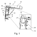
- Fig. 1 shows a top section of a door arrangement 2 according to the invention.
- a top end 4 of an aircraft door 6 holds a cover plate 8 and a door seal 10, which is held by seal retainers 12 and 14.
- the door seal 10 is in contact with a door seal seat 16 of a door frame 18.
- the door frame 18 is mechanically coupled with the fuselage structure 20, follows the contour of the access opening 22 and is adapted for introducing mechanical loads from the door 6 into the fuselage structure 20.
- a hollow space 24 is created, which may act as a resonator and amplify noise emanating from a fluttering cover plate 8.
- a dampening part 26 is introduced as an intermediate body into an edge region of the access opening 22.
- the dampening part 26 is comparable with the door seal 10, as it is a compressible component made of an elastic material and attached to the door frame 18 by means of seal retainers 28 and 30.
- the dampening part 26 comprises a sealing lip 27, which is brought into contact with an interior surface 29 of the cover plate 8.
- the hollow space 24 is clearly reduced in size and the flutter tendency of the cover plate 8 is reduced. Further, as the dampening part 26 may exert a slight force onto an interior side of the cover plate 8 due to its compression, any excited oscillation motions of the cover plate 8 may be dampened.
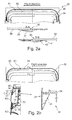
- FIG. 2a and 2b another exemplary embodiment, which may be an addition or an alternative to the exemplary embodiment shown in Fig. 1 .
- a front view of an upper region of a door arrangement 32 is shown, wherein the flight direction of the aircraft, to which the door arrangement 32 belongs, is indicated by an arrow.
- a filler panel 34 is integrated to an edge region of an access opening 36 as an intermediate part, which filler panel 34 is attached to the door frame 18 visible in Fig. 2b.
- Fig. 2a demonstrates two lateral sections in detail with two sectional views A-A and B-B.
- the filler panel 34 comprises a flat portion 37 directly attached to an outer surface of a fuselage skin 38 and extending toward the interior, i.e. the center, of the access opening 36.
- the thickness of the flat portion 37 decreases in an outwards direction. Especially in the lateral sections of the filler panel 34, this may support the aerodynamic efficiency of the whole transition between fuselage skin 38, filler panel 34 and cover plate 40, such that a least possible vorticity is created.
- the filler panel 34 has a frame base 35, which has a plurality of interconnected stiffening parts, which frame base 35 extends into the interior of the access opening 36.
- the frame base 35 is further attached to a flange 39, which in turn is attached to the door frame 18.
- the flat portion 37 is carried by the frame base 35.
- the cover plate 40 slides on the flat portion 37 and will increasingly be deflected into an outwards direction. Due to the deflection, it is tensioned, such that it constantly urges to the outer surface of the fuselage. The tensioning thereby depends on the thickness of the flat portion 37 and the shape of the frame base 35, i.e. the achievable distance from an outside surface of the fuselage and the upper edge of the cover plate 40.
- cover plate 40 In case the cover plate 40 is already pre-tensioned to snugly fit against the fuselage of the aircraft, this tensioning force will be further increased through the filler panel 34 and the fluttering tendency of the cover plate 40 is further reduced. Furthermore, the cover plate 40 may be reduced in size compared to conventional cover plates.
- the filler panel 34 provides a sliding surface for the upper edge 41 of the cover plate 40 for prohibiting that the upper edge 41 touches any seal between in an edge region of the access opening 36.
- Figs. 3a and 3b show a door arrangement 44, which is based on the door arrangement of the previous Figs. 2a and 2b , but with slight modifications.
- section A-A which is associated with a first lateral section of a filler panel 46 facing into the flight direction, a recess 48 is located, into which an outer edge 50 of cover plate 52 comes to rest when an aircraft door 47 is closed.
- the recess 48 as well as a ramp-like outer surface 56 of the filler panel 46 in a flat portion 54 may be designed so as to provide a continuous, aerodynamically positive geometry for reducing the risk of an airflow reaching below the outer edge 50 of a cover plate 52.
- this ramp-like outer surface 56 in combination with recess 48 may be considered a spoiler arrangement.
- a second lateral section of the filler panel 46 does not necessarily have to be shaped like the first lateral section.
- the shape equals the shape of the filler panel 34 shown in Fig. 2a .
- the upper section of filler panel 46 corresponds to the design of the upper section of filler panel 34 shown in Fig. 2b .
- Such a design may be beneficial in regions along the fuselage, where higher suction forces are to be expected. For example, this may be the case at doors downstream of a wing root or above a wing, where the direction of flow is heavily influenced by the flow above the wing.
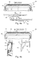
- a door arrangement 58 comprising a filler panel 60 having a more prominent ramp-like surface 62 compared to filler panel 46 of Fig. 3a .
- a lateral section of the filler panel 60 facing into the direction of flight comprises a recess 66, which is adapted for receiving an outer edge 68 of a cover plate 70.
- the filler panel 60 comprises a distinct thickness compared to filler panel 46 of Fig. 3a and may be twice or three times as much as of filler panel 46 or even more. Consequently, it drastically increases the tensioning force onto the cover plate 70, which in turn drastically increases the reduction of fluttering tendency.
- the filler panel 60 may comprise a frame base 69, which carries or comprises a bulge 71.
- the frame base 69 in an interior section 64 covering a part of the access opening comprises a prominent bulge 71, a protrusion or a kink directed away from the access opening, such that the distance between the outer edge of the cover plate 70 to the outer surface of the fuselage is increased.
- such a design is particularly beneficial in a region along the fuselage, where higher suction forces are to be expected, such like at doors downstream of a wing root or above a wing.
- Fig. 5 shows a door arrangement 72 having a cover plate 74, which is laterally cut, i.e. not extending over lateral edges of an access opening 76.
- a filler panel 78 which is attached to a lateral region of the access opening 76.
- a spoiler function may shield a lateral edge of the cover plate 74.
- this is not necessary for a second lateral section of the filler panel 78 facing away from the flight direction.
- the filler panel 78 is rather flat.
- Figs. 6a to 6c show a door arrangement 80, which basically corresponds to the exemplary embodiment shown in Figs. 2a and 2b , while a filler panel 82 is designed as a combination of a flat sheet 84, which is considered a flat portion in view of the above description, a separate base frame 86 attached to the flat sheet 84 as well as a flange 91, to which the base frame 86 is attachable.
- a cover plate 87 rests on the flat sheet sheet 84 of the filler panel 82.
- Fig. 6c shows different approaches for filler panels 89.
- a filler panel 88 is shown, which is made with a casting process. Hence, it comprises a flat portion 90, a base frame 92 and a flange 94 integrally.
- a filler panel 96 is illustrated, which may be made through a cutting process.
- a flat portion 98 and a base frame 100 are combined, while a flange 102 is a separate part.
- a filler panel 104 is shown, which is a group of three single components.
- a flat portion 106 is made from a material sheet, such as a metal or fiber composite sheet, while a base frame 108 may be made through a cutting process, as well as a flange 110, which basically corresponds to the flange 102 in section II or the flange 39 in the above description.
- the actual design or setup of the filler panel may depend on the parts variety and the total number of the filler panels to be manufactured.
Landscapes
- Engineering & Computer Science (AREA)
- Mechanical Engineering (AREA)
- Aviation & Aerospace Engineering (AREA)
- Seal Device For Vehicle (AREA)
Abstract
Description
- The invention relates to an aircraft door arrangement for an aircraft door as well as an aircraft having such an aircraft door arrangement.
- In aircraft design, cover plates for covering a gap in a top region of an aircraft door are used. The cover plate provides an aerodynamically advantageous lining of the gap and furthermore provides a water deflection function. However, in some conditions, an oscillation leading to a fluttering or wobbling motion of at least a part of the cover plate may be induced through the airflow passing the cover plate. Besides producing noise, this may also lead to mechanical stress on the cover plate.
- The noise produced by a fluttering cover plate may be amplified by the hollow space in the gap above the aircraft door, which is delimited by the door frame, an upper delimitation of an access opening for accessing the aircraft fuselage and the aircraft door having a door seal. However, the gap above the aircraft door may not simply be eliminated, as it is required for or supporting the opening and closing motion of the aircraft door.
- Consequently, it may be an object of the invention to provide an aircraft door arrangement, which leads to a clearly reduced fluttering motion of a cover plate and reduced noise emission as well as less mechanical stresses on the cover plate.
- The object is met by an aircraft door arrangement having the features of independent claim 1. Advantageous embodiments and further improvements may be gathered from the sub-claims and the following description.
- An aircraft door arrangement is proposed, the arrangement comprising an access opening in an aircraft fuselage, at least a section of a door frame arranged in the access opening, an aircraft door, a cover plate extending from an outer edge of the aircraft door in an outward direction and adapted for extending onto an outer edge of the access opening when the aircraft door closes the access opening, and at least one intermediate part located in at least one of an inner edge region and an outer edge region of the access opening for inducing a force onto the cover plate directed away from the door frame and adapted for reducing at least one of a flutter tendency of the cover plate and amplification of noise in a hollow space between the cover plate, the door frame and the door, when the door is closed.
- The aircraft door arrangement thereby is defined by an access opening in the fuselage of the aircraft, through which passengers and personnel may enter or leave the aircraft. It goes without saying that an aircraft may comprise a plurality of different access openings, which may be arranged at different locations along the aircraft fuselage. The size of the access openings as well as the shape of the contours of the access openings may vary. Hence, an aircraft may comprise a variety of different aircraft door arrangements according to the invention, which may realize different features according to the invention, without departing from the scope of protection intended.
- The door frame constitutes a mechanical support for the aircraft door and receives and introduces substantially all related forces into the fuselage structure. Preferably, the door frame comprises a shape that corresponds to the shape of the access opening, while the dimensions of the door frame allow to attach the door frame on an interior surface of the fuselage in the access opening region. Hence, when the aircraft door closes the access opening, it is situated in front of the door frame when viewing onto the outer skin of the fuselage.
- Several locking means and movement means may be arranged at the door frame that allow to safely lock the aircraft door in a closed position.
- Further, a door seal may be arranged on an interior side of the aircraft door, which is adapted for providing a flush contact with an associated seat attached to the door frame, when the aircraft door is closed. However, the door seal may also be attached to the door frame and the seat for contacting the door seal may be located at an interior side of the aircraft door. In the locked position of the aircraft door, a hollow space is created delimited by the door frame, the aircraft door, the door seal and the cover plate.
- The cover plate basically is a lining element for lining a gap at a top end of the aircraft door, thereby separating the above-mentioned hollow space from the outside. The cover plate may be made of any suitable material, such as a fiber composite material or other non-metallic or metallic materials, which allows to provide a lightweight lining element.
- The at least one intermediate part is an additional part, which may provide one or two noise reduction functions based on two different working principles, which may support each other for achieving a drastic reduction of noise emanating from the cover plate and/or a fluttering tendency.
- Firstly, the intermediate part may simply provide a force acting on an interior side of the cover plate, i.e. into an outward direction. Together with a pretension or simply alone, this may provide for a very precise and rigid fixation of the cover plate in a predetermined position, which clearly reduces a flutter tendency. The intermediate part may exemplarily at least partially be placed on an outside of the fuselage, i.e. at an outer edge region of the access opening. When the cover plate is brought into position by closing the door, its upper edge will be urged into an outward direction through the intermediate part, which will result in or increase a pretension of the cover plate.
- In a second working principle, the volume of the hollow space mentioned above will be decreased through integration of the intermediate part in the hollow space. This allows to increase the Eigenfrequency (or resonance frequency), which may then be clearly separated from any Eigenfrequency (or resonance frequency) of a fluttering oscillation of the cover plate. Consequently, the tendency of a noise amplification if any fluttering oscillation occurs, will be drastically reduced.
- As indicated above, both working principles may be achieved separately or in combination. A gist of the invention therefore lies in a reduction of mechanical modifications of a conventional door arrangement, which will lead to providing a simple retrofit solution for existing aircraft door arrangements and, furthermore, maintaining the advantageous mechanical characteristics of aircraft door actuation means and door locking means.
- Further, it may be beneficial to design the door arrangement according to the invention such that the cover plate comprises a tension, which leads to the outer edges of the cover plate pressing against the outer surface of the fuselage. The local pressing forces preferably at least compensate any suction force acting on the outside of the cover plate, such that the edges maintain their positions on the fuselage substantially under any circumstances.
- In an advantageous embodiment, at least one of the at least one intermediate part is a flexible dampening part, which is at least partially attached to the door frame and extending into the above-mentioned hollow space. The dampening part may be any part that is adapted for providing a slight force to an interior surface of the cover plate in a direction outwards. The dampening part may extend along a substantial space between the door frame and the cover plate and absorb forces arising through a potential, accidental or sudden flutter motion of the cover plate, while it is in a constant contact with the cover plate. Furthermore, through the use of the dampening part, which comprises a certain volume, the size of the above-mentioned hollow space enclosed between the cover plate, the door frame and a door seal is clearly reduced in size. The resonance frequency of the hollow space is clearly increased. Hence, even when a flutter tendency occurs, the noise generation or amplification in this hollow space is clearly reduced as a resonance is avoided.
- In an advantageous embodiment, the dampening part comprises a compressible profile made of an elastic material. Preferably, the dampening part comprises a hollow interior space, which leads to the ability to provide a rather large volume without requiring an excessive weight. Thus, the dampening part has an excellent weight to volume ratio and may fill a rather large part of the hollow space between the cover plate, the door frame and the door seal. Suitable materials may include synthetic and natural rubber, as well as polyurethane and other elastic material having the ability to withstand the large temperature range that arises in commercial aircraft.
- Still further, the dampening part may be attached to the door frame by means of at least one seal retainer. The seal retainer may be made from a sheet metal having at least one curvature or bend which receives at least a section of the dampening part for supporting its shape.
- Still further, the dampening part may comprise a sealing lip in a region facing away from the door frame. The sealing lip consequently rests snugly on the interior side of the cover plate for slightly exerting a force and for sealingly limit the interior space between cover plate, door frame and door seal.
- In a still further advantageous embodiment at least one of the at least one intermediate part is a filler panel, wherein the filler panel is arranged on an outer side of the edge of the access opening and facing to the center of the access opening. The filler panel at least partially rests on an outer surface of the fuselage in an edge region of the access opening, but extends over a certain section of the access opening. Hence, the cover plate does not need to rest on an edge region of the access opening, but may instead rest on the filler panel. Consequently, the cover plate may be decreased in size, which in turn clearly raises the resonance frequency and increases the stiffness of the cover plate. Resultantly, the flutter tendency is drastically reduced. The filler panel allows to be mounted to the access opening as a retrofit solution, which does not require any further constructional changes of the door arrangement, besides installing a smaller cover plate.
- In a further advantageous embodiment, the filler panel comprises a flat portion that rests on an edge region of the access opening, wherein the thickness of the flat portion decreases in a radial outwards direction, such that a ramp-like shape is formed. During a closing motion of the aircraft door, to which the cover plate is attached, an outer edge region of the cover plate slides on the outer surface of the fuselage. Due to the use of the above-mentioned filler panel, the outer edge of the cover plate slides on the ramp-shaped flat portion to a dedicated end position, leading to a slight deflection of the outer edge of the cover plate in an outwards direction, thereby achieving or further increasing a tensioning of the cover plate. This leads to a more firmly clamping of the cover plate to the fuselage and still further reducing the fluttering tendency. At the same time, as mentioned above, the cover plate may be clearly reduced in size as the filler panel already closes a part of the above-mentioned hollow space.
- It is also conceivable that the filler panel comprises at least one of a bulge, protrusion or kink at least in a top section of the filler panel in an outward direction away from the outer surface of the fuselage. Preferably, the at least one of a bulge, protrusion of kink is located in a region of the filler panel, which is covering the access opening, such that when the aircraft door is closed, the outer edge of the cover plate rests on the at least one of a bulge, protrusion or kink. This leads to a capability to clearly increasing the tensioning of the cover plate, which eliminates the necessity of a pre-tensioning of the cover plate. For conducting the motion of the aircraft door from an open to a position directly above the access opening, before the aircraft door moves down, a door lever has to be moved manually. With a pre-tensioned cover plate, this may increase the required force to move the lever. However, if said bulge, protrusion or kink will be followed by the outer edge of the cover plate, a pre-tensioning may not be necessary, such that the required door lever force may be reduced.
- In a further advantageous embodiment, the filler panel comprises a top portion and two lateral portions, wherein a lateral portion facing into the motion direction of the aircraft comprises a recess, into which the outer edge of the cover plate comes to rest when the aircraft door is closed. This recess may be arranged in the flat portion having the above-mentioned variable thickness, such that the outer edge of the cover plate is sealed from the airflow passing the aircraft. Consequently, the flutter tendency is even more reduced.
- Still further, the cover plate and the filler panel are designed such that when the door is closed the pressing force of the cover plate acting on the filler panel are at least equal to the expected suction forces onto the cover plate during the flight. However it is preferred that the pressing force exceeds the expected suction forces.
- It goes without saying that the filler panel may comprise many different shapes that are primarily determined by the location on the aircraft. For example, the filler panel may comprise a portion that clearly extends into an outwards direction of the aircraft, i.e. facing away from the outer surface of the fuselage, such that an improved sealing may be created for the outer edge of the cover plate.
- The invention also relates to an aircraft having a fuselage comprising at least one access opening including at least one door arrangement.
- Further characteristics, advantages and application options of the present invention are disclosed in the following description of the exemplary embodiments in the figures. All the described and/or illustrated characteristics per se and in any combination form the subject of the invention, even irrespective of their composition in the individual claims or their interrelationships. Furthermore, identical or similar components in the figures have the same reference characters.
-
Fig. 1 shows an exemplary embodiment in a sectional view. -
Fig. 2a and Fig. 2b show a further exemplary embodiment in front views and sectional views. -
Fig. 3a and Fig. 3b show another exemplary embodiment in front views and sectional views. -
Fig. 4a and Fig. 4b show a still further exemplary embodiment in front views and sectional views. -
Fig. 5 shows a further exemplary embodiment with a shortened filler panel. -
Fig. 6a to Fig. 6c show an exemplary embodiment in front views and sectional views. -
Fig. 1 shows a top section of adoor arrangement 2 according to the invention. Here, atop end 4 of an aircraft door 6 holds acover plate 8 and adoor seal 10, which is held byseal retainers fuselage structure 20, thedoor seal 10 is in contact with adoor seal seat 16 of adoor frame 18. In turn, thedoor frame 18 is mechanically coupled with thefuselage structure 20, follows the contour of the access opening 22 and is adapted for introducing mechanical loads from the door 6 into thefuselage structure 20. - Between the
cover plate 8, thedoor seal 10 and an outwards facing side of thedoor frame 18, ahollow space 24 is created, which may act as a resonator and amplify noise emanating from a flutteringcover plate 8. For reducing the size of thishollow space 24, it is proposed to introduce a dampeningpart 26 as an intermediate body into an edge region of theaccess opening 22. In this exemplary embodiment, the dampeningpart 26 is comparable with thedoor seal 10, as it is a compressible component made of an elastic material and attached to thedoor frame 18 by means ofseal retainers part 26 comprises a sealinglip 27, which is brought into contact with aninterior surface 29 of thecover plate 8. - Hence, the
hollow space 24 is clearly reduced in size and the flutter tendency of thecover plate 8 is reduced. Further, as the dampeningpart 26 may exert a slight force onto an interior side of thecover plate 8 due to its compression, any excited oscillation motions of thecover plate 8 may be dampened. - In
Fig. 2a and 2b , another exemplary embodiment, which may be an addition or an alternative to the exemplary embodiment shown inFig. 1 . Here, a front view of an upper region of adoor arrangement 32 is shown, wherein the flight direction of the aircraft, to which thedoor arrangement 32 belongs, is indicated by an arrow. - In addition or as an alternative to the dampening
part 26, afiller panel 34 is integrated to an edge region of an access opening 36 as an intermediate part, whichfiller panel 34 is attached to thedoor frame 18 visible inFig. 2b. Fig. 2a demonstrates two lateral sections in detail with two sectional views A-A and B-B. A first lateral section, associated with sectional view A-A, faces into the flight direction, while a second lateral section, associated with sectional view B-B, faces away from the flight direction. - In this example, the
filler panel 34 comprises aflat portion 37 directly attached to an outer surface of afuselage skin 38 and extending toward the interior, i.e. the center, of theaccess opening 36. The thickness of theflat portion 37 decreases in an outwards direction. Especially in the lateral sections of thefiller panel 34, this may support the aerodynamic efficiency of the whole transition betweenfuselage skin 38,filler panel 34 andcover plate 40, such that a least possible vorticity is created. - However, as shown in
Fig. 2b , this also applies to a top region of thedoor arrangement 32 as indicated in a sectional view C-C. Here it is clearly visible that thefiller panel 34 has aframe base 35, which has a plurality of interconnected stiffening parts, whichframe base 35 extends into the interior of theaccess opening 36. Theframe base 35 is further attached to aflange 39, which in turn is attached to thedoor frame 18. By extending into the interior of the access opening 36, a muchshorter cover plate 40 than in conventional door arrangements may be used. - The
flat portion 37 is carried by theframe base 35. When theaircraft door 42 is in the process of being closed, it will move a certain distance downwards before being locked in thedoor frame 18. During this downward directed motion, thecover plate 40 slides on theflat portion 37 and will increasingly be deflected into an outwards direction. Due to the deflection, it is tensioned, such that it constantly urges to the outer surface of the fuselage. The tensioning thereby depends on the thickness of theflat portion 37 and the shape of theframe base 35, i.e. the achievable distance from an outside surface of the fuselage and the upper edge of thecover plate 40. - In case the
cover plate 40 is already pre-tensioned to snugly fit against the fuselage of the aircraft, this tensioning force will be further increased through thefiller panel 34 and the fluttering tendency of thecover plate 40 is further reduced. Furthermore, thecover plate 40 may be reduced in size compared to conventional cover plates. Thefiller panel 34 provides a sliding surface for theupper edge 41 of thecover plate 40 for prohibiting that theupper edge 41 touches any seal between in an edge region of theaccess opening 36. -
Figs. 3a and 3b show adoor arrangement 44, which is based on the door arrangement of the previousFigs. 2a and 2b , but with slight modifications. Here, in section A-A, which is associated with a first lateral section of afiller panel 46 facing into the flight direction, arecess 48 is located, into which anouter edge 50 ofcover plate 52 comes to rest when anaircraft door 47 is closed. - The
recess 48 as well as a ramp-likeouter surface 56 of thefiller panel 46 in aflat portion 54 may be designed so as to provide a continuous, aerodynamically positive geometry for reducing the risk of an airflow reaching below theouter edge 50 of acover plate 52. Hence, this ramp-likeouter surface 56 in combination withrecess 48 may be considered a spoiler arrangement. - As shown in
Fig. 3b , a second lateral section of thefiller panel 46 does not necessarily have to be shaped like the first lateral section. Here, the shape equals the shape of thefiller panel 34 shown inFig. 2a . Still further, the upper section offiller panel 46 corresponds to the design of the upper section offiller panel 34 shown inFig. 2b . - Such a design may be beneficial in regions along the fuselage, where higher suction forces are to be expected. For example, this may be the case at doors downstream of a wing root or above a wing, where the direction of flow is heavily influenced by the flow above the wing.
- A still further advantageous embodiment is shown in
Figs. 4a and 4b . Here, adoor arrangement 58 is depicted, comprising afiller panel 60 having a more prominent ramp-like surface 62 compared tofiller panel 46 ofFig. 3a . A lateral section of thefiller panel 60 facing into the direction of flight comprises arecess 66, which is adapted for receiving anouter edge 68 of acover plate 70. Thefiller panel 60 comprises a distinct thickness compared tofiller panel 46 ofFig. 3a and may be twice or three times as much as offiller panel 46 or even more. Consequently, it drastically increases the tensioning force onto thecover plate 70, which in turn drastically increases the reduction of fluttering tendency. - As shown in
Fig. 4b , this does not only relate to a lateral section, but also to a top section of thefiller panel 60. Thefiller panel 60 may comprise aframe base 69, which carries or comprises abulge 71. This may be realized in that theframe base 69 in aninterior section 64 covering a part of the access opening comprises aprominent bulge 71, a protrusion or a kink directed away from the access opening, such that the distance between the outer edge of thecover plate 70 to the outer surface of the fuselage is increased. - As mentioned earlier, such a design is particularly beneficial in a region along the fuselage, where higher suction forces are to be expected, such like at doors downstream of a wing root or above a wing.
-
Fig. 5 shows adoor arrangement 72 having acover plate 74, which is laterally cut, i.e. not extending over lateral edges of anaccess opening 76. However, afiller panel 78, which is attached to a lateral region of theaccess opening 76. As indicated in a section A-A., which corresponds to a first lateral section of thefiller panel 78 facing into the flight direction, a spoiler function may shield a lateral edge of thecover plate 74. As indicated in section B-B, this is not necessary for a second lateral section of thefiller panel 78 facing away from the flight direction. Here, thefiller panel 78 is rather flat. - Finally,
Figs. 6a to 6c show adoor arrangement 80, which basically corresponds to the exemplary embodiment shown inFigs. 2a and 2b , while afiller panel 82 is designed as a combination of aflat sheet 84, which is considered a flat portion in view of the above description, aseparate base frame 86 attached to theflat sheet 84 as well as aflange 91, to which thebase frame 86 is attachable. Acover plate 87 rests on theflat sheet sheet 84 of thefiller panel 82. - For the sake of completeness,
Fig. 6c shows different approaches forfiller panels 89. In section I, afiller panel 88 is shown, which is made with a casting process. Hence, it comprises aflat portion 90, abase frame 92 and aflange 94 integrally. In section II, a filler panel 96 is illustrated, which may be made through a cutting process. Here, aflat portion 98 and abase frame 100 are combined, while aflange 102 is a separate part. Still further, in section III a filler panel 104 is shown, which is a group of three single components. Aflat portion 106 is made from a material sheet, such as a metal or fiber composite sheet, while abase frame 108 may be made through a cutting process, as well as aflange 110, which basically corresponds to theflange 102 in section II or theflange 39 in the above description. - The actual design or setup of the filler panel may depend on the parts variety and the total number of the filler panels to be manufactured.
- In addition, it should be pointed out that "comprising" does not exclude other elements or steps, and "a" or "an" does not exclude a plural number. Furthermore, it should be pointed out that characteristics or steps which have been described with reference to one of the above exemplary embodiments can also be used in combination with other characteristics or steps of other exemplary embodiments described above. Reference characters in the claims are not to be interpreted as limitations.
Claims (12)
- Aircraft door arrangement (2, 32, 44, 58, 72, 80), comprising- an access opening (22, 36, 45, 59, 76, 81) in an aircraft fuselage,- at least a section of a door frame (18, 33, 49, 63, 85) arranged in the access opening (22, 36, 45, 59, 76, 81),- an aircraft door (6, 42, 47, 61, 77, 83),- a cover plate (8, 40, 52, 70, 74, 87) extending from an outer edge of the aircraft door (6, 42, 47, 61, 77, 83) in an outward direction and adapted for extending onto an outer edge of the access opening (22, 36, 45, 59, 76, 81) when the aircraft door (6, 42, 47, 61, 77, 83) closes the access opening (22, 36, 45, 59, 76, 81), and- at least one intermediate part (26, 34, 46, 62, 78, 82) located in at least one of an inner edge region and an outer edge region of the access opening (22, 36, 45, 59, 76, 81) for inducing a force onto the cover plate (8, 40, 52, 70, 74, 87) directed away from the door frame (18, 33, 49, 63, 85) and adapted for reducing at least one of a flutter tendency of the cover plate (8, 40, 52, 70, 74, 87) and amplification of noise in a hollow space (24) between the cover plate, the door frame (18, 33, 49, 63, 85) and the aircraft door (6, 42, 47, 61, 77, 83), when the aircraft door (6, 42, 47, 61, 77, 83) is closed.
- Aircraft door arrangement (2, 32, 44, 58, 72, 80) of claim 1,
wherein at least one of the at least one intermediate part (26, 34, 46, 62, 78, 82) is a flexible dampening part (26), which is at least partially attached to the door frame (18, 33, 49, 63, 85) and extending into said hollow space (24). - Aircraft door arrangement (2, 32, 44, 58, 72, 80) of claim 2, wherein the dampening part (26) comprises a compressible profile made of an elastic material.
- Aircraft door arrangement (2, 32, 44, 58, 72, 80) of claim 2 or 3,
wherein the dampening part (26) is attached to the door frame (18, 33, 49, 63, 85) by means of at least one seal retainer (28, 30). - Aircraft door arrangement (2, 32, 44, 58, 72, 80) of one of claims 2 to 4,
wherein the dampening part (26) comprises a sealing lip (27) in a region facing away from the door frame (18, 33, 49, 63, 85). - The door arrangement (2, 32, 44, 58, 72, 80) of any of the previous claims,
wherein at least one of the at least one intermediate part (26, 34, 46, 62, 78, 82) is a filler panel (34, 46, 62, 78, 82),
wherein the filler panel (34, 46, 62, 78, 82) is arranged on an outer side of the edge of the access opening (22, 36, 45, 59, 76, 81) and facing to the center of the access opening (22, 36, 45, 59, 76, 81). - The door arrangement (2, 32, 44, 58, 72, 80) of claim 6,
wherein the filler panel (34, 46, 62, 78, 82) comprises a flat portion (37, 54, 84, 90, 98, 106) that rests on an edge region of the access opening (22, 36, 45, 59, 76, 81),
wherein the thickness of the flat portion (37, 54, 84, 90, 98, 106) at least in a top portion of the filler panel (34, 46, 62, 78, 82) decreases in a radial outwards direction, such that a ramp-like shape is formed. - The door arrangement (2, 32, 44, 58, 72, 80) of claim 6 or 7,
wherein the filler panel (34, 46, 62, 78, 82) comprises at least one of a bulge, protrusion or kink (71) at least on a top section of the filler panel (34, 46, 62, 78, 82) in an outward direction away from the outer surface of the fuselage. - The door arrangement (2, 32, 44, 58, 72, 80) of claim 8,
wherein the at least one of a bulge, protrusion of kink (71) is located in a region of the filler panel (34, 46, 62, 78, 82), which is covering the access opening (22, 36, 45, 59, 76, 81), such that when the aircraft door (6, 42, 47, 61, 77, 83) is closed, the outer edge of the cover plate (8, 40, 52, 70, 74, 87) rests on the at least one of a bulge, protrusion or kink (71). - The door arrangement (2, 32, 44, 58, 72, 80) of any of the claims 6 to 9,
wherein the filler panel (34, 46, 62, 78, 82) comprises a top portion and two lateral portions,
wherein a lateral portion facing into the motion direction of the aircraft comprises a recess (48, 66), adapted for receiving an outer edge of the cover plate (8, 40, 52, 70, 74, 87) when the aircraft door (6, 42, 47, 61, 77, 83) is closed. - The door arrangement (2, 32, 44, 58, 72, 80) of any of the claims 6 to 10,
wherein the cover plate (8, 40, 52, 70, 74, 87) and the filler panel (34, 46, 62, 78, 82) are designed such that when the aircraft door (6, 42, 47, 61, 77, 83) is closed the pressing force of the cover plate (8, 40, 52, 70, 74, 87) acting on the filler panel (34, 46, 62, 78, 82) are at least equal to the expected suction forces onto the cover plate (8, 40, 52, 70, 74, 87) during flight. - Aircraft having a fuselage comprising at least one access opening (22, 36, 45, 59, 76, 81) including at least one door arrangement (2, 32, 44, 58, 72, 80) according to one of the claims 1 to 11.
Priority Applications (1)
| Application Number | Priority Date | Filing Date | Title |
|---|---|---|---|
| EP14182910.1A EP2990329B1 (en) | 2014-08-29 | 2014-08-29 | Aircraft having an aircraft door arrangement |
Applications Claiming Priority (1)
| Application Number | Priority Date | Filing Date | Title |
|---|---|---|---|
| EP14182910.1A EP2990329B1 (en) | 2014-08-29 | 2014-08-29 | Aircraft having an aircraft door arrangement |
Publications (2)
| Publication Number | Publication Date |
|---|---|
| EP2990329A1 true EP2990329A1 (en) | 2016-03-02 |
| EP2990329B1 EP2990329B1 (en) | 2018-03-07 |
Family
ID=51429111
Family Applications (1)
| Application Number | Title | Priority Date | Filing Date |
|---|---|---|---|
| EP14182910.1A Not-in-force EP2990329B1 (en) | 2014-08-29 | 2014-08-29 | Aircraft having an aircraft door arrangement |
Country Status (1)
| Country | Link |
|---|---|
| EP (1) | EP2990329B1 (en) |
Cited By (2)
| Publication number | Priority date | Publication date | Assignee | Title |
|---|---|---|---|---|
| US11623727B2 (en) * | 2019-01-24 | 2023-04-11 | Airbus Operations Gmbh | Aircraft-fuselage structure with contoured adapter arrangement for a door |
| US20250289558A1 (en) * | 2024-03-18 | 2025-09-18 | Textron Innovations Inc. | Turbulent airflow deflector for rotorcraft sliding door |
Citations (4)
| Publication number | Priority date | Publication date | Assignee | Title |
|---|---|---|---|---|
| US3647169A (en) * | 1969-02-07 | 1972-03-07 | British Aircraft Corp Ltd | Aircraft doors |
| US6736353B1 (en) * | 1999-05-08 | 2004-05-18 | Eurocopter Deutschland Gmbh | Grooved profile for diverting liquid |
| US20080093504A1 (en) * | 2005-01-07 | 2008-04-24 | Latecoere | Doors of Aircraft Cabins |
| EP2586699A2 (en) * | 2011-10-27 | 2013-05-01 | Airbus Operations GmbH | Cover plate, door covering and aircraft or spacecraft |
-
2014
- 2014-08-29 EP EP14182910.1A patent/EP2990329B1/en not_active Not-in-force
Patent Citations (4)
| Publication number | Priority date | Publication date | Assignee | Title |
|---|---|---|---|---|
| US3647169A (en) * | 1969-02-07 | 1972-03-07 | British Aircraft Corp Ltd | Aircraft doors |
| US6736353B1 (en) * | 1999-05-08 | 2004-05-18 | Eurocopter Deutschland Gmbh | Grooved profile for diverting liquid |
| US20080093504A1 (en) * | 2005-01-07 | 2008-04-24 | Latecoere | Doors of Aircraft Cabins |
| EP2586699A2 (en) * | 2011-10-27 | 2013-05-01 | Airbus Operations GmbH | Cover plate, door covering and aircraft or spacecraft |
Cited By (3)
| Publication number | Priority date | Publication date | Assignee | Title |
|---|---|---|---|---|
| US11623727B2 (en) * | 2019-01-24 | 2023-04-11 | Airbus Operations Gmbh | Aircraft-fuselage structure with contoured adapter arrangement for a door |
| US20250289558A1 (en) * | 2024-03-18 | 2025-09-18 | Textron Innovations Inc. | Turbulent airflow deflector for rotorcraft sliding door |
| US12441452B2 (en) * | 2024-03-18 | 2025-10-14 | Textron Innovations Inc. | Turbulent airflow deflector for rotorcraft sliding door |
Also Published As
| Publication number | Publication date |
|---|---|
| EP2990329B1 (en) | 2018-03-07 |
Similar Documents
| Publication | Publication Date | Title |
|---|---|---|
| RU2482996C2 (en) | Optimised aircraft hatch | |
| US7506838B2 (en) | Air intake structure for aircraft engine | |
| US6581877B2 (en) | Aircraft with ventral fairing and seal for such an aircraft | |
| US8939713B2 (en) | Aerodynamic element for an aircraft nacelle | |
| US6863245B2 (en) | Aerodynamic profile with an adjustable flap | |
| EP2990329B1 (en) | Aircraft having an aircraft door arrangement | |
| US20150344122A1 (en) | Aircraft door and aircraft comprising such an aircraft door | |
| EP2851282A1 (en) | Cover plate and door arrangement for a means of transportation | |
| US20110114796A1 (en) | Device for shrouding an aircraft nacelle | |
| KR20090109098A (en) | How to Assemble the Window of an Aircraft | |
| US20020008179A1 (en) | Aircraft door | |
| WO2017029180A1 (en) | Aircraft door arrangement with a noise reduced hollow space which can be covered by an aircraft door | |
| WO2014168670A1 (en) | Wing flaps for aircraft and methods for making the same | |
| JP2002544040A (en) | Channel channel for guiding liquid | |
| CN105711803B (en) | Front end of an aircraft fitted with a connecting frame between the undercarriage box and the outer skin of the fuselage | |
| EP3676173B1 (en) | Noise abatement systems for retractable leading edge wing slats of an aircraft wing assembly | |
| EP2338787B1 (en) | Sealing of airflow between a wing and a fuselage | |
| US7422177B2 (en) | Sealing device for a flap track in a belly fairing of an aircraft for a flap-actuating shaft | |
| CN106660627A (en) | Buffer zone for interior aircraft features | |
| US8226037B2 (en) | Aircraft door assembly, and aircraft fuselage comprising such an aircraft door assembly | |
| EP4061703B1 (en) | Slat arrangement for a wing of an aircraft | |
| EP2354605A1 (en) | Sealing profile | |
| US20200070951A1 (en) | Noise reduced end rib assembly for a high-lift device of an aircraft | |
| US10611455B2 (en) | Aircraft assembly comprising a self-stiffened panel assembled with a structural element by means of an alternation of terminal ribs and terminal tabs | |
| CN112389673A (en) | Nut plate assembly |
Legal Events
| Date | Code | Title | Description |
|---|---|---|---|
| PUAI | Public reference made under article 153(3) epc to a published international application that has entered the european phase |
Free format text: ORIGINAL CODE: 0009012 |
|
| AK | Designated contracting states |
Kind code of ref document: A1 Designated state(s): AL AT BE BG CH CY CZ DE DK EE ES FI FR GB GR HR HU IE IS IT LI LT LU LV MC MK MT NL NO PL PT RO RS SE SI SK SM TR |
|
| AX | Request for extension of the european patent |
Extension state: BA ME |
|
| 17P | Request for examination filed |
Effective date: 20160902 |
|
| RBV | Designated contracting states (corrected) |
Designated state(s): AL AT BE BG CH CY CZ DE DK EE ES FI FR GB GR HR HU IE IS IT LI LT LU LV MC MK MT NL NO PL PT RO RS SE SI SK SM TR |
|
| STAA | Information on the status of an ep patent application or granted ep patent |
Free format text: STATUS: EXAMINATION IS IN PROGRESS |
|
| 17Q | First examination report despatched |
Effective date: 20170131 |
|
| GRAP | Despatch of communication of intention to grant a patent |
Free format text: ORIGINAL CODE: EPIDOSNIGR1 |
|
| STAA | Information on the status of an ep patent application or granted ep patent |
Free format text: STATUS: GRANT OF PATENT IS INTENDED |
|
| INTG | Intention to grant announced |
Effective date: 20170927 |
|
| GRAS | Grant fee paid |
Free format text: ORIGINAL CODE: EPIDOSNIGR3 |
|
| GRAA | (expected) grant |
Free format text: ORIGINAL CODE: 0009210 |
|
| STAA | Information on the status of an ep patent application or granted ep patent |
Free format text: STATUS: THE PATENT HAS BEEN GRANTED |
|
| AK | Designated contracting states |
Kind code of ref document: B1 Designated state(s): AL AT BE BG CH CY CZ DE DK EE ES FI FR GB GR HR HU IE IS IT LI LT LU LV MC MK MT NL NO PL PT RO RS SE SI SK SM TR |
|
| REG | Reference to a national code |
Ref country code: GB Ref legal event code: FG4D |
|
| REG | Reference to a national code |
Ref country code: CH Ref legal event code: EP Ref country code: AT Ref legal event code: REF Ref document number: 976258 Country of ref document: AT Kind code of ref document: T Effective date: 20180315 |
|
| REG | Reference to a national code |
Ref country code: IE Ref legal event code: FG4D |
|
| REG | Reference to a national code |
Ref country code: DE Ref legal event code: R096 Ref document number: 602014021895 Country of ref document: DE |
|
| REG | Reference to a national code |
Ref country code: NL Ref legal event code: MP Effective date: 20180307 |
|
| REG | Reference to a national code |
Ref country code: LT Ref legal event code: MG4D |
|
| PG25 | Lapsed in a contracting state [announced via postgrant information from national office to epo] |
Ref country code: FI Free format text: LAPSE BECAUSE OF FAILURE TO SUBMIT A TRANSLATION OF THE DESCRIPTION OR TO PAY THE FEE WITHIN THE PRESCRIBED TIME-LIMIT Effective date: 20180307 Ref country code: NO Free format text: LAPSE BECAUSE OF FAILURE TO SUBMIT A TRANSLATION OF THE DESCRIPTION OR TO PAY THE FEE WITHIN THE PRESCRIBED TIME-LIMIT Effective date: 20180607 Ref country code: ES Free format text: LAPSE BECAUSE OF FAILURE TO SUBMIT A TRANSLATION OF THE DESCRIPTION OR TO PAY THE FEE WITHIN THE PRESCRIBED TIME-LIMIT Effective date: 20180307 Ref country code: HR Free format text: LAPSE BECAUSE OF FAILURE TO SUBMIT A TRANSLATION OF THE DESCRIPTION OR TO PAY THE FEE WITHIN THE PRESCRIBED TIME-LIMIT Effective date: 20180307 Ref country code: CY Free format text: LAPSE BECAUSE OF FAILURE TO SUBMIT A TRANSLATION OF THE DESCRIPTION OR TO PAY THE FEE WITHIN THE PRESCRIBED TIME-LIMIT Effective date: 20180307 Ref country code: LT Free format text: LAPSE BECAUSE OF FAILURE TO SUBMIT A TRANSLATION OF THE DESCRIPTION OR TO PAY THE FEE WITHIN THE PRESCRIBED TIME-LIMIT Effective date: 20180307 |
|
| REG | Reference to a national code |
Ref country code: AT Ref legal event code: MK05 Ref document number: 976258 Country of ref document: AT Kind code of ref document: T Effective date: 20180307 |
|
| REG | Reference to a national code |
Ref country code: FR Ref legal event code: PLFP Year of fee payment: 5 |
|
| PG25 | Lapsed in a contracting state [announced via postgrant information from national office to epo] |
Ref country code: BG Free format text: LAPSE BECAUSE OF FAILURE TO SUBMIT A TRANSLATION OF THE DESCRIPTION OR TO PAY THE FEE WITHIN THE PRESCRIBED TIME-LIMIT Effective date: 20180607 Ref country code: GR Free format text: LAPSE BECAUSE OF FAILURE TO SUBMIT A TRANSLATION OF THE DESCRIPTION OR TO PAY THE FEE WITHIN THE PRESCRIBED TIME-LIMIT Effective date: 20180608 Ref country code: RS Free format text: LAPSE BECAUSE OF FAILURE TO SUBMIT A TRANSLATION OF THE DESCRIPTION OR TO PAY THE FEE WITHIN THE PRESCRIBED TIME-LIMIT Effective date: 20180307 Ref country code: LV Free format text: LAPSE BECAUSE OF FAILURE TO SUBMIT A TRANSLATION OF THE DESCRIPTION OR TO PAY THE FEE WITHIN THE PRESCRIBED TIME-LIMIT Effective date: 20180307 Ref country code: SE Free format text: LAPSE BECAUSE OF FAILURE TO SUBMIT A TRANSLATION OF THE DESCRIPTION OR TO PAY THE FEE WITHIN THE PRESCRIBED TIME-LIMIT Effective date: 20180307 |
|
| PG25 | Lapsed in a contracting state [announced via postgrant information from national office to epo] |
Ref country code: EE Free format text: LAPSE BECAUSE OF FAILURE TO SUBMIT A TRANSLATION OF THE DESCRIPTION OR TO PAY THE FEE WITHIN THE PRESCRIBED TIME-LIMIT Effective date: 20180307 Ref country code: NL Free format text: LAPSE BECAUSE OF FAILURE TO SUBMIT A TRANSLATION OF THE DESCRIPTION OR TO PAY THE FEE WITHIN THE PRESCRIBED TIME-LIMIT Effective date: 20180307 Ref country code: IT Free format text: LAPSE BECAUSE OF FAILURE TO SUBMIT A TRANSLATION OF THE DESCRIPTION OR TO PAY THE FEE WITHIN THE PRESCRIBED TIME-LIMIT Effective date: 20180307 Ref country code: RO Free format text: LAPSE BECAUSE OF FAILURE TO SUBMIT A TRANSLATION OF THE DESCRIPTION OR TO PAY THE FEE WITHIN THE PRESCRIBED TIME-LIMIT Effective date: 20180307 Ref country code: AL Free format text: LAPSE BECAUSE OF FAILURE TO SUBMIT A TRANSLATION OF THE DESCRIPTION OR TO PAY THE FEE WITHIN THE PRESCRIBED TIME-LIMIT Effective date: 20180307 Ref country code: PL Free format text: LAPSE BECAUSE OF FAILURE TO SUBMIT A TRANSLATION OF THE DESCRIPTION OR TO PAY THE FEE WITHIN THE PRESCRIBED TIME-LIMIT Effective date: 20180307 |
|
| PG25 | Lapsed in a contracting state [announced via postgrant information from national office to epo] |
Ref country code: CZ Free format text: LAPSE BECAUSE OF FAILURE TO SUBMIT A TRANSLATION OF THE DESCRIPTION OR TO PAY THE FEE WITHIN THE PRESCRIBED TIME-LIMIT Effective date: 20180307 Ref country code: SK Free format text: LAPSE BECAUSE OF FAILURE TO SUBMIT A TRANSLATION OF THE DESCRIPTION OR TO PAY THE FEE WITHIN THE PRESCRIBED TIME-LIMIT Effective date: 20180307 Ref country code: AT Free format text: LAPSE BECAUSE OF FAILURE TO SUBMIT A TRANSLATION OF THE DESCRIPTION OR TO PAY THE FEE WITHIN THE PRESCRIBED TIME-LIMIT Effective date: 20180307 Ref country code: SM Free format text: LAPSE BECAUSE OF FAILURE TO SUBMIT A TRANSLATION OF THE DESCRIPTION OR TO PAY THE FEE WITHIN THE PRESCRIBED TIME-LIMIT Effective date: 20180307 |
|
| REG | Reference to a national code |
Ref country code: DE Ref legal event code: R097 Ref document number: 602014021895 Country of ref document: DE |
|
| PG25 | Lapsed in a contracting state [announced via postgrant information from national office to epo] |
Ref country code: PT Free format text: LAPSE BECAUSE OF FAILURE TO SUBMIT A TRANSLATION OF THE DESCRIPTION OR TO PAY THE FEE WITHIN THE PRESCRIBED TIME-LIMIT Effective date: 20180709 |
|
| PLBE | No opposition filed within time limit |
Free format text: ORIGINAL CODE: 0009261 |
|
| STAA | Information on the status of an ep patent application or granted ep patent |
Free format text: STATUS: NO OPPOSITION FILED WITHIN TIME LIMIT |
|
| PG25 | Lapsed in a contracting state [announced via postgrant information from national office to epo] |
Ref country code: DK Free format text: LAPSE BECAUSE OF FAILURE TO SUBMIT A TRANSLATION OF THE DESCRIPTION OR TO PAY THE FEE WITHIN THE PRESCRIBED TIME-LIMIT Effective date: 20180307 |
|
| 26N | No opposition filed |
Effective date: 20181210 |
|
| PG25 | Lapsed in a contracting state [announced via postgrant information from national office to epo] |
Ref country code: SI Free format text: LAPSE BECAUSE OF FAILURE TO SUBMIT A TRANSLATION OF THE DESCRIPTION OR TO PAY THE FEE WITHIN THE PRESCRIBED TIME-LIMIT Effective date: 20180307 |
|
| PG25 | Lapsed in a contracting state [announced via postgrant information from national office to epo] |
Ref country code: MC Free format text: LAPSE BECAUSE OF FAILURE TO SUBMIT A TRANSLATION OF THE DESCRIPTION OR TO PAY THE FEE WITHIN THE PRESCRIBED TIME-LIMIT Effective date: 20180307 |
|
| REG | Reference to a national code |
Ref country code: CH Ref legal event code: PL |
|
| PG25 | Lapsed in a contracting state [announced via postgrant information from national office to epo] |
Ref country code: CH Free format text: LAPSE BECAUSE OF NON-PAYMENT OF DUE FEES Effective date: 20180831 Ref country code: LU Free format text: LAPSE BECAUSE OF NON-PAYMENT OF DUE FEES Effective date: 20180829 Ref country code: LI Free format text: LAPSE BECAUSE OF NON-PAYMENT OF DUE FEES Effective date: 20180831 |
|
| REG | Reference to a national code |
Ref country code: BE Ref legal event code: MM Effective date: 20180831 |
|
| PG25 | Lapsed in a contracting state [announced via postgrant information from national office to epo] |
Ref country code: BE Free format text: LAPSE BECAUSE OF NON-PAYMENT OF DUE FEES Effective date: 20180831 |
|
| PG25 | Lapsed in a contracting state [announced via postgrant information from national office to epo] |
Ref country code: MT Free format text: LAPSE BECAUSE OF NON-PAYMENT OF DUE FEES Effective date: 20180829 |
|
| PG25 | Lapsed in a contracting state [announced via postgrant information from national office to epo] |
Ref country code: TR Free format text: LAPSE BECAUSE OF FAILURE TO SUBMIT A TRANSLATION OF THE DESCRIPTION OR TO PAY THE FEE WITHIN THE PRESCRIBED TIME-LIMIT Effective date: 20180307 |
|
| PG25 | Lapsed in a contracting state [announced via postgrant information from national office to epo] |
Ref country code: HU Free format text: LAPSE BECAUSE OF FAILURE TO SUBMIT A TRANSLATION OF THE DESCRIPTION OR TO PAY THE FEE WITHIN THE PRESCRIBED TIME-LIMIT; INVALID AB INITIO Effective date: 20140829 Ref country code: IE Free format text: LAPSE BECAUSE OF NON-PAYMENT OF DUE FEES Effective date: 20180829 Ref country code: MK Free format text: LAPSE BECAUSE OF NON-PAYMENT OF DUE FEES Effective date: 20180307 |
|
| PG25 | Lapsed in a contracting state [announced via postgrant information from national office to epo] |
Ref country code: IS Free format text: LAPSE BECAUSE OF FAILURE TO SUBMIT A TRANSLATION OF THE DESCRIPTION OR TO PAY THE FEE WITHIN THE PRESCRIBED TIME-LIMIT Effective date: 20180707 |
|
| PGFP | Annual fee paid to national office [announced via postgrant information from national office to epo] |
Ref country code: FR Payment date: 20210819 Year of fee payment: 8 |
|
| PGFP | Annual fee paid to national office [announced via postgrant information from national office to epo] |
Ref country code: GB Payment date: 20210820 Year of fee payment: 8 Ref country code: DE Payment date: 20210819 Year of fee payment: 8 |
|
| REG | Reference to a national code |
Ref country code: DE Ref legal event code: R119 Ref document number: 602014021895 Country of ref document: DE |
|
| GBPC | Gb: european patent ceased through non-payment of renewal fee |
Effective date: 20220829 |
|
| PG25 | Lapsed in a contracting state [announced via postgrant information from national office to epo] |
Ref country code: FR Free format text: LAPSE BECAUSE OF NON-PAYMENT OF DUE FEES Effective date: 20220831 Ref country code: DE Free format text: LAPSE BECAUSE OF NON-PAYMENT OF DUE FEES Effective date: 20230301 |
|
| PG25 | Lapsed in a contracting state [announced via postgrant information from national office to epo] |
Ref country code: GB Free format text: LAPSE BECAUSE OF NON-PAYMENT OF DUE FEES Effective date: 20220829 |