EP2990222A1 - Aircraft tire - Google Patents
Aircraft tire Download PDFInfo
- Publication number
- EP2990222A1 EP2990222A1 EP14789121.2A EP14789121A EP2990222A1 EP 2990222 A1 EP2990222 A1 EP 2990222A1 EP 14789121 A EP14789121 A EP 14789121A EP 2990222 A1 EP2990222 A1 EP 2990222A1
- Authority
- EP
- European Patent Office
- Prior art keywords
- tire
- circumferential direction
- portions
- belt protection
- belt
- Prior art date
- Legal status (The legal status is an assumption and is not a legal conclusion. Google has not performed a legal analysis and makes no representation as to the accuracy of the status listed.)
- Granted
Links
Images


Classifications
-
- B—PERFORMING OPERATIONS; TRANSPORTING
- B60—VEHICLES IN GENERAL
- B60C—VEHICLE TYRES; TYRE INFLATION; TYRE CHANGING; CONNECTING VALVES TO INFLATABLE ELASTIC BODIES IN GENERAL; DEVICES OR ARRANGEMENTS RELATED TO TYRES
- B60C9/00—Reinforcements or ply arrangement of pneumatic tyres
- B60C9/18—Structure or arrangement of belts or breakers, crown-reinforcing or cushioning layers
- B60C9/20—Structure or arrangement of belts or breakers, crown-reinforcing or cushioning layers built-up from rubberised plies each having all cords arranged substantially parallel
-
- B—PERFORMING OPERATIONS; TRANSPORTING
- B60—VEHICLES IN GENERAL
- B60C—VEHICLE TYRES; TYRE INFLATION; TYRE CHANGING; CONNECTING VALVES TO INFLATABLE ELASTIC BODIES IN GENERAL; DEVICES OR ARRANGEMENTS RELATED TO TYRES
- B60C9/00—Reinforcements or ply arrangement of pneumatic tyres
- B60C9/18—Structure or arrangement of belts or breakers, crown-reinforcing or cushioning layers
- B60C9/20—Structure or arrangement of belts or breakers, crown-reinforcing or cushioning layers built-up from rubberised plies each having all cords arranged substantially parallel
- B60C9/22—Structure or arrangement of belts or breakers, crown-reinforcing or cushioning layers built-up from rubberised plies each having all cords arranged substantially parallel the plies being arranged with all cords disposed along the circumference of the tyre
-
- B—PERFORMING OPERATIONS; TRANSPORTING
- B60—VEHICLES IN GENERAL
- B60C—VEHICLE TYRES; TYRE INFLATION; TYRE CHANGING; CONNECTING VALVES TO INFLATABLE ELASTIC BODIES IN GENERAL; DEVICES OR ARRANGEMENTS RELATED TO TYRES
- B60C11/00—Tyre tread bands; Tread patterns; Anti-skid inserts
- B60C11/03—Tread patterns
-
- B—PERFORMING OPERATIONS; TRANSPORTING
- B60—VEHICLES IN GENERAL
- B60C—VEHICLE TYRES; TYRE INFLATION; TYRE CHANGING; CONNECTING VALVES TO INFLATABLE ELASTIC BODIES IN GENERAL; DEVICES OR ARRANGEMENTS RELATED TO TYRES
- B60C9/00—Reinforcements or ply arrangement of pneumatic tyres
- B60C9/0057—Reinforcements comprising preshaped elements, e.g. undulated or zig-zag filaments
-
- B—PERFORMING OPERATIONS; TRANSPORTING
- B60—VEHICLES IN GENERAL
- B60C—VEHICLE TYRES; TYRE INFLATION; TYRE CHANGING; CONNECTING VALVES TO INFLATABLE ELASTIC BODIES IN GENERAL; DEVICES OR ARRANGEMENTS RELATED TO TYRES
- B60C11/00—Tyre tread bands; Tread patterns; Anti-skid inserts
- B60C11/03—Tread patterns
- B60C11/04—Tread patterns in which the raised area of the pattern consists only of continuous circumferential ribs, e.g. zig-zag
-
- B—PERFORMING OPERATIONS; TRANSPORTING
- B60—VEHICLES IN GENERAL
- B60C—VEHICLE TYRES; TYRE INFLATION; TYRE CHANGING; CONNECTING VALVES TO INFLATABLE ELASTIC BODIES IN GENERAL; DEVICES OR ARRANGEMENTS RELATED TO TYRES
- B60C9/00—Reinforcements or ply arrangement of pneumatic tyres
- B60C9/18—Structure or arrangement of belts or breakers, crown-reinforcing or cushioning layers
- B60C2009/1828—Structure or arrangement of belts or breakers, crown-reinforcing or cushioning layers characterised by special physical properties of the belt ply
-
- B—PERFORMING OPERATIONS; TRANSPORTING
- B60—VEHICLES IN GENERAL
- B60C—VEHICLE TYRES; TYRE INFLATION; TYRE CHANGING; CONNECTING VALVES TO INFLATABLE ELASTIC BODIES IN GENERAL; DEVICES OR ARRANGEMENTS RELATED TO TYRES
- B60C9/00—Reinforcements or ply arrangement of pneumatic tyres
- B60C9/18—Structure or arrangement of belts or breakers, crown-reinforcing or cushioning layers
- B60C9/20—Structure or arrangement of belts or breakers, crown-reinforcing or cushioning layers built-up from rubberised plies each having all cords arranged substantially parallel
- B60C2009/2048—Structure or arrangement of belts or breakers, crown-reinforcing or cushioning layers built-up from rubberised plies each having all cords arranged substantially parallel characterised by special physical properties of the belt plies
-
- B—PERFORMING OPERATIONS; TRANSPORTING
- B60—VEHICLES IN GENERAL
- B60C—VEHICLE TYRES; TYRE INFLATION; TYRE CHANGING; CONNECTING VALVES TO INFLATABLE ELASTIC BODIES IN GENERAL; DEVICES OR ARRANGEMENTS RELATED TO TYRES
- B60C9/00—Reinforcements or ply arrangement of pneumatic tyres
- B60C9/18—Structure or arrangement of belts or breakers, crown-reinforcing or cushioning layers
- B60C9/20—Structure or arrangement of belts or breakers, crown-reinforcing or cushioning layers built-up from rubberised plies each having all cords arranged substantially parallel
- B60C9/22—Structure or arrangement of belts or breakers, crown-reinforcing or cushioning layers built-up from rubberised plies each having all cords arranged substantially parallel the plies being arranged with all cords disposed along the circumference of the tyre
- B60C2009/2223—Structure or arrangement of belts or breakers, crown-reinforcing or cushioning layers built-up from rubberised plies each having all cords arranged substantially parallel the plies being arranged with all cords disposed along the circumference of the tyre with an interrupted zero degree ply, e.g. using two or more portions for the same ply
-
- B—PERFORMING OPERATIONS; TRANSPORTING
- B60—VEHICLES IN GENERAL
- B60C—VEHICLE TYRES; TYRE INFLATION; TYRE CHANGING; CONNECTING VALVES TO INFLATABLE ELASTIC BODIES IN GENERAL; DEVICES OR ARRANGEMENTS RELATED TO TYRES
- B60C11/00—Tyre tread bands; Tread patterns; Anti-skid inserts
- B60C11/03—Tread patterns
- B60C2011/0337—Tread patterns characterised by particular design features of the pattern
- B60C2011/0339—Grooves
- B60C2011/0341—Circumferential grooves
-
- B—PERFORMING OPERATIONS; TRANSPORTING
- B60—VEHICLES IN GENERAL
- B60C—VEHICLE TYRES; TYRE INFLATION; TYRE CHANGING; CONNECTING VALVES TO INFLATABLE ELASTIC BODIES IN GENERAL; DEVICES OR ARRANGEMENTS RELATED TO TYRES
- B60C2200/00—Tyres specially adapted for particular applications
- B60C2200/02—Tyres specially adapted for particular applications for aircrafts
Definitions
- the present invention relates to an aircraft tire, primarily for use in passenger aircraft or the like.
- JP-A Japanese Patent Application Laid-Open ( JP-A) No. 2012-153310 describes an aircraft tire including a belt layer at the tire radial direction outside of a carcass, in which a sheet shaped belt protection layer (belt protection member) that protects the belt layer is wound in the tire circumferential direction at the circumferential outside of the belt layer.
- a sheet shaped belt protection layer belt protection member
- the belt protection member contacts the protruding object, enabling ingress of the protruding object into the belt layer to be suppressed.
- a large centrifugal force arises in the aircraft tire due to high speed rotation during take-off and landing. Due to the centrifugal force, there are accordingly concerns of bulging out at portions of weaker strength, such as a joint in the belt protection member, and of the dimensions and mass becoming uneven around the tire circumferential direction.
- an object of the present invention is to provide an aircraft tire that suppresses the dimensions and mass of the aircraft tire from becoming uneven around the tire circumferential direction.
- An aircraft tire according to a first aspect includes: a belt layer provided further to a tire radial direction outer side than a carcass; and a sheet shaped belt protection member that is wound in a tire circumferential direction between a tread section and the belt layer, and that includes incision portions incised in a tire width direction, with the incision portions formed at uniform intervals in the tire circumferential direction.
- the present invention enables the dimensions and mass of the aircraft tire to be suppressed from becoming uneven around the tire circumferential direction.
- the arrow TW indicates a direction parallel to the axis of rotation of the tire 10 (referred to below as the “tire width direction” as appropriate).
- the arrow TR indicates a radial direction passing through the axis of rotation of the tire 10 orthogonally to the tire width direction (referred to below as the “tire radial direction” as appropriate).
- the arrow TC indicates the circumferential direction of a circle centered on the axis of rotation of the tire 10 (referred to below as the "tire circumferential direction” as appropriate).
- CL indicates an equatorial plane (a face perpendicular to the axis of rotation of the tire, and passing through the axial direction center of the tire 10).
- the tire 10 includes a carcass 12 straddling a pair of bead cores, not illustrated in the drawings, a belt layer 14 provided at the tire radial direction outside of the carcass 12, and a belt protection layer 20 provided at the tire radial direction outside of the belt layer 14.
- the carcass 12 is configured by at least one carcass ply, and the carcass ply is formed by covering plural cords 12A (such as organic fiber cords or metal cords) with covering rubber (see Fig. 2 ).
- the belt layer 14 is provided at the tire radial direction outside of the carcass 12, and the belt layer 14 is configured including an inner belt layer 16 and an outer belt layer 18 in sequence from the tire radial direction inside.
- the inner belt layer 16 is formed from plural cords 16A (such as organic fiber cords or metal cords) extending around the tire circumferential direction, and a tire width direction intermediate portion side of the inner belt layer 16 (in the vicinity of the equatorial plane CL) is thicker than both tire width direction edge portions of the inner belt layer 16 (see Fig. 1 ).
- the outer belt layer 18 is formed from plural cords 18A (such as organic fiber cords or metal cords) that are oblique with respect to the tire circumferential direction, and as an example in the present exemplary embodiment, the cords 18A are configured so as to intersect with each other. However, there is no limitation thereto, and cords 18A may be formed so as not to intersect with each other.
- cords 18A such as organic fiber cords or metal cords
- the belt protection layer 20 serving as a sheet shaped belt protection member, is provided at the tire radial direction outside of the outer belt layer 18.
- the belt protection layer 20 is formed by plural wave-shaped cords 20A (such as organic fiber cords or metal cords) extending around the tire circumferential direction and covered with a covering rubber.
- the belt protection layer 20 is formed from wave-shaped cords with an amplitude direction in the tire width direction.
- the belt protection layer 20 may be formed from cords extending in zigzag shapes or crank shapes.
- a single belt protection layer 20 is provided in the present exemplary embodiment; however, plural of the belt protection layers 20 may be stacked together.
- the belt protection layer 20 is formed by winding an elongated sheet onto the circumferential outside of the outer belt layer 18, and includes a joint 20B where end portions of the belt protection layer 20 abut each other.
- a single belt protection layer 20 is employed, and the joint 20B is formed only at a single location.
- plural joints 20B may be provided.
- a tread section 22 that is formed from tread rubber and contacts the pavement is provided at the tire radial direction outside of the belt protection layer 20.
- the tread section 22 is formed with plural circumferential direction grooves extending in the tire circumferential direction, and more specifically, as illustrated in Fig. 2 , the tread section 22 is formed with a pair of left and right first circumferential direction grooves 24 on either side of the equatorial plane CL, and a pair of left and right second circumferential direction grooves 26 provided at the tire width direction outside of each first circumferential direction groove 24.
- the four circumferential direction grooves mentioned above are provided.
- three circumferential direction grooves may be formed on both the left and right sides of the equatorial plane CL, to give a total of six.
- the pair of left and right first circumferential direction grooves 24 alone may be formed.
- a first land portion 28 demarcated by the first circumferential direction grooves 24 is provided at the tire width direction intermediate portion of the tread section 22.
- Second land portions 30 demarcated by the first circumferential direction grooves 24 and the second circumferential direction grooves 26 are each provided at the tire width direction outside of the first land portion 28.
- Shoulder portions 32 are provided on both tire width direction edge portions of the tread section 22 at the tire width direction outside of the respective second land portions 30.
- a width (tire width direction length) W1 of the first land portion 28 is formed wider than a width W2 of each of the second land portions 30.
- the second land portions 30 provided at two locations on either side of the equatorial plane CL are both formed with the same width W2 as each other.
- the shoulder portions 32 provided at two locations are also formed with the same width. Note that there is no limitation thereto, and, for example, the widths of the second land portions 30 formed at two locations may be formed with different widths to each other. Moreover, the width of the second land portions 30 may be formed wider than the width of the first land portion 28.
- the belt protection layer 20 is incised at uniform intervals in the tire circumferential direction.
- the belt protection layer 20 positioned within the first land portion 28 (on the tire radial direction inside of the first land portion 28) is formed with first incision portions 36 by incising the belt protection layer 20 at uniform intervals in the tire circumferential direction.
- the first incision portions 36 are formed at 24 locations at uniform intervals in the tire circumferential direction; however, there is no limitation thereto, and the incision locations of the first incision portions 36 are set as appropriate according to the strength demanded of the belt protection layer 20, and so on.
- the first incision portions 36 extend along the tire width direction, and the incision length of each first incision portion 36 is configured as by incising over the same width as the width of the first land portion 28.
- the first incision portions 36 are narrow incisions, in a state forming hardly any gaps in the belt protection layer 20.
- the belt layer 14 and the like on the tire radial direction inside of the belt protection layer 20 are not incised, and only the belt protection layer 20 is incised to configure the first incision portions 36. Note that it is sufficient that the first incision portions 36 incise the wave-shaped cords 20A configuring the belt protection layer 20, and the covering rubber covering the wave-shaped cords 20A may be continuous, and not incised.
- the belt protection layer 20 positioned within the second land portions 30 is formed with second incision portions 38 by incising the belt protection layer 20 at uniform intervals in the tire circumferential direction.
- the second incision portions 38 extend along the tire width direction, and the incision length of each second incision portion 38 is configured by incising over the same width as the width of the second land portions 30.
- the second incision portions 38 are formed by incising the belt protection layer 20 alone, and the belt layer 14 is not incised.
- the first incision portions 36 and the second incision portions 38 are formed by incising mutually different positions around the circumferential direction.
- the second incision portions 38 are formed at intermediate portions of a pitch P1 of the first incision portions 36; however, there is no limitation thereto, and the second incision portions 38 may be configured by incising at portions away from the intermediate portions of the pitch P1.
- the first incision portions 36 and the second incision portions 38 may be formed at the same positions as each other around the tire circumferential direction.
- the first incision portions 36 are formed at a narrower pitch than the second incision portions 38.
- the pitch P1 of the first incision portions 36 is formed as a pitch that is half a pitch P2 of the second incision portions 38; however, there is no limitation thereto.
- the pitch P2 of the second incision portions 38 may be three times the pitch P1 of the first incision portions 36.
- configuration is made such that the ratio of the width W1 of the first land portion 28 against the width W2 of each second land portion 30 is inversely proportional to the ratio of the pitch P1 of the first incision portions 36 against the pitch P2 of the second incision portions 38.
- the pitch P1 of the first incision portions 36 is preferably formed as half the pitch P2 of the second incision portions 38.
- the belt protection layer 20 positioned within the shoulder portions 32 is not is incised; however, the belt protection layer 20 may be incised at uniform intervals in the tire circumferential direction, similarly to the first land portion 28 and the second land portions 30.
- the first incision portions 36 and the second incision portions 38 are formed by incising the belt protection layer 20 along the tire width direction; however, there is no limitation thereto.
- the incisions may be formed obliquely with respect to the tire width direction.
- the first incision portions 36 and the second incision portions 38 are not limited to straight line shapes, and may be zigzag shaped or wave shaped incisions.
- the centrifugal force that arises acts evenly on the joint 20B of the belt protection layer 20, the first incision portions 36, and the second incision portions 38. Accordingly, the centrifugal force acts more evenly around the tire circumferential direction than in a conventional tire in which the belt protection layer 20 is not incised. Accordingly, the joint 20B of the belt protection layer 20, the first incision portions 36, and the second incision portions 38 deform evenly around the tire circumferential direction due to the centrifugal force arising during rotation of the tire 10, thereby enabling bulging at a single location in the tire circumferential direction to be suppressed.
- the air pressure of the aircraft tire 10 is set at a pressure six times or greater than the air pressure of a vehicle tire, the demands for evenness in the dimensions and mass around the tire circumferential direction are greater than in vehicle tires.
- the configuration described above enables air pressure to act evenly around the tire circumferential direction. This thereby enables a reduction in noise and vibration during take-off and landing.
- the belt protection layer 20 is incised across the same width as that of the first land portion 28, and the belt protection layer 20 is not incised, and is continuous, at between the first land portion 28 and second land portions 30. Namely, since the belt protection layer 20 is not incised, and is continuous at portions other than the first incision portions 36 and the second incision portions 38, the strength of the belt protection layer 20 can be better secured than in cases in which the belt protection layer 20 is incised from edge to edge.
- Incising the belt protection layer 20 positioned on the tire radial direction inside of the wide first land portion 28 at a narrow pitch enables the mass within the incised region to approach uniformity around the tire circumferential direction.
- the pitch P1 of the first incision portions 36 formed within the first land portion 28 is a smaller pitch than the pitch P2 of the second incision portions 38 formed within the narrow second land portions 30. Accordingly, the mass in the regions incised by the first incision portions 36 can be made closer to the mass of the regions incised by the second incision portions 38, enabling unevenness in the mass of the tire 10 around the tire circumferential direction to be suppressed.
- the shear strength of cords is reduced when the cords are stretched, making them more liable to break.
- the belt protection layer 20 of the present exemplary embodiment includes wave-shaped cords, such that even when tensile force acts around the tire circumferential direction, the wave-shaped cords do not become stretched, enabling a reduction in the shear strength to be suppressed.
- Example tires and a Comparative Example tire giving a total of four tires, were prepared and tested. Explanation follows regarding the Example tires and the Comparative Example tire used in testing.
- the tires used in testing each had a size of APR30 x 8.8R15, with internal pressure set to standard internal pressure (1500 kPa).
- the belt protection layer 20 of each of the tires on which testing was performed was formed with first incision portions 36 in the same positions as those of the tire 10 of the first exemplary embodiment, and was not formed with the second incision portions 38.
- Table 1 illustrates measurement results for the Examples 1 to 3, taking the number of repetitions for the comparative example as 100. Test conditions were set based on ARP 5257. For cut durability evaluation, the average cut depth was measured after running over a cutter with a blade width of 500 mm. Table 1 illustrates measurement results, with the comparative example set to 100. The higher the value, the higher the durability. Table 1 Comparative Example 1 Example 1 Example 2 Example 3 Number of first incisions 0 8 12 24 Joint durability 100 105 108 108 Cut durability 100 100 99 98
- the tire 50 of the present exemplary embodiment has the same internal structure as the tire 10 of the first exemplary embodiment illustrated in Fig. 1 and Fig. 2 ; however, the locations where the belt protection layer 20 is incised differ from in the tire 10 of the first exemplary embodiment.
- portions of the belt protection layer 20 positioned at the tire radial direction inside of the first land portion 28 are formed with the first incision portions 36 incised at uniform intervals in the tire circumferential direction of the belt protection layer 20, and portions of the belt protection layer 20 positioned at the tire radial direction inside of the second land portions 30 are formed with second incision portions 52, 54 incised at uniform intervals in the tire circumferential direction of the belt protection layer 20.
- the second incision portions 52 and the second incision portions 54 are formed at different positions to each other around the tire circumferential direction.
- the belt protection layer 20 is incised at different positions around the tire circumferential direction, thereby enabling deformation of the tire 50 due to centrifugal force to be made more even around the tire circumferential direction than in cases in which the belt protection layer 20 is incised at a width equal to a positions around the tire circumferential direction.
- making the second incision portions 52 and the second incision portions 54 at different incision locations to each other around the tire circumferential direction enables the dimensions and mass of the tire 50 to be made more even around the tire circumferential direction.
- Other effects are similar to those of the first exemplary embodiment.
- first and second exemplary embodiments of the present invention are not limited to these exemplary embodiments, and obviously various embodiments may be implemented within a range not departing from the spirit of the present invention.
- first circumferential direction grooves 24 and the second circumferential direction grooves 26 may be formed obliquely with respect to the tire circumferential direction, or the tread section 22 may be formed with width direction grooves extending along the tire width direction.
Landscapes
- Engineering & Computer Science (AREA)
- Mechanical Engineering (AREA)
- Tires In General (AREA)
Abstract
Description
- The present invention relates to an aircraft tire, primarily for use in passenger aircraft or the like.
- Japanese Patent Application Laid-Open (
JP-A) No. 2012-153310 - When the aircraft tire described above runs over a protruding object when running, the belt protection member contacts the protruding object, enabling ingress of the protruding object into the belt layer to be suppressed. A large centrifugal force arises in the aircraft tire due to high speed rotation during take-off and landing. Due to the centrifugal force, there are accordingly concerns of bulging out at portions of weaker strength, such as a joint in the belt protection member, and of the dimensions and mass becoming uneven around the tire circumferential direction.
- In consideration of the above circumstances, an object of the present invention is to provide an aircraft tire that suppresses the dimensions and mass of the aircraft tire from becoming uneven around the tire circumferential direction.
- An aircraft tire according to a first aspect includes: a belt layer provided further to a tire radial direction outer side than a carcass; and a sheet shaped belt protection member that is wound in a tire circumferential direction between a tread section and the belt layer, and that includes incision portions incised in a tire width direction, with the incision portions formed at uniform intervals in the tire circumferential direction.
- Due to the above configuration, the present invention enables the dimensions and mass of the aircraft tire to be suppressed from becoming uneven around the tire circumferential direction.
-
-
Fig. 1 is a cross-section taken along the axis of rotation of a tire, illustrating the half of an aircraft tire according to a first exemplary embodiment on the right side of a tire equatorial plane. -
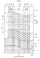
Fig. 2 is a plan view illustrating an internal structure of an aircraft tire according to the first exemplary embodiment. -
Fig. 3 is a plan view illustrating a belt protection member according to the first exemplary embodiment. -
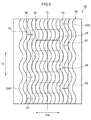
Fig. 4 is a plan view illustrating a belt protection member according to a second exemplary embodiment. - Explanation follows regarding an aircraft tire 10 (referred to below as the tire 10) according to a first exemplary embodiment of the present invention, with reference to the drawings. In the drawings, the arrow TW indicates a direction parallel to the axis of rotation of the tire 10 (referred to below as the "tire width direction" as appropriate). The arrow TR indicates a radial direction passing through the axis of rotation of the
tire 10 orthogonally to the tire width direction (referred to below as the "tire radial direction" as appropriate). The arrow TC indicates the circumferential direction of a circle centered on the axis of rotation of the tire 10 (referred to below as the "tire circumferential direction" as appropriate). In the drawings, CL indicates an equatorial plane (a face perpendicular to the axis of rotation of the tire, and passing through the axial direction center of the tire 10). - As illustrated in
Fig. 1 , thetire 10 according to the present exemplary embodiment includes acarcass 12 straddling a pair of bead cores, not illustrated in the drawings, abelt layer 14 provided at the tire radial direction outside of thecarcass 12, and abelt protection layer 20 provided at the tire radial direction outside of thebelt layer 14. Thecarcass 12 is configured by at least one carcass ply, and the carcass ply is formed by coveringplural cords 12A (such as organic fiber cords or metal cords) with covering rubber (seeFig. 2 ). - The
belt layer 14 is provided at the tire radial direction outside of thecarcass 12, and thebelt layer 14 is configured including aninner belt layer 16 and anouter belt layer 18 in sequence from the tire radial direction inside. As illustrated inFig. 2 , theinner belt layer 16 is formed fromplural cords 16A (such as organic fiber cords or metal cords) extending around the tire circumferential direction, and a tire width direction intermediate portion side of the inner belt layer 16 (in the vicinity of the equatorial plane CL) is thicker than both tire width direction edge portions of the inner belt layer 16 (seeFig. 1 ). - The
outer belt layer 18 is formed fromplural cords 18A (such as organic fiber cords or metal cords) that are oblique with respect to the tire circumferential direction, and as an example in the present exemplary embodiment, thecords 18A are configured so as to intersect with each other. However, there is no limitation thereto, andcords 18A may be formed so as not to intersect with each other. - The
belt protection layer 20, serving as a sheet shaped belt protection member, is provided at the tire radial direction outside of theouter belt layer 18. Thebelt protection layer 20 is formed by plural wave-shaped cords 20A (such as organic fiber cords or metal cords) extending around the tire circumferential direction and covered with a covering rubber. As an example in the present exemplary embodiment, thebelt protection layer 20 is formed from wave-shaped cords with an amplitude direction in the tire width direction. Note that there is no limitation thereto, and for example, thebelt protection layer 20 may be formed from cords extending in zigzag shapes or crank shapes. Moreover, a singlebelt protection layer 20 is provided in the present exemplary embodiment; however, plural of thebelt protection layers 20 may be stacked together. - The
belt protection layer 20 is formed by winding an elongated sheet onto the circumferential outside of theouter belt layer 18, and includes ajoint 20B where end portions of thebelt protection layer 20 abut each other. In the present exemplary embodiment, a singlebelt protection layer 20 is employed, and the joint 20B is formed only at a single location. However, there is no limitation thereto, andplural joints 20B may be provided. - A
tread section 22 that is formed from tread rubber and contacts the pavement is provided at the tire radial direction outside of thebelt protection layer 20. Note that thetread section 22 is formed with plural circumferential direction grooves extending in the tire circumferential direction, and more specifically, as illustrated inFig. 2 , thetread section 22 is formed with a pair of left and right firstcircumferential direction grooves 24 on either side of the equatorial plane CL, and a pair of left and right secondcircumferential direction grooves 26 provided at the tire width direction outside of each firstcircumferential direction groove 24. As an example in the present exemplary embodiment, the four circumferential direction grooves mentioned above are provided. However, there is no limitation thereto, and for example, three circumferential direction grooves may be formed on both the left and right sides of the equatorial plane CL, to give a total of six. Conversely, the pair of left and right first circumferential direction grooves 24 alone may be formed. - A
first land portion 28 demarcated by the firstcircumferential direction grooves 24 is provided at the tire width direction intermediate portion of thetread section 22.Second land portions 30 demarcated by the firstcircumferential direction grooves 24 and the secondcircumferential direction grooves 26 are each provided at the tire width direction outside of thefirst land portion 28.Shoulder portions 32 are provided on both tire width direction edge portions of thetread section 22 at the tire width direction outside of the respectivesecond land portions 30. - A width (tire width direction length) W1 of the
first land portion 28 is formed wider than a width W2 of each of thesecond land portions 30. Thesecond land portions 30 provided at two locations on either side of the equatorial plane CL are both formed with the same width W2 as each other. Theshoulder portions 32 provided at two locations are also formed with the same width. Note that there is no limitation thereto, and, for example, the widths of thesecond land portions 30 formed at two locations may be formed with different widths to each other. Moreover, the width of thesecond land portions 30 may be formed wider than the width of thefirst land portion 28. - Next, detailed explanation follows regarding the
belt protection layer 20. As illustrated inFig. 3 , thebelt protection layer 20 is incised at uniform intervals in the tire circumferential direction. Specifically, thebelt protection layer 20 positioned within the first land portion 28 (on the tire radial direction inside of the first land portion 28) is formed withfirst incision portions 36 by incising thebelt protection layer 20 at uniform intervals in the tire circumferential direction. As an example in the present exemplary embodiment, thefirst incision portions 36 are formed at 24 locations at uniform intervals in the tire circumferential direction; however, there is no limitation thereto, and the incision locations of thefirst incision portions 36 are set as appropriate according to the strength demanded of thebelt protection layer 20, and so on. - The
first incision portions 36 extend along the tire width direction, and the incision length of eachfirst incision portion 36 is configured as by incising over the same width as the width of thefirst land portion 28. Thefirst incision portions 36 are narrow incisions, in a state forming hardly any gaps in thebelt protection layer 20. Thebelt layer 14 and the like on the tire radial direction inside of thebelt protection layer 20 are not incised, and only thebelt protection layer 20 is incised to configure thefirst incision portions 36. Note that it is sufficient that thefirst incision portions 36 incise the wave-shaped cords 20A configuring thebelt protection layer 20, and the covering rubber covering the wave-shaped cords 20A may be continuous, and not incised. - The
belt protection layer 20 positioned within thesecond land portions 30 is formed withsecond incision portions 38 by incising thebelt protection layer 20 at uniform intervals in the tire circumferential direction. Thesecond incision portions 38 extend along the tire width direction, and the incision length of eachsecond incision portion 38 is configured by incising over the same width as the width of thesecond land portions 30. Thesecond incision portions 38 are formed by incising thebelt protection layer 20 alone, and thebelt layer 14 is not incised. - The
first incision portions 36 and thesecond incision portions 38 are formed by incising mutually different positions around the circumferential direction. As an example in the present exemplary embodiment, thesecond incision portions 38 are formed at intermediate portions of a pitch P1 of thefirst incision portions 36; however, there is no limitation thereto, and thesecond incision portions 38 may be configured by incising at portions away from the intermediate portions of the pitch P1. Moreover, thefirst incision portions 36 and thesecond incision portions 38 may be formed at the same positions as each other around the tire circumferential direction. - The
first incision portions 36 are formed at a narrower pitch than thesecond incision portions 38. In the present exemplary embodiment, the pitch P1 of thefirst incision portions 36 is formed as a pitch that is half a pitch P2 of thesecond incision portions 38; however, there is no limitation thereto. For example, the pitch P2 of thesecond incision portions 38 may be three times the pitch P1 of thefirst incision portions 36. Preferably, configuration is made such that the ratio of the width W1 of thefirst land portion 28 against the width W2 of eachsecond land portion 30 is inversely proportional to the ratio of the pitch P1 of thefirst incision portions 36 against the pitch P2 of thesecond incision portions 38. Namely, in cases in which the width W1 of thefirst land portion 28 is twice the width of the width W2 of thesecond land portions 30, the pitch P1 of thefirst incision portions 36 is preferably formed as half the pitch P2 of thesecond incision portions 38. - Note that in the present exemplary embodiment, the
belt protection layer 20 positioned within theshoulder portions 32 is not is incised; however, thebelt protection layer 20 may be incised at uniform intervals in the tire circumferential direction, similarly to thefirst land portion 28 and thesecond land portions 30. Thefirst incision portions 36 and thesecond incision portions 38 are formed by incising thebelt protection layer 20 along the tire width direction; however, there is no limitation thereto. For example, the incisions may be formed obliquely with respect to the tire width direction. Thefirst incision portions 36 and thesecond incision portions 38 are not limited to straight line shapes, and may be zigzag shaped or wave shaped incisions. - Next, explanation follows regarding effects of the
tire 10 according to the present invention. When an aircraft fitted with thetire 10 according to the present invention runs over a protruding object on the pavement, the tread rubber is sometimes penetrated if the protruding object is comparatively large; however, thebelt protection layer 20 contacts the protruding object, enabling ingression of the protruding object into thebelt layer 14 to be suppressed. - When the
tire 10 rotates at high speed during take-off or landing, for example, the centrifugal force that arises acts evenly on the joint 20B of thebelt protection layer 20, thefirst incision portions 36, and thesecond incision portions 38. Accordingly, the centrifugal force acts more evenly around the tire circumferential direction than in a conventional tire in which thebelt protection layer 20 is not incised. Accordingly, the joint 20B of thebelt protection layer 20, thefirst incision portions 36, and thesecond incision portions 38 deform evenly around the tire circumferential direction due to the centrifugal force arising during rotation of thetire 10, thereby enabling bulging at a single location in the tire circumferential direction to be suppressed. Namely, unevenness in the dimensions and mass around the tire circumferential direction of thetire 10 can be suppressed. Moreover, since the air pressure of theaircraft tire 10 is set at a pressure six times or greater than the air pressure of a vehicle tire, the demands for evenness in the dimensions and mass around the tire circumferential direction are greater than in vehicle tires. The configuration described above enables air pressure to act evenly around the tire circumferential direction. This thereby enables a reduction in noise and vibration during take-off and landing. - The
belt protection layer 20 is incised across the same width as that of thefirst land portion 28, and thebelt protection layer 20 is not incised, and is continuous, at between thefirst land portion 28 andsecond land portions 30. Namely, since thebelt protection layer 20 is not incised, and is continuous at portions other than thefirst incision portions 36 and thesecond incision portions 38, the strength of thebelt protection layer 20 can be better secured than in cases in which thebelt protection layer 20 is incised from edge to edge. Bulging under the action of centrifugal force would be more liable to occur if thefirst incision portions 36 and thesecond incision portions 38 were formed at the same positions as each other around the tire circumferential direction, however, deformation of thetire 10 due to centrifugal force can be suppressed due to forming thefirst incision portions 36 and thesecond incision portions 38 at different positions to each other around the tire circumferential direction. - Incising the
belt protection layer 20 positioned on the tire radial direction inside of the widefirst land portion 28 at a narrow pitch enables the mass within the incised region to approach uniformity around the tire circumferential direction. Namely, the pitch P1 of thefirst incision portions 36 formed within thefirst land portion 28 is a smaller pitch than the pitch P2 of thesecond incision portions 38 formed within the narrowsecond land portions 30. Accordingly, the mass in the regions incised by thefirst incision portions 36 can be made closer to the mass of the regions incised by thesecond incision portions 38, enabling unevenness in the mass of thetire 10 around the tire circumferential direction to be suppressed. Moreover, the shear strength of cords is reduced when the cords are stretched, making them more liable to break. However, thebelt protection layer 20 of the present exemplary embodiment includes wave-shaped cords, such that even when tensile force acts around the tire circumferential direction, the wave-shaped cords do not become stretched, enabling a reduction in the shear strength to be suppressed. - In order to confirm the advantageous effects of the
tire 10 according to the present exemplary embodiment, three Example tires and a Comparative Example tire, giving a total of four tires, were prepared and tested. Explanation follows regarding the Example tires and the Comparative Example tire used in testing. The tires used in testing each had a size of APR30 x 8.8R15, with internal pressure set to standard internal pressure (1500 kPa). Thebelt protection layer 20 of each of the tires on which testing was performed was formed withfirst incision portions 36 in the same positions as those of thetire 10 of the first exemplary embodiment, and was not formed with thesecond incision portions 38. - Example 1: A tire formed with the
first incision portions 36 at 8 locations at uniform intervals in the tire circumferential direction - Example 2: A tire formed with the
first incision portions 36 at 12 locations at uniform intervals in the tire circumferential direction - Example 3: A tire formed with the
first incision portions 36 at 24 locations at uniform intervals in the tire circumferential direction - Comparative Example: A conventional tire not formed with the
first incision portions 36. - Test Details: Repeated landing testing was performed, and the number of repetitions until damage to the joint 20B occurred was measured. Table 1 illustrates measurement results for the Examples 1 to 3, taking the number of repetitions for the comparative example as 100. Test conditions were set based on ARP 5257. For cut durability evaluation, the average cut depth was measured after running over a cutter with a blade width of 500 mm. Table 1 illustrates measurement results, with the comparative example set to 100. The higher the value, the higher the durability.
Table 1 Comparative Example 1 Example 1 Example 2 Example 3 Number of first incisions 0 8 12 24 Joint durability 100 105 108 108 Cut durability 100 100 99 98 - As illustrated by the test results in Table 1, it was confirmed that the mass evenness characteristics of the tire are improved, and the joint 20B is made less vulnerable to damage, by increasing the number of the
first incision portions 36. Moreover, regarding cut durability, it was confirmed that no obvious effect on durability is observed even when the number of thefirst incision portions 36 is increased. - Next, explanation follows regarding a
tire 50 according to a second exemplary embodiment of the present invention. Note that configurations similar to in the first exemplary embodiment are allocated the same reference numerals, and explanation thereof is omitted. Thetire 50 of the present exemplary embodiment has the same internal structure as thetire 10 of the first exemplary embodiment illustrated inFig. 1 andFig. 2 ; however, the locations where thebelt protection layer 20 is incised differ from in thetire 10 of the first exemplary embodiment. - As illustrated in
Fig. 4 , portions of thebelt protection layer 20 positioned at the tire radial direction inside of thefirst land portion 28 are formed with thefirst incision portions 36 incised at uniform intervals in the tire circumferential direction of thebelt protection layer 20, and portions of thebelt protection layer 20 positioned at the tire radial direction inside of thesecond land portions 30 are formed withsecond incision portions belt protection layer 20. Thesecond incision portions 52 and thesecond incision portions 54 are formed at different positions to each other around the tire circumferential direction. - In the
tire 50 of the present exemplary embodiment, thebelt protection layer 20 is incised at different positions around the tire circumferential direction, thereby enabling deformation of thetire 50 due to centrifugal force to be made more even around the tire circumferential direction than in cases in which thebelt protection layer 20 is incised at a width equal to a positions around the tire circumferential direction. Namely, making thesecond incision portions 52 and thesecond incision portions 54 at different incision locations to each other around the tire circumferential direction enables the dimensions and mass of thetire 50 to be made more even around the tire circumferential direction. Other effects are similar to those of the first exemplary embodiment. - Explanation has been given regarding the first and second exemplary embodiments of the present invention; however, the present invention is not limited to these exemplary embodiments, and obviously various embodiments may be implemented within a range not departing from the spirit of the present invention. For example, the first
circumferential direction grooves 24 and the secondcircumferential direction grooves 26 may be formed obliquely with respect to the tire circumferential direction, or thetread section 22 may be formed with width direction grooves extending along the tire width direction. - The entire contents of
Japanese Patent Application No. 2013-092585, filed on April 25, 2013 - All cited documents, patent applications and technical standards mentioned in the present specification are incorporated by reference in the present specification to the same extent as if the individual cited document, patent application, or technical standard was specifically and individually indicated to be incorporated by reference.
Claims (5)
- An aircraft tire, comprising:a belt layer provided further to a tire radial direction outer side than a carcass; anda sheet shaped belt protection member that is wound in a tire circumferential direction between a tread section and the belt layer, and that includes incision portions incised in a tire width direction, with the incision portions formed at uniform intervals in the tire circumferential direction.
- The aircraft tire of claim 1, wherein:the tread portion includes a land portion demarcated by a plurality of circumferential direction grooves extending in the tire circumferential direction; andthe belt protection member is incised at a width equal to a width of the land portion.
- The aircraft tire of claim 2, wherein:the tread portion includes a plurality of the land portions; andthe belt protection member is incised at different positions in the tire circumferential direction at positions inside adjacent land portions.
- The aircraft tire of claim 3, wherein the belt protection member is incised at a narrower pitch in the tire circumferential direction at positions within a wide land portion, than at positions where the belt protection member faces a narrow land portion.
- The aircraft tire of any one of claim 1 to claim 4, wherein the belt protection member includes a plurality of wave-shaped cords extending in a wave shape with an amplitude direction in the tire width direction.
Applications Claiming Priority (2)
| Application Number | Priority Date | Filing Date | Title |
|---|---|---|---|
| JP2013092585A JP6014542B2 (en) | 2013-04-25 | 2013-04-25 | Aircraft tire |
| PCT/JP2014/060754 WO2014175126A1 (en) | 2013-04-25 | 2014-04-15 | Aircraft tire |
Publications (3)
| Publication Number | Publication Date |
|---|---|
| EP2990222A1 true EP2990222A1 (en) | 2016-03-02 |
| EP2990222A4 EP2990222A4 (en) | 2016-03-16 |
| EP2990222B1 EP2990222B1 (en) | 2017-03-15 |
Family
ID=51791705
Family Applications (1)
| Application Number | Title | Priority Date | Filing Date |
|---|---|---|---|
| EP14789121.2A Not-in-force EP2990222B1 (en) | 2013-04-25 | 2014-04-15 | Aircraft tire |
Country Status (4)
| Country | Link |
|---|---|
| US (1) | US9902206B2 (en) |
| EP (1) | EP2990222B1 (en) |
| JP (1) | JP6014542B2 (en) |
| WO (1) | WO2014175126A1 (en) |
Cited By (3)
| Publication number | Priority date | Publication date | Assignee | Title |
|---|---|---|---|---|
| EP3006229A4 (en) * | 2013-06-04 | 2016-04-27 | Bridgestone Corp | Pneumatic tire for aircraft |
| CN110667315A (en) * | 2019-10-10 | 2020-01-10 | 江苏通用科技股份有限公司 | Curve high-stretch belt ply structure |
| CN110667314A (en) * | 2019-10-10 | 2020-01-10 | 江苏通用科技股份有限公司 | Novel tire bead profile structure of all-steel load radial tire |
Families Citing this family (1)
| Publication number | Priority date | Publication date | Assignee | Title |
|---|---|---|---|---|
| CN113478880B (en) * | 2021-07-26 | 2023-06-23 | 江苏环柔轮胎科技有限公司 | A variable amplitude corrugated winding method for crown strips |
Family Cites Families (10)
| Publication number | Priority date | Publication date | Assignee | Title |
|---|---|---|---|---|
| IT999224B (en) | 1973-11-06 | 1976-02-20 | Pirelli | IMPROVEMENT OF THE INTERMEDIATE STRUCTURE FOR RADIAL TIRES AND METHOD FOR OBTAINING THIS STRUCTURE |
| US4865098A (en) * | 1983-02-09 | 1989-09-12 | The Goodyear Tire & Rubber Company | Pneumatic aircaft tire |
| JPS61268505A (en) * | 1985-05-21 | 1986-11-28 | Sumitomo Rubber Ind Ltd | Radial tire with high internal pressure |
| JPS62273837A (en) | 1986-05-23 | 1987-11-27 | Yokohama Rubber Co Ltd:The | Pneumatic radial tire for passenger car |
| FR2731654A1 (en) * | 1995-03-16 | 1996-09-20 | Michelin & Cie | ZERO DEGREE REINFORCEMENT FOR TIRES AND CUTTING DEVICE FOR PREPARING SUCH REINFORCEMENT |
| JP4502486B2 (en) * | 2000-09-11 | 2010-07-14 | 株式会社ブリヂストン | Aircraft pneumatic tire |
| US6935393B2 (en) | 2003-10-23 | 2005-08-30 | The Goodyear Tire & Rubber Company | Tire having an overlay for noise improvement |
| JP5067106B2 (en) * | 2007-10-10 | 2012-11-07 | 横浜ゴム株式会社 | Pneumatic tire |
| JP2012071762A (en) * | 2010-09-29 | 2012-04-12 | Bridgestone Corp | Pneumatic radial tire for aircraft |
| JP5739681B2 (en) | 2011-01-28 | 2015-06-24 | 株式会社ブリヂストン | Pneumatic tire |
-
2013
- 2013-04-25 JP JP2013092585A patent/JP6014542B2/en not_active Expired - Fee Related
-
2014
- 2014-04-15 US US14/785,631 patent/US9902206B2/en not_active Expired - Fee Related
- 2014-04-15 WO PCT/JP2014/060754 patent/WO2014175126A1/en not_active Ceased
- 2014-04-15 EP EP14789121.2A patent/EP2990222B1/en not_active Not-in-force
Cited By (4)
| Publication number | Priority date | Publication date | Assignee | Title |
|---|---|---|---|---|
| EP3006229A4 (en) * | 2013-06-04 | 2016-04-27 | Bridgestone Corp | Pneumatic tire for aircraft |
| US10500899B2 (en) | 2013-06-04 | 2019-12-10 | Bridgestone Corporation | Aircraft pneumatic tire |
| CN110667315A (en) * | 2019-10-10 | 2020-01-10 | 江苏通用科技股份有限公司 | Curve high-stretch belt ply structure |
| CN110667314A (en) * | 2019-10-10 | 2020-01-10 | 江苏通用科技股份有限公司 | Novel tire bead profile structure of all-steel load radial tire |
Also Published As
| Publication number | Publication date |
|---|---|
| JP6014542B2 (en) | 2016-10-25 |
| JP2014213726A (en) | 2014-11-17 |
| US20160075181A1 (en) | 2016-03-17 |
| WO2014175126A1 (en) | 2014-10-30 |
| EP2990222A4 (en) | 2016-03-16 |
| US9902206B2 (en) | 2018-02-27 |
| EP2990222B1 (en) | 2017-03-15 |
Similar Documents
| Publication | Publication Date | Title |
|---|---|---|
| CN107107676B (en) | Pneumatic tires | |
| EP2990222B1 (en) | Aircraft tire | |
| EP3219515B1 (en) | Pneumatic tire | |
| US10857835B2 (en) | Pneumatic tire and method for manufacturing the same | |
| US10913313B2 (en) | Pneumatic tire | |
| US20180001708A1 (en) | Pneumatic tire | |
| EP2979900B1 (en) | Heavy load pneumatic tire | |
| JP6075425B2 (en) | Pneumatic tire | |
| US9821609B2 (en) | Aircraft tire | |
| US10569602B2 (en) | Heavy load tire with specified belt layers | |
| EP3064373B1 (en) | Pneumatic tire | |
| EP2669097A1 (en) | Pneumatic tire | |
| EP3064377B1 (en) | Tire | |
| WO2016088843A1 (en) | Pneumatic tire | |
| EP2990231B1 (en) | Aircraft tire | |
| CN107000489A (en) | Pneumatic tire | |
| US9821610B2 (en) | Pneumatic tire for aircraft | |
| EP2990223B1 (en) | Pneumatic tire | |
| EP3006230B1 (en) | Tire and tire manufacturing method | |
| JP5958085B2 (en) | Precure retread tire | |
| JP5803163B2 (en) | Pneumatic tire | |
| JP2019081448A (en) | Pneumatic tire | |
| EP3466723A1 (en) | Heavy load tire | |
| JP6073738B2 (en) | Aircraft tire | |
| WO2016088855A1 (en) | Pneumatic tire |
Legal Events
| Date | Code | Title | Description |
|---|---|---|---|
| PUAI | Public reference made under article 153(3) epc to a published international application that has entered the european phase |
Free format text: ORIGINAL CODE: 0009012 |
|
| 17P | Request for examination filed |
Effective date: 20151113 |
|
| AK | Designated contracting states |
Kind code of ref document: A1 Designated state(s): AL AT BE BG CH CY CZ DE DK EE ES FI FR GB GR HR HU IE IS IT LI LT LU LV MC MK MT NL NO PL PT RO RS SE SI SK SM TR |
|
| AX | Request for extension of the european patent |
Extension state: BA ME |
|
| A4 | Supplementary search report drawn up and despatched |
Effective date: 20160216 |
|
| RIC1 | Information provided on ipc code assigned before grant |
Ipc: B60C 9/08 20060101AFI20160210BHEP Ipc: B60C 9/22 20060101ALI20160210BHEP Ipc: B60C 9/18 20060101ALI20160210BHEP Ipc: B60C 11/04 20060101ALI20160210BHEP |
|
| DAX | Request for extension of the european patent (deleted) | ||
| GRAP | Despatch of communication of intention to grant a patent |
Free format text: ORIGINAL CODE: EPIDOSNIGR1 |
|
| RIC1 | Information provided on ipc code assigned before grant |
Ipc: B60C 9/22 20060101ALI20160824BHEP Ipc: B60C 11/04 20060101ALI20160824BHEP Ipc: B60C 9/18 20060101ALI20160824BHEP Ipc: B60C 9/08 20060101AFI20160824BHEP |
|
| INTG | Intention to grant announced |
Effective date: 20160929 |
|
| GRAS | Grant fee paid |
Free format text: ORIGINAL CODE: EPIDOSNIGR3 |
|
| GRAA | (expected) grant |
Free format text: ORIGINAL CODE: 0009210 |
|
| AK | Designated contracting states |
Kind code of ref document: B1 Designated state(s): AL AT BE BG CH CY CZ DE DK EE ES FI FR GB GR HR HU IE IS IT LI LT LU LV MC MK MT NL NO PL PT RO RS SE SI SK SM TR |
|
| REG | Reference to a national code |
Ref country code: CH Ref legal event code: EP Ref country code: GB Ref legal event code: FG4D |
|
| REG | Reference to a national code |
Ref country code: IE Ref legal event code: FG4D |
|
| REG | Reference to a national code |
Ref country code: AT Ref legal event code: REF Ref document number: 875133 Country of ref document: AT Kind code of ref document: T Effective date: 20170415 |
|
| REG | Reference to a national code |
Ref country code: FR Ref legal event code: PLFP Year of fee payment: 4 |
|
| REG | Reference to a national code |
Ref country code: DE Ref legal event code: R096 Ref document number: 602014007697 Country of ref document: DE |
|
| REG | Reference to a national code |
Ref country code: NL Ref legal event code: MP Effective date: 20170315 |
|
| REG | Reference to a national code |
Ref country code: LT Ref legal event code: MG4D |
|
| PG25 | Lapsed in a contracting state [announced via postgrant information from national office to epo] |
Ref country code: GR Free format text: LAPSE BECAUSE OF FAILURE TO SUBMIT A TRANSLATION OF THE DESCRIPTION OR TO PAY THE FEE WITHIN THE PRESCRIBED TIME-LIMIT Effective date: 20170616 Ref country code: LT Free format text: LAPSE BECAUSE OF FAILURE TO SUBMIT A TRANSLATION OF THE DESCRIPTION OR TO PAY THE FEE WITHIN THE PRESCRIBED TIME-LIMIT Effective date: 20170315 Ref country code: NO Free format text: LAPSE BECAUSE OF FAILURE TO SUBMIT A TRANSLATION OF THE DESCRIPTION OR TO PAY THE FEE WITHIN THE PRESCRIBED TIME-LIMIT Effective date: 20170615 Ref country code: HR Free format text: LAPSE BECAUSE OF FAILURE TO SUBMIT A TRANSLATION OF THE DESCRIPTION OR TO PAY THE FEE WITHIN THE PRESCRIBED TIME-LIMIT Effective date: 20170315 Ref country code: FI Free format text: LAPSE BECAUSE OF FAILURE TO SUBMIT A TRANSLATION OF THE DESCRIPTION OR TO PAY THE FEE WITHIN THE PRESCRIBED TIME-LIMIT Effective date: 20170315 |
|
| PGFP | Annual fee paid to national office [announced via postgrant information from national office to epo] |
Ref country code: DE Payment date: 20170419 Year of fee payment: 4 |
|
| REG | Reference to a national code |
Ref country code: AT Ref legal event code: MK05 Ref document number: 875133 Country of ref document: AT Kind code of ref document: T Effective date: 20170315 |
|
| PG25 | Lapsed in a contracting state [announced via postgrant information from national office to epo] |
Ref country code: RS Free format text: LAPSE BECAUSE OF FAILURE TO SUBMIT A TRANSLATION OF THE DESCRIPTION OR TO PAY THE FEE WITHIN THE PRESCRIBED TIME-LIMIT Effective date: 20170315 Ref country code: LV Free format text: LAPSE BECAUSE OF FAILURE TO SUBMIT A TRANSLATION OF THE DESCRIPTION OR TO PAY THE FEE WITHIN THE PRESCRIBED TIME-LIMIT Effective date: 20170315 Ref country code: BG Free format text: LAPSE BECAUSE OF FAILURE TO SUBMIT A TRANSLATION OF THE DESCRIPTION OR TO PAY THE FEE WITHIN THE PRESCRIBED TIME-LIMIT Effective date: 20170615 Ref country code: SE Free format text: LAPSE BECAUSE OF FAILURE TO SUBMIT A TRANSLATION OF THE DESCRIPTION OR TO PAY THE FEE WITHIN THE PRESCRIBED TIME-LIMIT Effective date: 20170315 |
|
| PG25 | Lapsed in a contracting state [announced via postgrant information from national office to epo] |
Ref country code: NL Free format text: LAPSE BECAUSE OF FAILURE TO SUBMIT A TRANSLATION OF THE DESCRIPTION OR TO PAY THE FEE WITHIN THE PRESCRIBED TIME-LIMIT Effective date: 20170315 |
|
| PG25 | Lapsed in a contracting state [announced via postgrant information from national office to epo] |
Ref country code: ES Free format text: LAPSE BECAUSE OF FAILURE TO SUBMIT A TRANSLATION OF THE DESCRIPTION OR TO PAY THE FEE WITHIN THE PRESCRIBED TIME-LIMIT Effective date: 20170315 Ref country code: CZ Free format text: LAPSE BECAUSE OF FAILURE TO SUBMIT A TRANSLATION OF THE DESCRIPTION OR TO PAY THE FEE WITHIN THE PRESCRIBED TIME-LIMIT Effective date: 20170315 Ref country code: IT Free format text: LAPSE BECAUSE OF FAILURE TO SUBMIT A TRANSLATION OF THE DESCRIPTION OR TO PAY THE FEE WITHIN THE PRESCRIBED TIME-LIMIT Effective date: 20170315 Ref country code: AT Free format text: LAPSE BECAUSE OF FAILURE TO SUBMIT A TRANSLATION OF THE DESCRIPTION OR TO PAY THE FEE WITHIN THE PRESCRIBED TIME-LIMIT Effective date: 20170315 Ref country code: EE Free format text: LAPSE BECAUSE OF FAILURE TO SUBMIT A TRANSLATION OF THE DESCRIPTION OR TO PAY THE FEE WITHIN THE PRESCRIBED TIME-LIMIT Effective date: 20170315 Ref country code: RO Free format text: LAPSE BECAUSE OF FAILURE TO SUBMIT A TRANSLATION OF THE DESCRIPTION OR TO PAY THE FEE WITHIN THE PRESCRIBED TIME-LIMIT Effective date: 20170315 Ref country code: SK Free format text: LAPSE BECAUSE OF FAILURE TO SUBMIT A TRANSLATION OF THE DESCRIPTION OR TO PAY THE FEE WITHIN THE PRESCRIBED TIME-LIMIT Effective date: 20170315 |
|
| PG25 | Lapsed in a contracting state [announced via postgrant information from national office to epo] |
Ref country code: SM Free format text: LAPSE BECAUSE OF FAILURE TO SUBMIT A TRANSLATION OF THE DESCRIPTION OR TO PAY THE FEE WITHIN THE PRESCRIBED TIME-LIMIT Effective date: 20170315 Ref country code: PL Free format text: LAPSE BECAUSE OF FAILURE TO SUBMIT A TRANSLATION OF THE DESCRIPTION OR TO PAY THE FEE WITHIN THE PRESCRIBED TIME-LIMIT Effective date: 20170315 Ref country code: PT Free format text: LAPSE BECAUSE OF FAILURE TO SUBMIT A TRANSLATION OF THE DESCRIPTION OR TO PAY THE FEE WITHIN THE PRESCRIBED TIME-LIMIT Effective date: 20170717 Ref country code: IS Free format text: LAPSE BECAUSE OF FAILURE TO SUBMIT A TRANSLATION OF THE DESCRIPTION OR TO PAY THE FEE WITHIN THE PRESCRIBED TIME-LIMIT Effective date: 20170715 |
|
| REG | Reference to a national code |
Ref country code: CH Ref legal event code: PL |
|
| REG | Reference to a national code |
Ref country code: DE Ref legal event code: R097 Ref document number: 602014007697 Country of ref document: DE |
|
| PLBE | No opposition filed within time limit |
Free format text: ORIGINAL CODE: 0009261 |
|
| STAA | Information on the status of an ep patent application or granted ep patent |
Free format text: STATUS: NO OPPOSITION FILED WITHIN TIME LIMIT |
|
| REG | Reference to a national code |
Ref country code: IE Ref legal event code: MM4A |
|
| PG25 | Lapsed in a contracting state [announced via postgrant information from national office to epo] |
Ref country code: DK Free format text: LAPSE BECAUSE OF FAILURE TO SUBMIT A TRANSLATION OF THE DESCRIPTION OR TO PAY THE FEE WITHIN THE PRESCRIBED TIME-LIMIT Effective date: 20170315 Ref country code: MC Free format text: LAPSE BECAUSE OF FAILURE TO SUBMIT A TRANSLATION OF THE DESCRIPTION OR TO PAY THE FEE WITHIN THE PRESCRIBED TIME-LIMIT Effective date: 20170315 |
|
| 26N | No opposition filed |
Effective date: 20171218 |
|
| PG25 | Lapsed in a contracting state [announced via postgrant information from national office to epo] |
Ref country code: CH Free format text: LAPSE BECAUSE OF NON-PAYMENT OF DUE FEES Effective date: 20170430 Ref country code: LI Free format text: LAPSE BECAUSE OF NON-PAYMENT OF DUE FEES Effective date: 20170430 Ref country code: SI Free format text: LAPSE BECAUSE OF FAILURE TO SUBMIT A TRANSLATION OF THE DESCRIPTION OR TO PAY THE FEE WITHIN THE PRESCRIBED TIME-LIMIT Effective date: 20170315 Ref country code: LU Free format text: LAPSE BECAUSE OF NON-PAYMENT OF DUE FEES Effective date: 20170415 |
|
| REG | Reference to a national code |
Ref country code: BE Ref legal event code: MM Effective date: 20170430 |
|
| REG | Reference to a national code |
Ref country code: FR Ref legal event code: PLFP Year of fee payment: 5 |
|
| PG25 | Lapsed in a contracting state [announced via postgrant information from national office to epo] |
Ref country code: IE Free format text: LAPSE BECAUSE OF NON-PAYMENT OF DUE FEES Effective date: 20170415 |
|
| PG25 | Lapsed in a contracting state [announced via postgrant information from national office to epo] |
Ref country code: BE Free format text: LAPSE BECAUSE OF NON-PAYMENT OF DUE FEES Effective date: 20170430 |
|
| PG25 | Lapsed in a contracting state [announced via postgrant information from national office to epo] |
Ref country code: MT Free format text: LAPSE BECAUSE OF NON-PAYMENT OF DUE FEES Effective date: 20170415 |
|
| REG | Reference to a national code |
Ref country code: DE Ref legal event code: R119 Ref document number: 602014007697 Country of ref document: DE |
|
| PG25 | Lapsed in a contracting state [announced via postgrant information from national office to epo] |
Ref country code: DE Free format text: LAPSE BECAUSE OF NON-PAYMENT OF DUE FEES Effective date: 20181101 |
|
| PG25 | Lapsed in a contracting state [announced via postgrant information from national office to epo] |
Ref country code: HU Free format text: LAPSE BECAUSE OF FAILURE TO SUBMIT A TRANSLATION OF THE DESCRIPTION OR TO PAY THE FEE WITHIN THE PRESCRIBED TIME-LIMIT; INVALID AB INITIO Effective date: 20140415 |
|
| PG25 | Lapsed in a contracting state [announced via postgrant information from national office to epo] |
Ref country code: CY Free format text: LAPSE BECAUSE OF FAILURE TO SUBMIT A TRANSLATION OF THE DESCRIPTION OR TO PAY THE FEE WITHIN THE PRESCRIBED TIME-LIMIT Effective date: 20170315 |
|
| PG25 | Lapsed in a contracting state [announced via postgrant information from national office to epo] |
Ref country code: MK Free format text: LAPSE BECAUSE OF FAILURE TO SUBMIT A TRANSLATION OF THE DESCRIPTION OR TO PAY THE FEE WITHIN THE PRESCRIBED TIME-LIMIT Effective date: 20170315 |
|
| PG25 | Lapsed in a contracting state [announced via postgrant information from national office to epo] |
Ref country code: TR Free format text: LAPSE BECAUSE OF FAILURE TO SUBMIT A TRANSLATION OF THE DESCRIPTION OR TO PAY THE FEE WITHIN THE PRESCRIBED TIME-LIMIT Effective date: 20170315 |
|
| PG25 | Lapsed in a contracting state [announced via postgrant information from national office to epo] |
Ref country code: AL Free format text: LAPSE BECAUSE OF FAILURE TO SUBMIT A TRANSLATION OF THE DESCRIPTION OR TO PAY THE FEE WITHIN THE PRESCRIBED TIME-LIMIT Effective date: 20170315 |
|
| P01 | Opt-out of the competence of the unified patent court (upc) registered |
Effective date: 20230531 |
|
| PGFP | Annual fee paid to national office [announced via postgrant information from national office to epo] |
Ref country code: GB Payment date: 20240419 Year of fee payment: 11 |
|
| PGFP | Annual fee paid to national office [announced via postgrant information from national office to epo] |
Ref country code: FR Payment date: 20240425 Year of fee payment: 11 |
|
| GBPC | Gb: european patent ceased through non-payment of renewal fee |
Effective date: 20250415 |
|
| PG25 | Lapsed in a contracting state [announced via postgrant information from national office to epo] |
Ref country code: GB Free format text: LAPSE BECAUSE OF NON-PAYMENT OF DUE FEES Effective date: 20250415 |
|
| PG25 | Lapsed in a contracting state [announced via postgrant information from national office to epo] |
Ref country code: FR Free format text: LAPSE BECAUSE OF NON-PAYMENT OF DUE FEES Effective date: 20250430 |