EP2990179A1 - Anvil roller and ultrasonic welding device provided therewith - Google Patents
Anvil roller and ultrasonic welding device provided therewith Download PDFInfo
- Publication number
- EP2990179A1 EP2990179A1 EP14810125.6A EP14810125A EP2990179A1 EP 2990179 A1 EP2990179 A1 EP 2990179A1 EP 14810125 A EP14810125 A EP 14810125A EP 2990179 A1 EP2990179 A1 EP 2990179A1
- Authority
- EP
- European Patent Office
- Prior art keywords
- anvil roller
- section
- welded
- sheet
- anvil
- Prior art date
- Legal status (The legal status is an assumption and is not a legal conclusion. Google has not performed a legal analysis and makes no representation as to the accuracy of the status listed.)
- Granted
Links
Images


Classifications
-
- B—PERFORMING OPERATIONS; TRANSPORTING
- B29—WORKING OF PLASTICS; WORKING OF SUBSTANCES IN A PLASTIC STATE IN GENERAL
- B29C—SHAPING OR JOINING OF PLASTICS; SHAPING OF MATERIAL IN A PLASTIC STATE, NOT OTHERWISE PROVIDED FOR; AFTER-TREATMENT OF THE SHAPED PRODUCTS, e.g. REPAIRING
- B29C65/00—Joining or sealing of preformed parts, e.g. welding of plastics materials; Apparatus therefor
- B29C65/02—Joining or sealing of preformed parts, e.g. welding of plastics materials; Apparatus therefor by heating, with or without pressure
- B29C65/08—Joining or sealing of preformed parts, e.g. welding of plastics materials; Apparatus therefor by heating, with or without pressure using ultrasonic vibrations
- B29C65/083—Joining or sealing of preformed parts, e.g. welding of plastics materials; Apparatus therefor by heating, with or without pressure using ultrasonic vibrations using a rotary sonotrode or a rotary anvil
- B29C65/086—Joining or sealing of preformed parts, e.g. welding of plastics materials; Apparatus therefor by heating, with or without pressure using ultrasonic vibrations using a rotary sonotrode or a rotary anvil using a rotary anvil
-
- A—HUMAN NECESSITIES
- A61—MEDICAL OR VETERINARY SCIENCE; HYGIENE
- A61F—FILTERS IMPLANTABLE INTO BLOOD VESSELS; PROSTHESES; DEVICES PROVIDING PATENCY TO, OR PREVENTING COLLAPSING OF, TUBULAR STRUCTURES OF THE BODY, e.g. STENTS; ORTHOPAEDIC, NURSING OR CONTRACEPTIVE DEVICES; FOMENTATION; TREATMENT OR PROTECTION OF EYES OR EARS; BANDAGES, DRESSINGS OR ABSORBENT PADS; FIRST-AID KITS
- A61F13/00—Bandages or dressings; Absorbent pads
- A61F13/15—Absorbent pads, e.g. sanitary towels, swabs or tampons for external or internal application to the body; Supporting or fastening means therefor; Tampon applicators
- A61F13/15577—Apparatus or processes for manufacturing
- A61F13/15699—Forming webs by bringing together several webs, e.g. by laminating or folding several webs, with or without additional treatment of the webs
-
- A—HUMAN NECESSITIES
- A61—MEDICAL OR VETERINARY SCIENCE; HYGIENE
- A61F—FILTERS IMPLANTABLE INTO BLOOD VESSELS; PROSTHESES; DEVICES PROVIDING PATENCY TO, OR PREVENTING COLLAPSING OF, TUBULAR STRUCTURES OF THE BODY, e.g. STENTS; ORTHOPAEDIC, NURSING OR CONTRACEPTIVE DEVICES; FOMENTATION; TREATMENT OR PROTECTION OF EYES OR EARS; BANDAGES, DRESSINGS OR ABSORBENT PADS; FIRST-AID KITS
- A61F13/00—Bandages or dressings; Absorbent pads
- A61F13/15—Absorbent pads, e.g. sanitary towels, swabs or tampons for external or internal application to the body; Supporting or fastening means therefor; Tampon applicators
- A61F13/15577—Apparatus or processes for manufacturing
- A61F13/15707—Mechanical treatment, e.g. notching, twisting, compressing, shaping
- A61F13/15739—Sealing, e.g. involving cutting
-
- A—HUMAN NECESSITIES
- A61—MEDICAL OR VETERINARY SCIENCE; HYGIENE
- A61F—FILTERS IMPLANTABLE INTO BLOOD VESSELS; PROSTHESES; DEVICES PROVIDING PATENCY TO, OR PREVENTING COLLAPSING OF, TUBULAR STRUCTURES OF THE BODY, e.g. STENTS; ORTHOPAEDIC, NURSING OR CONTRACEPTIVE DEVICES; FOMENTATION; TREATMENT OR PROTECTION OF EYES OR EARS; BANDAGES, DRESSINGS OR ABSORBENT PADS; FIRST-AID KITS
- A61F13/00—Bandages or dressings; Absorbent pads
- A61F13/15—Absorbent pads, e.g. sanitary towels, swabs or tampons for external or internal application to the body; Supporting or fastening means therefor; Tampon applicators
- A61F13/15577—Apparatus or processes for manufacturing
- A61F13/15804—Plant, e.g. involving several steps
-
- B—PERFORMING OPERATIONS; TRANSPORTING
- B29—WORKING OF PLASTICS; WORKING OF SUBSTANCES IN A PLASTIC STATE IN GENERAL
- B29C—SHAPING OR JOINING OF PLASTICS; SHAPING OF MATERIAL IN A PLASTIC STATE, NOT OTHERWISE PROVIDED FOR; AFTER-TREATMENT OF THE SHAPED PRODUCTS, e.g. REPAIRING
- B29C65/00—Joining or sealing of preformed parts, e.g. welding of plastics materials; Apparatus therefor
- B29C65/02—Joining or sealing of preformed parts, e.g. welding of plastics materials; Apparatus therefor by heating, with or without pressure
- B29C65/08—Joining or sealing of preformed parts, e.g. welding of plastics materials; Apparatus therefor by heating, with or without pressure using ultrasonic vibrations
- B29C65/083—Joining or sealing of preformed parts, e.g. welding of plastics materials; Apparatus therefor by heating, with or without pressure using ultrasonic vibrations using a rotary sonotrode or a rotary anvil
- B29C65/087—Joining or sealing of preformed parts, e.g. welding of plastics materials; Apparatus therefor by heating, with or without pressure using ultrasonic vibrations using a rotary sonotrode or a rotary anvil using both a rotary sonotrode and a rotary anvil
-
- B—PERFORMING OPERATIONS; TRANSPORTING
- B29—WORKING OF PLASTICS; WORKING OF SUBSTANCES IN A PLASTIC STATE IN GENERAL
- B29C—SHAPING OR JOINING OF PLASTICS; SHAPING OF MATERIAL IN A PLASTIC STATE, NOT OTHERWISE PROVIDED FOR; AFTER-TREATMENT OF THE SHAPED PRODUCTS, e.g. REPAIRING
- B29C65/00—Joining or sealing of preformed parts, e.g. welding of plastics materials; Apparatus therefor
- B29C65/78—Means for handling the parts to be joined, e.g. for making containers or hollow articles, e.g. means for handling sheets, plates, web-like materials, tubular articles, hollow articles or elements to be joined therewith; Means for discharging the joined articles from the joining apparatus
- B29C65/7858—Means for handling the parts to be joined, e.g. for making containers or hollow articles, e.g. means for handling sheets, plates, web-like materials, tubular articles, hollow articles or elements to be joined therewith; Means for discharging the joined articles from the joining apparatus characterised by the feeding movement of the parts to be joined
- B29C65/7879—Means for handling the parts to be joined, e.g. for making containers or hollow articles, e.g. means for handling sheets, plates, web-like materials, tubular articles, hollow articles or elements to be joined therewith; Means for discharging the joined articles from the joining apparatus characterised by the feeding movement of the parts to be joined said parts to be joined moving in a closed path, e.g. a rectangular path
- B29C65/7882—Means for handling the parts to be joined, e.g. for making containers or hollow articles, e.g. means for handling sheets, plates, web-like materials, tubular articles, hollow articles or elements to be joined therewith; Means for discharging the joined articles from the joining apparatus characterised by the feeding movement of the parts to be joined said parts to be joined moving in a closed path, e.g. a rectangular path said parts to be joined moving in a circular path
- B29C65/7885—Rotary turret joining machines, i.e. having several joining tools moving around an axis
-
- B—PERFORMING OPERATIONS; TRANSPORTING
- B29—WORKING OF PLASTICS; WORKING OF SUBSTANCES IN A PLASTIC STATE IN GENERAL
- B29C—SHAPING OR JOINING OF PLASTICS; SHAPING OF MATERIAL IN A PLASTIC STATE, NOT OTHERWISE PROVIDED FOR; AFTER-TREATMENT OF THE SHAPED PRODUCTS, e.g. REPAIRING
- B29C65/00—Joining or sealing of preformed parts, e.g. welding of plastics materials; Apparatus therefor
- B29C65/78—Means for handling the parts to be joined, e.g. for making containers or hollow articles, e.g. means for handling sheets, plates, web-like materials, tubular articles, hollow articles or elements to be joined therewith; Means for discharging the joined articles from the joining apparatus
- B29C65/7858—Means for handling the parts to be joined, e.g. for making containers or hollow articles, e.g. means for handling sheets, plates, web-like materials, tubular articles, hollow articles or elements to be joined therewith; Means for discharging the joined articles from the joining apparatus characterised by the feeding movement of the parts to be joined
- B29C65/7888—Means for handling of moving sheets or webs
- B29C65/7894—Means for handling of moving sheets or webs of continuously moving sheets or webs
-
- B—PERFORMING OPERATIONS; TRANSPORTING
- B29—WORKING OF PLASTICS; WORKING OF SUBSTANCES IN A PLASTIC STATE IN GENERAL
- B29C—SHAPING OR JOINING OF PLASTICS; SHAPING OF MATERIAL IN A PLASTIC STATE, NOT OTHERWISE PROVIDED FOR; AFTER-TREATMENT OF THE SHAPED PRODUCTS, e.g. REPAIRING
- B29C66/00—General aspects of processes or apparatus for joining preformed parts
- B29C66/01—General aspects dealing with the joint area or with the area to be joined
- B29C66/03—After-treatments in the joint area
- B29C66/032—Mechanical after-treatments
- B29C66/0326—Cutting, e.g. by using waterjets, or perforating
-
- B—PERFORMING OPERATIONS; TRANSPORTING
- B29—WORKING OF PLASTICS; WORKING OF SUBSTANCES IN A PLASTIC STATE IN GENERAL
- B29C—SHAPING OR JOINING OF PLASTICS; SHAPING OF MATERIAL IN A PLASTIC STATE, NOT OTHERWISE PROVIDED FOR; AFTER-TREATMENT OF THE SHAPED PRODUCTS, e.g. REPAIRING
- B29C66/00—General aspects of processes or apparatus for joining preformed parts
- B29C66/01—General aspects dealing with the joint area or with the area to be joined
- B29C66/05—Particular design of joint configurations
- B29C66/10—Particular design of joint configurations particular design of the joint cross-sections
- B29C66/11—Joint cross-sections comprising a single joint-segment, i.e. one of the parts to be joined comprising a single joint-segment in the joint cross-section
- B29C66/112—Single lapped joints
- B29C66/1122—Single lap to lap joints, i.e. overlap joints
-
- B—PERFORMING OPERATIONS; TRANSPORTING
- B29—WORKING OF PLASTICS; WORKING OF SUBSTANCES IN A PLASTIC STATE IN GENERAL
- B29C—SHAPING OR JOINING OF PLASTICS; SHAPING OF MATERIAL IN A PLASTIC STATE, NOT OTHERWISE PROVIDED FOR; AFTER-TREATMENT OF THE SHAPED PRODUCTS, e.g. REPAIRING
- B29C66/00—General aspects of processes or apparatus for joining preformed parts
- B29C66/01—General aspects dealing with the joint area or with the area to be joined
- B29C66/05—Particular design of joint configurations
- B29C66/20—Particular design of joint configurations particular design of the joint lines, e.g. of the weld lines
- B29C66/23—Particular design of joint configurations particular design of the joint lines, e.g. of the weld lines said joint lines being multiple and parallel or being in the form of tessellations
- B29C66/232—Particular design of joint configurations particular design of the joint lines, e.g. of the weld lines said joint lines being multiple and parallel or being in the form of tessellations said joint lines being multiple and parallel, i.e. the joint being formed by several parallel joint lines
-
- B—PERFORMING OPERATIONS; TRANSPORTING
- B29—WORKING OF PLASTICS; WORKING OF SUBSTANCES IN A PLASTIC STATE IN GENERAL
- B29C—SHAPING OR JOINING OF PLASTICS; SHAPING OF MATERIAL IN A PLASTIC STATE, NOT OTHERWISE PROVIDED FOR; AFTER-TREATMENT OF THE SHAPED PRODUCTS, e.g. REPAIRING
- B29C66/00—General aspects of processes or apparatus for joining preformed parts
- B29C66/40—General aspects of joining substantially flat articles, e.g. plates, sheets or web-like materials; Making flat seams in tubular or hollow articles; Joining single elements to substantially flat surfaces
- B29C66/41—Joining substantially flat articles ; Making flat seams in tubular or hollow articles
- B29C66/43—Joining a relatively small portion of the surface of said articles
- B29C66/431—Joining the articles to themselves
-
- B—PERFORMING OPERATIONS; TRANSPORTING
- B29—WORKING OF PLASTICS; WORKING OF SUBSTANCES IN A PLASTIC STATE IN GENERAL
- B29C—SHAPING OR JOINING OF PLASTICS; SHAPING OF MATERIAL IN A PLASTIC STATE, NOT OTHERWISE PROVIDED FOR; AFTER-TREATMENT OF THE SHAPED PRODUCTS, e.g. REPAIRING
- B29C66/00—General aspects of processes or apparatus for joining preformed parts
- B29C66/70—General aspects of processes or apparatus for joining preformed parts characterised by the composition, physical properties or the structure of the material of the parts to be joined; Joining with non-plastics material
- B29C66/72—General aspects of processes or apparatus for joining preformed parts characterised by the composition, physical properties or the structure of the material of the parts to be joined; Joining with non-plastics material characterised by the structure of the material of the parts to be joined
- B29C66/723—General aspects of processes or apparatus for joining preformed parts characterised by the composition, physical properties or the structure of the material of the parts to be joined; Joining with non-plastics material characterised by the structure of the material of the parts to be joined being multi-layered
- B29C66/7234—General aspects of processes or apparatus for joining preformed parts characterised by the composition, physical properties or the structure of the material of the parts to be joined; Joining with non-plastics material characterised by the structure of the material of the parts to be joined being multi-layered comprising a barrier layer
- B29C66/72343—General aspects of processes or apparatus for joining preformed parts characterised by the composition, physical properties or the structure of the material of the parts to be joined; Joining with non-plastics material characterised by the structure of the material of the parts to be joined being multi-layered comprising a barrier layer for liquids
-
- B—PERFORMING OPERATIONS; TRANSPORTING
- B29—WORKING OF PLASTICS; WORKING OF SUBSTANCES IN A PLASTIC STATE IN GENERAL
- B29C—SHAPING OR JOINING OF PLASTICS; SHAPING OF MATERIAL IN A PLASTIC STATE, NOT OTHERWISE PROVIDED FOR; AFTER-TREATMENT OF THE SHAPED PRODUCTS, e.g. REPAIRING
- B29C66/00—General aspects of processes or apparatus for joining preformed parts
- B29C66/80—General aspects of machine operations or constructions and parts thereof
- B29C66/81—General aspects of the pressing elements, i.e. the elements applying pressure on the parts to be joined in the area to be joined, e.g. the welding jaws or clamps
- B29C66/814—General aspects of the pressing elements, i.e. the elements applying pressure on the parts to be joined in the area to be joined, e.g. the welding jaws or clamps characterised by the design of the pressing elements, e.g. of the welding jaws or clamps
- B29C66/8141—General aspects of the pressing elements, i.e. the elements applying pressure on the parts to be joined in the area to be joined, e.g. the welding jaws or clamps characterised by the design of the pressing elements, e.g. of the welding jaws or clamps characterised by the surface geometry of the part of the pressing elements, e.g. welding jaws or clamps, coming into contact with the parts to be joined
- B29C66/81427—General aspects of the pressing elements, i.e. the elements applying pressure on the parts to be joined in the area to be joined, e.g. the welding jaws or clamps characterised by the design of the pressing elements, e.g. of the welding jaws or clamps characterised by the surface geometry of the part of the pressing elements, e.g. welding jaws or clamps, coming into contact with the parts to be joined comprising a single ridge, e.g. for making a weakening line; comprising a single tooth
-
- B—PERFORMING OPERATIONS; TRANSPORTING
- B29—WORKING OF PLASTICS; WORKING OF SUBSTANCES IN A PLASTIC STATE IN GENERAL
- B29C—SHAPING OR JOINING OF PLASTICS; SHAPING OF MATERIAL IN A PLASTIC STATE, NOT OTHERWISE PROVIDED FOR; AFTER-TREATMENT OF THE SHAPED PRODUCTS, e.g. REPAIRING
- B29C66/00—General aspects of processes or apparatus for joining preformed parts
- B29C66/80—General aspects of machine operations or constructions and parts thereof
- B29C66/81—General aspects of the pressing elements, i.e. the elements applying pressure on the parts to be joined in the area to be joined, e.g. the welding jaws or clamps
- B29C66/814—General aspects of the pressing elements, i.e. the elements applying pressure on the parts to be joined in the area to be joined, e.g. the welding jaws or clamps characterised by the design of the pressing elements, e.g. of the welding jaws or clamps
- B29C66/8141—General aspects of the pressing elements, i.e. the elements applying pressure on the parts to be joined in the area to be joined, e.g. the welding jaws or clamps characterised by the design of the pressing elements, e.g. of the welding jaws or clamps characterised by the surface geometry of the part of the pressing elements, e.g. welding jaws or clamps, coming into contact with the parts to be joined
- B29C66/81431—General aspects of the pressing elements, i.e. the elements applying pressure on the parts to be joined in the area to be joined, e.g. the welding jaws or clamps characterised by the design of the pressing elements, e.g. of the welding jaws or clamps characterised by the surface geometry of the part of the pressing elements, e.g. welding jaws or clamps, coming into contact with the parts to be joined comprising a single cavity, e.g. a groove
-
- B—PERFORMING OPERATIONS; TRANSPORTING
- B29—WORKING OF PLASTICS; WORKING OF SUBSTANCES IN A PLASTIC STATE IN GENERAL
- B29C—SHAPING OR JOINING OF PLASTICS; SHAPING OF MATERIAL IN A PLASTIC STATE, NOT OTHERWISE PROVIDED FOR; AFTER-TREATMENT OF THE SHAPED PRODUCTS, e.g. REPAIRING
- B29C66/00—General aspects of processes or apparatus for joining preformed parts
- B29C66/80—General aspects of machine operations or constructions and parts thereof
- B29C66/81—General aspects of the pressing elements, i.e. the elements applying pressure on the parts to be joined in the area to be joined, e.g. the welding jaws or clamps
- B29C66/814—General aspects of the pressing elements, i.e. the elements applying pressure on the parts to be joined in the area to be joined, e.g. the welding jaws or clamps characterised by the design of the pressing elements, e.g. of the welding jaws or clamps
- B29C66/8145—General aspects of the pressing elements, i.e. the elements applying pressure on the parts to be joined in the area to be joined, e.g. the welding jaws or clamps characterised by the design of the pressing elements, e.g. of the welding jaws or clamps characterised by the constructional aspects of the pressing elements, e.g. of the welding jaws or clamps
- B29C66/81463—General aspects of the pressing elements, i.e. the elements applying pressure on the parts to be joined in the area to be joined, e.g. the welding jaws or clamps characterised by the design of the pressing elements, e.g. of the welding jaws or clamps characterised by the constructional aspects of the pressing elements, e.g. of the welding jaws or clamps comprising a plurality of single pressing elements, e.g. a plurality of sonotrodes, or comprising a plurality of single counter-pressing elements, e.g. a plurality of anvils, said plurality of said single elements being suitable for making a single joint
- B29C66/81465—General aspects of the pressing elements, i.e. the elements applying pressure on the parts to be joined in the area to be joined, e.g. the welding jaws or clamps characterised by the design of the pressing elements, e.g. of the welding jaws or clamps characterised by the constructional aspects of the pressing elements, e.g. of the welding jaws or clamps comprising a plurality of single pressing elements, e.g. a plurality of sonotrodes, or comprising a plurality of single counter-pressing elements, e.g. a plurality of anvils, said plurality of said single elements being suitable for making a single joint one placed behind the other in a single row in the feed direction
-
- B—PERFORMING OPERATIONS; TRANSPORTING
- B29—WORKING OF PLASTICS; WORKING OF SUBSTANCES IN A PLASTIC STATE IN GENERAL
- B29C—SHAPING OR JOINING OF PLASTICS; SHAPING OF MATERIAL IN A PLASTIC STATE, NOT OTHERWISE PROVIDED FOR; AFTER-TREATMENT OF THE SHAPED PRODUCTS, e.g. REPAIRING
- B29C66/00—General aspects of processes or apparatus for joining preformed parts
- B29C66/80—General aspects of machine operations or constructions and parts thereof
- B29C66/83—General aspects of machine operations or constructions and parts thereof characterised by the movement of the joining or pressing tools
- B29C66/834—General aspects of machine operations or constructions and parts thereof characterised by the movement of the joining or pressing tools moving with the parts to be joined
- B29C66/8351—Jaws mounted on rollers, cylinders, drums, bands, belts or chains; Flying jaws
- B29C66/83511—Jaws mounted on rollers, cylinders, drums, bands, belts or chains; Flying jaws jaws mounted on rollers, cylinders or drums
-
- B—PERFORMING OPERATIONS; TRANSPORTING
- B29—WORKING OF PLASTICS; WORKING OF SUBSTANCES IN A PLASTIC STATE IN GENERAL
- B29C—SHAPING OR JOINING OF PLASTICS; SHAPING OF MATERIAL IN A PLASTIC STATE, NOT OTHERWISE PROVIDED FOR; AFTER-TREATMENT OF THE SHAPED PRODUCTS, e.g. REPAIRING
- B29C66/00—General aspects of processes or apparatus for joining preformed parts
- B29C66/80—General aspects of machine operations or constructions and parts thereof
- B29C66/83—General aspects of machine operations or constructions and parts thereof characterised by the movement of the joining or pressing tools
- B29C66/836—Moving relative to and tangentially to the parts to be joined, e.g. transversely to the displacement of the parts to be joined, e.g. using a X-Y table
- B29C66/8362—Rollers, cylinders or drums moving relative to and tangentially to the parts to be joined
-
- B—PERFORMING OPERATIONS; TRANSPORTING
- B29—WORKING OF PLASTICS; WORKING OF SUBSTANCES IN A PLASTIC STATE IN GENERAL
- B29C—SHAPING OR JOINING OF PLASTICS; SHAPING OF MATERIAL IN A PLASTIC STATE, NOT OTHERWISE PROVIDED FOR; AFTER-TREATMENT OF THE SHAPED PRODUCTS, e.g. REPAIRING
- B29C66/00—General aspects of processes or apparatus for joining preformed parts
- B29C66/40—General aspects of joining substantially flat articles, e.g. plates, sheets or web-like materials; Making flat seams in tubular or hollow articles; Joining single elements to substantially flat surfaces
- B29C66/41—Joining substantially flat articles ; Making flat seams in tubular or hollow articles
- B29C66/43—Joining a relatively small portion of the surface of said articles
- B29C66/433—Casing-in, i.e. enclosing an element between two sheets by an outlined seam
-
- B—PERFORMING OPERATIONS; TRANSPORTING
- B29—WORKING OF PLASTICS; WORKING OF SUBSTANCES IN A PLASTIC STATE IN GENERAL
- B29C—SHAPING OR JOINING OF PLASTICS; SHAPING OF MATERIAL IN A PLASTIC STATE, NOT OTHERWISE PROVIDED FOR; AFTER-TREATMENT OF THE SHAPED PRODUCTS, e.g. REPAIRING
- B29C66/00—General aspects of processes or apparatus for joining preformed parts
- B29C66/70—General aspects of processes or apparatus for joining preformed parts characterised by the composition, physical properties or the structure of the material of the parts to be joined; Joining with non-plastics material
- B29C66/71—General aspects of processes or apparatus for joining preformed parts characterised by the composition, physical properties or the structure of the material of the parts to be joined; Joining with non-plastics material characterised by the composition of the plastics material of the parts to be joined
-
- B—PERFORMING OPERATIONS; TRANSPORTING
- B29—WORKING OF PLASTICS; WORKING OF SUBSTANCES IN A PLASTIC STATE IN GENERAL
- B29C—SHAPING OR JOINING OF PLASTICS; SHAPING OF MATERIAL IN A PLASTIC STATE, NOT OTHERWISE PROVIDED FOR; AFTER-TREATMENT OF THE SHAPED PRODUCTS, e.g. REPAIRING
- B29C66/00—General aspects of processes or apparatus for joining preformed parts
- B29C66/70—General aspects of processes or apparatus for joining preformed parts characterised by the composition, physical properties or the structure of the material of the parts to be joined; Joining with non-plastics material
- B29C66/72—General aspects of processes or apparatus for joining preformed parts characterised by the composition, physical properties or the structure of the material of the parts to be joined; Joining with non-plastics material characterised by the structure of the material of the parts to be joined
- B29C66/729—Textile or other fibrous material made from plastics
- B29C66/7294—Non woven mats, e.g. felt
-
- B—PERFORMING OPERATIONS; TRANSPORTING
- B29—WORKING OF PLASTICS; WORKING OF SUBSTANCES IN A PLASTIC STATE IN GENERAL
- B29C—SHAPING OR JOINING OF PLASTICS; SHAPING OF MATERIAL IN A PLASTIC STATE, NOT OTHERWISE PROVIDED FOR; AFTER-TREATMENT OF THE SHAPED PRODUCTS, e.g. REPAIRING
- B29C66/00—General aspects of processes or apparatus for joining preformed parts
- B29C66/80—General aspects of machine operations or constructions and parts thereof
- B29C66/81—General aspects of the pressing elements, i.e. the elements applying pressure on the parts to be joined in the area to be joined, e.g. the welding jaws or clamps
- B29C66/816—General aspects of the pressing elements, i.e. the elements applying pressure on the parts to be joined in the area to be joined, e.g. the welding jaws or clamps characterised by the mounting of the pressing elements, e.g. of the welding jaws or clamps
- B29C66/8167—Quick change joining tools or surfaces
-
- B—PERFORMING OPERATIONS; TRANSPORTING
- B29—WORKING OF PLASTICS; WORKING OF SUBSTANCES IN A PLASTIC STATE IN GENERAL
- B29C—SHAPING OR JOINING OF PLASTICS; SHAPING OF MATERIAL IN A PLASTIC STATE, NOT OTHERWISE PROVIDED FOR; AFTER-TREATMENT OF THE SHAPED PRODUCTS, e.g. REPAIRING
- B29C66/00—General aspects of processes or apparatus for joining preformed parts
- B29C66/80—General aspects of machine operations or constructions and parts thereof
- B29C66/82—Pressure application arrangements, e.g. transmission or actuating mechanisms for joining tools or clamps
- B29C66/822—Transmission mechanisms
- B29C66/8226—Cam mechanisms; Wedges; Eccentric mechanisms
- B29C66/82263—Follower pin or roller cooperating with a groove
-
- B—PERFORMING OPERATIONS; TRANSPORTING
- B29—WORKING OF PLASTICS; WORKING OF SUBSTANCES IN A PLASTIC STATE IN GENERAL
- B29C—SHAPING OR JOINING OF PLASTICS; SHAPING OF MATERIAL IN A PLASTIC STATE, NOT OTHERWISE PROVIDED FOR; AFTER-TREATMENT OF THE SHAPED PRODUCTS, e.g. REPAIRING
- B29C66/00—General aspects of processes or apparatus for joining preformed parts
- B29C66/80—General aspects of machine operations or constructions and parts thereof
- B29C66/87—Auxiliary operations or devices
- B29C66/876—Maintenance or cleaning
-
- B—PERFORMING OPERATIONS; TRANSPORTING
- B29—WORKING OF PLASTICS; WORKING OF SUBSTANCES IN A PLASTIC STATE IN GENERAL
- B29L—INDEXING SCHEME ASSOCIATED WITH SUBCLASS B29C, RELATING TO PARTICULAR ARTICLES
- B29L2031/00—Other particular articles
- B29L2031/48—Wearing apparel
- B29L2031/4871—Underwear
- B29L2031/4878—Diapers, napkins
Definitions
- the present invention relates to an anvil roller that is used for ultrasonically welding an object to be welded, and to an ultrasonic welding device that is provided with the anvil roller.
- ultrasonic welding devices include ultrasonic welding devices each provided with an anvil and an ultrasonic horn, wherein an object to be welded is sandwiched between the anvil and the ultrasonic horn, and in that state, ultrasonic vibration is applied to the ultrasonic horn, to weld as a result the object to be welded.
- Known ultrasonic welding devices of that type include ultrasonic welding devices each provided with a holding member that holds an object to be welded, and an anvil roller that can move with respect to a holding member, between a welding position at which the object to be welded, held on the holding member, is welded between the ultrasonic horn and the anvil roller, and a separation position that is spaced apart from the object to be welded (for instance, Patent literature 1).
- the anvil roller disclosed in Patent literature 1 is rotatably supported about a predetermined rotation axis so that the anvil roller can come into rolling contact with the object to be welded, during the movement of the anvil roller.
- Patent literature 1 Japanese Patent No 3988835 (in particular, Fig. 8).
- the present invention provides an anvil roller, used in an ultrasonic welding device that includes: a holding member that holds an object to be welded; an ultrasonic horn that applies ultrasonic vibration to the object to be welded held by the holding member; an anvil roller for welding the object to be welded, between the ultrasonic horn and the anvil roller; and a support mechanism that supports the anvil roller via a rotary shaft in such a manner that the anvil roller can move with respect to the holding member, and that the anvil roller can come into rolling contact with the object to be welded in response to the movement of the anvil roller with respect to the holding member, the anvil roller including: a supported section that is rotatably supported by the holding mechanism via the rotary shaft; an outer peripheral section having a welding surface over which the object to be welded can be welded between the ultrasonic horn and the outer peripheral section during rolling contact with the object to be welded; a thin section that is formed between the supported section and the outer peripheral section in such a manner that the thickness of the thin section
- the present invention further provides an ultrasonic welding device that is provided with: a holding member that holds an object to be welded; an ultrasonic horn that applies ultrasonic vibration to the object to be welded held by the holding member; the anvil roller for welding the object to be welded, between the ultrasonic horn and the anvil roller; and a support mechanism that supports the anvil roller via a rotary shaft in such a manner that the anvil roller can move with respect to the holding member, and that the anvil roller can come into rolling contact with the object to be welded in response to the movement of the anvil roller with respect to the holding member.
- the present invention allows reducing the weight of an anvil roller.
- a disposable diaper 20 includes, when worn, a front abdominal section 20a disposed on the abdomen of the wearer, a rear dorsal section 20b disposed on the buttocks of the wearer, and a crotch section 20c that extends from the front abdominal section 20a, passing between the legs of the wearer, up to the rear dorsal section 20b.
- Both side edge portions of the front abdominal section 20a and both side edge portions of the rear dorsal section 20b are welded to each other by two weld sections S, in such a manner that the front abdominal section 20a and the rear dorsal section 20b are connected in the form of a ring.
- a sheet W that extends in a specific direction is transported along the length direction of the sheet W.
- the flow direction of the sheet W will be referred to as transversal direction
- the direction perpendicular to the transversal direction in Fig. 1 will be referred to as longitudinal direction.
- the sheet W has an inner sheet that faces the body surface of the wearer when the wearer wears the diaper, an outer sheet that faces away from the wearer when the wearer wears the diaper, and an elastic member that is sandwiched between the inner sheet and the outer sheet.
- the inner sheet is constituted by a nonwoven fabric sheet and/or a mesh sheet having liquid permeability.
- the outer sheet is constituted by a material, identical to that of the inner sheet, a polyethylene film, a polypropylene film, or a nonwoven fabric having water repellency and breathability.
- the elastic member is constituted by a sheet or thread made of polyurethane, natural rubber, or a thermoplastic resin.
- leg holes L are formed at a central position of the sheet W in the longitudinal direction.
- Each region between the two leg holes L in the sheet W is a portion corresponding to the crotch section 20c.
- the positions on both sides of each portion in the sheet W corresponding to the crotch section 20c, in the longitudinal direction, correspond herein to the front abdominal section 20a and the rear dorsal section 20b, respectively.
- an absorbent body A is bonded at a position in the sheet W between the two leg holes L.
- the absorbent body A includes a permeable sheet having liquid permeability, a water-repellent sheet having water-repellency and breathability, and an absorbent core sandwiched between the permeable sheet and the water-repellent sheet.
- the permeable sheet is constituted by a nonwoven fabric sheet and/or a mesh sheet having liquid permeability.
- the water-repellent sheet is constituted by a polyethylene film, a polypropylene film, or a nonwoven fabric having water-repellency and breathability.
- the absorbent core is molded through layering of crushed pulp or crushed pulp mixed with a high water-absorbing polymer.
- the absorbent body A is bonded to the sheet W, but the absorbent core may be bonded in a state where the absorbent core is sandwiched between the inner sheet and the outer sheet of the sheet W.
- the inner sheet is constituted by a nonwoven fabric sheet and/or a mesh sheet having liquid permeability.
- the outer sheet is constituted by a polyethylene film, a polypropylene film, or a nonwoven fabric having water-repellency and breathability.
- the sheet W (continuous body) having the absorbent body A placed thereon is folded in half in the longitudinal direction.
- the portion of the sheet W corresponding to the front abdominal section 20a and the portion corresponding to the rear dorsal section 20b are overlapped on each other.
- a portion of the folded sheet W corresponding to a side edge portion of the front abdominal section 20a and the portion corresponding to a side edge portion of the rear dorsal section 20b are ultrasonically welded.
- the welding step P5 specifically, two sites of the sheet W are ultrasonically welded simultaneously, with a spacing D2 including a predetermined cutting range as a range of cutting in the cutting step P6 described below.
- the two weld sections S are respectively formed over a welding range D1 in the longitudinal direction of a portion corresponding to a side edge portion of the front abdominal section 20a, and a portion corresponding to a side edge portion of the rear dorsal section 20b.
- the sheet W is cut along a respective cutting line that extends, in the longitudinal direction, between two weld sections S formed in the welding step P5.
- the sheet W (continuous body) is cut as a result into each disposable diaper 20.
- the ultrasonic welding device 1 is provided with an introduction roller 2 that introduces the folded sheet W undergone the fold-in-half step P4; a welding drum 3 that welds the sheet W that is introduced by the introduction roller 2; and a lead-out roller 4 that leads out the sheet W welded by the welding drum 3.
- the welding drum 3 is provided with: a sheet holding drum (holding member) 5 that holds the sheet (object to be welded) W that is introduced by the introduction roller 2; six ultrasonic horns 6 that are provided on the sheet holding drum 5; six anvil units 7 for ultrasonically welding the sheet W between the ultrasonic horns 6 and respective anvil units 7; a cylindrical anvil holding drum 8 (see Fig. 3 ) that holds the anvil units 7; and a cam drum 9 (see Fig. 3 ) provided inside the anvil holding drum 8.
- the sheet holding drum 5 can rotate about a rotation center C1 in a state where the sheet W is held on the outer peripheral surface of the sheet holding drum 5.
- Six recessed grooves 5a are formed equidistantly, about the rotation center C1, on the sheet holding drum 5.
- the recessed grooves 5a open outward from the sheet holding drum 5 and extend along the rotation center C1.
- the ultrasonic horns 6 impart ultrasonic vibration to the sheet W that is held on the sheet holding drum 5.
- the ultrasonic horns 6 are provided in respective recessed grooves 5a, in such a manner that welding surfaces 6a of the ultrasonic horns 6 come in contact, from inside, with the sheet W that is held on the sheet holding drum 5.
- Each of the anvil units 7 is provided at position identical to each of the ultrasonic horns 6, about the rotation center C1.
- the anvil units 7 have all the same configuration; hence, the configuration of just one of anvil unit 7 will be explained, and a explanation of the other anvil units 7 will be omitted.
- Anvil unit 7 is provided with an anvil roller 10 for welding the sheet W between the ultrasonic horn 6 and the anvil roller 10, and a holding mechanism 11 that holds rotatably the anvil roller 10, via a rotary shaft 12a, in such a manner that the anvil roller 10 can be in rolling contact with the sheet W, in response to the displacement of the anvil roller 10 with respect to the sheet holding drum 5.
- holding mechanism 11 is provided with: a body section 12 that holds the anvil roller 10; a cam protrusion 14 that extends from the body section 12 toward the rotation center C1; and a pair of engaging protrusions 15 that protrude from the body section 12, in opposite orientations in a direction (left-right direction in Fig. 4 ) perpendicular to the cam protrusion 14 and the rotation center C1, and that extend along the rotation center C1.
- the body section 12 is provided between a pair of rails 17 that are standed on the outer peripheral surface of the anvil holding drum 8.
- rails 17 In the rails 17, engaging grooves which open toward counterpart rails 17 and which extend along the rotation center C1 are formed.
- the engaging protrusions 15 of the body section 12 engage with respective engaging grooves 17a in such a manner that the engaging protrusions 15 can move along the rotation center C1, with respect to anvil holding drum 8.
- the cylindrical anvil holding drum 8 is provided with slits 16a that penetrate through the peripheral wall of the cylindrical anvil holding drum 8 and that extend along the rotation center C1.
- the cam protrusions 14 of the body sections 12 are inserted into the anvil holding drum 8 via respective slits 16a.
- the cam drum 9 is provided inside the anvil holding drum 8, and a cam groove 9a is formed on the outer peripheral surface of the cam drum 9.
- the leading end sections of the cam protrusions 14 are inserted into the cam groove 9a.
- the cam groove 9a guides the cam protrusions 14 in such a manner that the anvil units 7 move along the rotation center C1, in response to the rotation of the anvil holding drum 8 with respect to the cam drum 9.
- the sheet holding drum 5 and the anvil holding drum 8 are fixed to each other and rotate integrally about the rotation center C1.
- the rotational position of the cam drum 9 is fixed, regardless of the rotation of the sheet holding drum 5 and the anvil holding drum 8. Therefore, the body section 12 moves along the rotation center C1 in response to rotation of the sheet holding drum 5 and the anvil holding drum 8 about the rotation center C1.
- the holding mechanism 11 and the anvil holding drum 8 correspond to a support mechanism that supports rotatably each anvil roller 10, via the rotary shaft 12a, in such a manner that the anvil roller 10 can move along the rotation center C1 with respect to the sheet holding drum 5, and the anvil roller 10 can be in rolling contact with the sheet W in response to the movement of the anvil roller 10 with respect to the sheet holding drum 5.
- the anvil roller 10 is disposed at a separation position that is spaced apart from the sheet W held by the sheet holding drum 5. In this state, the anvil unit 7 moves in a direction of coming close to the sheet W along the rotation center C1, in response to the counter-clockwise rotation, in Fig. 2 , of the sheet holding drum 5.
- the anvil roller 10 crosses over the sheet W when the anvil unit 7 is displaced up to the topmost position in Fig. 2 and the Fig. 3 .
- the anvil unit 7 starts moving toward the separation position.
- each anvil roller 10 reciprocates over the sheet W, in the welding range D1 of Fig. 1 , within the range E1 of Fig. 2 .
- the sheet W is welded during this reciprocating movement.
- the position of each anvil roller 10 with respect to the sheet holding drum 5 in the range E1 corresponds to a welding position.
- the anvil rollers 10 will be explained next with respect to Fig. 3 and Fig. 5 .
- the anvil rollers 10 are rollers made of metal (for instance, high-chromium steel, or high-carbon steel).
- Each anvil roller 10 is provided with a supported section 19 that is rotatably supported by the holding mechanism 11, via the rotary shaft 12a; an outer peripheral section 18 over which the sheet W can be welded between the ultrasonic horn 6 and the outer peripheral section 18 during rolling contact with the sheet W; a thin section 21 that is provided between the supported section 19 and the outer peripheral section 18; and two vibrationproof members 22 that are provided on the thin section 21.
- the supported section 19 is a boss portion that is rotatably supported, via the rotary shaft 12a, by the holding mechanism 11, in order to allow rolling contact of the anvil roller 10 with the sheet W in response to the movement of the anvil roller 10 between the welding position and the separation position.
- a through-hole 19a for insertion of the rotary shaft 12a is formed in the supported section 19.
- the outer peripheral section 18 has a welding surface over which the sheet W can be welded between the ultrasonic horn 6 and the outer peripheral section 18 during rolling contact with the sheet W.
- the outer peripheral section 18 has a pair of welding sections 18a that protrude outward, in the diameter direction of the outer peripheral section 18, and that extend over the entire circumference about the rotary shaft 12a.
- the spacing between the welding sections 18a corresponds to the spacing D2 of the weld section S in Fig. 1 . That is, the outer peripheral surface of the welding sections 18a corresponds to the welding surface over which the sheet W is welded between the welding sections 18a and the ultrasonic horn 6.
- the thin section 21 is a portion that is formed through recessing of the anvil roller 10 from both sides in the axial direction of the rotary shaft 12a.
- a thickness dimension D4 of the thin section 21, in the axial direction of the rotary shaft 12a, is smaller than a thickness dimension D5 of the supported section 19 and a thickness dimension D3 of the outer peripheral section 18.
- the thickness dimension D5 of the supported section 19 is smaller than the thickness dimension D3 of the outer peripheral section 18.
- the weight of the anvil roller 10 can be reduced as compared with a cylindrical anvil roller having just the through-hole 19a alone formed therein.
- the thin section 21 is provided over the entire circumference about the rotary shaft 12a.
- the vibrationproof members 22 are formed of a material that can deform elastically (for instance, a rubber material such as silicon rubber or synthetic rubber, or a synthetic resin material). By deforming elastically, the vibrationproof members 22 reduce the vibration of the anvil roller 10.
- the two vibrationproof members 22 are bonded to two respective reverse faces 18b, with respect to the welding surface of the outer peripheral section 18, as defined by the thin section 21.
- the reverse faces 18b are tilted by an angle of 20° with respect to the axis of the rotary shaft 12a, and the vibrationproof members 22 are provided over the entire circumference of the reverse faces 18b about the rotary shaft 12a.
- the vibrationproof members 22 are provided only over part of the thin section 21. That is, the vibrationproof members 22 are formed over a given thickness in the entire circumference about the rotary shaft 12a. A clearance is thus formed between the vibrationproof members 22 and the supported section 19.
- vibration in the anvil roller 10 can be suppressed by the vibrationproof members 22 that are provided on the thin section 21. Accordingly, it becomes possible to reduce the weight of the anvil roller 10, through formation of the thin section 21, and, at the same time, to prevent the occurrence of noise that accompanies this reduction in weight.
- the vibrationproof members 22 are provided on the reverse faces 18b with respect to the welding surface (outer peripheral surface of the welding sections 18a) that receives ultrasonic vibration from the ultrasonic horn 6.
- vibration of the anvil roller 10 can be suppressed efficiently at a position in the immediate vicinity of a vibration source.
- the thin section 21 is provided over the entire circumference about the rotary shaft 12a; as a result, the weight of the anvil roller 10 about the rotary shaft 12a is equalized, and the rotational stability of the anvil roller 10 can be increased thereby.
- the above embodiment allows reducing, more reliably, generation of noise due to vibration of the anvil roller 10, thanks to of the noise reduction effect derived from the rotational stability of the anvil roller 10, and the noise reduction effect derived from the vibrationproof members 22 that are provided over the entire circumference about the rotary shaft 12a.
- the vibrationproof members 22 are provided only over part of the thin section 21; accordingly, this allows suppressing an increase in the weight of the anvil roller 10 caused by an excessively large vibrationproof member.
- the thickness dimension D5 of the supported section 19 is greater than the thickness dimension D4 of the thin section 21. Accordingly, the strength of the supported section 19 that is supported by the rotary shaft 12a can be secured, while reducing the weight of the anvil roller 10 thanks to the thin section 21.
- the thickness dimension D5 of the supported section 19 is smaller than the thickness dimension D3 of the outer peripheral section 18, it becomes possible to reduce the weight of the anvil roller 10 while securing the necessary strength in the supported section 19.
- the anvil roller 10 of an ultrasonic welding device will be explained next with reference to Fig. 6 . Portions identical to those in the first embodiment will be denoted by the same reference symbols, and an explanation thereof will be omitted.
- the anvil roller 10 according to the second embodiment is provided with a rounded section 18c that is formed between the outer peripheral section 18 and the thin section 21, and a rounded section 21a that is formed between the thin section 21 and the supported section 19.
- the rounded sections 18c, 21a are provided over the entire circumference about the rotary shaft 12a (see Fig. 3 ).
- the outer peripheral section 18 and the supported section 19 are connected to the thin section 21 via the rounded sections 18c, 21a. Abrupt changes in the cross-sectional area of the anvil roller 10 between the thin section 21 and the outer peripheral section 18, and between the thin section 21 and the supported section 19, can be suppressed as a result.
- the vibrationproof members 22 are provided so as to be in close contact with the entire surface of the rounded section 18c.
- inner surfaces 22a that face toward the supported section 19 are tilted by an angle of 20° with respect to the axis of the rotary shaft 12a, as in the first embodiment.
- the vibrationproof members 22 are provided only over part of the thin section 21, but the vibrationproof members 22 may be provided over the entire range of the thin section 21. For instance, the vibrationproof members 22 can be filled up into the thin section 21.
- anvil rollers 10 have been explained that have the welding surface (welding sections 18a) provided over a 360° area about the rotary shaft 12a, but the formation area of the welding surface can be set to less than 360° about the rotary shaft 12a.
- the formation area (angle) of the welding surface can be set to have a circumferential length that exceeds the welding range D1 ( Fig. 1 ) of the sheet W.
- a semi-circular anvil roller can be used herein.
- Using circular anvil rollers 10 having a circumferential length that exceeds the welding range D1 of the sheet W, as in the above embodiments, has the following advantage.
- the frequency of replacement of the anvil roller 10, in a case where, for instance, part of the welding surface of the anvil roller 10 is damaged, can be reduced through adjustment of the mounting position of the anvil roller 10 in such a manner that welding can be carried out using a portion other than the damaged portion.
- the inventors of the present application conceived of an invention pertaining to an anvil roller in which a thin section is formed between an outer peripheral section having a welding surface and a supported section that is supported by a rotary shaft, the thickness of the thin section being smaller than the thickness of the outer peripheral section.
- an anvil roller used in an ultrasonic welding device that includes: a holding member that holds an object to be welded; an ultrasonic horn that applies ultrasonic vibration to the object to be welded held by the holding member; an anvil roller for welding the object to be welded, between the ultrasonic horn and the anvil roller; and a support mechanism that supports the anvil roller via a rotary shaft in such a manner that the anvil roller can move with respect to the holding member, and that the anvil roller can come into rolling contact with the object to be welded in response to the movement of the anvil roller with respect to the holding member, the anvil roller including: a supported section that is rotatably supported by the holding mechanism via the rotary shaft; an outer peripheral section having a welding surface over which the object to be welded can be welded between the ultrasonic horn and the outer peripheral section during rolling contact with the object to be welded; a thin section that is formed between the supported section and the outer peripheral section in such
- vibration occurring in the anvil roller can be suppressed by the vibrationproof member that is provided on the thin section. Accordingly, it becomes possible to reduce the weight of the anvil roller, through formation of the thin section, and, at the same time, to prevent the occurrence of noise that accompanies this reduction in weight.
- the vibrationproof member is provided on a reverse face, with respect to the welding surface, of the outer peripheral section, as defined by the thin section.
- the vibrationproof member is provided on the reverse face with respect to the welding surface that receives the ultrasonic vibration from the ultrasonic horn. Accordingly, vibration of the anvil roller can be suppressed efficiently at a position in the immediate vicinity of a vibration source.
- the thin section is provided over the entire circumference about the rotary shaft, and the vibrationproof member is provided over the entire circumference of the reverse face about the rotary shaft.
- the thin section is provided over the entire circumference about the rotary shaft; as a result, the weight of the anvil roller about the rotary shaft is equalized, and the rotational stability of the anvil roller can be increased thereby.
- the above aspect allows reducing generation of noise due to vibration of the anvil roller more reliably, by virtue of the noise reduction effect derived from the rotational stability of the anvil roller, and the noise reduction effect derived from the vibrationproof member that is provided over the entire circumference about the rotary shaft.
- the vibrationproof member can be filled up into the entirety of a groove of the anvil roller that is defined by the thin section, but, preferably, the vibrationproof member is provided only over part of the thin section.
- This aspect allows suppressing an increase in the weight of the anvil roller caused by an excessively large vibrationproof member.
- the thickness of the supported section is greater than the thickness of the thin section in the axial direction of the rotary shaft.
- the strength of the supported section that is supported by the rotary shaft can be secured, while reducing the weight of the anvil roller by virtue of the thin section.
- the thickness of the supported section By setting the thickness of the supported section to be smaller than the thickness of the outer peripheral section, it becomes possible to reduce the weight of the anvil roller while securing the necessary strength in the supported section.
- the present invention further provides an ultrasonic welding device that is provided with: a holding member that holds an object to be welded; an ultrasonic horn that applies ultrasonic vibration to the object to be welded held by the holding member; the anvil roller for welding the object to be welded, between the ultrasonic horn and the anvil roller; and a support mechanism that supports the anvil roller via a rotary shaft in such a manner that the anvil roller can move with respect to the holding member, and that the anvil roller can come into rolling contact with the object to be welded in response to the movement of the anvil roller with respect to the holding member.
Landscapes
- Engineering & Computer Science (AREA)
- Mechanical Engineering (AREA)
- Health & Medical Sciences (AREA)
- Life Sciences & Earth Sciences (AREA)
- Biomedical Technology (AREA)
- Veterinary Medicine (AREA)
- Vascular Medicine (AREA)
- Epidemiology (AREA)
- Animal Behavior & Ethology (AREA)
- General Health & Medical Sciences (AREA)
- Public Health (AREA)
- Heart & Thoracic Surgery (AREA)
- Manufacturing & Machinery (AREA)
- Botany (AREA)
- Lining Or Joining Of Plastics Or The Like (AREA)
- Absorbent Articles And Supports Therefor (AREA)
- Pressure Welding/Diffusion-Bonding (AREA)
- Package Closures (AREA)
Abstract
Description
- The present invention relates to an anvil roller that is used for ultrasonically welding an object to be welded, and to an ultrasonic welding device that is provided with the anvil roller.
- Conventional ultrasonic welding devices include ultrasonic welding devices each provided with an anvil and an ultrasonic horn, wherein an object to be welded is sandwiched between the anvil and the ultrasonic horn, and in that state, ultrasonic vibration is applied to the ultrasonic horn, to weld as a result the object to be welded.
- Known ultrasonic welding devices of that type include ultrasonic welding devices each provided with a holding member that holds an object to be welded, and an anvil roller that can move with respect to a holding member, between a welding position at which the object to be welded, held on the holding member, is welded between the ultrasonic horn and the anvil roller, and a separation position that is spaced apart from the object to be welded (for instance, Patent literature 1).
- The anvil roller disclosed in
Patent literature 1 is rotatably supported about a predetermined rotation axis so that the anvil roller can come into rolling contact with the object to be welded, during the movement of the anvil roller. - A demand exists for a lighter anvil roller, in order to reduce the load and power that is imparted to a support mechanism, in a case where the anvil roller is supported movably with respect to the object to be welded, as in the ultrasonic welding device disclosed in
Patent literature 1. - Patent literature 1:
Japanese Patent No 3988835 - It is an object of the present invention to provide a lightweight anvil roller, and an ultrasonic welding device that is provided therewith.
- The present invention provides an anvil roller, used in an ultrasonic welding device that includes: a holding member that holds an object to be welded; an ultrasonic horn that applies ultrasonic vibration to the object to be welded held by the holding member; an anvil roller for welding the object to be welded, between the ultrasonic horn and the anvil roller; and a support mechanism that supports the anvil roller via a rotary shaft in such a manner that the anvil roller can move with respect to the holding member, and that the anvil roller can come into rolling contact with the object to be welded in response to the movement of the anvil roller with respect to the holding member, the anvil roller including: a supported section that is rotatably supported by the holding mechanism via the rotary shaft; an outer peripheral section having a welding surface over which the object to be welded can be welded between the ultrasonic horn and the outer peripheral section during rolling contact with the object to be welded; a thin section that is formed between the supported section and the outer peripheral section in such a manner that the thickness of the thin section is smaller than the thickness of the outer peripheral section in an axial direction of the rotary shaft; and a vibrationproof member provided on the thin section.
- The present invention further provides an ultrasonic welding device that is provided with: a holding member that holds an object to be welded; an ultrasonic horn that applies ultrasonic vibration to the object to be welded held by the holding member; the anvil roller for welding the object to be welded, between the ultrasonic horn and the anvil roller; and a support mechanism that supports the anvil roller via a rotary shaft in such a manner that the anvil roller can move with respect to the holding member, and that the anvil roller can come into rolling contact with the object to be welded in response to the movement of the anvil roller with respect to the holding member.
- The present invention allows reducing the weight of an anvil roller.
-
- [
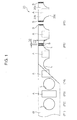
Fig. 1] Fig. 1 is a process diagram for explaining a method of producing a disposable diaper using an ultrasonic welding device according to the present invention; - [
Fig. 2] Fig. 2 is a front-view diagram illustrating the schematic configuration of an ultrasonic welding device according to a first embodiment of the present invention, for carrying out the welding step illustrated inFig. 1 ; - [
Fig. 3] Fig. 3 is a cross-sectional diagram ofFig. 2 along line III-III; - [
Fig. 4] Fig. 4 is a cross-sectional diagram ofFig. 3 along line IV-IV; - [
Fig. 5] Fig. 5 is a front-view cross-sectional diagram of an anvil roller illustrated inFig. 4 ; and - [
Fig. 6] Fig. 6 is a diagram, corresponding toFig. 5 , illustrating an anvil roller of an ultrasonic welding device according to a second embodiment of the present invention. - The embodiments of the present invention are described hereinbelow by referring to the attached figures. The following embodiments are examples substantiating the present invention and do not limit the technical scope of the present invention.
- With reference to
Fig. 1 , adisposable diaper 20 includes, when worn, a frontabdominal section 20a disposed on the abdomen of the wearer, a reardorsal section 20b disposed on the buttocks of the wearer, and acrotch section 20c that extends from the frontabdominal section 20a, passing between the legs of the wearer, up to the reardorsal section 20b. - Both side edge portions of the front
abdominal section 20a and both side edge portions of the reardorsal section 20b are welded to each other by two weld sections S, in such a manner that the frontabdominal section 20a and the reardorsal section 20b are connected in the form of a ring. - A method of producing the
disposable diaper 20 will be explained next. - In the transport step P1, a sheet W that extends in a specific direction is transported along the length direction of the sheet W. In the explanation hereafter, the flow direction of the sheet W will be referred to as transversal direction, and the direction perpendicular to the transversal direction in
Fig. 1 will be referred to as longitudinal direction. - The sheet W has an inner sheet that faces the body surface of the wearer when the wearer wears the diaper, an outer sheet that faces away from the wearer when the wearer wears the diaper, and an elastic member that is sandwiched between the inner sheet and the outer sheet.
- The inner sheet is constituted by a nonwoven fabric sheet and/or a mesh sheet having liquid permeability. The outer sheet is constituted by a material, identical to that of the inner sheet, a polyethylene film, a polypropylene film, or a nonwoven fabric having water repellency and breathability.
- The elastic member is constituted by a sheet or thread made of polyurethane, natural rubber, or a thermoplastic resin.
- In the leg hole forming step P2, leg holes L are formed at a central position of the sheet W in the longitudinal direction.
- Each region between the two leg holes L in the sheet W is a portion corresponding to the
crotch section 20c. The positions on both sides of each portion in the sheet W corresponding to thecrotch section 20c, in the longitudinal direction, correspond herein to the frontabdominal section 20a and the reardorsal section 20b, respectively. - In the absorbent body bonding step P3, an absorbent body A is bonded at a position in the sheet W between the two leg holes L.
- The absorbent body A includes a permeable sheet having liquid permeability, a water-repellent sheet having water-repellency and breathability, and an absorbent core sandwiched between the permeable sheet and the water-repellent sheet.
- The permeable sheet is constituted by a nonwoven fabric sheet and/or a mesh sheet having liquid permeability. The water-repellent sheet is constituted by a polyethylene film, a polypropylene film, or a nonwoven fabric having water-repellency and breathability.
- The absorbent core is molded through layering of crushed pulp or crushed pulp mixed with a high water-absorbing polymer.
- A method is explained herein where the absorbent body A is bonded to the sheet W, but the absorbent core may be bonded in a state where the absorbent core is sandwiched between the inner sheet and the outer sheet of the sheet W. In this case, the inner sheet is constituted by a nonwoven fabric sheet and/or a mesh sheet having liquid permeability. The outer sheet is constituted by a polyethylene film, a polypropylene film, or a nonwoven fabric having water-repellency and breathability.
- In the fold-in-half step P4, the sheet W (continuous body) having the absorbent body A placed thereon is folded in half in the longitudinal direction. As a result, the portion of the sheet W corresponding to the front
abdominal section 20a and the portion corresponding to the reardorsal section 20b are overlapped on each other. - In the welding step P5, a portion of the folded sheet W corresponding to a side edge portion of the front
abdominal section 20a and the portion corresponding to a side edge portion of the reardorsal section 20b are ultrasonically welded. - In the welding step P5, specifically, two sites of the sheet W are ultrasonically welded simultaneously, with a spacing D2 including a predetermined cutting range as a range of cutting in the cutting step P6 described below.
- The two weld sections S are respectively formed over a welding range D1 in the longitudinal direction of a portion corresponding to a side edge portion of the front
abdominal section 20a, and a portion corresponding to a side edge portion of the reardorsal section 20b. - In the cutting step P6, the sheet W is cut along a respective cutting line that extends, in the longitudinal direction, between two weld sections S formed in the welding step P5. The sheet W (continuous body) is cut as a result into each
disposable diaper 20. - An explanation follows next, with reference to
Fig. 2 , on anultrasonic welding device 1, according to the first embodiment, that carries out the welding step P5. - The
ultrasonic welding device 1 is provided with anintroduction roller 2 that introduces the folded sheet W undergone the fold-in-half step P4; awelding drum 3 that welds the sheet W that is introduced by theintroduction roller 2; and a lead-outroller 4 that leads out the sheet W welded by thewelding drum 3. - The
welding drum 3 is provided with: a sheet holding drum (holding member) 5 that holds the sheet (object to be welded) W that is introduced by theintroduction roller 2; sixultrasonic horns 6 that are provided on thesheet holding drum 5; sixanvil units 7 for ultrasonically welding the sheet W between theultrasonic horns 6 andrespective anvil units 7; a cylindrical anvil holding drum 8 (seeFig. 3 ) that holds theanvil units 7; and a cam drum 9 (seeFig. 3 ) provided inside theanvil holding drum 8. - With reference to
Fig. 2 andFig. 3 , thesheet holding drum 5 can rotate about a rotation center C1 in a state where the sheet W is held on the outer peripheral surface of thesheet holding drum 5. Sixrecessed grooves 5a are formed equidistantly, about the rotation center C1, on thesheet holding drum 5. Therecessed grooves 5a open outward from thesheet holding drum 5 and extend along the rotation center C1. - The
ultrasonic horns 6 impart ultrasonic vibration to the sheet W that is held on thesheet holding drum 5. Specifically, theultrasonic horns 6 are provided in respectiverecessed grooves 5a, in such a manner that weldingsurfaces 6a of theultrasonic horns 6 come in contact, from inside, with the sheet W that is held on thesheet holding drum 5. - Each of the
anvil units 7 is provided at position identical to each of theultrasonic horns 6, about the rotation center C1. Theanvil units 7 have all the same configuration; hence, the configuration of just one ofanvil unit 7 will be explained, and a explanation of theother anvil units 7 will be omitted. -
Anvil unit 7 is provided with ananvil roller 10 for welding the sheet W between theultrasonic horn 6 and theanvil roller 10, and aholding mechanism 11 that holds rotatably theanvil roller 10, via arotary shaft 12a, in such a manner that theanvil roller 10 can be in rolling contact with the sheet W, in response to the displacement of theanvil roller 10 with respect to thesheet holding drum 5. - As illustrated in
Fig. 3 andFig. 4 , holdingmechanism 11 is provided with: abody section 12 that holds theanvil roller 10; acam protrusion 14 that extends from thebody section 12 toward the rotation center C1; and a pair of engagingprotrusions 15 that protrude from thebody section 12, in opposite orientations in a direction (left-right direction inFig. 4 ) perpendicular to thecam protrusion 14 and the rotation center C1, and that extend along the rotation center C1. - The
body section 12 is provided between a pair ofrails 17 that are standed on the outer peripheral surface of theanvil holding drum 8. In therails 17, engaging grooves which open toward counterpart rails 17 and which extend along the rotation center C1 are formed. The engagingprotrusions 15 of thebody section 12 engage with respectiveengaging grooves 17a in such a manner that the engagingprotrusions 15 can move along the rotation center C1, with respect toanvil holding drum 8. - The cylindrical
anvil holding drum 8 is provided withslits 16a that penetrate through the peripheral wall of the cylindricalanvil holding drum 8 and that extend along the rotation center C1. The cam protrusions 14 of thebody sections 12 are inserted into theanvil holding drum 8 viarespective slits 16a. - The
cam drum 9 is provided inside theanvil holding drum 8, and acam groove 9a is formed on the outer peripheral surface of thecam drum 9. The leading end sections of thecam protrusions 14 are inserted into thecam groove 9a. Thecam groove 9a guides thecam protrusions 14 in such a manner that theanvil units 7 move along the rotation center C1, in response to the rotation of theanvil holding drum 8 with respect to thecam drum 9. - The
sheet holding drum 5 and theanvil holding drum 8 are fixed to each other and rotate integrally about the rotation center C1. By contrast, the rotational position of thecam drum 9 is fixed, regardless of the rotation of thesheet holding drum 5 and theanvil holding drum 8. Therefore, thebody section 12 moves along the rotation center C1 in response to rotation of thesheet holding drum 5 and theanvil holding drum 8 about the rotation center C1. - That is, the holding
mechanism 11 and theanvil holding drum 8 correspond to a support mechanism that supports rotatably eachanvil roller 10, via therotary shaft 12a, in such a manner that theanvil roller 10 can move along the rotation center C1 with respect to thesheet holding drum 5, and theanvil roller 10 can be in rolling contact with the sheet W in response to the movement of theanvil roller 10 with respect to thesheet holding drum 5. - Specifically, in the
anvil unit 7 positioned lowermost inFig. 2 andFig. 3 , theanvil roller 10 is disposed at a separation position that is spaced apart from the sheet W held by thesheet holding drum 5. In this state, theanvil unit 7 moves in a direction of coming close to the sheet W along the rotation center C1, in response to the counter-clockwise rotation, inFig. 2 , of thesheet holding drum 5. - The
anvil roller 10 crosses over the sheet W when theanvil unit 7 is displaced up to the topmost position inFig. 2 and theFig. 3 . When thesheet holding drum 5 further rotates counter-clockwise from this state, theanvil unit 7 starts moving toward the separation position. - In the
ultrasonic welding device 1, thus, eachanvil roller 10 reciprocates over the sheet W, in the welding range D1 ofFig. 1 , within the range E1 ofFig. 2 . The sheet W is welded during this reciprocating movement. The position of eachanvil roller 10 with respect to thesheet holding drum 5 in the range E1 corresponds to a welding position. - The
anvil rollers 10 will be explained next with respect toFig. 3 andFig. 5 . - The
anvil rollers 10 are rollers made of metal (for instance, high-chromium steel, or high-carbon steel). - Each
anvil roller 10 is provided with a supportedsection 19 that is rotatably supported by the holdingmechanism 11, via therotary shaft 12a; an outerperipheral section 18 over which the sheet W can be welded between theultrasonic horn 6 and the outerperipheral section 18 during rolling contact with the sheet W; athin section 21 that is provided between the supportedsection 19 and the outerperipheral section 18; and twovibrationproof members 22 that are provided on thethin section 21. - The supported
section 19 is a boss portion that is rotatably supported, via therotary shaft 12a, by the holdingmechanism 11, in order to allow rolling contact of theanvil roller 10 with the sheet W in response to the movement of theanvil roller 10 between the welding position and the separation position. A through-hole 19a for insertion of therotary shaft 12a is formed in the supportedsection 19. - The outer
peripheral section 18 has a welding surface over which the sheet W can be welded between theultrasonic horn 6 and the outerperipheral section 18 during rolling contact with the sheet W. Specifically, the outerperipheral section 18 has a pair ofwelding sections 18a that protrude outward, in the diameter direction of the outerperipheral section 18, and that extend over the entire circumference about therotary shaft 12a. The spacing between thewelding sections 18a corresponds to the spacing D2 of the weld section S inFig. 1 . That is, the outer peripheral surface of thewelding sections 18a corresponds to the welding surface over which the sheet W is welded between thewelding sections 18a and theultrasonic horn 6. - The
thin section 21 is a portion that is formed through recessing of theanvil roller 10 from both sides in the axial direction of therotary shaft 12a. - A thickness dimension D4 of the
thin section 21, in the axial direction of therotary shaft 12a, is smaller than a thickness dimension D5 of the supportedsection 19 and a thickness dimension D3 of the outerperipheral section 18. The thickness dimension D5 of the supportedsection 19 is smaller than the thickness dimension D3 of the outerperipheral section 18. - As a result, the weight of the
anvil roller 10 can be reduced as compared with a cylindrical anvil roller having just the through-hole 19a alone formed therein. - The
thin section 21 is provided over the entire circumference about therotary shaft 12a. - The
vibrationproof members 22 are formed of a material that can deform elastically (for instance, a rubber material such as silicon rubber or synthetic rubber, or a synthetic resin material). By deforming elastically, thevibrationproof members 22 reduce the vibration of theanvil roller 10. - The two
vibrationproof members 22 are bonded to two respective reverse faces 18b, with respect to the welding surface of the outerperipheral section 18, as defined by thethin section 21. The reverse faces 18b are tilted by an angle of 20° with respect to the axis of therotary shaft 12a, and thevibrationproof members 22 are provided over the entire circumference of the reverse faces 18b about therotary shaft 12a. - The
vibrationproof members 22 are provided only over part of thethin section 21. That is, thevibrationproof members 22 are formed over a given thickness in the entire circumference about therotary shaft 12a. A clearance is thus formed between thevibrationproof members 22 and the supportedsection 19. - As explained above, vibration in the
anvil roller 10 can be suppressed by thevibrationproof members 22 that are provided on thethin section 21. Accordingly, it becomes possible to reduce the weight of theanvil roller 10, through formation of thethin section 21, and, at the same time, to prevent the occurrence of noise that accompanies this reduction in weight. - The following effects can be obtained according to the above embodiment.
- According to the above embodiments, the
vibrationproof members 22 are provided on the reverse faces 18b with respect to the welding surface (outer peripheral surface of thewelding sections 18a) that receives ultrasonic vibration from theultrasonic horn 6. As a result, vibration of theanvil roller 10 can be suppressed efficiently at a position in the immediate vicinity of a vibration source. - According to the above embodiment, the
thin section 21 is provided over the entire circumference about therotary shaft 12a; as a result, the weight of theanvil roller 10 about therotary shaft 12a is equalized, and the rotational stability of theanvil roller 10 can be increased thereby. - Therefore, the above embodiment allows reducing, more reliably, generation of noise due to vibration of the
anvil roller 10, thanks to of the noise reduction effect derived from the rotational stability of theanvil roller 10, and the noise reduction effect derived from thevibrationproof members 22 that are provided over the entire circumference about therotary shaft 12a. - According to the above embodiment, the
vibrationproof members 22 are provided only over part of thethin section 21; accordingly, this allows suppressing an increase in the weight of theanvil roller 10 caused by an excessively large vibrationproof member. - According to the above embodiment, the thickness dimension D5 of the supported
section 19 is greater than the thickness dimension D4 of thethin section 21. Accordingly, the strength of the supportedsection 19 that is supported by therotary shaft 12a can be secured, while reducing the weight of theanvil roller 10 thanks to thethin section 21. - By setting the thickness dimension D5 of the supported
section 19 to be smaller than the thickness dimension D3 of the outerperipheral section 18, it becomes possible to reduce the weight of theanvil roller 10 while securing the necessary strength in the supportedsection 19. - The
anvil roller 10 of an ultrasonic welding device according to a second embodiment of the present invention will be explained next with reference toFig. 6 . Portions identical to those in the first embodiment will be denoted by the same reference symbols, and an explanation thereof will be omitted. - The
anvil roller 10 according to the second embodiment is provided with arounded section 18c that is formed between the outerperipheral section 18 and thethin section 21, and arounded section 21a that is formed between thethin section 21 and the supportedsection 19. - The
rounded sections rotary shaft 12a (seeFig. 3 ). - The outer
peripheral section 18 and the supportedsection 19 are connected to thethin section 21 via therounded sections anvil roller 10 between thethin section 21 and the outerperipheral section 18, and between thethin section 21 and the supportedsection 19, can be suppressed as a result. - Therefore, it becomes possible to suppress concentration of stress at the boundary portions between the
thin section 21 and the outerperipheral section 18, and between thethin section 21 and the supportedsection 19, upon application of ultrasonic vibration from theultrasonic horn 6 to theanvil roller 10. The fatigue strength of theanvil roller 10 can be enhanced as a result. - Herein there may be provided just one from among the
rounded sections - In the
anvil roller 10 according to the second embodiment, thevibrationproof members 22 are provided so as to be in close contact with the entire surface of therounded section 18c. In thevibrationproof members 22,inner surfaces 22a that face toward the supportedsection 19 are tilted by an angle of 20° with respect to the axis of therotary shaft 12a, as in the first embodiment. - In the above embodiments, the
vibrationproof members 22 are provided only over part of thethin section 21, but thevibrationproof members 22 may be provided over the entire range of thethin section 21. For instance, thevibrationproof members 22 can be filled up into thethin section 21. - In the above embodiments,
anvil rollers 10 have been explained that have the welding surface (welding sections 18a) provided over a 360° area about therotary shaft 12a, but the formation area of the welding surface can be set to less than 360° about therotary shaft 12a. - Specifically, the formation area (angle) of the welding surface can be set to have a circumferential length that exceeds the welding range D1 (
Fig. 1 ) of the sheet W. For instance, a semi-circular anvil roller can be used herein. - Using
circular anvil rollers 10 having a circumferential length that exceeds the welding range D1 of the sheet W, as in the above embodiments, has the following advantage. The frequency of replacement of theanvil roller 10, in a case where, for instance, part of the welding surface of theanvil roller 10 is damaged, can be reduced through adjustment of the mounting position of theanvil roller 10 in such a manner that welding can be carried out using a portion other than the damaged portion. - The specific embodiments described above include an invention having the following features.
- In order to solve the above problems, the inventors of the present application conceived of an invention pertaining to an anvil roller in which a thin section is formed between an outer peripheral section having a welding surface and a supported section that is supported by a rotary shaft, the thickness of the thin section being smaller than the thickness of the outer peripheral section.
- When the weight of the anvil roller is thus reduced through formation of the thin section, however, the natural frequency of the anvil roller increases, and a new problem arises thereupon, namely the occurrence of noise derived from resonance of the anvil roller when the anvil roller receives ultrasonic vibration from the ultrasonic horn.
- In order to solve this new problem, therefore, the present invention provides an anvil roller, used in an ultrasonic welding device that includes: a holding member that holds an object to be welded; an ultrasonic horn that applies ultrasonic vibration to the object to be welded held by the holding member; an anvil roller for welding the object to be welded, between the ultrasonic horn and the anvil roller; and a support mechanism that supports the anvil roller via a rotary shaft in such a manner that the anvil roller can move with respect to the holding member, and that the anvil roller can come into rolling contact with the object to be welded in response to the movement of the anvil roller with respect to the holding member, the anvil roller including: a supported section that is rotatably supported by the holding mechanism via the rotary shaft; an outer peripheral section having a welding surface over which the object to be welded can be welded between the ultrasonic horn and the outer peripheral section during rolling contact with the object to be welded; a thin section that is formed between the supported section and the outer peripheral section in such a manner that the thickness of the thin section is smaller than the thickness of the outer peripheral section in an axial direction of the rotary shaft; and a vibrationproof member provided on the thin section.
- According to the present invention, vibration occurring in the anvil roller can be suppressed by the vibrationproof member that is provided on the thin section. Accordingly, it becomes possible to reduce the weight of the anvil roller, through formation of the thin section, and, at the same time, to prevent the occurrence of noise that accompanies this reduction in weight.
- In the anvil roller, preferably, the vibrationproof member is provided on a reverse face, with respect to the welding surface, of the outer peripheral section, as defined by the thin section.
- In this aspect, the vibrationproof member is provided on the reverse face with respect to the welding surface that receives the ultrasonic vibration from the ultrasonic horn. Accordingly, vibration of the anvil roller can be suppressed efficiently at a position in the immediate vicinity of a vibration source.
- In the anvil roller, preferably, the thin section is provided over the entire circumference about the rotary shaft, and the vibrationproof member is provided over the entire circumference of the reverse face about the rotary shaft.
- In this aspect, the thin section is provided over the entire circumference about the rotary shaft; as a result, the weight of the anvil roller about the rotary shaft is equalized, and the rotational stability of the anvil roller can be increased thereby.
- Therefore, the above aspect allows reducing generation of noise due to vibration of the anvil roller more reliably, by virtue of the noise reduction effect derived from the rotational stability of the anvil roller, and the noise reduction effect derived from the vibrationproof member that is provided over the entire circumference about the rotary shaft.
- The vibrationproof member can be filled up into the entirety of a groove of the anvil roller that is defined by the thin section, but, preferably, the vibrationproof member is provided only over part of the thin section.
- This aspect allows suppressing an increase in the weight of the anvil roller caused by an excessively large vibrationproof member.
- In the anvil roller, preferably, the thickness of the supported section is greater than the thickness of the thin section in the axial direction of the rotary shaft.
- In this aspect, the strength of the supported section that is supported by the rotary shaft can be secured, while reducing the weight of the anvil roller by virtue of the thin section.
- By setting the thickness of the supported section to be smaller than the thickness of the outer peripheral section, it becomes possible to reduce the weight of the anvil roller while securing the necessary strength in the supported section.
- The present invention further provides an ultrasonic welding device that is provided with: a holding member that holds an object to be welded; an ultrasonic horn that applies ultrasonic vibration to the object to be welded held by the holding member; the anvil roller for welding the object to be welded, between the ultrasonic horn and the anvil roller; and a support mechanism that supports the anvil roller via a rotary shaft in such a manner that the anvil roller can move with respect to the holding member, and that the anvil roller can come into rolling contact with the object to be welded in response to the movement of the anvil roller with respect to the holding member.
Claims (7)
- An anvil roller, used in an ultrasonic welding device that includes: a holding member that holds an object to be welded; an ultrasonic horn that applies ultrasonic vibration to the object to be welded held by the holding member; an anvil roller for welding the object to be welded between the ultrasonic horn and the anvil roller; and a support mechanism that supports the anvil roller via a rotary shaft in such a manner that the anvil roller can move with respect to the holding member, and that the anvil roller can come into rolling contact with the object to be welded in response to the movement of the anvil roller with respect to the holding member, the anvil roller comprising:a supported section that is rotatably supported by the holding mechanism via the rotary shaft;an outer peripheral section having a welding surface over which the object to be welded can be welded between the ultrasonic horn and the outer peripheral section during rolling contact with the object to be welded;a thin section that is formed between the supported section and the outer peripheral section in such a manner that the thickness of the thin section is smaller than the thickness of the outer peripheral section in an axial direction of the rotary shaft; anda vibrationproof member provided on the thin section.
- The anvil roller according to claim 1, wherein the vibrationproof member is provided on a reverse face, with respect to the welding surface, of the outer peripheral section, as defined by the thin section.
- The anvil roller according to claim 2,
wherein the thin section is provided over the entire circumference about the rotary shaft, and
the vibrationproof member is provided over the entire circumference of the reverse face about the rotary shaft. - The anvil roller according to claim 2 or 3, wherein the vibrationproof member is provided only over part of the thin section.
- The anvil roller according to any one of claims 1 to 4, wherein the thickness of the supported section is greater than the thickness of the thin section in the axial direction of the rotary shaft.
- The anvil roller according to claim 5, wherein the thickness of the supported section is smaller than the thickness of the outer peripheral section.
- An ultrasonic welding device, comprising:a holding member that holds an object to be welded;an ultrasonic horn that applies ultrasonic vibration to the object to be welded held by the holding member;the anvil roller according to any one of claims 1 to 6, for welding the object to be welded, between the ultrasonic horn and the anvil roller; anda support mechanism that supports the anvil roller via a rotary shaft in such a manner that the anvil roller can move with respect to the holding member, and that the anvil roller can come into rolling contact with the object to be welded in response to the movement of the anvil roller with respect to the holding member.
Applications Claiming Priority (2)
| Application Number | Priority Date | Filing Date | Title |
|---|---|---|---|
| JP2013125942 | 2013-06-14 | ||
| PCT/JP2014/065807 WO2014200103A1 (en) | 2013-06-14 | 2014-06-13 | Anvil roller and ultrasonic welding device provided therewith |
Publications (3)
| Publication Number | Publication Date |
|---|---|
| EP2990179A1 true EP2990179A1 (en) | 2016-03-02 |
| EP2990179A4 EP2990179A4 (en) | 2016-12-28 |
| EP2990179B1 EP2990179B1 (en) | 2019-08-07 |
Family
ID=52022388
Family Applications (1)
| Application Number | Title | Priority Date | Filing Date |
|---|---|---|---|
| EP14810125.6A Active EP2990179B1 (en) | 2013-06-14 | 2014-06-13 | Anvil roller and ultrasonic welding device provided therewith |
Country Status (7)
| Country | Link |
|---|---|
| US (1) | US9333705B1 (en) |
| EP (1) | EP2990179B1 (en) |
| JP (1) | JP6343280B2 (en) |
| CN (1) | CN108064199B (en) |
| BR (1) | BR112015031085B1 (en) |
| MY (1) | MY184079A (en) |
| WO (1) | WO2014200103A1 (en) |
Families Citing this family (5)
| Publication number | Priority date | Publication date | Assignee | Title |
|---|---|---|---|---|
| KR101836754B1 (en) * | 2013-12-26 | 2018-03-08 | 가부시키가이샤 즈이코 | Ultrasonic welding device |
| BR112016015004B1 (en) * | 2013-12-26 | 2021-01-05 | Zuiko Corporation | ultrasonic welding device |
| CN107530203B (en) * | 2015-05-04 | 2021-11-12 | Gdm股份公司 | Unit for forming absorbent sanitary articles and method for manufacturing absorbent sanitary articles |
| US10919106B2 (en) | 2017-06-09 | 2021-02-16 | General Electric Company | Ultrasonic welding of annular components |
| US11919253B2 (en) * | 2022-07-21 | 2024-03-05 | Rohr, Inc. | Welding assembly and method using separately actuatable rams |
Family Cites Families (13)
| Publication number | Priority date | Publication date | Assignee | Title |
|---|---|---|---|---|
| JPS5257497Y2 (en) * | 1971-12-21 | 1977-12-27 | ||
| US5096532A (en) | 1990-01-10 | 1992-03-17 | Kimberly-Clark Corporation | Ultrasonic rotary horn |
| US5087320A (en) | 1990-05-18 | 1992-02-11 | Kimberly-Clark Corporation | Ultrasonic rotary horn having improved end configuration |
| AU639554B2 (en) | 1990-05-18 | 1993-07-29 | Kimberly-Clark Worldwide, Inc. | Ultrasonic rotary horn |
| US5660657A (en) * | 1995-01-31 | 1997-08-26 | Kimberly-Clark Worldwide, Inc. | Composite method for fabricating garments |
| US5660679A (en) | 1995-01-31 | 1997-08-26 | Kimberly-Clark Worldwide, Inc. | Rotary sealing system |
| CN1179128A (en) * | 1995-01-31 | 1998-04-15 | 金伯利-克拉克环球有限公司 | Rotary sealing system |
| JP2001236074A (en) * | 2000-02-21 | 2001-08-31 | Hayakawa Rubber Co Ltd | Peeling type soundproof material, peeling type vibration damping material and method for using the same |
| WO2005080065A1 (en) * | 2004-02-25 | 2005-09-01 | Zuiko Corporation | Welding system of web |
| JP4592690B2 (en) * | 2004-04-30 | 2010-12-01 | 株式会社瑞光 | Welding equipment |
| ES2303247T3 (en) * | 2004-06-02 | 2008-08-01 | Ferag Ag | METHOD AND DEVICE FOR PACKING FLAT OBJECTS. |
| JP5591051B2 (en) * | 2010-09-30 | 2014-09-17 | ユニ・チャーム株式会社 | Apparatus and method for sonicating a web |
| JP2014097097A (en) * | 2012-11-13 | 2014-05-29 | Zuiko Corp | Web welding system, and web welding method |
-
2014
- 2014-06-13 JP JP2015522891A patent/JP6343280B2/en active Active
- 2014-06-13 WO PCT/JP2014/065807 patent/WO2014200103A1/en not_active Ceased
- 2014-06-13 US US14/893,596 patent/US9333705B1/en active Active
- 2014-06-13 MY MYPI2015704503A patent/MY184079A/en unknown
- 2014-06-13 BR BR112015031085-0A patent/BR112015031085B1/en active IP Right Grant
- 2014-06-13 CN CN201480033289.5A patent/CN108064199B/en active Active
- 2014-06-13 EP EP14810125.6A patent/EP2990179B1/en active Active
Also Published As
| Publication number | Publication date |
|---|---|
| US20160121542A1 (en) | 2016-05-05 |
| JPWO2014200103A1 (en) | 2017-02-23 |
| CN108064199A (en) | 2018-05-22 |
| EP2990179B1 (en) | 2019-08-07 |
| JP6343280B2 (en) | 2018-06-13 |
| MY184079A (en) | 2021-03-17 |
| US9333705B1 (en) | 2016-05-10 |
| BR112015031085A2 (en) | 2017-07-25 |
| BR112015031085B1 (en) | 2021-01-12 |
| EP2990179A4 (en) | 2016-12-28 |
| CN108064199B (en) | 2020-03-06 |
| WO2014200103A1 (en) | 2014-12-18 |
Similar Documents
| Publication | Publication Date | Title |
|---|---|---|
| EP2990179A1 (en) | Anvil roller and ultrasonic welding device provided therewith | |
| US9452565B2 (en) | Ultrasonic horn, welder provided therewith, and method of producing disposable diaper using ultrasonic horn | |
| EP2990180B1 (en) | Ultrasonic welding device and method of producing disposable diaper using same | |
| JP5385748B2 (en) | Disposable wearing article manufacturing equipment | |
| US10232596B2 (en) | Fixing device of plurality of sheets associated with absorbent article, and fixing method | |
| WO2010101281A1 (en) | Leg-surrounding opening forming apparatus and method of manufacturing absorbent article | |
| JP6420904B2 (en) | Conveying apparatus and method for producing disposable wearing article using the same | |
| US20180140471A1 (en) | Transport unit and method for manufacturing disposable wearing articles using same | |
| JP6295207B2 (en) | Disposable wearing article manufacturing method and welding apparatus used therefor | |
| JP6378835B2 (en) | Conveying apparatus and method for producing disposable wearing article using the same |
Legal Events
| Date | Code | Title | Description |
|---|---|---|---|
| PUAI | Public reference made under article 153(3) epc to a published international application that has entered the european phase |
Free format text: ORIGINAL CODE: 0009012 |
|
| 17P | Request for examination filed |
Effective date: 20151124 |
|
| AK | Designated contracting states |
Kind code of ref document: A1 Designated state(s): AL AT BE BG CH CY CZ DE DK EE ES FI FR GB GR HR HU IE IS IT LI LT LU LV MC MK MT NL NO PL PT RO RS SE SI SK SM TR |
|
| AX | Request for extension of the european patent |
Extension state: BA ME |
|
| DAX | Request for extension of the european patent (deleted) | ||
| A4 | Supplementary search report drawn up and despatched |
Effective date: 20161125 |
|
| RIC1 | Information provided on ipc code assigned before grant |
Ipc: B29C 65/08 20060101AFI20161121BHEP Ipc: A61F 13/15 20060101ALI20161121BHEP Ipc: B29L 31/48 20060101ALN20161121BHEP Ipc: A61F 13/49 20060101ALI20161121BHEP Ipc: B29C 65/78 20060101ALN20161121BHEP |
|
| RAP1 | Party data changed (applicant data changed or rights of an application transferred) |
Owner name: ZUIKO CORPORATION |
|
| GRAP | Despatch of communication of intention to grant a patent |
Free format text: ORIGINAL CODE: EPIDOSNIGR1 |
|
| STAA | Information on the status of an ep patent application or granted ep patent |
Free format text: STATUS: GRANT OF PATENT IS INTENDED |
|
| RIC1 | Information provided on ipc code assigned before grant |
Ipc: B29C 65/78 20060101ALN20190116BHEP Ipc: A61F 13/15 20060101ALI20190116BHEP Ipc: A61F 13/49 20060101ALI20190116BHEP Ipc: B29L 31/48 20060101ALN20190116BHEP Ipc: B29C 65/08 20060101AFI20190116BHEP |
|
| INTG | Intention to grant announced |
Effective date: 20190220 |
|
| GRAS | Grant fee paid |
Free format text: ORIGINAL CODE: EPIDOSNIGR3 |
|
| GRAA | (expected) grant |
Free format text: ORIGINAL CODE: 0009210 |
|
| STAA | Information on the status of an ep patent application or granted ep patent |
Free format text: STATUS: THE PATENT HAS BEEN GRANTED |
|
| AK | Designated contracting states |
Kind code of ref document: B1 Designated state(s): AL AT BE BG CH CY CZ DE DK EE ES FI FR GB GR HR HU IE IS IT LI LT LU LV MC MK MT NL NO PL PT RO RS SE SI SK SM TR |
|
| REG | Reference to a national code |
Ref country code: GB Ref legal event code: FG4D |
|
| REG | Reference to a national code |
Ref country code: CH Ref legal event code: EP Ref country code: AT Ref legal event code: REF Ref document number: 1163157 Country of ref document: AT Kind code of ref document: T Effective date: 20190815 |
|
| REG | Reference to a national code |
Ref country code: DE Ref legal event code: R096 Ref document number: 602014051418 Country of ref document: DE |
|
| REG | Reference to a national code |
Ref country code: IE Ref legal event code: FG4D |
|
| REG | Reference to a national code |
Ref country code: SE Ref legal event code: TRGR |
|
| REG | Reference to a national code |
Ref country code: NL Ref legal event code: FP |
|
| REG | Reference to a national code |
Ref country code: LT Ref legal event code: MG4D |
|
| PG25 | Lapsed in a contracting state [announced via postgrant information from national office to epo] |
Ref country code: LT Free format text: LAPSE BECAUSE OF FAILURE TO SUBMIT A TRANSLATION OF THE DESCRIPTION OR TO PAY THE FEE WITHIN THE PRESCRIBED TIME-LIMIT Effective date: 20190807 Ref country code: HR Free format text: LAPSE BECAUSE OF FAILURE TO SUBMIT A TRANSLATION OF THE DESCRIPTION OR TO PAY THE FEE WITHIN THE PRESCRIBED TIME-LIMIT Effective date: 20190807 Ref country code: BG Free format text: LAPSE BECAUSE OF FAILURE TO SUBMIT A TRANSLATION OF THE DESCRIPTION OR TO PAY THE FEE WITHIN THE PRESCRIBED TIME-LIMIT Effective date: 20191107 Ref country code: NO Free format text: LAPSE BECAUSE OF FAILURE TO SUBMIT A TRANSLATION OF THE DESCRIPTION OR TO PAY THE FEE WITHIN THE PRESCRIBED TIME-LIMIT Effective date: 20191107 Ref country code: FI Free format text: LAPSE BECAUSE OF FAILURE TO SUBMIT A TRANSLATION OF THE DESCRIPTION OR TO PAY THE FEE WITHIN THE PRESCRIBED TIME-LIMIT Effective date: 20190807 Ref country code: PT Free format text: LAPSE BECAUSE OF FAILURE TO SUBMIT A TRANSLATION OF THE DESCRIPTION OR TO PAY THE FEE WITHIN THE PRESCRIBED TIME-LIMIT Effective date: 20191209 |
|
| REG | Reference to a national code |
Ref country code: AT Ref legal event code: MK05 Ref document number: 1163157 Country of ref document: AT Kind code of ref document: T Effective date: 20190807 |
|
| PG25 | Lapsed in a contracting state [announced via postgrant information from national office to epo] |
Ref country code: RS Free format text: LAPSE BECAUSE OF FAILURE TO SUBMIT A TRANSLATION OF THE DESCRIPTION OR TO PAY THE FEE WITHIN THE PRESCRIBED TIME-LIMIT Effective date: 20190807 Ref country code: IS Free format text: LAPSE BECAUSE OF FAILURE TO SUBMIT A TRANSLATION OF THE DESCRIPTION OR TO PAY THE FEE WITHIN THE PRESCRIBED TIME-LIMIT Effective date: 20191207 Ref country code: GR Free format text: LAPSE BECAUSE OF FAILURE TO SUBMIT A TRANSLATION OF THE DESCRIPTION OR TO PAY THE FEE WITHIN THE PRESCRIBED TIME-LIMIT Effective date: 20191108 Ref country code: LV Free format text: LAPSE BECAUSE OF FAILURE TO SUBMIT A TRANSLATION OF THE DESCRIPTION OR TO PAY THE FEE WITHIN THE PRESCRIBED TIME-LIMIT Effective date: 20190807 Ref country code: AL Free format text: LAPSE BECAUSE OF FAILURE TO SUBMIT A TRANSLATION OF THE DESCRIPTION OR TO PAY THE FEE WITHIN THE PRESCRIBED TIME-LIMIT Effective date: 20190807 Ref country code: ES Free format text: LAPSE BECAUSE OF FAILURE TO SUBMIT A TRANSLATION OF THE DESCRIPTION OR TO PAY THE FEE WITHIN THE PRESCRIBED TIME-LIMIT Effective date: 20190807 |
|
| PG25 | Lapsed in a contracting state [announced via postgrant information from national office to epo] |
Ref country code: TR Free format text: LAPSE BECAUSE OF FAILURE TO SUBMIT A TRANSLATION OF THE DESCRIPTION OR TO PAY THE FEE WITHIN THE PRESCRIBED TIME-LIMIT Effective date: 20190807 |
|
| PG25 | Lapsed in a contracting state [announced via postgrant information from national office to epo] |
Ref country code: AT Free format text: LAPSE BECAUSE OF FAILURE TO SUBMIT A TRANSLATION OF THE DESCRIPTION OR TO PAY THE FEE WITHIN THE PRESCRIBED TIME-LIMIT Effective date: 20190807 Ref country code: DK Free format text: LAPSE BECAUSE OF FAILURE TO SUBMIT A TRANSLATION OF THE DESCRIPTION OR TO PAY THE FEE WITHIN THE PRESCRIBED TIME-LIMIT Effective date: 20190807 Ref country code: PL Free format text: LAPSE BECAUSE OF FAILURE TO SUBMIT A TRANSLATION OF THE DESCRIPTION OR TO PAY THE FEE WITHIN THE PRESCRIBED TIME-LIMIT Effective date: 20190807 Ref country code: RO Free format text: LAPSE BECAUSE OF FAILURE TO SUBMIT A TRANSLATION OF THE DESCRIPTION OR TO PAY THE FEE WITHIN THE PRESCRIBED TIME-LIMIT Effective date: 20190807 Ref country code: EE Free format text: LAPSE BECAUSE OF FAILURE TO SUBMIT A TRANSLATION OF THE DESCRIPTION OR TO PAY THE FEE WITHIN THE PRESCRIBED TIME-LIMIT Effective date: 20190807 |
|
| PG25 | Lapsed in a contracting state [announced via postgrant information from national office to epo] |
Ref country code: IS Free format text: LAPSE BECAUSE OF FAILURE TO SUBMIT A TRANSLATION OF THE DESCRIPTION OR TO PAY THE FEE WITHIN THE PRESCRIBED TIME-LIMIT Effective date: 20200224 Ref country code: SM Free format text: LAPSE BECAUSE OF FAILURE TO SUBMIT A TRANSLATION OF THE DESCRIPTION OR TO PAY THE FEE WITHIN THE PRESCRIBED TIME-LIMIT Effective date: 20190807 Ref country code: CZ Free format text: LAPSE BECAUSE OF FAILURE TO SUBMIT A TRANSLATION OF THE DESCRIPTION OR TO PAY THE FEE WITHIN THE PRESCRIBED TIME-LIMIT Effective date: 20190807 Ref country code: SK Free format text: LAPSE BECAUSE OF FAILURE TO SUBMIT A TRANSLATION OF THE DESCRIPTION OR TO PAY THE FEE WITHIN THE PRESCRIBED TIME-LIMIT Effective date: 20190807 |
|
| REG | Reference to a national code |
Ref country code: DE Ref legal event code: R097 Ref document number: 602014051418 Country of ref document: DE |
|
| PLBE | No opposition filed within time limit |
Free format text: ORIGINAL CODE: 0009261 |
|
| STAA | Information on the status of an ep patent application or granted ep patent |
Free format text: STATUS: NO OPPOSITION FILED WITHIN TIME LIMIT |
|
| PG2D | Information on lapse in contracting state deleted |
Ref country code: IS |
|
| 26N | No opposition filed |
Effective date: 20200603 |
|
| PG25 | Lapsed in a contracting state [announced via postgrant information from national office to epo] |
Ref country code: SI Free format text: LAPSE BECAUSE OF FAILURE TO SUBMIT A TRANSLATION OF THE DESCRIPTION OR TO PAY THE FEE WITHIN THE PRESCRIBED TIME-LIMIT Effective date: 20190807 |
|
| PG25 | Lapsed in a contracting state [announced via postgrant information from national office to epo] |
Ref country code: MC Free format text: LAPSE BECAUSE OF FAILURE TO SUBMIT A TRANSLATION OF THE DESCRIPTION OR TO PAY THE FEE WITHIN THE PRESCRIBED TIME-LIMIT Effective date: 20190807 |
|
| REG | Reference to a national code |
Ref country code: CH Ref legal event code: PL |
|
| PG25 | Lapsed in a contracting state [announced via postgrant information from national office to epo] |
Ref country code: LU Free format text: LAPSE BECAUSE OF NON-PAYMENT OF DUE FEES Effective date: 20200613 |
|
| REG | Reference to a national code |
Ref country code: BE Ref legal event code: MM Effective date: 20200630 |
|
| PG25 | Lapsed in a contracting state [announced via postgrant information from national office to epo] |
Ref country code: LI Free format text: LAPSE BECAUSE OF NON-PAYMENT OF DUE FEES Effective date: 20200630 Ref country code: IE Free format text: LAPSE BECAUSE OF NON-PAYMENT OF DUE FEES Effective date: 20200613 Ref country code: CH Free format text: LAPSE BECAUSE OF NON-PAYMENT OF DUE FEES Effective date: 20200630 |
|
| PG25 | Lapsed in a contracting state [announced via postgrant information from national office to epo] |
Ref country code: BE Free format text: LAPSE BECAUSE OF NON-PAYMENT OF DUE FEES Effective date: 20200630 |
|
| PGFP | Annual fee paid to national office [announced via postgrant information from national office to epo] |
Ref country code: GB Payment date: 20210625 Year of fee payment: 8 |
|
| PG25 | Lapsed in a contracting state [announced via postgrant information from national office to epo] |
Ref country code: MT Free format text: LAPSE BECAUSE OF FAILURE TO SUBMIT A TRANSLATION OF THE DESCRIPTION OR TO PAY THE FEE WITHIN THE PRESCRIBED TIME-LIMIT Effective date: 20190807 Ref country code: CY Free format text: LAPSE BECAUSE OF FAILURE TO SUBMIT A TRANSLATION OF THE DESCRIPTION OR TO PAY THE FEE WITHIN THE PRESCRIBED TIME-LIMIT Effective date: 20190807 |
|
| PG25 | Lapsed in a contracting state [announced via postgrant information from national office to epo] |
Ref country code: MK Free format text: LAPSE BECAUSE OF FAILURE TO SUBMIT A TRANSLATION OF THE DESCRIPTION OR TO PAY THE FEE WITHIN THE PRESCRIBED TIME-LIMIT Effective date: 20190807 |
|
| GBPC | Gb: european patent ceased through non-payment of renewal fee |
Effective date: 20220613 |
|
| PG25 | Lapsed in a contracting state [announced via postgrant information from national office to epo] |
Ref country code: GB Free format text: LAPSE BECAUSE OF NON-PAYMENT OF DUE FEES Effective date: 20220613 |
|
| P01 | Opt-out of the competence of the unified patent court (upc) registered |
Effective date: 20230621 |
|
| PGFP | Annual fee paid to national office [announced via postgrant information from national office to epo] |
Ref country code: NL Payment date: 20240619 Year of fee payment: 11 |
|
| PGFP | Annual fee paid to national office [announced via postgrant information from national office to epo] |
Ref country code: SE Payment date: 20240619 Year of fee payment: 11 |
|
| PGFP | Annual fee paid to national office [announced via postgrant information from national office to epo] |
Ref country code: DE Payment date: 20250618 Year of fee payment: 12 |
|
| PGFP | Annual fee paid to national office [announced via postgrant information from national office to epo] |
Ref country code: FR Payment date: 20250625 Year of fee payment: 12 |
|
| PGFP | Annual fee paid to national office [announced via postgrant information from national office to epo] |
Ref country code: IT Payment date: 20250624 Year of fee payment: 12 |
|
| REG | Reference to a national code |
Ref country code: SE Ref legal event code: EUG |
|
| REG | Reference to a national code |
Ref country code: NL Ref legal event code: MM Effective date: 20250701 |
|
| PG25 | Lapsed in a contracting state [announced via postgrant information from national office to epo] |
Ref country code: NL Free format text: LAPSE BECAUSE OF NON-PAYMENT OF DUE FEES Effective date: 20250701 |