EP2989963A1 - Stereoscopic endoscope system - Google Patents
Stereoscopic endoscope system Download PDFInfo
- Publication number
- EP2989963A1 EP2989963A1 EP14852731.0A EP14852731A EP2989963A1 EP 2989963 A1 EP2989963 A1 EP 2989963A1 EP 14852731 A EP14852731 A EP 14852731A EP 2989963 A1 EP2989963 A1 EP 2989963A1
- Authority
- EP
- European Patent Office
- Prior art keywords
- image
- section
- observation
- identification information
- monitor
- Prior art date
- Legal status (The legal status is an assumption and is not a legal conclusion. Google has not performed a legal analysis and makes no representation as to the accuracy of the status listed.)
- Withdrawn
Links
- 238000012937 correction Methods 0.000 claims abstract description 119
- 230000015654 memory Effects 0.000 claims abstract description 70
- 238000007689 inspection Methods 0.000 claims description 44
- 239000011521 glass Substances 0.000 claims description 43
- 238000004519 manufacturing process Methods 0.000 claims description 41
- 230000000007 visual effect Effects 0.000 claims description 25
- 230000007246 mechanism Effects 0.000 claims description 21
- 230000008859 change Effects 0.000 claims description 4
- 238000010586 diagram Methods 0.000 description 57
- 238000000034 method Methods 0.000 description 29
- 230000008569 process Effects 0.000 description 19
- 238000003780 insertion Methods 0.000 description 12
- 230000037431 insertion Effects 0.000 description 12
- 210000000683 abdominal cavity Anatomy 0.000 description 10
- 238000005286 illumination Methods 0.000 description 10
- 238000012790 confirmation Methods 0.000 description 8
- 230000003287 optical effect Effects 0.000 description 8
- 230000010287 polarization Effects 0.000 description 8
- 238000001514 detection method Methods 0.000 description 5
- 239000000758 substrate Substances 0.000 description 5
- 238000004364 calculation method Methods 0.000 description 4
- 230000007423 decrease Effects 0.000 description 4
- 230000000694 effects Effects 0.000 description 4
- 230000006870 function Effects 0.000 description 4
- 239000004973 liquid crystal related substance Substances 0.000 description 4
- 238000001839 endoscopy Methods 0.000 description 2
- 230000002401 inhibitory effect Effects 0.000 description 2
- 230000008707 rearrangement Effects 0.000 description 2
- 238000001356 surgical procedure Methods 0.000 description 2
- 230000003187 abdominal effect Effects 0.000 description 1
- 238000004458 analytical method Methods 0.000 description 1
- 238000003491 array Methods 0.000 description 1
- 208000003464 asthenopia Diseases 0.000 description 1
- 230000004888 barrier function Effects 0.000 description 1
- 238000004422 calculation algorithm Methods 0.000 description 1
- 238000006243 chemical reaction Methods 0.000 description 1
- 230000005484 gravity Effects 0.000 description 1
- 238000012986 modification Methods 0.000 description 1
- 230000004048 modification Effects 0.000 description 1
- 201000003152 motion sickness Diseases 0.000 description 1
- 239000013307 optical fiber Substances 0.000 description 1
- 238000007619 statistical method Methods 0.000 description 1
- 238000011179 visual inspection Methods 0.000 description 1
Images












Classifications
-
- A—HUMAN NECESSITIES
- A61—MEDICAL OR VETERINARY SCIENCE; HYGIENE
- A61B—DIAGNOSIS; SURGERY; IDENTIFICATION
- A61B1/00—Instruments for performing medical examinations of the interior of cavities or tubes of the body by visual or photographical inspection, e.g. endoscopes; Illuminating arrangements therefor
- A61B1/00163—Optical arrangements
- A61B1/00193—Optical arrangements adapted for stereoscopic vision
-
- A—HUMAN NECESSITIES
- A61—MEDICAL OR VETERINARY SCIENCE; HYGIENE
- A61B—DIAGNOSIS; SURGERY; IDENTIFICATION
- A61B1/00—Instruments for performing medical examinations of the interior of cavities or tubes of the body by visual or photographical inspection, e.g. endoscopes; Illuminating arrangements therefor
- A61B1/00002—Operational features of endoscopes
- A61B1/00004—Operational features of endoscopes characterised by electronic signal processing
- A61B1/00009—Operational features of endoscopes characterised by electronic signal processing of image signals during a use of endoscope
- A61B1/000095—Operational features of endoscopes characterised by electronic signal processing of image signals during a use of endoscope for image enhancement
-
- A—HUMAN NECESSITIES
- A61—MEDICAL OR VETERINARY SCIENCE; HYGIENE
- A61B—DIAGNOSIS; SURGERY; IDENTIFICATION
- A61B1/00—Instruments for performing medical examinations of the interior of cavities or tubes of the body by visual or photographical inspection, e.g. endoscopes; Illuminating arrangements therefor
- A61B1/00002—Operational features of endoscopes
- A61B1/00043—Operational features of endoscopes provided with output arrangements
- A61B1/00045—Display arrangement
-
- A—HUMAN NECESSITIES
- A61—MEDICAL OR VETERINARY SCIENCE; HYGIENE
- A61B—DIAGNOSIS; SURGERY; IDENTIFICATION
- A61B1/00—Instruments for performing medical examinations of the interior of cavities or tubes of the body by visual or photographical inspection, e.g. endoscopes; Illuminating arrangements therefor
- A61B1/00163—Optical arrangements
- A61B1/00194—Optical arrangements adapted for three-dimensional imaging
-
- G—PHYSICS
- G02—OPTICS
- G02B—OPTICAL ELEMENTS, SYSTEMS OR APPARATUS
- G02B23/00—Telescopes, e.g. binoculars; Periscopes; Instruments for viewing the inside of hollow bodies; Viewfinders; Optical aiming or sighting devices
- G02B23/24—Instruments or systems for viewing the inside of hollow bodies, e.g. fibrescopes
- G02B23/2407—Optical details
- G02B23/2415—Stereoscopic endoscopes
-
- H—ELECTRICITY
- H04—ELECTRIC COMMUNICATION TECHNIQUE
- H04N—PICTORIAL COMMUNICATION, e.g. TELEVISION
- H04N13/00—Stereoscopic video systems; Multi-view video systems; Details thereof
- H04N13/10—Processing, recording or transmission of stereoscopic or multi-view image signals
- H04N13/106—Processing image signals
- H04N13/139—Format conversion, e.g. of frame-rate or size
-
- H—ELECTRICITY
- H04—ELECTRIC COMMUNICATION TECHNIQUE
- H04N—PICTORIAL COMMUNICATION, e.g. TELEVISION
- H04N13/00—Stereoscopic video systems; Multi-view video systems; Details thereof
- H04N13/10—Processing, recording or transmission of stereoscopic or multi-view image signals
- H04N13/106—Processing image signals
- H04N13/158—Switching image signals
-
- H—ELECTRICITY
- H04—ELECTRIC COMMUNICATION TECHNIQUE
- H04N—PICTORIAL COMMUNICATION, e.g. TELEVISION
- H04N13/00—Stereoscopic video systems; Multi-view video systems; Details thereof
- H04N13/20—Image signal generators
- H04N13/286—Image signal generators having separate monoscopic and stereoscopic modes
-
- H—ELECTRICITY
- H04—ELECTRIC COMMUNICATION TECHNIQUE
- H04N—PICTORIAL COMMUNICATION, e.g. TELEVISION
- H04N13/00—Stereoscopic video systems; Multi-view video systems; Details thereof
- H04N13/30—Image reproducers
- H04N13/332—Displays for viewing with the aid of special glasses or head-mounted displays [HMD]
-
- H—ELECTRICITY
- H04—ELECTRIC COMMUNICATION TECHNIQUE
- H04N—PICTORIAL COMMUNICATION, e.g. TELEVISION
- H04N13/00—Stereoscopic video systems; Multi-view video systems; Details thereof
- H04N13/30—Image reproducers
- H04N13/366—Image reproducers using viewer tracking
- H04N13/368—Image reproducers using viewer tracking for two or more viewers
-
- A—HUMAN NECESSITIES
- A61—MEDICAL OR VETERINARY SCIENCE; HYGIENE
- A61B—DIAGNOSIS; SURGERY; IDENTIFICATION
- A61B1/00—Instruments for performing medical examinations of the interior of cavities or tubes of the body by visual or photographical inspection, e.g. endoscopes; Illuminating arrangements therefor
- A61B1/04—Instruments for performing medical examinations of the interior of cavities or tubes of the body by visual or photographical inspection, e.g. endoscopes; Illuminating arrangements therefor combined with photographic or television appliances
-
- G—PHYSICS
- G03—PHOTOGRAPHY; CINEMATOGRAPHY; ANALOGOUS TECHNIQUES USING WAVES OTHER THAN OPTICAL WAVES; ELECTROGRAPHY; HOLOGRAPHY
- G03B—APPARATUS OR ARRANGEMENTS FOR TAKING PHOTOGRAPHS OR FOR PROJECTING OR VIEWING THEM; APPARATUS OR ARRANGEMENTS EMPLOYING ANALOGOUS TECHNIQUES USING WAVES OTHER THAN OPTICAL WAVES; ACCESSORIES THEREFOR
- G03B35/00—Stereoscopic photography
- G03B35/08—Stereoscopic photography by simultaneous recording
-
- H—ELECTRICITY
- H04—ELECTRIC COMMUNICATION TECHNIQUE
- H04N—PICTORIAL COMMUNICATION, e.g. TELEVISION
- H04N7/00—Television systems
- H04N7/18—Closed-circuit television [CCTV] systems, i.e. systems in which the video signal is not broadcast
Definitions
- the present invention relates to a stereoscopic endoscope system which includes a stereoscopic endoscope having a right image pickup section and a left image pickup section.
- a general endoscope apparatus is a so-called 2D endoscope apparatus for observing a subject site as a planar image.
- the planar image does not give a perspective feeling, a stereoscopic effect cannot be obtained when subtle unevenness or the like on a surface of a body cavity wall is observed as a specific example of the subject site.
- a conventional stereoscopic endoscope apparatus is adapted to, for example, form object images with two objective optical systems having a parallax which are provided at a distal end portion, transmit the object images to an eyepiece portion at a rear end portion via a pair of relay optical systems and a pair of eyepiece optical systems, and perform megascopic observation or image pickup by a pair of TV cameras.
- a second embodiment of Japanese Patent Application Laid-Open Publication No. 2004-222937 describes a stereoscopic endoscope apparatus which is provided with a right image-forming optical system, a right CCD, an ID memory for outputting a right identification signal, a left image-forming optical system, a left CCD, an ID memory for outputting a left identification signal, and a rearrangement apparatus to which right and left video signals and identification signals are inputted, wherein the rearrangement apparatus outputs a right video signal and a left video signal to odd and even lines of a display device, respectively, based on the identification signals.
- the display device is such that polarizing plates with polarization directions different from each other by 90 degrees are attached on the odd lines and the even lines, respectively. Therefore, it is possible to three-dimensionally observe an image by observing the display device via a pair of polarizing glasses having a right lens in a polarization direction capable of causing video transmitted through the odd lines to be transmitted and a left lens in a polarization direction capable of causing video transmitted through the even lines to be transmitted.
- a first embodiment of the official gazette describes a technique in which right video signals and left video signals are sequentially displayed to be stereoscopically observed via a pair of liquid crystal shutter glasses.
- Japanese Patent Application Laid-Open Publication No. 10-126814 describes a technique in which a field judging circuit for judging whether each field is for a right eye or for a left eye, and an adding circuit for adding a predetermined display signal to a recording portion in at least one of a judged right eye field and a judged left eye field are provided.
- Japanese Patent Application Laid-Open Publication No. 2005-223495 describes a technique in which three-dimensional video displaying means provided with a display surface on which left eye pixels and right eye pixels are alternately arrayed and a parallax barrier which arrays light transmitting areas and light shielding areas alternately according to the array of the right/left eye pixels to generate a parallax, and viewing position confirmation information displaying means for displaying viewing position confirmation information for a left eye and viewing position confirmation information for a right eye within a left half of the display surface and within a right half of the display surface, respectively, are provided so that an observer can determine an appropriate viewing position based on the viewing position confirmation information at time of viewing video.
- Fig. 32 is a block diagram showing a configuration in which a stereoscopic endoscope in which right and left image pickup sections and right and left memories are reversely connected is observed on a 3D monitor.
- a stereoscopic endoscope 101 is provided with: an R image pickup section 112r and an R output section 115r which are arranged on a right side of an endoscope body 111; an L image pickup section 1121 and an L output section 1151 which are arranged on a left side of the endoscope body 111; an R signal line 113r extended from the R image pickup section 112r; an L signal line 1131 extended from the L image pickup section 1121; an R memory 114r which stores R correction information for correcting a right eye image, and an L memory 1141 which stores L correction information for correcting a left eye image.
- the R image pickup section 112r and the L image pickup section 1121 are accurately positioned and assembled so that a right eye image and a left eye image for constituting a stereoscopic image can be acquired, respectively.
- positioning at a pixel pitch level is difficult. Therefore, correction information for cutting out a right eye image acquired from the R image pickup section 112r and a left eye image acquired from the L image pickup section 1121 and performing positioning so that a stereoscopic image can be accurately configured is recorded in each of the R memory 114r and the L memory 1141.
- a 3D monitor 105 is adapted so that an image outputted from the R output section 115r of the stereoscopic endoscope and an image outputted from the L output section 1151 of the stereoscopic endoscope are inputted as a right eye image and a left eye image, respectively, to display a stereoscopic image.
- a right eye image corrected with L correction information is outputted from the L output section 1151 and displayed on the 3D monitor 105 as a left eye image
- a left eye image corrected with R correction information is outputted from the R output section 115r and displayed on the 3D monitor 105 as a right eye image.
- Fig. 33 is a block diagram showing a configuration in which a manufacturing inspection of the stereoscopic endoscope shown in Fig. 32 is performed with use of a 2D monitor.
- the 2D monitor 103 is used by being connected to one of the output sections of the stereoscopic endoscope 101. In the example shown in Fig. 33 , the 2D monitor 103 is connected to the L output section 151.
- a finger is inserted in an image pickup range of only the L image pickup section 1121 to confirm whether the finger is displayed on the 2D monitor 103.
- an incorrect connection state as shown in Fig. 33 , since it is a right eye image picked up by the R image pickup section 112r that is outputted from the L output section 1151, the finger is not observed on the 2D monitor 103, and it can be detected that the L image pickup section 1121 is not connected to the L output section 1151. Therefore, it is possible to confirm the connection state of the R signal line 113r and the L signal line 1131 again and return the connection state to a correct connection state.
- a right eye image should be corrected with R correction information
- a left eye image should be corrected with L correction information.
- the R correction information and the L correction information are reversely stored in the memories. Therefore, the R image pickup section 112r is connected to the L memory 1141 and the R output section 115r, and the L image pickup section 1121 is connected to the R memory 114r and the L output section 1151.
- the present invention has been made in view of the above situation, and its object is to provide a stereoscopic endoscope system making it possible to easily confirm whether there is a right/left mistake in manufacture of a stereoscopic endoscope.
- a stereoscopic endoscope system is a stereoscopic endoscope system comprising a stereoscopic endoscope, the stereoscopic endoscope system comprising: the stereoscopic endoscope comprising: an endoscope body; a right image pickup section provided on a right side of the endoscope body and acquiring a right eye image; a left image pickup section provided on a left side of the endoscope body and acquiring a left eye image; a right memory associated with one of the right image pickup section and the left image pickup section and storing correction information for right for correcting the right eye image so that the right eye image is for stereoscopy, and right identification information for identifying that what is stored is the correction information for right; a left memory associated with another of the right image pickup section and the left image pickup section and storing correction information for left for correcting the left eye image so that the left eye image is for stereoscopy, and left identification information for identifying that what is stored is the correction information for left; a right output
- Figs. 1 to 31 show a first embodiment of the present invention
- Fig. 1 is a block diagram showing a configuration of a stereoscopic endoscope system in which right and left connections are incorrectly made at time of manufacture.
- the stereoscopic endoscope system of the present embodiment is provided with a stereoscopic endoscope 1, an identification information combining section 2 and a 2D monitor 3.
- the stereoscopic endoscope 1 has an endoscope body 11, an R image pickup section 12r, which is a right image pickup section, an L image pickup section 121, which is a left image pickup section, an R signal line 13r, which is a right signal line extended from the R image pickup section 12r, an L signal line 131, which is a left signal line extended from the L image pickup section 121, an R memory 14r, which is a right memory, an L memory 141, which is a left memory, an R output section 15r, which is a right output section, and an L output section 151, which is a left output section.
- R right or a right eye is indicated by R
- left or a left eye is indicated by L below.
- the R image pickup section 12r is provided on a right side of a distal end of the endoscope body 11 to acquire a right eye image.
- the L image pickup section 121 is provided on a left side of the distal end of the endoscope body 11 to acquire a left eye image.
- an image pickup section incorporated on a right side of the endoscope body 11 becomes the R image pickup section 12r
- an image pickup section incorporated on a left side of the endoscope body 11 becomes the L image pickup section 121.
- the right and left image pickup sections can be identified from incorporated appearances, and it does not happen that the right and left image pickup sections are reversely incorporated relative to the endoscope body 11 (that is, it does not happen that the L image pickup section 121 is incorporated on the right side of the endoscope body 11, and it does not happen that the R image pickup section 12r is incorporated on the left side of the endoscope body 11).
- the R memory 14r is associated with one of the R image pickup section 12r and the L image pickup section 121, and stores R correction information, which is correction information for right for correcting a right eye image so that the right eye image is for stereoscopy, and R correction identification information, which is right identification information for identifying that what the R memory 14r stores is the R correction information.
- the R correction information is correction information for cutting out a right eye image acquired from the R image pickup section 12r and performing positioning so that a stereoscopic image can be accurately configured.
- the L memory 141 is associated with the other of the R image pickup section 12r and the L image pickup section 121, and stores L correction information, which is correction information for left for correcting a left eye image so that the left eye image is for stereoscopy, and L correction identification information, which is left identification information for identifying that what the L memory 141 stores is the L correction information.
- the L correction information is correction information for cutting out a left eye image acquired from the L image pickup section 121 and performing positioning so that a stereoscopic image can be accurately configured.
- R image pickup section 12r or the L image pickup section 121 is directly connected and associated with the R memory 14r or the L memory 141 is shown in the present embodiment, they do not have to be directly connected. More generally, an image pickup section (12r or 121) which has picked up an image outputted from one of the R output section 15r and the L output section 151 and a memory (14r or 141) which stores correction information outputted from the same one output section are in a relationship of being mutually associated, and, similarly, an image pickup section (121 or 12r) which has picked up an image outputted from the other of the R output section 15r and the L output section 151 and a memory (141 or 14r) which stores correction information outputted from the other output section are in a relationship of being mutually associated.
- the R output section 15r is provided on the right side of the endoscope body 11, and outputs one of a first identification information/image set constituted by a right eye image and one of the right identification information and the left identification information which is associated with the R image pickup section 12r and a second identification information/image set constituted by a left eye image and the other of the right identification information and the left identification information which is associated with the L image pickup section 121 at the time of a manufacturing inspection.
- the L output section 151 is provided on the left side of the endoscope body 11, and outputs the other of the first identification information/image set and the second identification information/image set at the time of the manufacturing inspection.
- the identification information combining section 2 can perform image combination of an image and identification information of an identification information/image set inputted from the R output section 15r to output a combined image as a right output image, and can perform image combination of an image and identification information of an identification information/image set inputted from the L output section 151 to output a combined image as a left output image.
- the 2D monitor 3 is a display device which displays a two-dimensional image.
- the 2D monitor 3 is connected to the identification information combining section 2 such that at least one of a right output image and a left output image can be inputted, and displays a right output image, a left output image, or right and left output images inputted.
- Fig. 1 shows an example in which the R image pickup section 12r is connected to the R output section 15r, being associated with the L memory 141, and the L image pickup section 121 is connected to the L output section 151, being associated with the R memory 14r (that is, an example in which correct assembly is not established).
- the R signal line 13r extended from the R image pickup section 12r is connected to the L memory 141 and furthermore connected to the R output section 15r. Further, the L signal line 131 extended from the L image pickup section 121 is connected to the R memory 14r and furthermore connected to the L output section 151.
- the identification information combining section 2 and the 2D monitor 3 are connected to the L output section 151.
- an image and identification information combined with the image are to be displayed on the 2D monitor 3.
- Fig. 2 is a diagram showing a more specific configuration of the stereoscopic endoscope 1 in which right and left connections are incorrectly made.
- the R image pickup section 12r and the L image pickup section 121 are each provided with an objective optical system 12a, and an image pickup device 12b which performs photoelectric conversion of an optical image formed by the objective optical system 12a to output an image.
- the R signal line 13r and the L signal line 131 are connected, for example, to one face and the other face on a distal end side of a substrate 19, respectively, and memories are implemented on the one face and the other face of the substrate 19.
- L correction information and L correction identification information being stored into the memory implemented on one face of the substrate 19, the memory becomes the L memory 141.
- R correction information and R correction identification information being stored in the memory implemented on the other face of the substrate 19, the memory becomes the R memory 14r.
- the R output section 15r and the L output section 151 are implemented on one face and the other face on a proximal end side of the substrate 19, respectively.
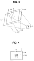
- Fig. 3 is a diagram for illustrating the R correction information and the L correction information.
- Correction information for electrically cutting out a right eye image Ir to be displayed, from an image acquired by a right eye, and a left eye image I1 to be displayed, from an image acquired by a left eye in order to cause the cross point formed by the center of the observation image Vr and the center of the observation image Vl to correspond to a certain particular fixed point C0 after assembly are R correction information and L correction information, respectively.
- Fig. 4 is a diagram showing a first display example of the 2D monitor 3 at the time of a manufacturing inspection
- Fig. 5 is a diagram showing a second display example of the 2D monitor 3 at the time of a manufacturing inspection
- Fig. 6 is a diagram showing a third display example of the 2D monitor 3 at the time of a manufacturing inspection.
- a left eye image picked up by the L image pickup section 121 and R correction identification information stored in the R memory 14r are image-combined by the identification information combining section 2 and displayed on a screen 3a of the 2D monitor 3.
- identification information 32A of the first display example shown in Fig. 4 is a character "R" indicating that correction is performed by R correction information, which is semi-transparently displayed relatively large on a central part of the screen 3a
- identification information 32B of the second display example shown in Fig. 5 is similarly the character "R", which is non-transparently displayed, for example, at an upper-right corner part of the screen 3a in order not to easily obstruct observation of the image 31.
- the 2D monitor 3 is a monitor of such a type that images of a plurality of systems can be simultaneously inputted and can be dividedly displayed on the screen 3a, it is preferred to output an output from the L output section 151 to the 2D monitor 3 via the identification information combining section 2 and, furthermore, simultaneously output an output from the R output section 15r to the 2D monitor 3 via the identification information combining section 2 to perform display, for example, as shown in Fig. 6 .
- an output from the R output section 15r is displayed on a right-side half of the screen 3a, and an output from the L output section 151 is displayed on a left-side half of the screen 3a.
- identification information 32B here, characters "R” indicating that the image has been outputted from the R output section 15r
- identification information 32B here, characters "L” indicating that the image has been outputted from the L output section 151 are non-transparently displayed on an upper-right corner part on the right-side half of the screen 3a and an upper-left corner part of the left-side half of the screen 3 a, respectively.
- the example is an example in which connections of the R and L image pickup sections 12r and 121, the R and L memories 14r and 141, and the R and L output sections 15r and 151 in the stereoscopic endoscope 1 are correctly connected.
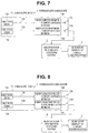
- Fig. 7 is a block diagram showing a configuration of the stereoscopic endoscope 1 at the time of a manufacturing inspection in which the right and left connections are correctly made
- Fig. 8 is a block diagram showing a configuration of the stereoscopic endoscope 1 at the time of a manufacturing inspection in which the right and left memories are incorrectly associated with the image pickup sections and the output sections
- Fig. 9 is a block diagram showing a configuration of the stereoscopic endoscope 1 at the time of a manufacturing inspection in which the right and left output sections are incorrectly associated with the image pickup sections and the memories
- Fig. 7 is a block diagram showing a configuration of the stereoscopic endoscope 1 at the time of a manufacturing inspection in which the right and left connections are correctly made
- Fig. 8 is a block diagram showing a configuration of the stereoscopic endoscope 1 at the time of a manufacturing inspection in which the right and left memories are incorrectly associated with the image pickup sections and the output sections
- Fig. 9 is a block diagram
- FIG. 10 is a block diagram showing a configuration of the stereoscopic endoscope 1 at the time of a manufacturing inspection in which the right and left memories and output sections are incorrectly associated with the image pickup sections;
- Fig. 11 is a diagram showing correct/incorrect classification of association among the right and left output sections, images and pieces of correction information; and
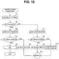
- Fig. 12 is a flowchart showing a flow of the manufacturing inspection.
- the identification information combining section 2 and the 2D monitor 3 are connected to the L output section 151, and confirmation of a left eye image, which should be displayed on the screen 3a, is performed, for example, by inserting a finger immediately before a lens of the L image pickup section 121 (step S1).
- the image displayed on the screen 3a is a left eye image if the finger is displayed (if the displayed image is covered by the finger and cannot be seen), and is a right eye image if the finger is not displayed (if the displayed image can be seen as it is).
- step S2 it is judged whether the displayed image is a left eye image or not.
- correction information is confirmed by seeing identification information (for example, the character "R” or the character "L”) displayed on the screen 3a (step S3).
- a current state is that a left eye image and L correction identification information are displayed on the screen 3a. Therefore, it is known that the current state is the state shown in Fig. 7 in which the L image pickup section 121 and the L memory 141 are associated with each other and connected to the L output section 151, the state shown in a case 1 in Fig. 11 . That is, it is identified that the current state is a state in which correct connections are made (step S5).
- the current state is that a left eye image and R correction identification information are displayed on the screen 3a. Therefore, it is known that the current state is the state shown in Fig. 8 in which the L image pickup section 121 and the R memory 14r are associated with each other and connected to the L output section 151, the state shown in a case 2 in Fig. 11 . That is, it is identified that the current state is a reversed correction state in which, though right and left images outputted from the L output section 151 are correct, pieces of correction information for correcting the images are reversed (step S6).
- step S2 if it is judged at step S2 that the displayed image is not a left eye image but a right eye image, confirmation of the correction information is performed similarly to step S3 (step S7).
- step S8 it is judged whether the correction information is L correction information or not.
- the current state is that a right eye image and R correction identification information are displayed on the screen 3a. Therefore, it is known that the current state is the state shown in Fig. 9 in which the R image pickup section 12r and the R memory 14r are associated with each other and connected to the L output section 151, the state shown in a case 3 in Fig. 11 . That is, it is identified that the current state is a reversed image state in which, though right and left images outputted from the L output section 151 are incorrect, right and left correction information for correcting the images correspond to the right and left images (step S9).
- the current state is that a right eye image and L correction identification information are displayed on the screen 3a. Therefore, it is known that the current state is the state shown in Fig. 10 in which the R image pickup section 12r and the L memory 141 are associated with each other and connected to the L output section 151, the state shown in a case 4 in Fig. 11 . It is identified that the current state is a reversed image and reversed correction state in which not only right/left of an image outputted from the L output section 151 is wrong but also right/left of correction information for correcting the image is also opposite to the right/left of the image (step S10).
- step S11 a process for re-adjustment corresponding to content of the mistake is performed (step S11), and the manufacturing inspection process is performed again after the re-adjustment.
- step S5 if it is confirmed at step S5 that correct connections are made, the manufacturing inspection process ends.
- Fig. 13 is a block diagram showing a configuration of the stereoscopic endoscope system when the stereoscopic endoscope 1 which has been correctly adjusted through the above-described manufacturing inspection is used.
- the stereoscopic endoscope system during use after a manufacturing inspection is provided with the stereoscopic endoscope 1, a 3D video processor 4, a 3D monitor 5, a display position adjusting mechanism 6, and one or more pairs of 3D observation glasses 7.
- the R image pickup section 12r is connected to and associated with the R memory 14r via the R signal line 13r and further connected to the R output section 15r
- the L image pickup section 121 is connected to and associated with the L memory 141 via the L signal line 131 and further connected to the L output section 151. Therefore, the R output section 15r outputs a right eye image and R correction information (or further R correction identification information as necessary), and the L output section 151 outputs a left eye image and L correction information (or further L correction identification information as necessary).
- the 3D video processor 4 is a video processor which is provided with an R image correcting section 41r to which the R output section 15r is connected, an L image correcting section 411 to which the L output section 151 is connected, and a 3D image generating section 42, and which generates a 3D right eye image obtained by correcting a right eye image with R correction information and a 3D left eye image obtained by correcting a left eye image with L correction information.
- the R image correcting section 41r performs correction of performing cutout of an inputted right eye image based on inputted R correction information
- the L image correcting section 411 performs correction of performing cutout of an inputted left eye image based on inputted L correction information.
- the 3D image generating section 42 generates a 3D right eye image, which is a right eye image for stereoscopic observation, based on the right eye image corrected by the R image correcting section 41r and generates a 3D left eye image, which is a left eye image for stereoscopic observation, based on the left eye image corrected by the L image correcting section 411.
- the 3D image generating section 42 is provided with an image shift correction section 43 and is adapted to increase or decrease a convergence angle at time of observing a stereoscopic image by performing image shift of the right eye image corrected by the R image correcting section 41r and performing image shift of the left eye image corrected by the L image correcting section 411 so as to perform control for emphasizing or reducing a stereoscopic effect of a 3D image.
- the 3D video processor 4 may be configured so that it includes the function of the identification information combining section 2 described above, and the 2D monitor 3 can be connected.
- a normal mode and an inspection mode are provided so that the 3D monitor 5 is connected to perform stereoscopic observation in the normal mode, and the 2D monitor 3 is connected to perform a manufacturing inspection and the like as described above in the inspection mode.
- the 3D monitor 5 displays a stereoscopic image based on a 3D right eye image and a 3D left eye image from the 3D video processor 4.
- the 3D monitor 5 is provided with an observation position detecting section 51 which detects a position of an observer relative to the 3D monitor 5 and acquires an observation center position based on the detected position of the observer.
- information about the position of the observer detected by the observation position detecting section 51 includes information about a distance and direction to the observer when the 3D monitor 5 is a base position. Therefore, information about the acquired observation center position also includes information about a distance and direction to the observation center position when the 3D monitor 5 is the base position.
- the observation position detecting section 51 causes a detected position of the observer to be the observation center position.
- the observation position detecting section 51 causes, for example, a mean value (a simple average, a weighted average or the like) of detected positions of the plurality of observers to be the observation center position (otherwise, the observation center position may be acquired by a statistical method such as excluding outliers from calculation targets, instead of the average calculation).
- observation position detecting section 51 is provided in the 3D monitor 5 here, the observation position detecting section 51 may be arranged at a position other than the 3D monitor 5 if necessary information can be acquired.
- the image shift correction section 43 described above performs a process for performing image shift of a 3D right eye image and a 3D left eye image so that a convergence angle is appropriate when the 3D monitor 5 is seen from the observation center position. Note that, though the image shift correction section 43 is provided in the 3D video processor 4 in the above description, this is not limiting, and the image shift correction section 43 may be provided at other position. For example, the image shift correction section 43 may be provided in the 3D monitor 5.
- the 3D monitor 5 and the 2D monitor 3, which is also used during a manufacturing inspection may be realized by switching between modes of one monitor.
- the one monitor functions as the 3D monitor 5 it is possible to display the right/left pieces of identification information. If such an operation is performed, it is preferred to display the left identification information and the right identification information in an area at a left end of a screen 5a (see Fig.
- the display position adjusting mechanism 6 changes a position of the screen 5a of the 3D monitor 5 and includes a display position controlling section 61, and a drive mechanism such as a motor to be described later.
- the display position controlling section 61 causes the display position adjusting mechanism 6 to change the position of the screen of the 3D monitor 5 so that the observation center position comes close to a center of a visual field ⁇ (see Figs. 17 and 18 ), which is a range appropriate for stereoscopy of the 3D monitor 5 (that is, so that the observation center position comes as close to the center of the visual field ⁇ as possible even when it is not possible to cause the observation center position to be the center of the visual field ⁇ , though it is preferable that the observation center position is the center).
- the display position controlling section 61 is provided in the display position adjusting mechanism 6 here, a configuration in which the display position controlling section 61 is provided outside the display position adjusting mechanism 6 is also possible.
- One or a plurality of pairs of 3D observation glasses 7 are provided in the stereoscopic endoscope system.
- the pair of 3D observation glasses 7 is such that enables stereoscopic observation according to a display system of the 3D monitor 5 when worn by an observer.
- the pair of 3D observation glasses 7 becomes a pair of polarizing glasses when the 3D monitor 5 is a polarization type monitor and becomes a pair of liquid crystal shutter glasses when the 3D monitor 5 is an active shutter type monitor.
- the pair of 3D observation glasses 7 adopts a configuration of being provided with a signal transmitting section 71 which transmits a signal receivable by the observation position detecting section 51.
- the observation position detecting section 51 described above is adapted to detect a position of an observer based on a signal received from the signal transmitting section 71.
- a signal transmitted by the signal transmitting section 71 of the present embodiment includes a signal capable of identifying an individuality of the pair of 3D observation glasses 7.
- the observation position detecting section 51 weights the positions of the observers according to detected positions of the observers based on which pair of 3D observation glasses 7 a signal is received from, and then causes a mean value of calculated positions of the plurality of observers to be the observation center position.
- the pair of 3D observation glasses 7 is provided with the signal transmitting section 71.
- the observation position detecting section 51 may be such that detects a position of an observer by performing analysis of an image obtained by picking up an image of an observer side from a 3D monitor 5 side (for example, by performing face detection and performing distance detection based on contrast AF for a detected face, direction detection based on a position of the face in the image and an image pickup angle of view, and the like).
- the convergence angle at time when the distance between the 3D monitor 5 and the observer as shown in Fig. 14 is 1 is indicated by ⁇
- the convergence angle at time when the distance between the 3D monitor 5 and the observer becomes 1' becomes ⁇ ' as shown in Fig. 15 . That is, as the distance between the 3D monitor 5 and the observer changes in the stereoscopic endoscope system, the convergence angle changes. Change in the convergence angle is felt, for example, as change in a feeling of depth in stereoscopy by the observer.
- image shift is performed by the image shift correction section 43 so that an observer within some distance range can appropriately feel the feeling of depth in stereoscopy.
- Such an area appropriate for performing stereoscopic observation is assumed as the visual field ⁇ .
- a crosstalk (such as observing not only a 3D left eye image but also a part of a 3D right eye image by a left eye and observing not only the 3D right eye image but also a part of the 3D left eye image by a right eye, and the like) may occur, and it may be difficult to perform stereoscopy.
- a crosstalk such as observing not only a 3D left eye image but also a part of a 3D right eye image by a left eye and observing not only the 3D right eye image but also a part of the 3D left eye image by a right eye, and the like
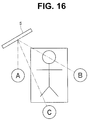
- Fig. 16 is a plan view showing a state that there are three observers in an endoscopy using the stereoscopic endoscope
- Fig. 17 is a side view showing a positional relationship between the visual field ⁇ of the 3D monitor and two of the observers shown in Fig. 16
- Fig. 18 is a plan view showing a positional relationship between the visual field ⁇ of the 3D monitor and the three observers.
- Fig. 16 it is assumed that there are observers A to C who observe the 3D monitor 5, around a subject. When this is laterally seen, the state is, for example, as shown in Fig. 17 , and eyes of the standing observer B are positioned beyond a border of the visual field ⁇ . On the other hand, the observer A, who is sitting, appears to be within the visual field ⁇ in Fig. 17 . When seen from above, however, he is positioned beyond the visual field ⁇ as shown in Fig. 18 .
- the stereoscopic endoscope system of the present embodiment is adapted to, in such a case, automatically perform two kinds of adjustments: adjustment of the convergence angle by performing image shift and position adjustment related to height, direction and the like of the screen 5a of the 3D monitor 5.
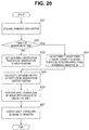
- Fig. 20 is a flowchart showing a flow of a convergence angle adjustment process.
- the observation position detecting section 51 receives a signal transmitted by the signal transmitting section 71 of the pair of 3D observation glasses 7 to acquire a position of an observer (step S21).
- the observation position detecting section 51 judges whether it has acquired a plurality of positions of observers or not (step S22).
- the observation position detecting section 51 sets the detected position of the observer as the observation center position (step S23).
- the observation position detecting section 51 calculates, for example, a weighted average position of the detected plurality of positions of the observers and sets the weighted average position as the observation center position (step S24).
- weight used to calculate a weighted average is set in advance for each individual pair of 3D observation glasses 7 or manually set each time each individual pair of 3D observation glasses 7 is used. Weighting of each observer is performed based on a signal capable of identifying an individual from the pair of 3D observation glasses 7.
- the image shift correction section 43 calculates an amount of shift mainly based on information about a distance from the 3D monitor 5 to the observation center position (or based not only on the distance information but also information about a direction of the observation center position seen from the 3D monitor 5) so that an optimum convergence angle can be obtained at the observation center position set by the process of step S23 or S24 (step S25).
- the image shift correction section 43 performs image shift of a 3D right eye image and a 3D left eye image based on the calculated amount of shift (step S26).
- the 3D video processor 4 outputs the shift-corrected 3D images to the 3D monitor 5, and the 3D monitor 5 performs stereoscopic display of the images (step S27), and the process ends.
- Fig. 19 is a perspective view showing a configuration example of the display position adjusting mechanism 6.
- the display position adjusting mechanism 6 is provided with, for example, a base portion 6a to be placed on a table or the like; a first hinge 62 which is horizontally provided on an edge portion of one end of the base portion 6a and which is rotatable by a first motor or the like; a support portion 6b configured to be rotatable relative to the base portion 6a via the first hinge 62; a second hinge 63 which is horizontally provided on an upper end portion of the support portion 6b and which is rotatable by a second motor or the like; and a third hinge 64 which is provided on a central part of the second hinge 63 and which is rotatable in a direction orthogonal to the second hinge 63 by a third motor or the like.
- the first hinge 62 rotates by control of the display position controlling section 61 (see Fig. 13 ) and moves the 3D monitor 5 (therefore, the screen 5a) in a vertical direction (upward and downward along a gravity direction).
- the second hinge 63 rotates by control of the display position controlling section 61 and adjusts an elevation angle/depression angle (that is, so-called pitch) of the 3D monitor 5 (therefore, the screen 5a).
- the third hinge 64 rotates by control of the display position controlling section 61 and adjusts right and left angles (that is, so-called yaw) of the 3D monitor 5 (therefore, the screen 5a).
- the 3D monitor 5 is attached via the third hinge 64.
- the 3D monitor 5 may be, of course, configured such that the roll is adjustable if it is necessary for some reason.
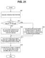
- Fig. 21 is a flowchart showing a flow of a process for position adjustment of the screen 5a of the 3D monitor 5.
- the observation center position is set by performing the process of steps S21 to S24 as described with reference to Fig. 20 .
- the display position controlling section 61 calculates, for example, the center position and normal direction of the screen 5a so that the observation center position set by the process of step S23 or S24 is close to the center of the visual field ⁇ , which is a range appropriate for stereoscopy of the 3D monitor 5 (see Figs. 17 and 18 ), that is, so that the observation center position corresponds to the center of the visual field ⁇ if the observation center position is inside a movable range, and comes to a position which is the closest to the center of the visual field ⁇ if the observation center position is outside the movable range (step S31).
- the display position controlling section 61 drives the first to third motors and the like to rotate the first to third hinges 62 to 64 to perform position adjustment of the 3D monitor 5 so that the center position and normal direction of the screen 5a correspond to the center position and normal direction obtained by calculation of step S31 (step S32), and the process ends.
- a message or the like may be displayed indicating that the direction and height of the 3D monitor 5 are to be manually adjusted.
- a mechanism, a program or the like may be provided which is for weighting a certain particular observer so that a position of each monitor is adjusted or adjusting positions of the monitors so that a particular observer can perform observation with a central value of a visual field as far as possible.
- it is preferred to adopt the polarization type because it is difficult to synchronize right and left signals among the 3D monitors of the active shutter type.
- the pair of 3D observation glasses 7 is, for example, a pair of polarizing glasses, an amount of passing light decreases because light passing through polarizing filters fitted to right and left lens portions is limited to polarized light in a particular direction. If the pair of 3D observation glasses 7 is a pair of liquid crystal shutter glasses, the amount of passing light decreases because a transit time period during which light passes through the right and left lens portions is restricted. Therefore, when observation is performed with use of the pair of 3D observation glasses 7, a field of view becomes dark. If it is the 3D monitor 5 that is to be observed, luminance of the screen 5a can be increased to cope with the darkness. In a case of observing a portion other than the screen 5a which is illuminated with ambient light, the field of view inevitably becomes dark.
- the stereoscopic endoscope 1 and a treatment instrument 8, such as a forceps are inserted in the abdominal cavity via a trocar 81 and another trocar 81, respectively.
- An operation portion 1b of the stereoscopic endoscope 1 on a hand side is outside the trocar 81, and an insertion portion 1a on a distal end side is inserted in the abdominal cavity through the trocar 81.
- the treatment instrument 8 is configured such that a treatment portion 8a is provided on a distal end side of an insertion portion 8b.
- the insertion portion 8b passes through the trocar 81, and the treatment portion 8a on the distal end side is inserted in the abdominal cavity.
- FIG. 22 shows that suturing is being performed in the abdominal cavity with use of a needle 82 (with a thread 83) held by the treatment portion 8a of the treatment instrument 8 while stereoscopic observation is being performed by the stereoscopic endoscope 1.
- the external illumination is also in the unsterile state similarly to the pair of 3D observation glasses 7. Therefore, it is required to ask another person to do the work of applying external illumination when necessary and turning off the external illumination when it becomes unnecessary, which causes work to be very complicated and leads to delay of a surgical procedure.
- the sutured portion is out of the field of view when another treatment instrument is in the abdominal cavity and suturing is being performed.
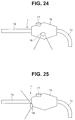
- Fig. 24 is a diagram showing a configuration in which a hand illuminating section 16 is provided on a side face of the operation portion 1b of the stereoscopic endoscope 1
- Fig. 25 is a diagram showing a configuration in which the hand illuminating section 16 is provided on a connection face between the operation portion 1b and the insertion portion 1a of the stereoscopic endoscope 1
- Fig. 24 is a diagram showing a configuration in which the hand illuminating section 16 is provided on a connection face between the operation portion 1b and the insertion portion 1a of the stereoscopic endoscope 1
- Fig. 25 is a diagram showing a configuration in which the hand illuminating section 16 is provided on a connection face between the operation portion 1b and the insertion portion 1a of the stereoscopic endoscope 1
- Fig. 24 is a diagram showing a configuration in which a hand illuminating section 16 is provided on a side face of the operation portion 1b of the stereoscopic endo
- Fig. 26 is a diagram showing a configuration example in which a light source of the hand illuminating section 16 is also used as a light source of illuminating light to a distal end portion of the insertion portion 1a of the stereoscopic endoscope 1;
- Fig. 27 is a diagram showing a configuration example in which a light emission source is provided on the hand illuminating section 16 to perform control via a 3D video processor 4A;
- Fig. 28 is a diagram showing a configuration example in which the light emission source is provided on the hand illuminating section 16 to perform control within the operation portion 1b of the stereoscopic endoscope 1;
- Fig. 29 is a diagram showing a configuration example in which a hand illuminating section 86 is provided on a hand side of the treatment instrument 8.
- Fig. 24 shows a configuration example in which the hand illuminating section 16 is provided on the side face of the operation portion 1b in the stereoscopic endoscope 1, and, further, a hand illuminating switch 17 for switching on/off of the hand illuminating section 16 is provided on the operation portion 1b.
- Fig. 25 shows a configuration example in which, though arrangement of the hand illuminating switch 17 is similar to that of Fig. 24 , the hand illuminating section 16 is provided on a face on a distal end side of the operation portion 1b of the stereoscopic endoscope 1 (the face of connection with the insertion portion 1a).
- a cable 1c such as a universal cable and an illumination cable, is provided being extended from the hand side of the stereoscopic endoscope 1, and is connected to a light source device 9 or a video processor or the like which includes a light source device via a connector 1d.
- the hand illuminating section 16 shown in Fig. 26 is in a configuration example in which a part of a light guide 18 which is configured, for example, with an optical fiber bundle and which transmits illuminating light from the light source device 9 to a distal end side of the insertion portion 1a is branched to be a branched light guide 18a, and light is emitted via an illuminating window to be used as illuminating light for hands. Therefore, the hand illuminating section 16 is provided, for example, with an illumination cover openable and closable relative to the illuminating window, and on/off of illumination is switched by operating the illumination cover.
- an operation input from the hand illuminating switch 17 is inputted to the 3D video processor 4A via a signal line 17a arranged in the cable 1c.
- the 3D video processor 4A supplies power to the hand illuminating section 16 via a power line 16a arranged in the cable 1c.
- the hand illuminating section 16 is configured, including a lamp such as an LED as a light emitting source, and emits light when power is supplied.
- the 3D video processor 4A shuts down power supply to the hand illuminating section 16, and light emission stops.
- Fig. 28 shows a configuration example in which light emission control of the hand illuminating section 16 according to an operation of the hand illuminating switch 17 is performed in the operation portion 1b. That is, a control board 17b and a power source 16b are further provided in the operation portion 1b, and the signal line 17a from the hand illuminating switch 17 and the power line 16a from the power source 16b are connected to the control board 17b and the hand illuminating section 16, respectively. Note that it is similar to the configuration example of Fig. 27 that the hand illuminating section 16 is configured including a lamp such as an LED.
- an illumination on/off signal from the hand illuminating switch 17 is inputted to the control board 17b so that the control board 17b controls the power source 16b to control on/off of power supply to the hand illuminating section 16, that is, emission/stop of illuminating light for hands.
- the some examples described above are configuration examples in which the hand illuminating section 16 is provided on a part other than the insertion portion 1a of the stereoscopic endoscope 1.
- the configurations of the hand illuminating section 16 and the hand illuminating switch 17 as shown in Figs. 24 to 28 are not limited to being applied only to the stereoscopic endoscope 1 but can be widely applied to other endoscopes including a 2D endoscope.
- Fig. 29 is a diagram showing a configuration example in which the hand illuminating section 86 is provided on the hand side of the treatment instrument 8.
- the treatment instrument 8 is provided with the treatment portion 8a on a distal end side, the insertion portion 8b extended from the treatment portion 8a to the hand side, and an operation portion 8c connectedly arranged on a hand side of the insertion portion 8b.
- the operation portion 8c is provided with the hand illuminating section 86 and a hand illuminating switch 87.
- a surgeon and assistants it is preferred for a surgeon and assistants to perform work such as a surgical operation while observing a 3D image having a deep stereoscopic effect.
- a circulating nurse or the like who frequently moves in an operating room, however, he not only observes the 3D monitor 5 but also performs various works such as preparing treatment instruments, gauze and the like while seeing his hands, and, therefore, there is a possibility that eye fatigue or visually induced motion sickness is caused by observing the 3D monitor 5 outside the visual field ⁇ in stereoscopic observation or by frequently switching between observation of the 3D monitor 5 and observation of the actual field of view nearby.
- each observer can choose between 2D observation and 3D observation as desired. Therefore, a configuration example in which such desired choice is enabled in a case where the 3D monitor 5 is of a polarization type and the pair of 3D observation glasses 7 is a pair of polarizing glasses will be described with reference to Figs. 30 and 31 .
- Fig. 30 is a diagram showing a configuration in which a knob cap is attached to a pair of 3D observation glasses which is capable of choosing between 2D observation and 3D observation; and Fig. 31 is a diagram showing that the knob cap of the pair of 3D observation glasses is operated to switch between the 2D observation and the 3D observation.
- polarization directions of a right eye polarizing filter 7R and a left eye polarizing filter 7L fitted to lens portions are different by 90° during stereoscopic observation.
- At least one of the right eye polarizing filter 7R and the left eye polarizing filter 7L is provided with a rotation mechanism capable of rotating a filter polarization direction around an observing line of sight by at least 90°, and a knob 72 for manually performing a rotation operation of the rotation mechanism.
- a sterilized knob cap 73 is detachably fitted to the knob 72. Thereby, even if an observer performs an operation of switching between 2D observation and 3D observation via the knob cap 73, a sterilized state of the observer is not damaged.
- the rotation mechanism when the rotation mechanism is attached to both on the left eye polarizing filter 7L side and on the right eye polarizing filter 7R side, it is possible to observe any of a right eye image and a left eye image with both eyes as desired.
- both of the rotation mechanisms when both of the rotation mechanisms are simultaneously operated, the right eye image is observed with a left eye, and the left eye image is observed with a right eye (reversed images are caused). Therefore, it is preferred to further provide a mechanism for, when a rotation operation of one of the polarizing filter is performed, inhibiting a rotation operation of the other polarizing filter (a mechanism for inhibiting simultaneous operations).
- rotation of the right eye polarizing filter 7R or the left eye polarizing filter 7L is not limited to being manually performed via the knob 72.
- the rotation may be electrically performed with use of a drive system such as a motor.
- a configuration is made in which an operation switch is provided on the pair of 3D observation glasses 7, and an operation of the drive system is performed according to an input operation from the operation switch.
- the 3D monitor 5 is of the active shutter type or of a liquid crystal shutter type, it is possible for each observer to switch between 2D observation and 3D observation by himself by adopting the configuration of switching between 2D observation and 3D observation by a switch operation as described above.
- the switching operation becomes smooth, and the switching operation can be performed by one press of the switch and the like. Therefore, the switching operation becomes easier than the case of rotating the knob 72 by 90 degrees, and it becomes possible to further shorten a time period during which a surgical operation is discontinued.
- pieces of correction information and pieces of identification information indicating right and left of the pieces of correction information are stored in right and left memories, respectively, and the pieces of identification information are image-combined with images outputted from right and left output sections, respectively. Therefore, by inserting, for example, a finger on a front of a right or left image pickup section, whether a right image or a left image can be confirmed. Moreover, by seeing the identification information combined with the image, it becomes possible to confirm whether correction information is for right or left.
- a position of an observer relative to the 3D monitor 5 is detected; an observation center position is further acquired; and image shift of a 3D right eye image and a 3D left eye image is performed based on the observation center position. Therefore, it becomes possible to automatically and appropriately adjust a convergence angle when the 3D monitor 5 is seen from the observation center position. Therefore, it becomes possible for more observers to perform stereoscopic observation with an appropriate feeling of depth.
- a position of a screen of the 3D monitor 5 is changed based on the observation center position, it is possible to automatically perform adjustment for causing the observation center position to be close to a center of a visual field ⁇ and makes it possible for more observers to perform appropriate stereoscopic observation.
- the signal transmitting section 71 of the pair of 3D observation glasses 7 in the case of causing the signal transmitting section 71 of the pair of 3D observation glasses 7 to transmit a signal capable of identifying an individual, it is possible to obtain an observation center position by heavily weighting a particular observer. Thereby, it becomes possible to enable a main observer (for example, a chief surgeon) to be able to always perform observation at an optimum position.
- a main observer for example, a chief surgeon
- the stereoscopic endoscope system of the present embodiment it becomes possible to easily confirm whether there is a right/left mistake in manufacture of the stereoscopic endoscope 1.
- a stereoscopic endoscope system has been mainly described above, an operation method for causing the stereoscopic endoscope system to operate as described above is also possible.
- a processing program for causing a computer to operate the stereoscopic endoscope system as described above, a non-temporary computer-readable recording medium in which the processing program is recorded, and the like are also possible.
- the present invention is not limited to the above embodiments as they are, and the components can be modified and embodied within a range not departing from the spirit of the invention at a stage of practicing the invention.
- various aspects of the invention can be formed by appropriately combining a plurality of components disclosed in the above embodiments. For example, some components may be deleted from all the components shown in the embodiments. Furthermore, components from different embodiments may be appropriately combined. Thus, it is, of course, possible to make various modifications and applications within the range not departing from the spirit of the invention.
Landscapes
- Health & Medical Sciences (AREA)
- Life Sciences & Earth Sciences (AREA)
- Engineering & Computer Science (AREA)
- Surgery (AREA)
- Physics & Mathematics (AREA)
- Signal Processing (AREA)
- Multimedia (AREA)
- General Health & Medical Sciences (AREA)
- Optics & Photonics (AREA)
- Radiology & Medical Imaging (AREA)
- Heart & Thoracic Surgery (AREA)
- Public Health (AREA)
- Pathology (AREA)
- Medical Informatics (AREA)
- Molecular Biology (AREA)
- Animal Behavior & Ethology (AREA)
- Nuclear Medicine, Radiotherapy & Molecular Imaging (AREA)
- Biomedical Technology (AREA)
- Veterinary Medicine (AREA)
- Biophysics (AREA)
- Astronomy & Astrophysics (AREA)
- General Physics & Mathematics (AREA)
- Endoscopes (AREA)
- Instruments For Viewing The Inside Of Hollow Bodies (AREA)
Abstract
Description
- The present invention relates to a stereoscopic endoscope system which includes a stereoscopic endoscope having a right image pickup section and a left image pickup section.
- A general endoscope apparatus is a so-called 2D endoscope apparatus for observing a subject site as a planar image. However, since the planar image does not give a perspective feeling, a stereoscopic effect cannot be obtained when subtle unevenness or the like on a surface of a body cavity wall is observed as a specific example of the subject site.
- Therefore, a stereoscopic endoscope apparatus making it possible to three-dimensionally observe an object has been proposed. A conventional stereoscopic endoscope apparatus is adapted to, for example, form object images with two objective optical systems having a parallax which are provided at a distal end portion, transmit the object images to an eyepiece portion at a rear end portion via a pair of relay optical systems and a pair of eyepiece optical systems, and perform megascopic observation or image pickup by a pair of TV cameras.
- As an example of such a conventional stereoscopic endoscope apparatus, for example, a second embodiment of
Japanese Patent Application Laid-Open Publication No. 2004-222937 - Further, Japanese Patent Application Laid-Open Publication No.
10-126814 - Further, Japanese Patent Application Laid-Open Publication No.
2005-223495 - The technique described in each of the official gazettes described above is a technique utilized at time of using a manufactured stereoscopic endoscope. A problem which occurs at time of manufacturing the stereoscopic endoscope will be described with reference to
Figs. 32 to 35 . - First,
Fig. 32 is a block diagram showing a configuration in which a stereoscopic endoscope in which right and left image pickup sections and right and left memories are reversely connected is observed on a 3D monitor. - A
stereoscopic endoscope 101 is provided with: an Rimage pickup section 112r and anR output section 115r which are arranged on a right side of anendoscope body 111; an L image pickup section 1121 and an L output section 1151 which are arranged on a left side of theendoscope body 111; anR signal line 113r extended from the Rimage pickup section 112r; anL signal line 1131 extended from the L image pickup section 1121; anR memory 114r which stores R correction information for correcting a right eye image, and an L memory 1141 which stores L correction information for correcting a left eye image. - The R
image pickup section 112r and the L image pickup section 1121 are accurately positioned and assembled so that a right eye image and a left eye image for constituting a stereoscopic image can be acquired, respectively. However, positioning at a pixel pitch level is difficult. Therefore, correction information for cutting out a right eye image acquired from the Rimage pickup section 112r and a left eye image acquired from the L image pickup section 1121 and performing positioning so that a stereoscopic image can be accurately configured is recorded in each of theR memory 114r and the L memory 1141. - A
3D monitor 105 is adapted so that an image outputted from theR output section 115r of the stereoscopic endoscope and an image outputted from the L output section 1151 of the stereoscopic endoscope are inputted as a right eye image and a left eye image, respectively, to display a stereoscopic image. - It is assumed that, in such a configuration, the
R signal line 113r extended from the Rimage pickup section 112r is connected to the L memory 1141, and theL signal line 1131 extended from the L image pickup section 1121 is connected to the L memory 1141 due to an assembly mistake. - In this case, a right eye image corrected with L correction information is outputted from the L output section 1151 and displayed on the
3D monitor 105 as a left eye image, and a left eye image corrected with R correction information is outputted from theR output section 115r and displayed on the3D monitor 105 as a right eye image. - Therefore, an inspection using a
2D monitor 103, as shown inFig. 33 , is performed at time of assembly.Fig. 33 is a block diagram showing a configuration in which a manufacturing inspection of the stereoscopic endoscope shown inFig. 32 is performed with use of a 2D monitor. - The
2D monitor 103 is used by being connected to one of the output sections of thestereoscopic endoscope 101. In the example shown inFig. 33 , the2D monitor 103 is connected to the L output section 151. - Then, for example, a finger is inserted in an image pickup range of only the L image pickup section 1121 to confirm whether the finger is displayed on the
2D monitor 103. In an incorrect connection state as shown inFig. 33 , since it is a right eye image picked up by the Rimage pickup section 112r that is outputted from the L output section 1151, the finger is not observed on the2D monitor 103, and it can be detected that the L image pickup section 1121 is not connected to the L output section 1151. Therefore, it is possible to confirm the connection state of theR signal line 113r and theL signal line 1131 again and return the connection state to a correct connection state. - Next, an example in which detection is not possible only by such an inspection method will be described with reference to
Figs. 34 and 35. Fig. 34 is a block diagram showing a configuration in which a stereoscopic endoscope in which pieces of correction information to be stored into memories are stored with left and right reversed is observed on a 3D monitor; andFig. 35 is a block diagram showing a configuration in which a manufacturing inspection of the stereoscopic endoscope shown inFig. 34 is performed with use of a 2D monitor. - A right eye image should be corrected with R correction information, and a left eye image should be corrected with L correction information. However, in the example shown in
Figs. 34 and 35 , the R correction information and the L correction information are reversely stored in the memories. Therefore, the Rimage pickup section 112r is connected to the L memory 1141 and theR output section 115r, and the L image pickup section 1121 is connected to theR memory 114r and the L output section 1151. - At this time, when the
2D monitor 103 is connected to the L output section 1151, and a finger is inserted in the image pickup range of only the L image pickup section 1121, the finger is displayed on the2D monitor 103, and the connection state of the image pickup sections appears to be correct at a glance. It is difficult to confirm whether a displayed left eye image has been correctly corrected with L correction information or incorrectly corrected with R correction information, by observing only the2D monitor 103. - Therefore, it is also conceivable to actually observe and confirm a stereoscopic image further using a 3D monitor, as shown in
Fig. 34 . It is known, however, that an ability to recognize a stereoscopic image varies among individuals. Some literatures describe that about 10% of people cannot recognize a stereoscopic image as 3D. Therefore, even if a stereoscopic image is displayed with use of a 3D monitor to perform an inspection for confirming whether correction information is correct or incorrect by visual inspection, a correct inspection result cannot be necessarily obtained. - Thus, there is a demand for establishment of an inspection method in which a correct inspection can be performed even in such a case.
- The present invention has been made in view of the above situation, and its object is to provide a stereoscopic endoscope system making it possible to easily confirm whether there is a right/left mistake in manufacture of a stereoscopic endoscope.
- A stereoscopic endoscope system according to a certain aspect of the present invention is a stereoscopic endoscope system comprising a stereoscopic endoscope, the stereoscopic endoscope system comprising: the stereoscopic endoscope comprising: an endoscope body; a right image pickup section provided on a right side of the endoscope body and acquiring a right eye image; a left image pickup section provided on a left side of the endoscope body and acquiring a left eye image; a right memory associated with one of the right image pickup section and the left image pickup section and storing correction information for right for correcting the right eye image so that the right eye image is for stereoscopy, and right identification information for identifying that what is stored is the correction information for right; a left memory associated with another of the right image pickup section and the left image pickup section and storing correction information for left for correcting the left eye image so that the left eye image is for stereoscopy, and left identification information for identifying that what is stored is the correction information for left; a right output section provided on the right side of the endoscope body and outputting one of a first identification information/image set constituted by the right-eye image and one of the right identification information and the left identification information associated with the right image pickup section and a second identification information/image set constituted by the left eye image and another of the right identification information and the left identification information associated with the left image pickup section at time of a manufacturing inspection; and a left output section provided on the left side of the endoscope body, and outputting another of the first identification information/image set and the second identification information/image set at the time of the manufacturing inspection; and an identification information combining section capable of performing image combination of an image and identification information of an identification information/image set inputted from the right output section to output a combined image as a right output image and performing image combination of an image and identification information of an identification information/image set inputted from the left output section to output a combined image as a left output image.
-
-
Fig. 1 is a block diagram showing a configuration of a stereoscopic endoscope system in which right and left connections are incorrectly made at time of manufacture in a first embodiment of the present invention; -
Fig. 2 is a diagram showing a more specific configuration of the stereoscopic endoscope in which the right and left connections are incorrectly made in the above first embodiment; -
Fig. 3 is a diagram for illustrating R correction information and L correction information in the above first embodiment; -
Fig. 4 is a diagram showing a first display example of a 2D monitor at time of a manufacturing inspection in the above first embodiment; -
Fig. 5 is a diagram showing a second display example of the 2D monitor at the time of a manufacturing inspection in the above first embodiment; -
Fig. 6 is a diagram showing a third display example of the 2D monitor at the time of a manufacturing inspection in the above first embodiment; -
Fig. 7 is a block diagram showing a configuration of the stereoscopic endoscope at the time of a manufacturing inspection in which the right and left connections are correctly made in the above first embodiment; -
Fig. 8 is a block diagram showing a configuration of the stereoscopic endoscope at the time of a manufacturing inspection in which right and left memories are incorrectly associated with image pickup sections and output sections in the above first embodiment; -
Fig. 9 is a block diagram showing a configuration of the stereoscopic endoscope at the time of a manufacturing inspection in which the right and left output sections are incorrectly associated with the image pickup sections and the memories in the above first embodiment; -
Fig. 10 is a block diagram showing a configuration of the stereoscopic endoscope at the time of a manufacturing inspection in which the right and left memories and output sections are incorrectly associated with the image pickup sections in the above first embodiment; -
Fig. 11 is a diagram showing correct/incorrect classifications of association among the right and left output sections, images and pieces of correction information in the above first embodiment; -
Fig. 12 is a flowchart showing a flow of the manufacturing inspection in the above first embodiment; -
Fig. 13 is a block diagram showing a configuration of the stereoscopic endoscope system when the stereoscopic endoscope which has been correctly adjusted through a manufacturing inspection is used in the above first embodiment; -
Fig. 14 is a diagram showing a convergence angle when there is a certain distance between a 3D monitor and an observer in the above first embodiment; -
Fig. 15 is a diagram showing a convergence angle when there is another distance between the 3D monitor and the observer in the above first embodiment; -
Fig. 16 is a plan view showing a state that there are three observers in an endoscopy using the stereoscopic endoscope of the above first embodiment; -
Fig. 17 is a side view showing a positional relationship between a visual field of the 3D monitor and two of the observers shown inFig. 16 in the above first embodiment; -
Fig. 18 is a plan view showing a positional relationship between the visual field of the 3D monitor and the three observers in the above first embodiment; -
Fig. 19 is a perspective view showing a configuration example of a display position adjusting mechanism in the above first embodiment; -
Fig. 20 is a flowchart showing a flow of a convergence angle adjustment process in the above first embodiment; -
Fig. 21 is a flowchart showing a flow of a process for position adjustment of a screen of the 3D monitor in the above first embodiment; -
Fig. 22 is a diagram showing that suturing is being performed in an abdominal cavity while observation is being performed with the stereoscopic endoscope in the above first embodiment; -
Fig. 23 is a diagram showing that a needle is taken out from the inside of the abdominal cavity, and a thread attached to the needle is cut at hand in the above first embodiment; -
Fig. 24 is a diagram showing a configuration in which a hand illuminating portion is provided on a side face of an operation portion of the stereoscopic endoscope in the above first embodiment; -
Fig. 25 is a diagram showing a configuration in which the hand illuminating section is provided on a connection face between the operation portion and an insertion portion of the stereoscopic endoscope in the above first embodiment; -
Fig. 26 is a diagram showing a configuration example in which a light source of the hand illuminating section is also used as a light source of illuminating light to a distal end portion of the insertion portion of the stereoscopic endoscope in the above first embodiment; -
Fig. 27 is a diagram showing a configuration example in which a light emission source is provided on the hand illuminating section to perform control via a 3D video processor in the above first embodiment; -
Fig. 28 is a diagram showing a configuration example in which the light emission source is provided on the hand illuminating section to perform control within the operation portion of the stereoscopic endoscope in the above first embodiment; -
Fig. 29 is a diagram showing a configuration example in which a hand illuminating section is provided on a hand side of a treatment instrument in the above first embodiment; -
Fig. 30 is a diagram showing a configuration in which a knob cap is attached to a pair of 3D observation glasses which is capable of choosing between 2D observation and 3D observation in the above first embodiment; -
Fig. 31 is a diagram showing that the knob cap of the pair of 3D observation glasses is operated to switch between the 2D observation and the 3D observation in the above first embodiment; -
Fig. 32 is a block diagram showing a conventional configuration in which a stereoscopic endoscope in which right and left image pickup sections and right and left memories are reversely connected is observed on a 3D monitor; -
Fig. 33 is a block diagram showing a conventional configuration in which a manufacturing inspection of the stereoscopic endoscope shown inFig. 32 is performed with use of a 2D monitor; -
Fig. 34 is a block diagram showing a conventional configuration in which a stereoscopic endoscope in which pieces of correction information to be stored into memories are stored with left and right reversed is observed on a 3D monitor; and -
Fig. 35 is a block diagram showing a conventional configuration in which a manufacturing inspection of the stereoscopic endoscope shown inFig. 34 is performed with use of a 2D monitor. - An embodiment of the present invention will be described below with reference to drawings.
-
Figs. 1 to 31 show a first embodiment of the present invention, andFig. 1 is a block diagram showing a configuration of a stereoscopic endoscope system in which right and left connections are incorrectly made at time of manufacture. - The stereoscopic endoscope system of the present embodiment is provided with a
stereoscopic endoscope 1, an identificationinformation combining section 2 and a2D monitor 3. - The
stereoscopic endoscope 1 has anendoscope body 11, an Rimage pickup section 12r, which is a right image pickup section, an L image pickup section 121, which is a left image pickup section, anR signal line 13r, which is a right signal line extended from the Rimage pickup section 12r, an L signal line 131, which is a left signal line extended from the L image pickup section 121, anR memory 14r, which is a right memory, an L memory 141, which is a left memory, anR output section 15r, which is a right output section, and an L output section 151, which is a left output section. Note that right or a right eye is indicated by R, and left or a left eye is indicated by L below. - The R
image pickup section 12r is provided on a right side of a distal end of theendoscope body 11 to acquire a right eye image. - The L image pickup section 121 is provided on a left side of the distal end of the
endoscope body 11 to acquire a left eye image. - Here, when same image pickup sections are used as the right and left image pickup sections, an image pickup section incorporated on a right side of the
endoscope body 11 becomes the Rimage pickup section 12r, and an image pickup section incorporated on a left side of theendoscope body 11 becomes the L image pickup section 121. It can be thought that, when different image pickup sections are used as the right and left image pickup sections, they can be identified from incorporated appearances, and it does not happen that the right and left image pickup sections are reversely incorporated relative to the endoscope body 11 (that is, it does not happen that the L image pickup section 121 is incorporated on the right side of theendoscope body 11, and it does not happen that the Rimage pickup section 12r is incorporated on the left side of the endoscope body 11). - The
R memory 14r is associated with one of the Rimage pickup section 12r and the L image pickup section 121, and stores R correction information, which is correction information for right for correcting a right eye image so that the right eye image is for stereoscopy, and R correction identification information, which is right identification information for identifying that what theR memory 14r stores is the R correction information. Here, the R correction information is correction information for cutting out a right eye image acquired from the Rimage pickup section 12r and performing positioning so that a stereoscopic image can be accurately configured. - The L memory 141 is associated with the other of the R
image pickup section 12r and the L image pickup section 121, and stores L correction information, which is correction information for left for correcting a left eye image so that the left eye image is for stereoscopy, and L correction identification information, which is left identification information for identifying that what the L memory 141 stores is the L correction information. Here, the L correction information is correction information for cutting out a left eye image acquired from the L image pickup section 121 and performing positioning so that a stereoscopic image can be accurately configured. - Note that it can be thought that, since the correction information and the identification information are collectively stored in the memory, it does not happen that R/L inconsistency between the correction information and the identification information occurs (that is, it does not happen that R correction information and L correction identification information are stored in the same memory, and it does not happen that L correction information and R correction identification information are stored in the same memory).
- Further, though an example in which the R
image pickup section 12r or the L image pickup section 121 is directly connected and associated with theR memory 14r or the L memory 141 is shown in the present embodiment, they do not have to be directly connected. More generally, an image pickup section (12r or 121) which has picked up an image outputted from one of theR output section 15r and the L output section 151 and a memory (14r or 141) which stores correction information outputted from the same one output section are in a relationship of being mutually associated, and, similarly, an image pickup section (121 or 12r) which has picked up an image outputted from the other of theR output section 15r and the L output section 151 and a memory (141 or 14r) which stores correction information outputted from the other output section are in a relationship of being mutually associated. - The
R output section 15r is provided on the right side of theendoscope body 11, and outputs one of a first identification information/image set constituted by a right eye image and one of the right identification information and the left identification information which is associated with the Rimage pickup section 12r and a second identification information/image set constituted by a left eye image and the other of the right identification information and the left identification information which is associated with the L image pickup section 121 at the time of a manufacturing inspection. - The L output section 151 is provided on the left side of the
endoscope body 11, and outputs the other of the first identification information/image set and the second identification information/image set at the time of the manufacturing inspection. - Here, it can be thought that, since output sections arranged on the right and left sides of the
endoscope body 11 become theR output section 15r and the L output section 151, respectively, it does not happen that the right and left output sections are reversed (that is, it does not happen that the L output section 151 is arranged on the right side of theendoscope body 11, or theR output section 15r is arranged on the left side of the endoscope body 11). - Further, the identification
information combining section 2 can perform image combination of an image and identification information of an identification information/image set inputted from theR output section 15r to output a combined image as a right output image, and can perform image combination of an image and identification information of an identification information/image set inputted from the L output section 151 to output a combined image as a left output image. - The 2D monitor 3 is a display device which displays a two-dimensional image. The 2D monitor 3 is connected to the identification
information combining section 2 such that at least one of a right output image and a left output image can be inputted, and displays a right output image, a left output image, or right and left output images inputted. - Note that
Fig. 1 shows an example in which the Rimage pickup section 12r is connected to theR output section 15r, being associated with the L memory 141, and the L image pickup section 121 is connected to the L output section 151, being associated with theR memory 14r (that is, an example in which correct assembly is not established). - That is, in the example shown in
Fig. 1 , theR signal line 13r extended from the Rimage pickup section 12r is connected to the L memory 141 and furthermore connected to theR output section 15r. Further, the L signal line 131 extended from the L image pickup section 121 is connected to theR memory 14r and furthermore connected to the L output section 151. - In the example shown in
Fig. 1 , the identificationinformation combining section 2 and the2D monitor 3 are connected to the L output section 151. - According to such a configuration, an image and identification information combined with the image are to be displayed on the
2D monitor 3. - Next,
Fig. 2 is a diagram showing a more specific configuration of thestereoscopic endoscope 1 in which right and left connections are incorrectly made. - The R
image pickup section 12r and the L image pickup section 121 are each provided with an objectiveoptical system 12a, and animage pickup device 12b which performs photoelectric conversion of an optical image formed by the objectiveoptical system 12a to output an image. - The
R signal line 13r and the L signal line 131 are connected, for example, to one face and the other face on a distal end side of asubstrate 19, respectively, and memories are implemented on the one face and the other face of thesubstrate 19. By L correction information and L correction identification information being stored into the memory implemented on one face of thesubstrate 19, the memory becomes the L memory 141. Similarly, by R correction information and R correction identification information being stored in the memory implemented on the other face of thesubstrate 19, the memory becomes theR memory 14r. Moreover, theR output section 15r and the L output section 151 are implemented on one face and the other face on a proximal end side of thesubstrate 19, respectively. - Next,
Fig. 3 is a diagram for illustrating the R correction information and the L correction information. - Even if the R
image pickup section 12r and the L image pickup section 121 are accurately assembled to theendoscope body 11, it is generally difficult to cause a cross point formed by a center Cr of an observation image Vr at time of observing a right eye image Ir picked up by the Rimage pickup section 12r by a right eye as it is and a center Cl of an observation image Vl at time of observing a left eye image Il picked up by the L image pickup section 121 by a left eye as it is to completely correspond to a certain particular position at time of assembly. - Correction information for electrically cutting out a right eye image Ir to be displayed, from an image acquired by a right eye, and a left eye image I1 to be displayed, from an image acquired by a left eye in order to cause the cross point formed by the center of the observation image Vr and the center of the observation image Vl to correspond to a certain particular fixed point C0 after assembly are R correction information and L correction information, respectively.
- Some display examples of the
2D monitor 3 will be described with reference toFigs. 4 to 6 .Fig. 4 is a diagram showing a first display example of the2D monitor 3 at the time of a manufacturing inspection;Fig. 5 is a diagram showing a second display example of the2D monitor 3 at the time of a manufacturing inspection; andFig. 6 is a diagram showing a third display example of the2D monitor 3 at the time of a manufacturing inspection. - In the configuration example shown in
Fig. 1 , a left eye image picked up by the L image pickup section 121 and R correction identification information stored in theR memory 14r are image-combined by the identificationinformation combining section 2 and displayed on ascreen 3a of the2D monitor 3. - A
same image 31 is displayed inFigs. 4 and5 . As for how to display identification information, however,identification information 32A of the first display example shown inFig. 4 is a character "R" indicating that correction is performed by R correction information, which is semi-transparently displayed relatively large on a central part of thescreen 3a, whileidentification information 32B of the second display example shown inFig. 5 is similarly the character "R", which is non-transparently displayed, for example, at an upper-right corner part of thescreen 3a in order not to easily obstruct observation of theimage 31. - Further, if the
2D monitor 3 is a monitor of such a type that images of a plurality of systems can be simultaneously inputted and can be dividedly displayed on thescreen 3a, it is preferred to output an output from the L output section 151 to the2D monitor 3 via the identificationinformation combining section 2 and, furthermore, simultaneously output an output from theR output section 15r to the2D monitor 3 via the identificationinformation combining section 2 to perform display, for example, as shown inFig. 6 . - In the third display example shown in
Fig. 6 , an output from theR output section 15r is displayed on a right-side half of thescreen 3a, and an output from the L output section 151 is displayed on a left-side half of thescreen 3a. At this time, for example, in an aspect similar to that ofFig. 5 ,identification information 32B (here, characters "R") indicating that the image has been outputted from theR output section 15r andidentification information 32B (here, characters "L") indicating that the image has been outputted from the L output section 151 are non-transparently displayed on an upper-right corner part on the right-side half of thescreen 3a and an upper-left corner part of the left-side half of thescreen 3 a, respectively. - Note that, in the example shown in
Fig. 6 , since aright eye image 31r and the character "R", which is the R correction identification information, are displayed on the right-side half of thescreen 3a, and a left eye image 311 and the character "L", which is the L correction identification information, are displayed on the left-side half of thescreen 3 a, the example is an example in which connections of the R and Limage pickup sections 12r and 121, the R andL memories 14r and 141, and the R andL output sections 15r and 151 in thestereoscopic endoscope 1 are correctly connected. - Next, a flow of a manufacturing inspection will be described along
Fig. 12 with reference toFigs. 7 to 11 .Fig. 7 is a block diagram showing a configuration of thestereoscopic endoscope 1 at the time of a manufacturing inspection in which the right and left connections are correctly made;Fig. 8 is a block diagram showing a configuration of thestereoscopic endoscope 1 at the time of a manufacturing inspection in which the right and left memories are incorrectly associated with the image pickup sections and the output sections;Fig. 9 is a block diagram showing a configuration of thestereoscopic endoscope 1 at the time of a manufacturing inspection in which the right and left output sections are incorrectly associated with the image pickup sections and the memories;Fig. 10 is a block diagram showing a configuration of thestereoscopic endoscope 1 at the time of a manufacturing inspection in which the right and left memories and output sections are incorrectly associated with the image pickup sections;Fig. 11 is a diagram showing correct/incorrect classification of association among the right and left output sections, images and pieces of correction information; andFig. 12 is a flowchart showing a flow of the manufacturing inspection. - When a process shown in
Fig. 12 is started, for example, the identificationinformation combining section 2 and the2D monitor 3 are connected to the L output section 151, and confirmation of a left eye image, which should be displayed on thescreen 3a, is performed, for example, by inserting a finger immediately before a lens of the L image pickup section 121 (step S1). In this case, the image displayed on thescreen 3a is a left eye image if the finger is displayed (if the displayed image is covered by the finger and cannot be seen), and is a right eye image if the finger is not displayed (if the displayed image can be seen as it is). - Then, it is judged whether the displayed image is a left eye image or not (step S2).
- Here, if it is judged that the displayed image is a left eye image, correction information is confirmed by seeing identification information (for example, the character "R" or the character "L") displayed on the
screen 3a (step S3). - It is judged whether the confirmed correction information is L correction information or not (step S4).
- Here, if it is judged that the correction information is L correction information, a current state is that a left eye image and L correction identification information are displayed on the
screen 3a. Therefore, it is known that the current state is the state shown inFig. 7 in which the L image pickup section 121 and the L memory 141 are associated with each other and connected to the L output section 151, the state shown in acase 1 inFig. 11 . That is, it is identified that the current state is a state in which correct connections are made (step S5). - Further, if it is judged at step S4 that the correction information is not L correction information but R correction information, the current state is that a left eye image and R correction identification information are displayed on the
screen 3a. Therefore, it is known that the current state is the state shown inFig. 8 in which the L image pickup section 121 and theR memory 14r are associated with each other and connected to the L output section 151, the state shown in acase 2 inFig. 11 . That is, it is identified that the current state is a reversed correction state in which, though right and left images outputted from the L output section 151 are correct, pieces of correction information for correcting the images are reversed (step S6). - Furthermore, if it is judged at step S2 that the displayed image is not a left eye image but a right eye image, confirmation of the correction information is performed similarly to step S3 (step S7).
- Then, it is judged whether the correction information is L correction information or not (step S8).
- Here, if it is judged that the correction information is not L correction information but R correction information, the current state is that a right eye image and R correction identification information are displayed on the
screen 3a. Therefore, it is known that the current state is the state shown inFig. 9 in which the Rimage pickup section 12r and theR memory 14r are associated with each other and connected to the L output section 151, the state shown in acase 3 inFig. 11 . That is, it is identified that the current state is a reversed image state in which, though right and left images outputted from the L output section 151 are incorrect, right and left correction information for correcting the images correspond to the right and left images (step S9). - Further, if it is judged at step S8 that the correction information is L correction information, the current state is that a right eye image and L correction identification information are displayed on the
screen 3a. Therefore, it is known that the current state is the state shown inFig. 10 in which the Rimage pickup section 12r and the L memory 141 are associated with each other and connected to the L output section 151, the state shown in acase 4 inFig. 11 . It is identified that the current state is a reversed image and reversed correction state in which not only right/left of an image outputted from the L output section 151 is wrong but also right/left of correction information for correcting the image is also opposite to the right/left of the image (step S10). - Thus, if it is confirmed at step S6, S9 or S10 that there is some mistake, a process for re-adjustment corresponding to content of the mistake is performed (step S11), and the manufacturing inspection process is performed again after the re-adjustment. On the other hand, if it is confirmed at step S5 that correct connections are made, the manufacturing inspection process ends.
- Note that, though only an output from the L output section 151 is confirmed in the process shown in
Fig. 12 , an output from theR output section 15r may be confirmed instead. Further, though description has been made above on the case where one of the two memories provided in thestereoscopic endoscope 1 is theR memory 14r, and the other is the L memory 141, there may be a case where a mistake that R correction information is stored in both of the two memories provided in thestereoscopic endoscope 1 or a mistake that L correction information is stored in both of the two memories occurs. Even such a case can be coped with by performing a process as shown inFig. 12 for an output from the L output section 151 and further performing a process similar to that shown inFig. 12 for an output from theR output section 15r. By constructing such an algorithm that 3D video is displayed only in a case of a combination of L and R in the identificationinformation combining section 2, it is possible to detect a mistake because 3D video is not displayed. - Next,
Fig. 13 is a block diagram showing a configuration of the stereoscopic endoscope system when thestereoscopic endoscope 1 which has been correctly adjusted through the above-described manufacturing inspection is used. - The stereoscopic endoscope system during use after a manufacturing inspection is provided with the
stereoscopic endoscope 1, a3D video processor 4, a3D monitor 5, a displayposition adjusting mechanism 6, and one or more pairs of3D observation glasses 7. - Since the
stereoscopic endoscope 1 is correctly adjusted, the Rimage pickup section 12r is connected to and associated with theR memory 14r via theR signal line 13r and further connected to theR output section 15r, and the L image pickup section 121 is connected to and associated with the L memory 141 via the L signal line 131 and further connected to the L output section 151. Therefore, theR output section 15r outputs a right eye image and R correction information (or further R correction identification information as necessary), and the L output section 151 outputs a left eye image and L correction information (or further L correction identification information as necessary). - The
3D video processor 4 is a video processor which is provided with an Rimage correcting section 41r to which theR output section 15r is connected, an L image correcting section 411 to which the L output section 151 is connected, and a 3Dimage generating section 42, and which generates a 3D right eye image obtained by correcting a right eye image with R correction information and a 3D left eye image obtained by correcting a left eye image with L correction information. - The R
image correcting section 41r performs correction of performing cutout of an inputted right eye image based on inputted R correction information, and the L image correcting section 411 performs correction of performing cutout of an inputted left eye image based on inputted L correction information. - The 3D
image generating section 42 generates a 3D right eye image, which is a right eye image for stereoscopic observation, based on the right eye image corrected by the Rimage correcting section 41r and generates a 3D left eye image, which is a left eye image for stereoscopic observation, based on the left eye image corrected by the L image correcting section 411. - The 3D
image generating section 42 is provided with an imageshift correction section 43 and is adapted to increase or decrease a convergence angle at time of observing a stereoscopic image by performing image shift of the right eye image corrected by the Rimage correcting section 41r and performing image shift of the left eye image corrected by the L image correcting section 411 so as to perform control for emphasizing or reducing a stereoscopic effect of a 3D image. - Note that the
3D video processor 4 may be configured so that it includes the function of the identificationinformation combining section 2 described above, and the2D monitor 3 can be connected. In this case, a normal mode and an inspection mode are provided so that the3D monitor 5 is connected to perform stereoscopic observation in the normal mode, and the2D monitor 3 is connected to perform a manufacturing inspection and the like as described above in the inspection mode. - The 3D monitor 5 displays a stereoscopic image based on a 3D right eye image and a 3D left eye image from the
3D video processor 4. The 3D monitor 5 is provided with an observationposition detecting section 51 which detects a position of an observer relative to the3D monitor 5 and acquires an observation center position based on the detected position of the observer. Here, information about the position of the observer detected by the observationposition detecting section 51 includes information about a distance and direction to the observer when the3D monitor 5 is a base position. Therefore, information about the acquired observation center position also includes information about a distance and direction to the observation center position when the3D monitor 5 is the base position. - Then, in the case of a single observer, the observation
position detecting section 51 causes a detected position of the observer to be the observation center position. In the case of a plurality of observers, the observationposition detecting section 51 causes, for example, a mean value (a simple average, a weighted average or the like) of detected positions of the plurality of observers to be the observation center position (otherwise, the observation center position may be acquired by a statistical method such as excluding outliers from calculation targets, instead of the average calculation). - Note that, though the observation
position detecting section 51 is provided in the3D monitor 5 here, the observationposition detecting section 51 may be arranged at a position other than the3D monitor 5 if necessary information can be acquired. - The image
shift correction section 43 described above performs a process for performing image shift of a 3D right eye image and a 3D left eye image so that a convergence angle is appropriate when the3D monitor 5 is seen from the observation center position. Note that, though the imageshift correction section 43 is provided in the3D video processor 4 in the above description, this is not limiting, and the imageshift correction section 43 may be provided at other position. For example, the imageshift correction section 43 may be provided in the3D monitor 5. - Note that the
3D monitor 5 and the2D monitor 3, which is also used during a manufacturing inspection, may be realized by switching between modes of one monitor. In this case, it is preferred to make a program so that the right/left pieces of identification information described above are displayed when the one monitor functions as the2D monitor 3. Further, when the one monitor functions as the3D monitor 5 also, it is possible to display the right/left pieces of identification information. If such an operation is performed, it is preferred to display the left identification information and the right identification information in an area at a left end of ascreen 5a (seeFig. 19 ) which is not combined with a 3D right eye image if the area exists and an area at a right end of thescreen 5a which is not combined with a 3D left eye image if the area exists, respectively (because displayed object areas of the 3D right eye image and the 3D left eye image do not necessarily correspond to each other but may differ from each other). Further, it is preferred to be able to switch between display/non-display of the right/left pieces of identification information as desired by a switch or the like provided on an operation portion side of thestereoscopic endoscope 1 at hand or a switch or the like provided on the3D video processor 4. - The display
position adjusting mechanism 6 changes a position of thescreen 5a of the3D monitor 5 and includes a displayposition controlling section 61, and a drive mechanism such as a motor to be described later. - Further, the display
position controlling section 61 causes the displayposition adjusting mechanism 6 to change the position of the screen of the3D monitor 5 so that the observation center position comes close to a center of a visual field Ω (seeFigs. 17 and 18 ), which is a range appropriate for stereoscopy of the 3D monitor 5 (that is, so that the observation center position comes as close to the center of the visual field Ω as possible even when it is not possible to cause the observation center position to be the center of the visual field Ω, though it is preferable that the observation center position is the center). Note that, though the displayposition controlling section 61 is provided in the displayposition adjusting mechanism 6 here, a configuration in which the displayposition controlling section 61 is provided outside the displayposition adjusting mechanism 6 is also possible. - One or a plurality of pairs of
3D observation glasses 7 are provided in the stereoscopic endoscope system. The pair of3D observation glasses 7 is such that enables stereoscopic observation according to a display system of the3D monitor 5 when worn by an observer. Specifically, the pair of3D observation glasses 7 becomes a pair of polarizing glasses when the3D monitor 5 is a polarization type monitor and becomes a pair of liquid crystal shutter glasses when the3D monitor 5 is an active shutter type monitor. - In the present embodiment, the pair of
3D observation glasses 7 adopts a configuration of being provided with asignal transmitting section 71 which transmits a signal receivable by the observationposition detecting section 51. The observationposition detecting section 51 described above is adapted to detect a position of an observer based on a signal received from thesignal transmitting section 71. Especially, a signal transmitted by thesignal transmitting section 71 of the present embodiment includes a signal capable of identifying an individuality of the pair of3D observation glasses 7. In the case of a plurality of observers, the observationposition detecting section 51 weights the positions of the observers according to detected positions of the observers based on which pair of 3D observation glasses 7 a signal is received from, and then causes a mean value of calculated positions of the plurality of observers to be the observation center position. - However, it is not indispensable that the pair of
3D observation glasses 7 is provided with thesignal transmitting section 71. If the pair of3D observation glasses 7 is not provided with thesignal transmitting section 71, the observationposition detecting section 51 may be such that detects a position of an observer by performing analysis of an image obtained by picking up an image of an observer side from a3D monitor 5 side (for example, by performing face detection and performing distance detection based on contrast AF for a detected face, direction detection based on a position of the face in the image and an image pickup angle of view, and the like). - Next,
Fig. 14 is a diagram showing a convergence angle when there is a certain distance between the3D monitor 5 and an observer; andFig. 15 is a diagram showing a convergence angle when there is another distance between the3D monitor 5 and the observer. - When the convergence angle at time when the distance between the
3D monitor 5 and the observer as shown inFig. 14 is 1 is indicated by θ, the convergence angle at time when the distance between the3D monitor 5 and the observer becomes 1' becomes θ' as shown inFig. 15 . That is, as the distance between the3D monitor 5 and the observer changes in the stereoscopic endoscope system, the convergence angle changes. Change in the convergence angle is felt, for example, as change in a feeling of depth in stereoscopy by the observer. - Therefore, in the stereoscopic endoscope system, image shift is performed by the image
shift correction section 43 so that an observer within some distance range can appropriately feel the feeling of depth in stereoscopy. Such an area appropriate for performing stereoscopic observation is assumed as the visual field Ω. - When the observer is beyond the visual field Ω of the
3D monitor 5, for example, a crosstalk (such as observing not only a 3D left eye image but also a part of a 3D right eye image by a left eye and observing not only the 3D right eye image but also a part of the 3D left eye image by a right eye, and the like) may occur, and it may be difficult to perform stereoscopy. In the case of one observer, it is relatively easy for the observer to adjust the position of the3D monitor 5 in advance so that he can easily perform observation. In the case where a plurality of observers simultaneously observe one3D monitor 5, however, there may be a case where it is not possible to perform stereoscopy in an optimum state depending on a positional relationship between the observers and the3D monitor 5. Moreover, it is difficult to objectively judge whether an observer is within the visual field Ω of a monitor, and there is not any other appropriate method than making a confirmation by actually seeing a stereoscopic image. Further, especially in the case of a plurality of observers, it is also conceivable that some observers move and go beyond the visual field Ω or return into the visual field Ω again. Further, in a surgical environment, an observer, who is a clean person, cannot directly touch a monitor which is not clean. Therefore, a third person, who is an unclean person, has to adjust a position of the monitor, and, therefore, there is a problem that adjustment tends to be complicated. - An example of such a case will be described with reference to
Figs. 16 to 18 . -
Fig. 16 is a plan view showing a state that there are three observers in an endoscopy using the stereoscopic endoscope;Fig. 17 is a side view showing a positional relationship between the visual field Ω of the 3D monitor and two of the observers shown inFig. 16 ; andFig. 18 is a plan view showing a positional relationship between the visual field Ω of the 3D monitor and the three observers. - As shown in
Fig. 16 , it is assumed that there are observers A to C who observe the3D monitor 5, around a subject. When this is laterally seen, the state is, for example, as shown inFig. 17 , and eyes of the standing observer B are positioned beyond a border of the visual field Ω. On the other hand, the observer A, who is sitting, appears to be within the visual field Ω inFig. 17 . When seen from above, however, he is positioned beyond the visual field Ω as shown inFig. 18 . - The stereoscopic endoscope system of the present embodiment is adapted to, in such a case, automatically perform two kinds of adjustments: adjustment of the convergence angle by performing image shift and position adjustment related to height, direction and the like of the
screen 5a of the3D monitor 5. - First, the adjustment of the convergence angle, which is a first adjustment, is performed by the image
shift correction section 43 based on an observation center position acquired by the observationposition detecting section 51.Fig. 20 is a flowchart showing a flow of a convergence angle adjustment process. - When the process starts, the observation
position detecting section 51 receives a signal transmitted by thesignal transmitting section 71 of the pair of3D observation glasses 7 to acquire a position of an observer (step S21). - Then, the observation
position detecting section 51 judges whether it has acquired a plurality of positions of observers or not (step S22). - Here, if the observation
position detecting section 51 has acquired the one position of the observer, the observationposition detecting section 51 sets the detected position of the observer as the observation center position (step S23). - Further, if it is judged at step S22 that a plurality of positions of observers have been acquired, the observation
position detecting section 51 calculates, for example, a weighted average position of the detected plurality of positions of the observers and sets the weighted average position as the observation center position (step S24). Here, weight used to calculate a weighted average is set in advance for each individual pair of3D observation glasses 7 or manually set each time each individual pair of3D observation glasses 7 is used. Weighting of each observer is performed based on a signal capable of identifying an individual from the pair of3D observation glasses 7. - Next, the image
shift correction section 43 calculates an amount of shift mainly based on information about a distance from the3D monitor 5 to the observation center position (or based not only on the distance information but also information about a direction of the observation center position seen from the 3D monitor 5) so that an optimum convergence angle can be obtained at the observation center position set by the process of step S23 or S24 (step S25). - Then, the image
shift correction section 43 performs image shift of a 3D right eye image and a 3D left eye image based on the calculated amount of shift (step S26). - The
3D video processor 4 outputs the shift-corrected 3D images to the3D monitor 5, and the3D monitor 5 performs stereoscopic display of the images (step S27), and the process ends. - Next, the position adjustment of the
screen 5a of the3D monitor 5, which is a second adjustment, is performed by the displayposition adjusting mechanism 6 based on the observation center position acquired by the observationposition detecting section 51. Here,Fig. 19 is a perspective view showing a configuration example of the displayposition adjusting mechanism 6. - The display
position adjusting mechanism 6 is provided with, for example, abase portion 6a to be placed on a table or the like; afirst hinge 62 which is horizontally provided on an edge portion of one end of thebase portion 6a and which is rotatable by a first motor or the like; asupport portion 6b configured to be rotatable relative to thebase portion 6a via thefirst hinge 62; asecond hinge 63 which is horizontally provided on an upper end portion of thesupport portion 6b and which is rotatable by a second motor or the like; and athird hinge 64 which is provided on a central part of thesecond hinge 63 and which is rotatable in a direction orthogonal to thesecond hinge 63 by a third motor or the like. - The
first hinge 62 rotates by control of the display position controlling section 61 (seeFig. 13 ) and moves the 3D monitor 5 (therefore, thescreen 5a) in a vertical direction (upward and downward along a gravity direction). - The
second hinge 63 rotates by control of the displayposition controlling section 61 and adjusts an elevation angle/depression angle (that is, so-called pitch) of the 3D monitor 5 (therefore, thescreen 5a). - The
third hinge 64 rotates by control of the displayposition controlling section 61 and adjusts right and left angles (that is, so-called yaw) of the 3D monitor 5 (therefore, thescreen 5a). The 3D monitor 5 is attached via thethird hinge 64. - Note that, though so-called roll of the
3D monitor 5 is not adjusted here because necessity of the adjustment is low, the3D monitor 5 may be, of course, configured such that the roll is adjustable if it is necessary for some reason. -
Fig. 21 is a flowchart showing a flow of a process for position adjustment of thescreen 5a of the3D monitor 5. - When the process starts, the observation center position is set by performing the process of steps S21 to S24 as described with reference to
Fig. 20 . - Next, the display
position controlling section 61 calculates, for example, the center position and normal direction of thescreen 5a so that the observation center position set by the process of step S23 or S24 is close to the center of the visual field Ω, which is a range appropriate for stereoscopy of the 3D monitor 5 (seeFigs. 17 and 18 ), that is, so that the observation center position corresponds to the center of the visual field Ω if the observation center position is inside a movable range, and comes to a position which is the closest to the center of the visual field Ω if the observation center position is outside the movable range (step S31). - Then, the display
position controlling section 61 drives the first to third motors and the like to rotate the first tothird hinges 62 to 64 to perform position adjustment of the3D monitor 5 so that the center position and normal direction of thescreen 5a correspond to the center position and normal direction obtained by calculation of step S31 (step S32), and the process ends. - Note that, if it is not possible to cause the observation center position to correspond to the center of the visual field Ω at step S31 because the observation center position is outside the movable range, a message or the like may be displayed indicating that the direction and height of the
3D monitor 5 are to be manually adjusted. - Further, it is also possible to judge, for each of all observers, whether he is inside or outside the visual field Ω and, if any observer is outside the visual field Ω, display a message or the like informing to that effect.
- Further, though a single 3D monitor is used in the present embodiment, a plurality of 3D monitors may be used. In that case, a mechanism, a program or the like may be provided which is for weighting a certain particular observer so that a position of each monitor is adjusted or adjusting positions of the monitors so that a particular observer can perform observation with a central value of a visual field as far as possible. Note that, in the case of performing observation with a plurality of 3D monitors, it is preferred to adopt the polarization type because it is difficult to synchronize right and left signals among the 3D monitors of the active shutter type.
- By the way, if the pair of
3D observation glasses 7 is, for example, a pair of polarizing glasses, an amount of passing light decreases because light passing through polarizing filters fitted to right and left lens portions is limited to polarized light in a particular direction. If the pair of3D observation glasses 7 is a pair of liquid crystal shutter glasses, the amount of passing light decreases because a transit time period during which light passes through the right and left lens portions is restricted. Therefore, when observation is performed with use of the pair of3D observation glasses 7, a field of view becomes dark. If it is the3D monitor 5 that is to be observed, luminance of thescreen 5a can be increased to cope with the darkness. In a case of observing a portion other than thescreen 5a which is illuminated with ambient light, the field of view inevitably becomes dark. - Description will be made on a case where the
stereoscopic endoscope 1 is a stereoscopic laparoscope as a specific example, with reference toFigs. 22 and23 . Here,Fig. 22 is a diagram showing that suturing is being performed in an abdominal cavity while observation is being performed with thestereoscopic endoscope 1; andFig. 23 is a diagram showing that a needle is taken out from the inside of the abdominal cavity, and a thread attached to the needle is cut at hand. - In an abdominal region of a subject, the
stereoscopic endoscope 1 and atreatment instrument 8, such as a forceps, are inserted in the abdominal cavity via atrocar 81 and anothertrocar 81, respectively. - An
operation portion 1b of thestereoscopic endoscope 1 on a hand side is outside thetrocar 81, and aninsertion portion 1a on a distal end side is inserted in the abdominal cavity through thetrocar 81. - Further, the
treatment instrument 8 is configured such that atreatment portion 8a is provided on a distal end side of aninsertion portion 8b. Theinsertion portion 8b passes through thetrocar 81, and thetreatment portion 8a on the distal end side is inserted in the abdominal cavity. - As described above,
Fig. 22 shows that suturing is being performed in the abdominal cavity with use of a needle 82 (with a thread 83) held by thetreatment portion 8a of thetreatment instrument 8 while stereoscopic observation is being performed by thestereoscopic endoscope 1. - Next, when the
thread 83 attached to theneedle 82 is cut after suturing in the abdominal cavity has been performed, theneedle 82 held by thetreatment instrument 8 is taken out from thetrocar 81 to do work at hand, as shown inFig. 23 . - However, when the pair of
3D observation glasses 7 is still worn at the time of cutting thethread 83 attached to theneedle 82 with anothertreatment instrument 8, it becomes dark around hands because the amount of light reaching the eyes of the observer decreases as described above, and it becomes difficult to do the work. - Though the observer wants to remove the pair of
3D observation glasses 7 to perform observation brightly, a clean person such as a surgeon cannot touch the pair of3D observation glasses 7 because the pair of3D observation glasses 7 is, for example, in an unsterile state. - Further, though it is conceivable to use a separate external illumination as another method, the external illumination is also in the unsterile state similarly to the pair of
3D observation glasses 7. Therefore, it is required to ask another person to do the work of applying external illumination when necessary and turning off the external illumination when it becomes unnecessary, which causes work to be very complicated and leads to delay of a surgical procedure. - Further, it is also possible to take out the
stereoscopic endoscope 1 from thetrocar 81 and use illuminating light emitted from the distal end of thestereoscopic endoscope 1 as illumination for hands, it is not preferred that the sutured portion is out of the field of view when another treatment instrument is in the abdominal cavity and suturing is being performed. - A configuration made in view of such a viewpoint will be described with reference to
Figs. 24 to 29 .Fig. 24 is a diagram showing a configuration in which ahand illuminating section 16 is provided on a side face of theoperation portion 1b of thestereoscopic endoscope 1;Fig. 25 is a diagram showing a configuration in which thehand illuminating section 16 is provided on a connection face between theoperation portion 1b and theinsertion portion 1a of thestereoscopic endoscope 1;Fig. 26 is a diagram showing a configuration example in which a light source of thehand illuminating section 16 is also used as a light source of illuminating light to a distal end portion of theinsertion portion 1a of thestereoscopic endoscope 1;Fig. 27 is a diagram showing a configuration example in which a light emission source is provided on thehand illuminating section 16 to perform control via a3D video processor 4A;Fig. 28 is a diagram showing a configuration example in which the light emission source is provided on thehand illuminating section 16 to perform control within theoperation portion 1b of thestereoscopic endoscope 1; andFig. 29 is a diagram showing a configuration example in which ahand illuminating section 86 is provided on a hand side of thetreatment instrument 8. - First,
Fig. 24 shows a configuration example in which thehand illuminating section 16 is provided on the side face of theoperation portion 1b in thestereoscopic endoscope 1, and, further, ahand illuminating switch 17 for switching on/off of thehand illuminating section 16 is provided on theoperation portion 1b. - Further,
Fig. 25 shows a configuration example in which, though arrangement of thehand illuminating switch 17 is similar to that ofFig. 24 , thehand illuminating section 16 is provided on a face on a distal end side of theoperation portion 1b of the stereoscopic endoscope 1 (the face of connection with theinsertion portion 1a). - Next, as shown in
Fig. 26 , acable 1c, such as a universal cable and an illumination cable, is provided being extended from the hand side of thestereoscopic endoscope 1, and is connected to alight source device 9 or a video processor or the like which includes a light source device via aconnector 1d. Thehand illuminating section 16 shown inFig. 26 is in a configuration example in which a part of alight guide 18 which is configured, for example, with an optical fiber bundle and which transmits illuminating light from thelight source device 9 to a distal end side of theinsertion portion 1a is branched to be a branchedlight guide 18a, and light is emitted via an illuminating window to be used as illuminating light for hands. Therefore, thehand illuminating section 16 is provided, for example, with an illumination cover openable and closable relative to the illuminating window, and on/off of illumination is switched by operating the illumination cover. - On the other hand, in the configuration example shown in
Fig. 27 , an operation input from thehand illuminating switch 17 is inputted to the3D video processor 4A via asignal line 17a arranged in thecable 1c. When an illumination-on signal is inputted from thehand illuminating switch 17, the3D video processor 4A supplies power to thehand illuminating section 16 via apower line 16a arranged in thecable 1c. Thehand illuminating section 16 is configured, including a lamp such as an LED as a light emitting source, and emits light when power is supplied. On the other hand, when an illumination-off signal is inputted from thehand illuminating switch 17, the3D video processor 4A shuts down power supply to thehand illuminating section 16, and light emission stops. -
Fig. 28 shows a configuration example in which light emission control of thehand illuminating section 16 according to an operation of thehand illuminating switch 17 is performed in theoperation portion 1b. That is, acontrol board 17b and apower source 16b are further provided in theoperation portion 1b, and thesignal line 17a from thehand illuminating switch 17 and thepower line 16a from thepower source 16b are connected to thecontrol board 17b and thehand illuminating section 16, respectively. Note that it is similar to the configuration example ofFig. 27 that thehand illuminating section 16 is configured including a lamp such as an LED. By such a configuration, an illumination on/off signal from thehand illuminating switch 17 is inputted to thecontrol board 17b so that thecontrol board 17b controls thepower source 16b to control on/off of power supply to thehand illuminating section 16, that is, emission/stop of illuminating light for hands. - More generally speaking, the some examples described above are configuration examples in which the
hand illuminating section 16 is provided on a part other than theinsertion portion 1a of thestereoscopic endoscope 1. - Note that the configurations of the
hand illuminating section 16 and thehand illuminating switch 17 as shown inFigs. 24 to 28 are not limited to being applied only to thestereoscopic endoscope 1 but can be widely applied to other endoscopes including a 2D endoscope. - Next,
Fig. 29 is a diagram showing a configuration example in which thehand illuminating section 86 is provided on the hand side of thetreatment instrument 8. Thetreatment instrument 8 is provided with thetreatment portion 8a on a distal end side, theinsertion portion 8b extended from thetreatment portion 8a to the hand side, and anoperation portion 8c connectedly arranged on a hand side of theinsertion portion 8b. Theoperation portion 8c is provided with thehand illuminating section 86 and ahand illuminating switch 87. - By the way, in a case of switching between 3D observation by stereoscopy and normal 2D observation, there have been conventionally means such as operating an operation button for switching which is provided on the
3D monitor 5, and assigning functions to switches of an endoscope body to switch the observations by the switch of the endoscope body. However, since a switched state is reflected on all observers, it is not possible for each of the observers to perform 3D observation or 2D observation individually. - Especially, it is preferred for a surgeon and assistants to perform work such as a surgical operation while observing a 3D image having a deep stereoscopic effect. In a case of a circulating nurse or the like who frequently moves in an operating room, however, he not only observes the
3D monitor 5 but also performs various works such as preparing treatment instruments, gauze and the like while seeing his hands, and, therefore, there is a possibility that eye fatigue or visually induced motion sickness is caused by observing the3D monitor 5 outside the visual field Ω in stereoscopic observation or by frequently switching between observation of the3D monitor 5 and observation of the actual field of view nearby. - Under such circumstances, it is preferred that each observer can choose between 2D observation and 3D observation as desired. Therefore, a configuration example in which such desired choice is enabled in a case where the
3D monitor 5 is of a polarization type and the pair of3D observation glasses 7 is a pair of polarizing glasses will be described with reference toFigs. 30 and 31 . -
Fig. 30 is a diagram showing a configuration in which a knob cap is attached to a pair of 3D observation glasses which is capable of choosing between 2D observation and 3D observation; andFig. 31 is a diagram showing that the knob cap of the pair of 3D observation glasses is operated to switch between the 2D observation and the 3D observation. - In the pair of
3D observation glasses 7 configured as a pair of polarizing glasses, polarization directions of a righteye polarizing filter 7R and a left eyepolarizing filter 7L fitted to lens portions are different by 90° during stereoscopic observation. - Therefore, at least one of the right
eye polarizing filter 7R and the left eyepolarizing filter 7L is provided with a rotation mechanism capable of rotating a filter polarization direction around an observing line of sight by at least 90°, and aknob 72 for manually performing a rotation operation of the rotation mechanism. - Moreover, a sterilized
knob cap 73 is detachably fitted to theknob 72. Thereby, even if an observer performs an operation of switching between 2D observation and 3D observation via theknob cap 73, a sterilized state of the observer is not damaged. - Note that it is possible to observe only a right eye image with both eyes by a rotation operation when the rotation mechanism is attached only to the left eye
polarizing filter 7L side, and it is possible to observe only a left eye image with both eyes by a rotation operation when the rotation mechanism is attached only to the righteye polarizing filter 7R side. - Further, when the rotation mechanism is attached to both on the left eye
polarizing filter 7L side and on the righteye polarizing filter 7R side, it is possible to observe any of a right eye image and a left eye image with both eyes as desired. However, when both of the rotation mechanisms are simultaneously operated, the right eye image is observed with a left eye, and the left eye image is observed with a right eye (reversed images are caused). Therefore, it is preferred to further provide a mechanism for, when a rotation operation of one of the polarizing filter is performed, inhibiting a rotation operation of the other polarizing filter (a mechanism for inhibiting simultaneous operations). - Further, rotation of the right
eye polarizing filter 7R or the left eyepolarizing filter 7L is not limited to being manually performed via theknob 72. The rotation may be electrically performed with use of a drive system such as a motor. In this case, a configuration is made in which an operation switch is provided on the pair of3D observation glasses 7, and an operation of the drive system is performed according to an input operation from the operation switch. In this case, it is preferred to further fit the sterilized theknob cap 73 or the like to the operation switch, as described above. - Note that, even if the
3D monitor 5 is of the active shutter type or of a liquid crystal shutter type, it is possible for each observer to switch between 2D observation and 3D observation by himself by adopting the configuration of switching between 2D observation and 3D observation by a switch operation as described above. - Thus, according to the configuration shown in
Figs. 30 and 31 , it is possible for each observer to switch between 2D observation and 3D observation as desired without discontinuing a surgical procedure, and, therefore, it becomes possible for each observer to choose an optimum 2D/3D observation mode according to a position relative to the3D monitor 5 or as necessary. - Further, in the case of electrically switching between 2D observation and 3D observation using the drive system, the switching operation becomes smooth, and the switching operation can be performed by one press of the switch and the like. Therefore, the switching operation becomes easier than the case of rotating the
knob 72 by 90 degrees, and it becomes possible to further shorten a time period during which a surgical operation is discontinued. - According to the first embodiment as above, pieces of correction information and pieces of identification information indicating right and left of the pieces of correction information are stored in right and left memories, respectively, and the pieces of identification information are image-combined with images outputted from right and left output sections, respectively. Therefore, by inserting, for example, a finger on a front of a right or left image pickup section, whether a right image or a left image can be confirmed. Moreover, by seeing the identification information combined with the image, it becomes possible to confirm whether correction information is for right or left. Thus, it is possible to prevent a reversed image, which is a left eye image observed by a right eye, or a reversed image, which is a right eye image observed by a left eye, and it is possible to prevent reversed correction, which is to correct a left eye image with right correction information, or reversed correction, which is to correct a right eye image with left correction information.
- Further, by using the
2D monitor 3, it becomes possible to individually confirm an image with which identification information is combined, for each of the R andL output sections 15r and 151. Further, in the case of using the2D monitor 3 to which inputs of two systems can be inputted, it becomes possible to perform confirmations of right and left simultaneously. - By using a stereoscopic endoscope manufactured correctly through such a manufacturing inspection, it becomes possible to observe a correct stereoscopic image having no reversed right/left mistake or no right/left correction mistake by the
3D monitor 5. - A position of an observer relative to the
3D monitor 5 is detected; an observation center position is further acquired; and image shift of a 3D right eye image and a 3D left eye image is performed based on the observation center position. Therefore, it becomes possible to automatically and appropriately adjust a convergence angle when the3D monitor 5 is seen from the observation center position. Therefore, it becomes possible for more observers to perform stereoscopic observation with an appropriate feeling of depth. - Further, since a position of a screen of the
3D monitor 5 is changed based on the observation center position, it is possible to automatically perform adjustment for causing the observation center position to be close to a center of a visual field Ω and makes it possible for more observers to perform appropriate stereoscopic observation. - In the case of providing the
signal transmitting section 71 on the pair of3D observation glasses 7 to detect a position of an observer based on a signal from thesignal transmitting section 71, more reliable position detection becomes possible. - In the case of a plurality of observers, it is possible to obtain an appropriate observation center position without causing calculation to be excessively complicated by causing a mean value of positions of the plurality of observers to be the observation center position.
- In addition, in the case of causing the
signal transmitting section 71 of the pair of3D observation glasses 7 to transmit a signal capable of identifying an individual, it is possible to obtain an observation center position by heavily weighting a particular observer. Thereby, it becomes possible to enable a main observer (for example, a chief surgeon) to be able to always perform observation at an optimum position. - Thus, according to the stereoscopic endoscope system of the present embodiment, it becomes possible to easily confirm whether there is a right/left mistake in manufacture of the
stereoscopic endoscope 1. - Note that, though a stereoscopic endoscope system has been mainly described above, an operation method for causing the stereoscopic endoscope system to operate as described above is also possible. A processing program for causing a computer to operate the stereoscopic endoscope system as described above, a non-temporary computer-readable recording medium in which the processing program is recorded, and the like are also possible.
- Further, the present invention is not limited to the above embodiments as they are, and the components can be modified and embodied within a range not departing from the spirit of the invention at a stage of practicing the invention. Further, various aspects of the invention can be formed by appropriately combining a plurality of components disclosed in the above embodiments. For example, some components may be deleted from all the components shown in the embodiments. Furthermore, components from different embodiments may be appropriately combined. Thus, it is, of course, possible to make various modifications and applications within the range not departing from the spirit of the invention.
- This application is filed claiming priority based on
Japanese Patent Application No. 2013-211349 filed in Japan on October 8, 2013
Claims (8)
- A stereoscopic endoscope system comprising a stereoscopic endoscope, the stereoscopic endoscope system comprising:the stereoscopic endoscope comprising:an endoscope body;a right image pickup section provided on a right side of the endoscope body and acquiring a right eye image;a left image pickup section provided on a left side of the endoscope body and acquiring a left eye image;a right memory associated with one of the right image pickup section and the left image pickup section and storing correction information for right for correcting the right eye image so that the right eye image is for stereoscopy, and right identification information for identifying that what is stored is the correction information for right;a left memory associated with another of the right image pickup section and the left image pickup section and storing correction information for left for correcting the left eye image so that the left eye image is for stereoscopy, and left identification information for identifying that what is stored is the correction information for left;a right output section provided on the right side of the endoscope body and outputting one of a first identification information/image set constituted by the right-eye image and one of the right identification information and the left identification information associated with the right image pickup section and a second identification information/image set constituted by the left eye image and another of the right identification information and the left identification information associated with the left image pickup section at time of a manufacturing inspection; anda left output section provided on the left side of the endoscope body, and outputting another of the first identification information/image set and the second identification information/image set at the time of the manufacturing inspection; andan identification information combining section capable of performing image combination of an image and identification information of an identification information/image set inputted from the right output section to output a combined image as a right output image and performing image combination of an image and identification information of an identification information/image set inputted from the left output section to output a combined image as a left output image.
- The stereoscopic endoscope system according to claim 1, further comprising a 2D monitor for displaying a two-dimensional image; wherein
the 2D monitor is connected to the identification information combining section such that at least one of the right output image and the left output image can be inputted, and displays the inputted right output image, the left output image, or the right output image and the left output image. - The stereoscopic endoscope system according to claim 1, wherein
during use after the manufacturing inspection, the right memory and the left memory are associated with the right image pickup section and the left image pickup section, respectively; the right output section outputs the right eye image and the correction information for right; and the left output section outputs the left eye image and the correction information for left; and
the stereoscopic endoscope system further comprises:a 3D video processor to which the right output section and the left output section are connected, the 3D video processor generating a 3D right eye image obtained by correcting the right eye image with the correction information for right and a 3D left eye image obtained by correcting the left eye image with the correction information for left; anda 3D monitor displaying a stereoscopic image based on the 3D right eye image and the 3D left eye image from the 3D video processor. - The stereoscopic endoscope system according to claim 3, further comprising an observation position detecting section detecting a position of an observer relative to the 3D monitor and acquiring an observation center position based on the detected position of the observer, wherein
the 3D video processor comprises an image shift correcting section performing image shift of the 3D right eye image and the 3D left eye image so that a convergence angle is appropriate when the 3D monitor is seen from the observation center position. - The stereoscopic endoscope system according to claim 4, further comprising:a display position adjusting mechanism changing a position of a screen of the 3D monitor; anda display position controlling section causing the display position adjusting mechanism to change the position of the screen of the 3D monitor so that the observation center position comes close to a center of a visual field, which is a range appropriate for stereoscopy of the 3D monitor.
- The stereoscopic endoscope system according to claim 5, further comprising a pair of 3D observation glasses enabling stereoscopic observation according to a display system of the 3D monitor when the observer wears the pair of 3D observation glasses; wherein
the pair of 3D observation glasses comprises a signal transmitting section transmitting a signal receivable by the observation position detecting section; and
the observation position detecting section detects the position of the observer based on a signal received from the signal transmitting section. - The stereoscopic endoscope system according to claim 6, wherein, if the observer is one observer, the observation position detecting section causes a detected position of the observer to be the observation center position, and, in a case of a plurality of observe, the observation position detecting section causes a mean value of detected positions of the plurality of observers to be the observation center position.
- The stereoscopic endoscope system according to claim 7, wherein
the signal the signal transmitting section transmits includes a signal capable of identifying an individuality of the pair of 3D observation glasses; and
in the case of the plurality of observers, the observation position detecting section weights the positions of the observers according to detected positions of the observers based on which pair of 3D observation glasses a signal is received from, and then causes a mean value of calculated positions of the plurality of observers to be the observation center position.
Applications Claiming Priority (2)
| Application Number | Priority Date | Filing Date | Title |
|---|---|---|---|
| JP2013211349 | 2013-10-08 | ||
| PCT/JP2014/074225 WO2015053043A1 (en) | 2013-10-08 | 2014-09-12 | Stereoscopic endoscope system |
Publications (2)
| Publication Number | Publication Date |
|---|---|
| EP2989963A1 true EP2989963A1 (en) | 2016-03-02 |
| EP2989963A4 EP2989963A4 (en) | 2016-11-23 |
Family
ID=52812863
Family Applications (1)
| Application Number | Title | Priority Date | Filing Date |
|---|---|---|---|
| EP14852731.0A Withdrawn EP2989963A4 (en) | 2013-10-08 | 2014-09-12 | Stereoscopic endoscope system |
Country Status (5)
| Country | Link |
|---|---|
| US (1) | US9848758B2 (en) |
| EP (1) | EP2989963A4 (en) |
| JP (1) | JP5810247B2 (en) |
| CN (1) | CN105377110B (en) |
| WO (1) | WO2015053043A1 (en) |
Families Citing this family (3)
| Publication number | Priority date | Publication date | Assignee | Title |
|---|---|---|---|---|
| DE102019114817B4 (en) | 2019-06-03 | 2021-12-02 | Karl Storz Se & Co. Kg | Imaging system and method of observation |
| US11683450B2 (en) * | 2020-06-04 | 2023-06-20 | FLIR Unmanned Aerial Systems AS | Shutter and light signal synchronization systems and methods |
| JP2023043328A (en) * | 2021-09-16 | 2023-03-29 | ニプロ株式会社 | intraocular endoscope |
Family Cites Families (11)
| Publication number | Priority date | Publication date | Assignee | Title |
|---|---|---|---|---|
| JP3220538B2 (en) * | 1992-12-24 | 2001-10-22 | オリンパス光学工業株式会社 | Stereoscopic endoscope and stereoscopic endoscope device |
| JPH0829701A (en) * | 1994-07-18 | 1996-02-02 | Olympus Optical Co Ltd | Stereoscopic viewing endoscope system |
| JPH09160143A (en) * | 1995-12-12 | 1997-06-20 | Nikon Corp | Stereo camera |
| JPH10126814A (en) | 1996-10-21 | 1998-05-15 | Concepts:Kk | Stereoscopic video tape processing method and device |
| JP2004222937A (en) * | 2003-01-22 | 2004-08-12 | Olympus Corp | Stereoscopic endoscope apparatus |
| JP2005223495A (en) | 2004-02-04 | 2005-08-18 | Sharp Corp | 3D image display apparatus and method |
| US20120004508A1 (en) * | 2010-07-02 | 2012-01-05 | Mcdowall Ian | Surgical illuminator with dual spectrum fluorescence |
| CN102668576B (en) * | 2010-11-22 | 2015-09-02 | 株式会社东芝 | Stereoscopic display device and method |
| CN103458767B (en) * | 2011-08-26 | 2015-09-16 | 奥林巴斯医疗株式会社 | medical apparatus system |
| JP5947595B2 (en) | 2012-03-30 | 2016-07-06 | 株式会社フジクラ | Circuit board, multilayer circuit board, and manufacturing method thereof |
| JP5949592B2 (en) * | 2013-02-14 | 2016-07-06 | ソニー株式会社 | Endoscope and endoscope apparatus |
-
2014
- 2014-09-12 JP JP2015509226A patent/JP5810247B2/en active Active
- 2014-09-12 CN CN201480032580.0A patent/CN105377110B/en active Active
- 2014-09-12 EP EP14852731.0A patent/EP2989963A4/en not_active Withdrawn
- 2014-09-12 WO PCT/JP2014/074225 patent/WO2015053043A1/en not_active Ceased
-
2015
- 2015-12-14 US US14/967,776 patent/US9848758B2/en active Active
Also Published As
| Publication number | Publication date |
|---|---|
| JP5810247B2 (en) | 2015-11-11 |
| WO2015053043A1 (en) | 2015-04-16 |
| JPWO2015053043A1 (en) | 2017-03-09 |
| CN105377110B (en) | 2017-07-14 |
| EP2989963A4 (en) | 2016-11-23 |
| CN105377110A (en) | 2016-03-02 |
| US20160095504A1 (en) | 2016-04-07 |
| US9848758B2 (en) | 2017-12-26 |
Similar Documents
| Publication | Publication Date | Title |
|---|---|---|
| JP5730339B2 (en) | Stereoscopic endoscope device | |
| JP5938977B2 (en) | Head mounted display and surgical system | |
| JP6028357B2 (en) | Head mounted display and surgical system | |
| US9756315B2 (en) | Endoscopic system to display three-dimensional picture | |
| US10134185B2 (en) | Endoscopic surgery assisting system using head-mounted displays and associated methodology | |
| CN102186434B (en) | Three-dimensional display system for surgical robot and method for controlling same | |
| JPH10221637A (en) | Head-mounted image display device | |
| US20210099645A1 (en) | Endoscope system, endoscopic image generating method, and non-transitory computer-readable recording medium | |
| US20120300032A1 (en) | Endoscope | |
| US9848758B2 (en) | Stereoscopic endoscope system | |
| JP2012075508A (en) | Surgical camera | |
| US20160113482A1 (en) | Surgical device | |
| US10855980B2 (en) | Medical-image display control device, medical image display device, medical-information processing system, and medical-image display control method | |
| JP7401157B1 (en) | Support system, support device, supported device | |
| JP5818265B2 (en) | Stereoscopic endoscope device | |
| JP4594673B2 (en) | Display control device for stereoscopic endoscope | |
| JP4246510B2 (en) | Stereoscopic endoscope system | |
| JP4573667B2 (en) | Endoscope device | |
| JP5950245B2 (en) | Endoscopic surgery system | |
| JP5970741B2 (en) | Endoscopic surgery system |
Legal Events
| Date | Code | Title | Description |
|---|---|---|---|
| PUAI | Public reference made under article 153(3) epc to a published international application that has entered the european phase |
Free format text: ORIGINAL CODE: 0009012 |
|
| 17P | Request for examination filed |
Effective date: 20151127 |
|
| AK | Designated contracting states |
Kind code of ref document: A1 Designated state(s): AL AT BE BG CH CY CZ DE DK EE ES FI FR GB GR HR HU IE IS IT LI LT LU LV MC MK MT NL NO PL PT RO RS SE SI SK SM TR |
|
| AX | Request for extension of the european patent |
Extension state: BA ME |
|
| RAP1 | Party data changed (applicant data changed or rights of an application transferred) |
Owner name: OLYMPUS CORPORATION |
|
| RAP1 | Party data changed (applicant data changed or rights of an application transferred) |
Owner name: OLYMPUS CORPORATION |
|
| RIN1 | Information on inventor provided before grant (corrected) |
Inventor name: USHIJIMA, TAKANORI |
|
| A4 | Supplementary search report drawn up and despatched |
Effective date: 20161025 |
|
| RIC1 | Information provided on ipc code assigned before grant |
Ipc: G03B 35/18 20060101ALI20161019BHEP Ipc: A61B 1/04 20060101AFI20161019BHEP Ipc: G02B 23/26 20060101ALI20161019BHEP Ipc: H04N 7/18 20060101ALI20161019BHEP Ipc: H04N 13/00 20060101ALI20161019BHEP Ipc: H04N 17/00 20060101ALI20161019BHEP Ipc: H04N 13/02 20060101ALI20161019BHEP Ipc: H04N 13/04 20060101ALI20161019BHEP Ipc: G02B 23/24 20060101ALI20161019BHEP Ipc: G03B 35/08 20060101ALI20161019BHEP |
|
| DAX | Request for extension of the european patent (deleted) | ||
| STAA | Information on the status of an ep patent application or granted ep patent |
Free format text: STATUS: REQUEST FOR EXAMINATION WAS MADE |
|
| STAA | Information on the status of an ep patent application or granted ep patent |
Free format text: STATUS: THE APPLICATION IS DEEMED TO BE WITHDRAWN |
|
| 18D | Application deemed to be withdrawn |
Effective date: 20200603 |