EP2989345B1 - Variable stiffness actuator with large range of stiffness - Google Patents
Variable stiffness actuator with large range of stiffness Download PDFInfo
- Publication number
- EP2989345B1 EP2989345B1 EP14788460.5A EP14788460A EP2989345B1 EP 2989345 B1 EP2989345 B1 EP 2989345B1 EP 14788460 A EP14788460 A EP 14788460A EP 2989345 B1 EP2989345 B1 EP 2989345B1
- Authority
- EP
- European Patent Office
- Prior art keywords
- rotational
- contactors
- flexure bar
- contactor
- selectable
- Prior art date
- Legal status (The legal status is an assumption and is not a legal conclusion. Google has not performed a legal analysis and makes no representation as to the accuracy of the status listed.)
- Active
Links
Images



Classifications
-
- B—PERFORMING OPERATIONS; TRANSPORTING
- B25—HAND TOOLS; PORTABLE POWER-DRIVEN TOOLS; MANIPULATORS
- B25J—MANIPULATORS; CHAMBERS PROVIDED WITH MANIPULATION DEVICES
- B25J19/00—Accessories fitted to manipulators, e.g. for monitoring, for viewing; Safety devices combined with or specially adapted for use in connection with manipulators
- B25J19/06—Safety devices
- B25J19/068—Actuating means with variable stiffness
-
- B—PERFORMING OPERATIONS; TRANSPORTING
- B25—HAND TOOLS; PORTABLE POWER-DRIVEN TOOLS; MANIPULATORS
- B25J—MANIPULATORS; CHAMBERS PROVIDED WITH MANIPULATION DEVICES
- B25J9/00—Program-controlled manipulators
- B25J9/10—Program-controlled manipulators characterised by positioning means for manipulator elements
- B25J9/1005—Program-controlled manipulators characterised by positioning means for manipulator elements comprising adjusting means
-
- B—PERFORMING OPERATIONS; TRANSPORTING
- B25—HAND TOOLS; PORTABLE POWER-DRIVEN TOOLS; MANIPULATORS
- B25J—MANIPULATORS; CHAMBERS PROVIDED WITH MANIPULATION DEVICES
- B25J9/00—Program-controlled manipulators
- B25J9/10—Program-controlled manipulators characterised by positioning means for manipulator elements
- B25J9/12—Program-controlled manipulators characterised by positioning means for manipulator elements electric
- B25J9/126—Rotary actuators
-
- F—MECHANICAL ENGINEERING; LIGHTING; HEATING; WEAPONS; BLASTING
- F16—ENGINEERING ELEMENTS AND UNITS; GENERAL MEASURES FOR PRODUCING AND MAINTAINING EFFECTIVE FUNCTIONING OF MACHINES OR INSTALLATIONS; THERMAL INSULATION IN GENERAL
- F16D—COUPLINGS FOR TRANSMITTING ROTATION; CLUTCHES; BRAKES
- F16D3/00—Yielding couplings, i.e. with means permitting movement between the connected parts during the drive
- F16D3/50—Yielding couplings, i.e. with means permitting movement between the connected parts during the drive with the coupling parts connected by one or more intermediate members
- F16D3/56—Yielding couplings, i.e. with means permitting movement between the connected parts during the drive with the coupling parts connected by one or more intermediate members comprising elastic metal lamellae, elastic rods, or the like, e.g. arranged radially or parallel to the axis, the members being shear-loaded collectively by the total load
-
- F—MECHANICAL ENGINEERING; LIGHTING; HEATING; WEAPONS; BLASTING
- F16—ENGINEERING ELEMENTS AND UNITS; GENERAL MEASURES FOR PRODUCING AND MAINTAINING EFFECTIVE FUNCTIONING OF MACHINES OR INSTALLATIONS; THERMAL INSULATION IN GENERAL
- F16F—SPRINGS; SHOCK-ABSORBERS; MEANS FOR DAMPING VIBRATION
- F16F1/00—Springs
- F16F1/02—Springs made of steel or other material having low internal friction; Wound, torsion, leaf, cup, ring or the like springs, the material of the spring not being relevant
- F16F1/18—Leaf springs
- F16F1/22—Leaf springs with means for modifying the spring characteristic
-
- Y—GENERAL TAGGING OF NEW TECHNOLOGICAL DEVELOPMENTS; GENERAL TAGGING OF CROSS-SECTIONAL TECHNOLOGIES SPANNING OVER SEVERAL SECTIONS OF THE IPC; TECHNICAL SUBJECTS COVERED BY FORMER USPC CROSS-REFERENCE ART COLLECTIONS [XRACs] AND DIGESTS
- Y10—TECHNICAL SUBJECTS COVERED BY FORMER USPC
- Y10S—TECHNICAL SUBJECTS COVERED BY FORMER USPC CROSS-REFERENCE ART COLLECTIONS [XRACs] AND DIGESTS
- Y10S901/00—Robots
- Y10S901/19—Drive system for arm
-
- Y—GENERAL TAGGING OF NEW TECHNOLOGICAL DEVELOPMENTS; GENERAL TAGGING OF CROSS-SECTIONAL TECHNOLOGIES SPANNING OVER SEVERAL SECTIONS OF THE IPC; TECHNICAL SUBJECTS COVERED BY FORMER USPC CROSS-REFERENCE ART COLLECTIONS [XRACs] AND DIGESTS
- Y10—TECHNICAL SUBJECTS COVERED BY FORMER USPC
- Y10S—TECHNICAL SUBJECTS COVERED BY FORMER USPC CROSS-REFERENCE ART COLLECTIONS [XRACs] AND DIGESTS
- Y10S901/00—Robots
- Y10S901/19—Drive system for arm
- Y10S901/23—Electric motor
Definitions
- the present invention relates to a selectable rate spring, and a variable stiffness actuator comprising such a spring.
- Actuators are parts that convert stored energy into movement, and in that way are like the "muscles" of a robot.
- Current conventional robots use high stiffness actuators, or powered joints, to provide absolute positioning accuracy in free space. For example, in traditional manufacturing operations where robots perform tedious and repetitious tasks in a controlled environment with great speed and precision, position controlled robots that stiffly follow predefined joint trajectories are optimal.
- Traditional position controlled actuators are designed from the premise that stiffer is better. This approach gives a high bandwidth system, but is prone to problems of contact instability, noise, and low power density.
- Variable stiffness actuators provide many benefits in force control of robots in constrained, unstructured environments. In unstructured environments, where little is known of the environment, force controlled joints or variable stiffness actuators are desirable because they allow a robot to comply with its surroundings. Such robots can execute dynamic activity in a changing and unpredictable environment-e.g., humanoid robots, legged robots walking over rough terrain, robotic arms interacting with people, wearable performance-enhancing exoskeletons, haptic interfaces, and other robotic applications.
- a changing and unpredictable environment e.g., humanoid robots, legged robots walking over rough terrain, robotic arms interacting with people, wearable performance-enhancing exoskeletons, haptic interfaces, and other robotic applications.
- Variable stiffness actuators provide benefits including shock tolerance, lower reflected inertia, more accurate and stable force control, extremely low impedance, low friction, less damage to the environment, and energy storage.
- current variable stiffness actuators available in the art do not provide an adequate range of stiffness required for many applications. For example, currently-available actuators are only capable of obtaining a ratio of highest stiffness to lowest stiffness in the range of about 10.
- many current variable stiffness actuators cannot provide adequate maximum stiffness, especially for a full range of motion.
- many current variable stiffness actuators are too slow in adjusting their stiffness to adequately perform their function.
- the following documents disclose a flexible-rate spring according to the preamble of claim 1: GB726635A discloses a flexible coupling between shaft ends.
- US6109134A discloses a torsional vibration damper with a plurality of transmission elements which are rotatable relative to one another about a common axis of rotation.
- CN102672726A discloses a compliant joint comprising a fixed seat, a rotation shaft, a first casing, a spring seat, a second casing, a follower and a driver.
- the present invention is defined by a selectable-rate spring according to claim 1 and a variable stiffness actuator comprising such a spring according to claim 8.
- the selectable-rate spring comprises a flexure bar connected to a rotatable shaft, the flexure bar having at least one arched portion.
- the selectable-rate spring also includes at least one rotational contactor connectable to a link member, wherein the rotational contactor rotates about an axis while maintaining contact with the arched portion of the flexure bar, and a motor connected to the at least one rotational contactor so as to rotate the rotational contactor. As the rotational contactor rotates, it changes a connection stiffness between the rotatable shaft and the link member.
- a variable stiffness actuator may comprise a drive motor having a drive shaft and a flexure bar rigidly connected to the drive shaft, the flexure bar having an arched portion.
- the variable stiffness actuator may further include a rotational contactor connected to a link member, wherein the rotational contactor rotates about an axis while maintaining contact with the arched portion of the flexure bar.
- a motor connected to the rotational contactor rotates the rotational contactors, wherein as the rotational contactor rotates it changes a connection stiffness between the drive shaft and the link member.
- One embodiment of a system for providing variable stiffness actuation includes a drive motor having a drive shaft and a selectable-rate spring.
- the selectable-rate spring may include a flexure bar rigidly connected to the drive shaft, the flexure bar having at least two arched portions, and at least two rotational contactors connected to a link member.
- the rotational contactors each rotate about an axis while maintaining contact with the flexure bar.
- the system may further include a motor connected to both of the rotational contactors so as to rotate the rotational contactors to vary the stiffness of the selectable-rate spring.
- variable stiffness actuator (VSA) of the present invention is designed to provide a very large range of stiffness in a compact size.
- the VSA of the present invention further allows a continuous variable stiffness for a full range of motion, zero stiffness for a small range of motion, and can rapidly change from minimum to maximum stiffness. Thereby, the VSA of the present invention provides increased safety and better function in performing complex tasks.
- a selectable-rate spring such as the embodiment shown in Figs. 1A and 1B , may be included as part of the motor actuator to allow improved force control between the drive motor 12 and the driven load.
- the stiffness is varied by changing the location of the restraining contact along the bar made by the contactor.
- stiffness control may come from varying the direction of constraining forces on a range of variable thickness and area of the bar of the VSA.
- the VSA may be capable of providing a maximum stiffness of 1200 times greater than the minimum stiffness, allowing a wide range of operating stiffness for the actuator.
- the VSA 3 may provide 360° of motion, and can also become a free joint for limited ranges. In the exemplary embodiment of Figs. 1-2 , the VSA may change from a maximum to a minimum stiffness very quickly, such as in 0.12 seconds.
- a variable stiffness actuator may include a drive motor 12 connected to a driven element that may connect to the connection point 17.
- a compliant element may be placed between the drive motor and the driven load to intentionally reduce the stiffness of the actuator and as in the case of the disclosed VSA, provide variable stiffness control.
- Fig. 1A provides an exemplary embodiment of a selectable-rate spring 2 for incorporation into VSA 3.
- the selectable-rate spring 2 has a flexure bar connectable to a rotatable shaft 9, such as a drive shaft.
- the flexure bar has at least one arched portion 5 that is formed to correspond with the one or more rotational contactors 6. Accordingly, the arched portion 5 may be circular, or semi-circular, or a curve of constant curvature.
- the selectable-rate spring 2 has four rotational contactors 6, each on opposing sides of the flexure bar 4.
- the rotational contactors 6 each rotate about axis 32 in order to vary the location of their contact with the flexure bar 4. More specifically, the embodiment of Figs. 1A-1B has a first rotational contactor 42, a second rotational contactor 43, a third rotational contactor 44, and a fourth rotational contactor 45.
- Each of the rotational contactors 42-45 rotates around a respective axis of rotation 32. For at least a portion of that rotation, the rotational contactors 42-45 maintain contact with one of four arched portions 5 of the flexure bar 4.
- the selectable-rate spring 2 operates such that the rotational contactors 6 may rotate inwards, towards the center of the flexure bar 4 to create stiffer actuation, or connection stiffness, between a drive motor and a driven load. Conversely, the rotational contactors 6 may rotate outwards, away from the center of the flexure bar 4 to create a looser, less stiff, connection between the drive motor and the driven load.
- Fig. 1B demonstrates a potential rotational direction 36 of each rotational contactor 42-45.
- the rotational contactors are rotating inward, toward the center of the flexure bar 4, which provides the connection point 35 to a rotatable shaft 9.
- the first rotational contactor 42 and the fourth rotational contactor 45 rotate in a counterclockwise direction to move their contact end 47 towards the center of the flexure bar 4, thereby to stiffen the actuation.
- the second rotational contactor 43 and the third rotational contactor 44 rotate in a clockwise rotational direction 36 about their axes of rotation 32 to rotate their contact ends 47 toward the center of the flexure bar 4.
- the rotational contactors 42-45 would move in the opposite rotational direction 36 as that depicted in Fig. 1B , thereby rotating the contact end 47 of the rotational contactors 42-45 away from the center of the flexure bar 4.
- Fig. 1B depicts a selectable-rate spring 2 having its rotational contactors 42-45 in a middle position, which would provide a low amount of stiffness compared to the maximum stiffness level.
- the rotational contactors 42-46 may rotate to an inward-most point 49 on the flexure bar 4 to create the stiffest connection between the drive motor and the driven element.
- the rotational contactors 42-45 may rotate away from the center of the flexure bar 4 to an extreme outward point to allow the least stiff connection between the drive motor and the driven element.
- the contact end 47 of the rotational contactors 42-45 may no longer be in contact with the flexure bar 4.
- the rotational contactors 42-45 may rotate to become parallel, or nearly parallel, with the direction of the flexure bar 4. In such a position, the contact end 47 of the rotational contactors 42-45 would not be touching the flexure bar 4 and the flexure bar 4 would have a range of free motion where it was not contacting the rotational contactors 6. In such an outward-most position, the VSA 3 would provide zero stiffness within the range of motion where the flexure bar 4 was not in contact with the rotational contactors 42-45.
- the flexure bar 2 is designed to physically bend to provide the compliance or flexibility in the joint.
- the flexure bar 4 is the least rigid portion of the selectable-rate spring 2, and of the VSA 3 in general.
- the stiffness of the flexure bar 4 is significantly lower than the stiffness of all other components of the VSA 3. Thereby, the stiffness of the flexure will dominate the variable stiffness function of the VSA 3 as a whole.
- the rotational contactors 6, the actuator housing 15, the drive motor link 13, the drive shaft 9, and rotational contactor motor link 11, the rotational contactor motor transmission system 14, may all provide significantly more stiffness than the stiffness of the flexure bar. Thereby, the flexibility, or lack of stiffness, comes from the flexure bar 4.
- the flexure bar 4 may be comprised of any material that provides sufficient flex for a given VSA application while also avoiding undergoing any plastic deformation due to force on the flexure bar 4.
- the flexure bar 4 may be comprised of a pseudoelastic, or superelastic, material.
- the pseudoelastic material may be a shape-memory alloy, such as a superelastic alloy. When mechanically loaded, the superelastic alloy deforms reversibly to very high strains, such as up to 10%. When the load is removed, the superelastic alloy returns to its original shape. Preferably, no change in temperature is needed for the alloy to recover its initial shape.
- the flexure bar 4 may be comprised of a nitinol (nickel-titanium) alloy, or any of the cobalt-nickel, nickel-iron, or nickel-manganese alloys that have superelastic properties.
- the flexure bar may be comprised of titanium, aluminum, or other metal alloys.
- the rotational contactor is preferably comprised of a stiffer material than the flexure bar 4.
- the rotational contactors 6 may be comprised of steel, titanium, or other hard metals or metal alloys.
- the stiffness of the flexure bar 4 and of the selectable-rate spring 2 in general may be varied by varying other aspects of the design.
- the following variables may be changed to adjust the stiffness of the selectable-rate spring 2 design: the length of the flexure bar 4, the radius of the arched portion 5, length of the rotational contactors 6, the shape of the top 51 and bottom 52 of the flexure bar 4, and the maximum force application angle, the minimum height of the distal end of the flexure bar 4, and the minimum width of the distal end of the flexure bar 4.
- the arched portion 5 of the flexure bar 4 is shaped to accommodate the rotational contactor 6 as it rotates about its axis of rotation 32. By changing the relevant variables described above, the arched portion 5 may also be designed to optimize the stiffness of the flexure bar 4 across the length thereof for a given application. In the embodiment depicted in Figs. 1A and 1B , for example, the arched portions 5 of the flexure bar 4 have arched portions on the top 51 and bottom 52 of the flexure bar 4. Those arched top and bottom portions may have any arch radius. In other embodiments of the flexure bar 4, the top 51 and bottom 52 portions may take on other shapes.
- top 51 and bottom 52 of the flexure bar may be straight, running parallel with one another across the length of the flexure bar.
- the top 51 and bottom 52 portions of the flexure bar 4 may taper inwards or flare outwards.
- Such design elements may be used, for example, to create a flexure bar 4 with a given profile of the stiffness relative to the contact angle ⁇ s .
- the rotational contactors 6 have bearings 8 on each contact end 47.
- Each rotational contactor 6 may have one or more bearings 8 that roll to maintain contact with the flexure bar 4. More specifically, as the rotational contactor 6 rotates about its axis 32, the bearing 8 rolls so that the rotational contactor 6 can move along the arched portion 5 of the flexure bar 4 without having to overcome sliding frictional forces.
- the selectable-rate spring 2 has rotational contactors 6 that each have three bearings 8 on the contact end 47 thereof. The three bearings 8 roll along the arched portion 5 of the flexure bar 4 as the rotational contactors 6 rotate about their respective axes of rotation 32.
- the rotational contactor 6 may have a single, larger, bearing instead of the three bearings in the embodiment of Fig. 1A .
- the rotational contactor 6 may have any number of bearings 8 on the contact end 47 of the rotational contactor 6.
- the contact end 47 of the rotational contactor 6 may not have any bearings, and other means may be employed to allow the contact end 47 of the rotational contactor 6 to move with respect to the arched portion 5 of the flexure bar 4.
- a system 1 for providing variable stiffness actuation may include a variable stiffness actuator 3 and a controller 25.
- the system may further include a rotary position sensor 27, which may provide input to the controller 25.
- the variable stiffness actuator 3 incorporates a selectable-rate spring 2, such as the embodiment of the selectable-rate spring 2 shown in Figs. 1A and 1B .
- the variable stiffness actuator 3 further comprises a drive motor 12 having a rotatable drive shaft 9 connected to the connection point 35 of the flexure bar 4.
- the rotation of the rotational contactors 6 is driven by the motor 10 which is attached to one or more of the rotational contactors 6 through the motor transmission system 14.
- An actuator housing 15 surrounds the selectable-rate spring 2 and the transmission system 14.
- the motor 10 may connect to the actuator housing 15 via mounting plate 21.
- the actuator housing 15 rotatably connects to each of the rotational contactors 6 at a respective connection point 34 ( Fig. 1A ).
- the actuator housing 15 of Figs. 2A-2B also connects to a link member 58 at the link member connection point 17.
- the actuator housing 15 is adjacent to the first housing 62, which is connected to a first member 60 at connection point 19.
- the drive motor 12 drives the rotation of the actuator housing 15, which is connected to link member 58.
- the drive motor 12 functions to rotate the link member 58 and the actuator housing 15 in the rotational direction 37.
- the drive motor 12 connects to the first housing 62 via the motor mounting plate 22. Thus, such rotation is actuated with respect to the first member 60 and first housing 62.
- the drive motor 12 connects to the rotatable drive shaft 9 via the drive motor link 13.
- the drive shaft 9 then connects to the flexure bar 4. If the flexure bar is in contact with the rotational contactors 6, then the rotation of the flexure bar 4 will cause rotation of the actuator housing 15.
- the one or more rotational contactors 6 are connected to the bottom plate 55 and/or top plate 54 of the actuator housing 15, and thus any force imparted on the rotational contactor 6 would be imparted to the actuator housing 15. If the one or more rotational contactors 6 are in an inward-most position, for example, then the selectable-rate spring 2 will be stiff and will impart all, or nearly all, of the motion from the drive shaft 9 to the actuator housing 15.
- the rotational contactor may be anywhere in between the inward-most and outward-most positions, and thus, due to the varying flex of the flexure bar 4, a varying amount of motion will be imparted from the drive shaft 9 to the actuator housing 15.
- the controller 25 may be employed to control the drive motor 12 and the motor 10 connected to the one or more rotational contactors 6. Such control may be feed-forward control, providing a control signal to the drive motor 12 and/or the motor 10 controlling the rotational contactors 6 in a predefined way. In other words, the controller may provide variable stiffness to the selectable-rate spring 2 according to a predefined program or plan. Alternatively, the controller may receive input from a rotary position sensor 27 on the VSA 3 that provide position information of the actuator housing 15 relative to the drive shaft 9 such that the controller can modify the stiffness program or the motion program according to whether the flex of the flexure bar 4 deviates from the programmed plan. For example, if the torque on the joint is causing more deflection of the flexure bar 4 than expected, the control program may be modified to account for the difference.
- Figs. 3A-3D show various embodiments of the selectable-rate spring 2.
- the selectable-rate spring 2 comprises four rotational contactors 6 and a flexure bar 4.
- the motor 10 may drive all four rotational contactors 6 simultaneously.
- the motor transmission system 14 operates to impart rotational motion in the correct rotational direction 36 ( Fig. 1B ) on each of the rotational contactors 6.
- the rotational contactors 6 rotate about axis of rotation 32.
- the rotational contactors 6 are connected to the bottom plate 55 of the actuator housing 15 at the connection point 34 for each rotational contactor 6.
- the motion from the flexure bar 4 is transmitted to the actuator housing 15 at the connection point 34 between the rotational contactors 6 and the bottom plate 55 or top plate 54 of the actuator housing 15.
- the motor 10 may act to rotate half of the rotational contactors 6 in a clockwise rotational direction 36, while the other half is rotated in a counterclockwise rotational direction 36.
- the angles ⁇ s of the rotational contactors 6 change such that the magnitude of the angles ⁇ s of each of the rotational contactors 6 is the same.
- ⁇ s 0.
- each of the rotational contactors 6 may be controlled individually, and thus the ⁇ s of the various rotational contactors 6 may differ at any given time.
- the flexure bar 4 is driven by drive motor 12.
- the flexure bar 4 may impart rotation on the actuator housing 15.
- the rotation imparted on actuator housing 15 may be measured as angle ⁇ p with respect to a particular position, such as the position of the first housing 62.
- the variable stiffness actuator 3 may be designed to provide 360° of motion, and thus ⁇ p may vary from 0 to 360. In other embodiments, the variable stiffness actuator 3 may be designed to allow a more limited range of motion, which would limit the range of ⁇ p .
- Figs. 3B and 3C each show embodiments of selectable-rate springs 2 having two rotational contactors 6 positioned on opposite sides of the flexure bar.
- the rotational contactors 6 are positioned on opposite sides of the drive shaft, or the connection point 35 between the flexure bar 4 and the drive shaft 9.
- Fig. 3C depicts an embodiment of the selectable-rate spring 2 having two rotational contactors 6 positioned on opposing sides of the flexure bar 4, but on the same side of the connection point 35 to the drive shaft 9.
- the selectable-rate spring 2 will provide variable stiffness in both the clockwise and counterclockwise rotational direction 37.
- the selectable-rate spring 2 can provide variation in the stiffness of the connection between the drive shaft 9 and the actuator housing 15 in both circular directions. This is contrasted with the embodiment of Fig. 3D , in which the selectable-rate spring 2 provides stiffness variation in only one direction.
- the selectable-rate spring 2 has only a single rotational contactor 6.
- the rotational contactor 6 is positioned to allow variable stiffness in the counterclockwise rotational direction 37. Namely, the rotational contactor 6 may rotate along the flexure bar 4 to increase or decrease the stiffness of the connection between the flexure bar 4 and the rotational contactor 6 when the flexure bar 4 is pressed against that rotational contactor 6.
- the flexure bar 4 contacts the stop bar 65, which, does not move and thus provides a constant stiffness level.
- the immobile stop bar 65 may be designed and positioned to provide any level of constant stiffness, from maximum stiffness to very low, or even zero stiffness.
- VSA 3 One intended use of the presently disclosed VSA 3 is for robotics applications in which a robot interacts with its environment, e.g., manufacturing tasks, any task that involves physical manipulation/interaction.
- Variable stiffness actuation will allow robots to provide high accuracy positioning in free space, like conventional manipulators, when joint stiffness is high.
- the stiffness of each joint will be able to be adjusted independently so that robots will be able to have directions of high stiffness and directions of low stiffness to perform useful work without damage to the robot or external structures or people.
- An example of constrained manipulation would be to use a robot to tighten a bolt.
- the robot must be stiff in the direction associated with advancing the bolt in the threaded hole, but compliant in the directions that are constrained by the wrench/bolt interaction that do not advance the bolt in the hole.
Landscapes
- Engineering & Computer Science (AREA)
- Mechanical Engineering (AREA)
- General Engineering & Computer Science (AREA)
- Robotics (AREA)
- Manipulator (AREA)
- Springs (AREA)
Description
- The present invention relates to a selectable rate spring, and a variable stiffness actuator comprising such a spring.
- Actuators are parts that convert stored energy into movement, and in that way are like the "muscles" of a robot. Current conventional robots use high stiffness actuators, or powered joints, to provide absolute positioning accuracy in free space. For example, in traditional manufacturing operations where robots perform tedious and repetitious tasks in a controlled environment with great speed and precision, position controlled robots that stiffly follow predefined joint trajectories are optimal. Traditional position controlled actuators are designed from the premise that stiffer is better. This approach gives a high bandwidth system, but is prone to problems of contact instability, noise, and low power density.
- Variable stiffness actuators provide many benefits in force control of robots in constrained, unstructured environments. In unstructured environments, where little is known of the environment, force controlled joints or variable stiffness actuators are desirable because they allow a robot to comply with its surroundings. Such robots can execute dynamic activity in a changing and unpredictable environment-e.g., humanoid robots, legged robots walking over rough terrain, robotic arms interacting with people, wearable performance-enhancing exoskeletons, haptic interfaces, and other robotic applications.
- Variable stiffness actuators provide benefits including shock tolerance, lower reflected inertia, more accurate and stable force control, extremely low impedance, low friction, less damage to the environment, and energy storage. However, current variable stiffness actuators available in the art do not provide an adequate range of stiffness required for many applications. For example, currently-available actuators are only capable of obtaining a ratio of highest stiffness to lowest stiffness in the range of about 10. Moreover, many current variable stiffness actuators cannot provide adequate maximum stiffness, especially for a full range of motion. Furthermore, many current variable stiffness actuators are too slow in adjusting their stiffness to adequately perform their function. The following documents disclose a flexible-rate spring according to the preamble of claim 1:
GB726635A -
US6109134A discloses a torsional vibration damper with a plurality of transmission elements which are rotatable relative to one another about a common axis of rotation.CN102672726A discloses a compliant joint comprising a fixed seat, a rotation shaft, a first casing, a spring seat, a second casing, a follower and a driver. - The present invention is defined by a selectable-rate spring according to claim 1 and a variable stiffness actuator comprising such a spring according to
claim 8. The selectable-rate spring comprises a flexure bar connected to a rotatable shaft, the flexure bar having at least one arched portion. The selectable-rate spring also includes at least one rotational contactor connectable to a link member, wherein the rotational contactor rotates about an axis while maintaining contact with the arched portion of the flexure bar, and a motor connected to the at least one rotational contactor so as to rotate the rotational contactor. As the rotational contactor rotates, it changes a connection stiffness between the rotatable shaft and the link member. - A variable stiffness actuator may comprise a drive motor having a drive shaft and a flexure bar rigidly connected to the drive shaft, the flexure bar having an arched portion. The variable stiffness actuator may further include a rotational contactor connected to a link member, wherein the rotational contactor rotates about an axis while maintaining contact with the arched portion of the flexure bar. A motor connected to the rotational contactor rotates the rotational contactors, wherein as the rotational contactor rotates it changes a connection stiffness between the drive shaft and the link member.
- One embodiment of a system for providing variable stiffness actuation includes a drive motor having a drive shaft and a selectable-rate spring. The selectable-rate spring may include a flexure bar rigidly connected to the drive shaft, the flexure bar having at least two arched portions, and at least two rotational contactors connected to a link member. The rotational contactors each rotate about an axis while maintaining contact with the flexure bar. The system may further include a motor connected to both of the rotational contactors so as to rotate the rotational contactors to vary the stiffness of the selectable-rate spring.
- Various other features, objects and advantages of the invention will be made apparent from the following description taken together with the drawings.
- The drawings illustrate the best mode presently contemplated of carrying out the disclosure. In the drawings:
-
Fig. 1A provides an exemplary embodiment of a selectable-rate spring. -
Fig. 1B provides a plan view of the shown inFig. 1A . -
Figs. 2A-2B depict an exemplary embodiment of a system for providing variable stiffness actuation. -
Figs. 3A-3D depict various embodiments of a selectable-rate spring. - The present invention overcomes the shortcomings described above with respect to currently available variable stiffness actuators. The variable stiffness actuator (VSA) of the present invention is designed to provide a very large range of stiffness in a compact size. The VSA of the present invention further allows a continuous variable stiffness for a full range of motion, zero stiffness for a small range of motion, and can rapidly change from minimum to maximum stiffness. Thereby, the VSA of the present invention provides increased safety and better function in performing complex tasks.
- A selectable-rate spring, such as the embodiment shown in
Figs. 1A and 1B , may be included as part of the motor actuator to allow improved force control between thedrive motor 12 and the driven load. As described herein, the stiffness is varied by changing the location of the restraining contact along the bar made by the contactor. Thus, stiffness control may come from varying the direction of constraining forces on a range of variable thickness and area of the bar of the VSA. Using the selectable-rate spring 2 of the present invention, the VSA may be capable of providing a maximum stiffness of 1200 times greater than the minimum stiffness, allowing a wide range of operating stiffness for the actuator. The VSA 3 may provide 360° of motion, and can also become a free joint for limited ranges. In the exemplary embodiment ofFigs. 1-2 , the VSA may change from a maximum to a minimum stiffness very quickly, such as in 0.12 seconds. - As shown in
Fig. 2A , a variable stiffness actuator may include adrive motor 12 connected to a driven element that may connect to theconnection point 17. In a variable stiffness actuator, a compliant element may be placed between the drive motor and the driven load to intentionally reduce the stiffness of the actuator and as in the case of the disclosed VSA, provide variable stiffness control.Fig. 1A provides an exemplary embodiment of a selectable-rate spring 2 for incorporation intoVSA 3. The selectable-rate spring 2 has a flexure bar connectable to arotatable shaft 9, such as a drive shaft. The flexure bar has at least onearched portion 5 that is formed to correspond with the one or morerotational contactors 6. Accordingly, thearched portion 5 may be circular, or semi-circular, or a curve of constant curvature. - In the embodiment of
Figs. 1A and 1B , the selectable-rate spring 2 has fourrotational contactors 6, each on opposing sides of theflexure bar 4. Therotational contactors 6 each rotate aboutaxis 32 in order to vary the location of their contact with theflexure bar 4. More specifically, the embodiment ofFigs. 1A-1B has a firstrotational contactor 42, a secondrotational contactor 43, a third rotational contactor 44, and a fourthrotational contactor 45. Each of the rotational contactors 42-45 rotates around a respective axis ofrotation 32. For at least a portion of that rotation, the rotational contactors 42-45 maintain contact with one of fourarched portions 5 of theflexure bar 4. The selectable-rate spring 2 operates such that therotational contactors 6 may rotate inwards, towards the center of theflexure bar 4 to create stiffer actuation, or connection stiffness, between a drive motor and a driven load. Conversely, therotational contactors 6 may rotate outwards, away from the center of theflexure bar 4 to create a looser, less stiff, connection between the drive motor and the driven load. -
Fig. 1B demonstrates a potentialrotational direction 36 of each rotational contactor 42-45. The rotational contactors are rotating inward, toward the center of theflexure bar 4, which provides theconnection point 35 to arotatable shaft 9. For example, the firstrotational contactor 42 and the fourthrotational contactor 45 rotate in a counterclockwise direction to move theircontact end 47 towards the center of theflexure bar 4, thereby to stiffen the actuation. Conversely, the secondrotational contactor 43 and the third rotational contactor 44 rotate in a clockwiserotational direction 36 about their axes ofrotation 32 to rotate their contact ends 47 toward the center of theflexure bar 4. Conversely, to provide a less stiff actuation, the rotational contactors 42-45 would move in the oppositerotational direction 36 as that depicted inFig. 1B , thereby rotating thecontact end 47 of the rotational contactors 42-45 away from the center of theflexure bar 4. -
Fig. 1B depicts a selectable-rate spring 2 having its rotational contactors 42-45 in a middle position, which would provide a low amount of stiffness compared to the maximum stiffness level. The rotational contactors 42-46 may rotate to aninward-most point 49 on theflexure bar 4 to create the stiffest connection between the drive motor and the driven element. Oppositely, the rotational contactors 42-45 may rotate away from the center of theflexure bar 4 to an extreme outward point to allow the least stiff connection between the drive motor and the driven element. At an outward-most position, thecontact end 47 of the rotational contactors 42-45 may no longer be in contact with theflexure bar 4. For example, the rotational contactors 42-45 may rotate to become parallel, or nearly parallel, with the direction of theflexure bar 4. In such a position, thecontact end 47 of the rotational contactors 42-45 would not be touching theflexure bar 4 and theflexure bar 4 would have a range of free motion where it was not contacting therotational contactors 6. In such an outward-most position, theVSA 3 would provide zero stiffness within the range of motion where theflexure bar 4 was not in contact with the rotational contactors 42-45. - The
flexure bar 2 is designed to physically bend to provide the compliance or flexibility in the joint. Preferably, theflexure bar 4 is the least rigid portion of the selectable-rate spring 2, and of theVSA 3 in general. In a preferred embedment, the stiffness of theflexure bar 4 is significantly lower than the stiffness of all other components of theVSA 3. Thereby, the stiffness of the flexure will dominate the variable stiffness function of theVSA 3 as a whole. For example, therotational contactors 6, theactuator housing 15, thedrive motor link 13, thedrive shaft 9, and rotationalcontactor motor link 11, the rotational contactormotor transmission system 14, may all provide significantly more stiffness than the stiffness of the flexure bar. Thereby, the flexibility, or lack of stiffness, comes from theflexure bar 4. - The
flexure bar 4 may be comprised of any material that provides sufficient flex for a given VSA application while also avoiding undergoing any plastic deformation due to force on theflexure bar 4. For example, theflexure bar 4 may be comprised of a pseudoelastic, or superelastic, material. The pseudoelastic material may be a shape-memory alloy, such as a superelastic alloy. When mechanically loaded, the superelastic alloy deforms reversibly to very high strains, such as up to 10%. When the load is removed, the superelastic alloy returns to its original shape. Preferably, no change in temperature is needed for the alloy to recover its initial shape. For example, in one embodiment, theflexure bar 4 may be comprised of a nitinol (nickel-titanium) alloy, or any of the cobalt-nickel, nickel-iron, or nickel-manganese alloys that have superelastic properties. - In other embodiments, the flexure bar may be comprised of titanium, aluminum, or other metal alloys. As described above, the rotational contactor is preferably comprised of a stiffer material than the
flexure bar 4. For example, therotational contactors 6 may be comprised of steel, titanium, or other hard metals or metal alloys. - In addition to material, the stiffness of the
flexure bar 4 and of the selectable-rate spring 2 in general may be varied by varying other aspects of the design. For example, the following variables may be changed to adjust the stiffness of the selectable-rate spring 2 design: the length of theflexure bar 4, the radius of thearched portion 5, length of therotational contactors 6, the shape of the top 51 and bottom 52 of theflexure bar 4, and the maximum force application angle, the minimum height of the distal end of theflexure bar 4, and the minimum width of the distal end of theflexure bar 4. - The
arched portion 5 of theflexure bar 4 is shaped to accommodate therotational contactor 6 as it rotates about its axis ofrotation 32. By changing the relevant variables described above, thearched portion 5 may also be designed to optimize the stiffness of theflexure bar 4 across the length thereof for a given application. In the embodiment depicted inFigs. 1A and 1B , for example, thearched portions 5 of theflexure bar 4 have arched portions on the top 51 and bottom 52 of theflexure bar 4. Those arched top and bottom portions may have any arch radius. In other embodiments of theflexure bar 4, the top 51 and bottom 52 portions may take on other shapes. For example, the top 51 and bottom 52 of the flexure bar may be straight, running parallel with one another across the length of the flexure bar. Alternatively, the top 51 and bottom 52 portions of theflexure bar 4 may taper inwards or flare outwards. Such design elements may be used, for example, to create aflexure bar 4 with a given profile of the stiffness relative to the contact angle θs. - Referring to
Figs. 1A and 1B , therotational contactors 6 havebearings 8 on eachcontact end 47. Eachrotational contactor 6 may have one ormore bearings 8 that roll to maintain contact with theflexure bar 4. More specifically, as therotational contactor 6 rotates about itsaxis 32, thebearing 8 rolls so that therotational contactor 6 can move along thearched portion 5 of theflexure bar 4 without having to overcome sliding frictional forces. In the embodiment ofFig. 1A , for example, the selectable-rate spring 2 hasrotational contactors 6 that each have threebearings 8 on thecontact end 47 thereof. The threebearings 8 roll along thearched portion 5 of theflexure bar 4 as therotational contactors 6 rotate about their respective axes ofrotation 32. When therotational contactor 6 are in their middle position, as shown inFig. 1A , only themiddle bearing 8 is in contact with theflexure bar 4. As therotational contactors 6 move inwards, toward the center of theflexure bar 4, the upper andlower bearings 8 also come in contact with thearched portion 5 of theflexure bar 4. - In other embodiments, the
rotational contactor 6 may have a single, larger, bearing instead of the three bearings in the embodiment ofFig. 1A . Alternatively, therotational contactor 6 may have any number ofbearings 8 on thecontact end 47 of therotational contactor 6. In still other embodiments, thecontact end 47 of therotational contactor 6 may not have any bearings, and other means may be employed to allow thecontact end 47 of therotational contactor 6 to move with respect to thearched portion 5 of theflexure bar 4. - Turning to
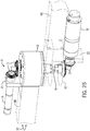
Fig. 2A , a system 1 for providing variable stiffness actuation may include avariable stiffness actuator 3 and acontroller 25. The system may further include arotary position sensor 27, which may provide input to thecontroller 25. Thevariable stiffness actuator 3 incorporates a selectable-rate spring 2, such as the embodiment of the selectable-rate spring 2 shown inFigs. 1A and 1B . Thevariable stiffness actuator 3 further comprises adrive motor 12 having arotatable drive shaft 9 connected to theconnection point 35 of theflexure bar 4. The rotation of therotational contactors 6 is driven by themotor 10 which is attached to one or more of therotational contactors 6 through themotor transmission system 14. Anactuator housing 15 surrounds the selectable-rate spring 2 and thetransmission system 14. Themotor 10 may connect to theactuator housing 15 via mountingplate 21. In the embodiment ofFig. 2 , theactuator housing 15 rotatably connects to each of therotational contactors 6 at a respective connection point 34 (Fig. 1A ). Theactuator housing 15 ofFigs. 2A-2B also connects to alink member 58 at the linkmember connection point 17. Theactuator housing 15 is adjacent to thefirst housing 62, which is connected to afirst member 60 atconnection point 19. - In the embodiment of the
variable stiffness actuator 3 depicted inFigs. 2A and2B , thedrive motor 12 drives the rotation of theactuator housing 15, which is connected to linkmember 58. For example, thedrive motor 12 functions to rotate thelink member 58 and theactuator housing 15 in therotational direction 37. Thedrive motor 12 connects to thefirst housing 62 via themotor mounting plate 22. Thus, such rotation is actuated with respect to thefirst member 60 andfirst housing 62. Thedrive motor 12 connects to therotatable drive shaft 9 via thedrive motor link 13. Thedrive shaft 9 then connects to theflexure bar 4. If the flexure bar is in contact with therotational contactors 6, then the rotation of theflexure bar 4 will cause rotation of theactuator housing 15. Namely, the one or morerotational contactors 6 are connected to thebottom plate 55 and/ortop plate 54 of theactuator housing 15, and thus any force imparted on therotational contactor 6 would be imparted to theactuator housing 15. If the one or morerotational contactors 6 are in an inward-most position, for example, then the selectable-rate spring 2 will be stiff and will impart all, or nearly all, of the motion from thedrive shaft 9 to theactuator housing 15. On the other hand, if the one or morerotational contactors 6 are in an outward-most position, and theflexure bar 4 rotates freely within a certain degree of motion, then none of the motion of thedrive shaft 9 will be imparted to theactuator housing 15 within that range of motion where theflexure bar 4 is not in contact with therotational contactor 6. It follows that the rotational contactor may be anywhere in between the inward-most and outward-most positions, and thus, due to the varying flex of theflexure bar 4, a varying amount of motion will be imparted from thedrive shaft 9 to theactuator housing 15. - The
controller 25 may be employed to control thedrive motor 12 and themotor 10 connected to the one or morerotational contactors 6. Such control may be feed-forward control, providing a control signal to thedrive motor 12 and/or themotor 10 controlling therotational contactors 6 in a predefined way. In other words, the controller may provide variable stiffness to the selectable-rate spring 2 according to a predefined program or plan. Alternatively, the controller may receive input from arotary position sensor 27 on theVSA 3 that provide position information of theactuator housing 15 relative to thedrive shaft 9 such that the controller can modify the stiffness program or the motion program according to whether the flex of theflexure bar 4 deviates from the programmed plan. For example, if the torque on the joint is causing more deflection of theflexure bar 4 than expected, the control program may be modified to account for the difference. -
Figs. 3A-3D show various embodiments of the selectable-rate spring 2. InFig. 3A , the selectable-rate spring 2 comprises fourrotational contactors 6 and aflexure bar 4. There, themotor 10 may drive all fourrotational contactors 6 simultaneously. Themotor transmission system 14 operates to impart rotational motion in the correct rotational direction 36 (Fig. 1B ) on each of therotational contactors 6. As described above, therotational contactors 6 rotate about axis ofrotation 32. Further, ataxis 32 therotational contactors 6 are connected to thebottom plate 55 of theactuator housing 15 at theconnection point 34 for eachrotational contactor 6. Thereby, the motion from theflexure bar 4 is transmitted to theactuator housing 15 at theconnection point 34 between therotational contactors 6 and thebottom plate 55 ortop plate 54 of theactuator housing 15. - In embodiments involving more than one rotational contactor driven by a
single motor 10, themotor 10 may act to rotate half of therotational contactors 6 in a clockwiserotational direction 36, while the other half is rotated in a counterclockwiserotational direction 36. As themotor 10 rotates therotational contactors 6, the angles θs of therotational contactors 6 change such that the magnitude of the angles θs of each of therotational contactors 6 is the same. Thus, when therotational contactors 6 are in a middle position, i.e., the central line of each set of rotational contactors align with one another and are perpendicular with the center line of theflexure bar 4, θs = 0. As dierotational contactors 6 are moved outward or inward, the magnitude of θs increases equally for all four rotational contactors. In other embodiments, each of therotational contactors 6 may be controlled individually, and thus the θs of the variousrotational contactors 6 may differ at any given time. - As described above, the
flexure bar 4 is driven bydrive motor 12. Depending on the position of therotational contactors 6, theflexure bar 4 may impart rotation on theactuator housing 15. The rotation imparted onactuator housing 15 may be measured as angle θp with respect to a particular position, such as the position of thefirst housing 62. In various embodiments, thevariable stiffness actuator 3 may be designed to provide 360° of motion, and thus θp may vary from 0 to 360. In other embodiments, thevariable stiffness actuator 3 may be designed to allow a more limited range of motion, which would limit the range of θp. -
Figs. 3B and 3C each show embodiments of selectable-rate springs 2 having tworotational contactors 6 positioned on opposite sides of the flexure bar. InFig. 3B , therotational contactors 6 are positioned on opposite sides of the drive shaft, or theconnection point 35 between theflexure bar 4 and thedrive shaft 9.Fig. 3C depicts an embodiment of the selectable-rate spring 2 having tworotational contactors 6 positioned on opposing sides of theflexure bar 4, but on the same side of theconnection point 35 to thedrive shaft 9. In both of the embodiments ofFigs. 3B and 3C , the selectable-rate spring 2 will provide variable stiffness in both the clockwise and counterclockwiserotational direction 37. Thus, through rotation of the tworotational contactors 6, the selectable-rate spring 2 can provide variation in the stiffness of the connection between thedrive shaft 9 and theactuator housing 15 in both circular directions. This is contrasted with the embodiment ofFig. 3D , in which the selectable-rate spring 2 provides stiffness variation in only one direction. - In the embodiment of
Fig. 3D , the selectable-rate spring 2 has only a singlerotational contactor 6. Therotational contactor 6 is positioned to allow variable stiffness in the counterclockwiserotational direction 37. Namely, therotational contactor 6 may rotate along theflexure bar 4 to increase or decrease the stiffness of the connection between theflexure bar 4 and therotational contactor 6 when theflexure bar 4 is pressed against thatrotational contactor 6. When rotational motion is imparted in the counterclockwise direction, theflexure bar 4 contacts thestop bar 65, which, does not move and thus provides a constant stiffness level. Thus, the embodiment ofFig. 3D may be employed where stiffness variation is only sought in one direction. Theimmobile stop bar 65 may be designed and positioned to provide any level of constant stiffness, from maximum stiffness to very low, or even zero stiffness. - One intended use of the presently disclosed
VSA 3 is for robotics applications in which a robot interacts with its environment, e.g., manufacturing tasks, any task that involves physical manipulation/interaction. Variable stiffness actuation will allow robots to provide high accuracy positioning in free space, like conventional manipulators, when joint stiffness is high. The stiffness of each joint will be able to be adjusted independently so that robots will be able to have directions of high stiffness and directions of low stiffness to perform useful work without damage to the robot or external structures or people. An example of constrained manipulation would be to use a robot to tighten a bolt. The robot must be stiff in the direction associated with advancing the bolt in the threaded hole, but compliant in the directions that are constrained by the wrench/bolt interaction that do not advance the bolt in the hole. - This written description uses examples to disclose the invention, including the best mode, and also to enable any person skilled in the art to make and use the invention. The patentable scope of the invention is defined by the claims, and may include other examples that occur to those skilled in the art. Such other examples are intended to be within the scope of the claims if they have structural elements that do not differ from the literal language of the claims, or if they include equivalent structural elements with insubstantial differences from the literal languages of the claims.
Claims (14)
- A selectable-rate spring (2), the selectable-rate spring (2) comprising:a flexure bar (4) connectable to a rotatable shaft (9), the flexure bar (4) having at least one arched portion (5);at least one rotational contactor (6, 42, 43, 44, 45) connectable to a link member (58), wherein the rotational contactor (6) rotates about an axis (32) while maintaining contact with the arched portion (5) of the flexure bar (4); characterised bya motor (12) connected to the at least one rotational contactor (6) so as to rotate the rotational contactor (6);wherein as the rotational contactor (6) rotates it changes a connection stiffness between the rotatable shaft (9) and the link member (58).
- The selectable-rate spring (2) of claim 1 further comprising a second arched portion of the flexure bar (4) and a second rotational contactor (43) connectable to the link member (58), wherein the second rotational contactor (43) rotates about a second axis (32) while maintaining contact with the second arched portion of the flexure bar (4).
- The selectable-rate spring (2) of claim 2 wherein the motor (12) is connected to the first and second rotational contactors (42, 43) so as to simultaneously rotate the rotational contactors (42, 43) in opposite rotational directions or wherein the first and second rotational contactors (42, 43) are positioned on opposite sides of the rotatable shaft (9).
- The selectable-rate spring (2) of claim 1 further comprising four rotational contactors (42, 43, 44, 45) connectable to the link member (58), wherein the flexure bar (4) has four arched portions and each rotational contactor (42, 43, 44, 45) rotates about a respective axis (32) while maintaining contact with a respective one of the four arched portions.
- The selectable-rate spring (2) of claims 1 or 4, wherein the at least one rotational contactor (6, 42, 43, 44, 45) when dependent on claim 1 or each of the four rotational contactors (42, 43, 44, 45) when dependent on claim 4 comprise at least one bearing (8) at a contact end (47) of the rotational contactor (6, 42, 43, 44, 45), wherein as the rotational contactor (6, 42, 43, 44, 45) rotates about the separate axis (32) the bearing (8) rolls along the respective arched portion of the flexure bar (4).
- The selectable-rate spring (2) of claim 5 when dependent on claim 4 further comprising a housing (15) surrounding the flexure bar (4) and the four rotational contactors (42, 43, 44, 45);
wherein the housing (15) provides a connection point to the link member (58) and wherein the four rotational contactors (42, 43, 44, 45) are rotatably connected to the housing (15). - The selectable-rate spring (2) of claim 1, wherein the flexure bar (4) is comprised of a superelastic alloy.
- A variable stiffness actuator comprising the selectable-rate spring (2) of claim 1, the variable stiffness actuator further comprising:
a drive motor (12) connected to the rotatable shaft. - The variable stiffness actuator of claim 8 further comprising a second arched portion of the flexure bar (4) and a second rotational contactor (43) connectable to the link member (58),
wherein the second rotational contactor (43) rotates about a second axis (32) while maintaining contact with the second arched portion of the flexure bar (4); and
wherein the at least two rotational contactors (42, 43) are positioned on opposing sides of the flexure bar (4), each rotating in opposite rotational directions about a separate axis (32) while maintaining contact with the respective arched portion of the flexure bar (4). - The variable stiffness actuator of claim 8, wherein the rotational contactor (42) has at least one bearing (8) at a contact end (47) thereof, wherein as the rotational contactor (42) rotates about the axis (32) the bearing (8) rolls along the arched portion of the flexure bar (4) or
wherein the variable stiffness actuator further comprises at least four rotational contractors (42, 43, 44, 45), each rotating about a separate axis (32) while maintaining contact with the respective arched portion of the flexure bar (4) or
wherein the variable stiffness actuator further comprises a housing (15) surrounding the flexure bar (4) and the rotational contactor (42, 43, 44, 45), wherein the housing (15) provides the connection between the link member (58) and the rotational contactor (42, 43, 44, 45) or
wherein the rotational contactor (42, 43, 44, 45) is directly rotatably connected to the link member (58). - The variable stiffness actuator of claim 9, wherein the at least two rotational contactors (42, 43) are positioned on opposing sides of the drive shaft (9).
- The variable stiffness actuator of claim 8, wherein the flexure bar comprises at least two arched portions,
the at least one rotational contactor (6, 42, 43, 44, 45) comprises at least two rotational contactors (42, 43) connected to a link member (58), the at least two rotational contactors (42, 43) each rotate about an axis (32) while maintaining contact with the flexure bar (4), and
the motor (12) is connected to the at least two rotational contactors (42, 43) so as to rotate the rotational contactors (42, 43) to vary a stiffness between the rotatable shaft (9) and the link member (58). - The variable stiffness actuator of claim 12, wherein the at least two rotational contactors (42, 43) are connected to the link member (58) via a housing (15), wherein the housing (15) surrounds the flexure bar (4) and the at least two rotational contactors (42, 43), and provides a connection point to the link member (58) and the rotational contactors (42, 43).
- The variable stiffness actuator of claim 13, wherein the motor (12) connected to the rotational contactors (42, 43) is mounted to the housing (15).
Applications Claiming Priority (2)
| Application Number | Priority Date | Filing Date | Title |
|---|---|---|---|
| US201361815485P | 2013-04-24 | 2013-04-24 | |
| PCT/US2014/035294 WO2014176423A1 (en) | 2013-04-24 | 2014-04-24 | Variable stiffness actuator with large range of stiffness |
Publications (3)
| Publication Number | Publication Date |
|---|---|
| EP2989345A1 EP2989345A1 (en) | 2016-03-02 |
| EP2989345A4 EP2989345A4 (en) | 2017-08-02 |
| EP2989345B1 true EP2989345B1 (en) | 2019-04-10 |
Family
ID=51792385
Family Applications (1)
| Application Number | Title | Priority Date | Filing Date |
|---|---|---|---|
| EP14788460.5A Active EP2989345B1 (en) | 2013-04-24 | 2014-04-24 | Variable stiffness actuator with large range of stiffness |
Country Status (6)
| Country | Link |
|---|---|
| US (1) | US9840012B2 (en) |
| EP (1) | EP2989345B1 (en) |
| JP (1) | JP6556697B2 (en) |
| CN (1) | CN105264255B (en) |
| CA (1) | CA2910565C (en) |
| WO (1) | WO2014176423A1 (en) |
Cited By (2)
| Publication number | Priority date | Publication date | Assignee | Title |
|---|---|---|---|---|
| DE102021000619B3 (en) | 2021-01-26 | 2021-12-30 | Technische Universität Chemnitz | Non-linear elastic joint with an elastic mechanism and drives |
| US11654584B2 (en) | 2021-06-18 | 2023-05-23 | Industrial Technology Research Institute | Actuator |
Families Citing this family (34)
| Publication number | Priority date | Publication date | Assignee | Title |
|---|---|---|---|---|
| US10611020B2 (en) | 2013-12-19 | 2020-04-07 | Roam Robotics Inc. | Pneumatic exomuscle system and method |
| US9676104B2 (en) | 2014-05-19 | 2017-06-13 | Yaskawa America, Inc. | Variable spring constant torque coupler |
| KR101807365B1 (en) * | 2014-11-19 | 2017-12-08 | 국립암센터 | Apparatus for controlling Stiffness of output member for rotary motion and translational motion |
| CN104647397B (en) * | 2015-03-17 | 2016-02-03 | 河北工业大学 | A kind of flexible joint of stiffness variable |
| WO2016160624A1 (en) | 2015-03-27 | 2016-10-06 | Other Lab Llc | Lower-leg exoskeleton system and method |
| CN109476023B (en) * | 2016-04-14 | 2020-04-14 | 马凯特大学 | Variable Stiffness Tandem Elastic Actuator |
| TWI592588B (en) | 2016-07-12 | 2017-07-21 | 財團法人工業技術研究院 | Electromagnetic spring and elastic actuator having the same |
| CN106239554B (en) * | 2016-10-10 | 2024-03-15 | 中国科学院宁波材料技术与工程研究所 | A variable stiffness transmission mechanism and robot joint |
| WO2018096679A1 (en) * | 2016-11-28 | 2018-05-31 | オリンパス株式会社 | Variable rigidity device |
| ES2969892T3 (en) | 2017-02-03 | 2024-05-23 | Roam Robotics Inc | System and method for user intent recognition |
| CN108621123B (en) * | 2017-03-23 | 2020-09-08 | 台达电子工业股份有限公司 | Passive compliance mechanism |
| TWI593527B (en) * | 2017-03-23 | 2017-08-01 | 台達電子工業股份有限公司 | Passive compliant mechanism |
| JP7475143B2 (en) * | 2017-04-13 | 2024-04-26 | ローム ロボティクス インコーポレイテッド | Leg Exoskeleton System and Method |
| US10870202B2 (en) * | 2017-08-23 | 2020-12-22 | Board Of Regents, The University Of Texas System | Variable stiffness actuator with electrically modulated stiffness |
| IL272623B2 (en) | 2017-08-29 | 2024-12-01 | Roam Robotics Inc | System and method for detecting semi-guided intent |
| CA3072504A1 (en) * | 2017-08-29 | 2019-03-07 | Roam Robotics Inc. | Exoskeleton fit evaluation system and method |
| JP6581235B1 (en) * | 2018-03-30 | 2019-09-25 | 本田技研工業株式会社 | Link mechanism |
| IT201800006209A1 (en) * | 2018-06-11 | 2019-12-11 | Rotary joint with adjustable stiffness | |
| CN108748254A (en) * | 2018-06-20 | 2018-11-06 | 哈尔滨工业大学 | A kind of drive lacking variation rigidity manipulator based on variation rigidity elastic joint |
| CN109085382B (en) * | 2018-06-29 | 2019-11-12 | 华中科技大学 | An acceleration-sensitive mechanism based on mechanical metamaterials and a composite-sensitivity micromachined accelerometer |
| CN108942908B (en) * | 2018-08-03 | 2020-09-22 | 燕山大学 | A rotary joint variable stiffness actuator |
| CN109623871B (en) * | 2019-03-01 | 2023-05-23 | 河北工业大学 | An active-passive variable stiffness joint and its stiffness adjustment method |
| US11434973B2 (en) | 2019-04-10 | 2022-09-06 | Ohio University | Passive variable stiffness device for vibration isolation |
| CN110434879B (en) * | 2019-07-26 | 2020-10-30 | 华中科技大学 | Intelligent bionic separation and pickup device, manufacturing method and separation and pickup method |
| CN110861121B (en) * | 2019-10-16 | 2022-08-23 | 山东卡耐斯智能装备有限公司 | Flexible robot joint based on variable rigidity |
| ES3039928T3 (en) | 2019-12-13 | 2025-10-27 | Roam Robotics Inc | Powered device to benefit a wearer during skiing |
| IL295817A (en) | 2020-02-25 | 2022-10-01 | Roam Robotics Inc | Fluidic actuator systems and methods for mobile robots |
| CN111580464B (en) * | 2020-05-20 | 2021-06-29 | 南京航空航天大学 | Analytical method for forming trajectory of multi-roller free-bending three-dimensional constant-curvature components |
| US12514775B2 (en) | 2020-05-27 | 2026-01-06 | Roam Robotics Inc. | Powered medical device and methods for improved user mobility and treatment |
| CN115916472A (en) | 2020-05-27 | 2023-04-04 | 漫游机械人技术公司 | Fitting and suspension systems and methods for mobile robots |
| US12466060B2 (en) | 2021-08-17 | 2025-11-11 | Roam Robotics Inc. | Mobile power source for a mobile robot |
| JP2024534808A (en) | 2021-08-17 | 2024-09-26 | ローム ロボティクス インコーポレイテッド | Maritime Applications for Mobile Robots |
| WO2023023564A1 (en) | 2021-08-17 | 2023-02-23 | Roam Robotics Inc. | Unified pneumatic and electrical connector system and method |
| US12128553B2 (en) | 2022-10-18 | 2024-10-29 | Khalifa University of Science and Technology | Infinite-rotation infinite-stiffness variable stiffness actuator (IRISVSA) with application for compliant supernumerary robotic limb |
Family Cites Families (14)
| Publication number | Priority date | Publication date | Assignee | Title |
|---|---|---|---|---|
| GB191225725A (en) * | 1912-11-09 | 1913-10-16 | William James | Improvements in Carburettors for Internal Combustion Engines, and similar purposes. |
| GB726635A (en) * | 1952-11-13 | 1955-03-23 | Saurer Ag Adolph | Improvements in resilient couplings for shafts |
| DE2246661A1 (en) * | 1972-09-22 | 1974-03-28 | Porsche Ag | STEERING ARRANGEMENT FOR MOTOR VEHICLES |
| DE2950255C2 (en) * | 1979-12-13 | 1982-11-18 | Hackforth GmbH & Co KG, 4690 Herne | Elastic steel spring shaft coupling with fluid damping |
| JPH0351528Y2 (en) * | 1986-07-21 | 1991-11-06 | ||
| RU1773292C (en) * | 1990-08-06 | 1992-10-30 | Днепродзержинский Индустриальный Институт Им.М.И.Арсеничева | Flexible coupling |
| US5443247A (en) * | 1994-05-20 | 1995-08-22 | The United States Of America As Represented By The Administrator, National Aeronautics And Space Administration | Tuneable rotating unbalanced mass device |
| DE19734322B4 (en) | 1997-08-08 | 2004-05-27 | Zf Sachs Ag | Torsional vibration damper with rolling elements as coupling elements |
| ES2166234B1 (en) * | 1998-11-18 | 2003-02-16 | Eads Constr Aeronauticas Sa | A SYSTEM OF MODIFICATION OF THE PROPERTIES OF RIGIDITY / AMORTIGUATION OF STRUCTURAL UNIONS. |
| DE102009003008A1 (en) * | 2009-04-24 | 2010-11-25 | MÜLLER, Andreas | Device for changing a leaf spring characteristic |
| BR112012019608A2 (en) * | 2010-02-16 | 2017-08-29 | Bell Helicopter Textron Inc | LIQUID INERTIA VIBRATION ELIMINATOR WITH VARIABLE RIGIDITY |
| TWI419778B (en) * | 2011-03-16 | 2013-12-21 | Ind Tech Res Inst | Compliance joint device |
| US20130079160A1 (en) * | 2011-09-27 | 2013-03-28 | Caterpillar Inc. | Variable stiffness torsional coupling and machine using same |
| DE102013204588A1 (en) * | 2013-03-15 | 2014-09-18 | Siemens Aktiengesellschaft | Torque transmission device, actuator, robot |
-
2014
- 2014-04-24 WO PCT/US2014/035294 patent/WO2014176423A1/en not_active Ceased
- 2014-04-24 EP EP14788460.5A patent/EP2989345B1/en active Active
- 2014-04-24 US US14/786,881 patent/US9840012B2/en active Active
- 2014-04-24 CN CN201480023936.4A patent/CN105264255B/en active Active
- 2014-04-24 CA CA2910565A patent/CA2910565C/en active Active
- 2014-04-24 JP JP2016510782A patent/JP6556697B2/en active Active
Non-Patent Citations (1)
| Title |
|---|
| None * |
Cited By (3)
| Publication number | Priority date | Publication date | Assignee | Title |
|---|---|---|---|---|
| DE102021000619B3 (en) | 2021-01-26 | 2021-12-30 | Technische Universität Chemnitz | Non-linear elastic joint with an elastic mechanism and drives |
| WO2022161907A1 (en) | 2021-01-26 | 2022-08-04 | Technische Universität Chemnitz | Nonlinear elastic joint with an elastic mechanism and drives |
| US11654584B2 (en) | 2021-06-18 | 2023-05-23 | Industrial Technology Research Institute | Actuator |
Also Published As
| Publication number | Publication date |
|---|---|
| JP2016522366A (en) | 2016-07-28 |
| CN105264255A (en) | 2016-01-20 |
| CN105264255B (en) | 2018-05-04 |
| CA2910565A1 (en) | 2014-10-30 |
| JP6556697B2 (en) | 2019-08-07 |
| EP2989345A4 (en) | 2017-08-02 |
| US9840012B2 (en) | 2017-12-12 |
| EP2989345A1 (en) | 2016-03-02 |
| US20160082603A1 (en) | 2016-03-24 |
| CA2910565C (en) | 2020-04-14 |
| WO2014176423A1 (en) | 2014-10-30 |
Similar Documents
| Publication | Publication Date | Title |
|---|---|---|
| EP2989345B1 (en) | Variable stiffness actuator with large range of stiffness | |
| CN109476023B (en) | Variable Stiffness Tandem Elastic Actuator | |
| CN106363662B (en) | Plane deflection element and the actuator for using them | |
| US20170241497A1 (en) | Planar Torsion Spring for Knee Prostheses and Exoskeletons | |
| US10399219B2 (en) | Concentric opposed cam actuator | |
| Lauzier et al. | Series clutch actuators for safe physical human-robot interaction | |
| Schimmels et al. | The Arched Flexure VSA: A compact variable stiffness actuator with large stiffness range | |
| JP2021024061A (en) | Link operation device | |
| Tao et al. | A new variable stiffness robot joint | |
| Lan et al. | Design of adjustable constant-force forceps for robot-assisted surgical manipulation | |
| US11999049B2 (en) | Tactile feedback of an end effector of a robot manipulator over different orientation ranges | |
| JP2017164832A (en) | Robot hand, robot hand control program, and robot apparatus | |
| JP6559180B2 (en) | Robot hand, robot apparatus, robot hand control method, control program, and recording medium | |
| Medina et al. | Design and characterization of a novel mechanism of multiple joint stiffness (MMJS) | |
| Jeong et al. | Dual-mode variable stiffness actuator using two-stage worm gear transmission for safe robotic manipulators | |
| Li et al. | Design and analysis of a new 3-DOF compliant parallel positioning platform for nanomanipulation | |
| Grames et al. | A meso-scale rolling-contact gripping mechanism for robotic surgery | |
| Kim et al. | Vibration mechanism of constrained spatial flexible manipulators | |
| JP2006231454A (en) | Articulated arm mechanism | |
| JP6963310B2 (en) | Actuator and actuator operation control method | |
| CN108032331B (en) | A kind of variation rigidity flexible mechanical arm | |
| JP2011255485A (en) | Parallel mechanism and positioning system using the same | |
| Jafari et al. | Minimizing energy consumption through optimal mechanical design and stiffness regulation | |
| Swanson et al. | Bendy ARM 2.0: Continuum Arm Manipulator Refinement and Control for Assistive Technology |
Legal Events
| Date | Code | Title | Description |
|---|---|---|---|
| PUAI | Public reference made under article 153(3) epc to a published international application that has entered the european phase |
Free format text: ORIGINAL CODE: 0009012 |
|
| 17P | Request for examination filed |
Effective date: 20151022 |
|
| AK | Designated contracting states |
Kind code of ref document: A1 Designated state(s): AL AT BE BG CH CY CZ DE DK EE ES FI FR GB GR HR HU IE IS IT LI LT LU LV MC MK MT NL NO PL PT RO RS SE SI SK SM TR |
|
| AX | Request for extension of the european patent |
Extension state: BA ME |
|
| DAX | Request for extension of the european patent (deleted) | ||
| A4 | Supplementary search report drawn up and despatched |
Effective date: 20170705 |
|
| RIC1 | Information provided on ipc code assigned before grant |
Ipc: B25J 9/12 20060101ALI20170629BHEP Ipc: F16F 1/22 20060101ALI20170629BHEP Ipc: B25J 19/00 20060101ALI20170629BHEP Ipc: B25J 19/06 20060101AFI20170629BHEP Ipc: B25J 9/10 20060101ALI20170629BHEP Ipc: F16D 3/56 20060101ALI20170629BHEP |
|
| REG | Reference to a national code |
Ref country code: DE Ref legal event code: R079 Ref document number: 602014044530 Country of ref document: DE Free format text: PREVIOUS MAIN CLASS: F16F0001220000 Ipc: B25J0019060000 |
|
| RIC1 | Information provided on ipc code assigned before grant |
Ipc: B25J 19/06 20060101AFI20180903BHEP Ipc: B25J 19/00 20060101ALI20180903BHEP Ipc: F16D 3/56 20060101ALI20180903BHEP Ipc: B25J 9/12 20060101ALI20180903BHEP Ipc: F16F 1/22 20060101ALI20180903BHEP Ipc: B25J 9/10 20060101ALI20180903BHEP |
|
| GRAP | Despatch of communication of intention to grant a patent |
Free format text: ORIGINAL CODE: EPIDOSNIGR1 |
|
| STAA | Information on the status of an ep patent application or granted ep patent |
Free format text: STATUS: GRANT OF PATENT IS INTENDED |
|
| INTG | Intention to grant announced |
Effective date: 20181015 |
|
| GRAS | Grant fee paid |
Free format text: ORIGINAL CODE: EPIDOSNIGR3 |
|
| GRAJ | Information related to disapproval of communication of intention to grant by the applicant or resumption of examination proceedings by the epo deleted |
Free format text: ORIGINAL CODE: EPIDOSDIGR1 |
|
| GRAL | Information related to payment of fee for publishing/printing deleted |
Free format text: ORIGINAL CODE: EPIDOSDIGR3 |
|
| STAA | Information on the status of an ep patent application or granted ep patent |
Free format text: STATUS: REQUEST FOR EXAMINATION WAS MADE |
|
| GRAR | Information related to intention to grant a patent recorded |
Free format text: ORIGINAL CODE: EPIDOSNIGR71 |
|
| STAA | Information on the status of an ep patent application or granted ep patent |
Free format text: STATUS: GRANT OF PATENT IS INTENDED |
|
| GRAA | (expected) grant |
Free format text: ORIGINAL CODE: 0009210 |
|
| STAA | Information on the status of an ep patent application or granted ep patent |
Free format text: STATUS: THE PATENT HAS BEEN GRANTED |
|
| INTC | Intention to grant announced (deleted) | ||
| AK | Designated contracting states |
Kind code of ref document: B1 Designated state(s): AL AT BE BG CH CY CZ DE DK EE ES FI FR GB GR HR HU IE IS IT LI LT LU LV MC MK MT NL NO PL PT RO RS SE SI SK SM TR |
|
| INTG | Intention to grant announced |
Effective date: 20190301 |
|
| REG | Reference to a national code |
Ref country code: GB Ref legal event code: FG4D |
|
| REG | Reference to a national code |
Ref country code: CH Ref legal event code: EP Ref country code: AT Ref legal event code: REF Ref document number: 1118040 Country of ref document: AT Kind code of ref document: T Effective date: 20190415 |
|
| REG | Reference to a national code |
Ref country code: DE Ref legal event code: R096 Ref document number: 602014044530 Country of ref document: DE |
|
| REG | Reference to a national code |
Ref country code: IE Ref legal event code: FG4D |
|
| REG | Reference to a national code |
Ref country code: NL Ref legal event code: FP |
|
| REG | Reference to a national code |
Ref country code: LT Ref legal event code: MG4D |
|
| REG | Reference to a national code |
Ref country code: AT Ref legal event code: MK05 Ref document number: 1118040 Country of ref document: AT Kind code of ref document: T Effective date: 20190410 |
|
| PG25 | Lapsed in a contracting state [announced via postgrant information from national office to epo] |
Ref country code: AL Free format text: LAPSE BECAUSE OF FAILURE TO SUBMIT A TRANSLATION OF THE DESCRIPTION OR TO PAY THE FEE WITHIN THE PRESCRIBED TIME-LIMIT Effective date: 20190410 Ref country code: ES Free format text: LAPSE BECAUSE OF FAILURE TO SUBMIT A TRANSLATION OF THE DESCRIPTION OR TO PAY THE FEE WITHIN THE PRESCRIBED TIME-LIMIT Effective date: 20190410 Ref country code: LT Free format text: LAPSE BECAUSE OF FAILURE TO SUBMIT A TRANSLATION OF THE DESCRIPTION OR TO PAY THE FEE WITHIN THE PRESCRIBED TIME-LIMIT Effective date: 20190410 Ref country code: PT Free format text: LAPSE BECAUSE OF FAILURE TO SUBMIT A TRANSLATION OF THE DESCRIPTION OR TO PAY THE FEE WITHIN THE PRESCRIBED TIME-LIMIT Effective date: 20190910 Ref country code: NO Free format text: LAPSE BECAUSE OF FAILURE TO SUBMIT A TRANSLATION OF THE DESCRIPTION OR TO PAY THE FEE WITHIN THE PRESCRIBED TIME-LIMIT Effective date: 20190710 Ref country code: HR Free format text: LAPSE BECAUSE OF FAILURE TO SUBMIT A TRANSLATION OF THE DESCRIPTION OR TO PAY THE FEE WITHIN THE PRESCRIBED TIME-LIMIT Effective date: 20190410 Ref country code: SE Free format text: LAPSE BECAUSE OF FAILURE TO SUBMIT A TRANSLATION OF THE DESCRIPTION OR TO PAY THE FEE WITHIN THE PRESCRIBED TIME-LIMIT Effective date: 20190410 Ref country code: FI Free format text: LAPSE BECAUSE OF FAILURE TO SUBMIT A TRANSLATION OF THE DESCRIPTION OR TO PAY THE FEE WITHIN THE PRESCRIBED TIME-LIMIT Effective date: 20190410 |
|
| PG25 | Lapsed in a contracting state [announced via postgrant information from national office to epo] |
Ref country code: RS Free format text: LAPSE BECAUSE OF FAILURE TO SUBMIT A TRANSLATION OF THE DESCRIPTION OR TO PAY THE FEE WITHIN THE PRESCRIBED TIME-LIMIT Effective date: 20190410 Ref country code: LV Free format text: LAPSE BECAUSE OF FAILURE TO SUBMIT A TRANSLATION OF THE DESCRIPTION OR TO PAY THE FEE WITHIN THE PRESCRIBED TIME-LIMIT Effective date: 20190410 Ref country code: GR Free format text: LAPSE BECAUSE OF FAILURE TO SUBMIT A TRANSLATION OF THE DESCRIPTION OR TO PAY THE FEE WITHIN THE PRESCRIBED TIME-LIMIT Effective date: 20190711 Ref country code: PL Free format text: LAPSE BECAUSE OF FAILURE TO SUBMIT A TRANSLATION OF THE DESCRIPTION OR TO PAY THE FEE WITHIN THE PRESCRIBED TIME-LIMIT Effective date: 20190410 Ref country code: BG Free format text: LAPSE BECAUSE OF FAILURE TO SUBMIT A TRANSLATION OF THE DESCRIPTION OR TO PAY THE FEE WITHIN THE PRESCRIBED TIME-LIMIT Effective date: 20190710 |
|
| REG | Reference to a national code |
Ref country code: CH Ref legal event code: PL |
|
| REG | Reference to a national code |
Ref country code: BE Ref legal event code: MM Effective date: 20190430 |
|
| PG25 | Lapsed in a contracting state [announced via postgrant information from national office to epo] |
Ref country code: IS Free format text: LAPSE BECAUSE OF FAILURE TO SUBMIT A TRANSLATION OF THE DESCRIPTION OR TO PAY THE FEE WITHIN THE PRESCRIBED TIME-LIMIT Effective date: 20190810 Ref country code: AT Free format text: LAPSE BECAUSE OF FAILURE TO SUBMIT A TRANSLATION OF THE DESCRIPTION OR TO PAY THE FEE WITHIN THE PRESCRIBED TIME-LIMIT Effective date: 20190410 Ref country code: LU Free format text: LAPSE BECAUSE OF NON-PAYMENT OF DUE FEES Effective date: 20190424 |
|
| REG | Reference to a national code |
Ref country code: DE Ref legal event code: R097 Ref document number: 602014044530 Country of ref document: DE |
|
| PG25 | Lapsed in a contracting state [announced via postgrant information from national office to epo] |
Ref country code: CH Free format text: LAPSE BECAUSE OF NON-PAYMENT OF DUE FEES Effective date: 20190430 Ref country code: MC Free format text: LAPSE BECAUSE OF FAILURE TO SUBMIT A TRANSLATION OF THE DESCRIPTION OR TO PAY THE FEE WITHIN THE PRESCRIBED TIME-LIMIT Effective date: 20190410 Ref country code: CZ Free format text: LAPSE BECAUSE OF FAILURE TO SUBMIT A TRANSLATION OF THE DESCRIPTION OR TO PAY THE FEE WITHIN THE PRESCRIBED TIME-LIMIT Effective date: 20190410 Ref country code: LI Free format text: LAPSE BECAUSE OF NON-PAYMENT OF DUE FEES Effective date: 20190430 Ref country code: RO Free format text: LAPSE BECAUSE OF FAILURE TO SUBMIT A TRANSLATION OF THE DESCRIPTION OR TO PAY THE FEE WITHIN THE PRESCRIBED TIME-LIMIT Effective date: 20190410 Ref country code: SK Free format text: LAPSE BECAUSE OF FAILURE TO SUBMIT A TRANSLATION OF THE DESCRIPTION OR TO PAY THE FEE WITHIN THE PRESCRIBED TIME-LIMIT Effective date: 20190410 Ref country code: EE Free format text: LAPSE BECAUSE OF FAILURE TO SUBMIT A TRANSLATION OF THE DESCRIPTION OR TO PAY THE FEE WITHIN THE PRESCRIBED TIME-LIMIT Effective date: 20190410 Ref country code: DK Free format text: LAPSE BECAUSE OF FAILURE TO SUBMIT A TRANSLATION OF THE DESCRIPTION OR TO PAY THE FEE WITHIN THE PRESCRIBED TIME-LIMIT Effective date: 20190410 |
|
| PLBE | No opposition filed within time limit |
Free format text: ORIGINAL CODE: 0009261 |
|
| STAA | Information on the status of an ep patent application or granted ep patent |
Free format text: STATUS: NO OPPOSITION FILED WITHIN TIME LIMIT |
|
| PG25 | Lapsed in a contracting state [announced via postgrant information from national office to epo] |
Ref country code: BE Free format text: LAPSE BECAUSE OF NON-PAYMENT OF DUE FEES Effective date: 20190430 Ref country code: SM Free format text: LAPSE BECAUSE OF FAILURE TO SUBMIT A TRANSLATION OF THE DESCRIPTION OR TO PAY THE FEE WITHIN THE PRESCRIBED TIME-LIMIT Effective date: 20190410 |
|
| 26N | No opposition filed |
Effective date: 20200113 |
|
| PG25 | Lapsed in a contracting state [announced via postgrant information from national office to epo] |
Ref country code: TR Free format text: LAPSE BECAUSE OF FAILURE TO SUBMIT A TRANSLATION OF THE DESCRIPTION OR TO PAY THE FEE WITHIN THE PRESCRIBED TIME-LIMIT Effective date: 20190410 |
|
| PG25 | Lapsed in a contracting state [announced via postgrant information from national office to epo] |
Ref country code: IE Free format text: LAPSE BECAUSE OF NON-PAYMENT OF DUE FEES Effective date: 20190424 |
|
| PG25 | Lapsed in a contracting state [announced via postgrant information from national office to epo] |
Ref country code: SI Free format text: LAPSE BECAUSE OF FAILURE TO SUBMIT A TRANSLATION OF THE DESCRIPTION OR TO PAY THE FEE WITHIN THE PRESCRIBED TIME-LIMIT Effective date: 20190410 |
|
| PG25 | Lapsed in a contracting state [announced via postgrant information from national office to epo] |
Ref country code: CY Free format text: LAPSE BECAUSE OF FAILURE TO SUBMIT A TRANSLATION OF THE DESCRIPTION OR TO PAY THE FEE WITHIN THE PRESCRIBED TIME-LIMIT Effective date: 20190410 |
|
| PG25 | Lapsed in a contracting state [announced via postgrant information from national office to epo] |
Ref country code: MT Free format text: LAPSE BECAUSE OF FAILURE TO SUBMIT A TRANSLATION OF THE DESCRIPTION OR TO PAY THE FEE WITHIN THE PRESCRIBED TIME-LIMIT Effective date: 20190410 Ref country code: HU Free format text: LAPSE BECAUSE OF FAILURE TO SUBMIT A TRANSLATION OF THE DESCRIPTION OR TO PAY THE FEE WITHIN THE PRESCRIBED TIME-LIMIT; INVALID AB INITIO Effective date: 20140424 |
|
| PG25 | Lapsed in a contracting state [announced via postgrant information from national office to epo] |
Ref country code: MK Free format text: LAPSE BECAUSE OF FAILURE TO SUBMIT A TRANSLATION OF THE DESCRIPTION OR TO PAY THE FEE WITHIN THE PRESCRIBED TIME-LIMIT Effective date: 20190410 |
|
| P01 | Opt-out of the competence of the unified patent court (upc) registered |
Effective date: 20230816 |
|
| PGFP | Annual fee paid to national office [announced via postgrant information from national office to epo] |
Ref country code: NL Payment date: 20250427 Year of fee payment: 12 |
|
| PGFP | Annual fee paid to national office [announced via postgrant information from national office to epo] |
Ref country code: DE Payment date: 20250429 Year of fee payment: 12 |
|
| PGFP | Annual fee paid to national office [announced via postgrant information from national office to epo] |
Ref country code: GB Payment date: 20250428 Year of fee payment: 12 |
|
| PGFP | Annual fee paid to national office [announced via postgrant information from national office to epo] |
Ref country code: IT Payment date: 20250422 Year of fee payment: 12 |
|
| PGFP | Annual fee paid to national office [announced via postgrant information from national office to epo] |
Ref country code: FR Payment date: 20250425 Year of fee payment: 12 |