EP2989310B1 - Gasturbinen gekoppeltes speichersystem zur ansaugfluidvorwärmung - Google Patents
Gasturbinen gekoppeltes speichersystem zur ansaugfluidvorwärmung Download PDFInfo
- Publication number
- EP2989310B1 EP2989310B1 EP14724378.6A EP14724378A EP2989310B1 EP 2989310 B1 EP2989310 B1 EP 2989310B1 EP 14724378 A EP14724378 A EP 14724378A EP 2989310 B1 EP2989310 B1 EP 2989310B1
- Authority
- EP
- European Patent Office
- Prior art keywords
- heat
- gas turbine
- fluid
- compressor
- heat accumulator
- Prior art date
- Legal status (The legal status is an assumption and is not a legal conclusion. Google has not performed a legal analysis and makes no representation as to the accuracy of the status listed.)
- Active
Links
Images
Classifications
-
- F—MECHANICAL ENGINEERING; LIGHTING; HEATING; WEAPONS; BLASTING
- F02—COMBUSTION ENGINES; HOT-GAS OR COMBUSTION-PRODUCT ENGINE PLANTS
- F02C—GAS-TURBINE PLANTS; AIR INTAKES FOR JET-PROPULSION PLANTS; CONTROLLING FUEL SUPPLY IN AIR-BREATHING JET-PROPULSION PLANTS
- F02C6/00—Plural gas-turbine plants; Combinations of gas-turbine plants with other apparatus; Adaptations of gas-turbine plants for special use
- F02C6/14—Gas-turbine plants having means for storing energy, e.g. for meeting peak loads
-
- F—MECHANICAL ENGINEERING; LIGHTING; HEATING; WEAPONS; BLASTING
- F02—COMBUSTION ENGINES; HOT-GAS OR COMBUSTION-PRODUCT ENGINE PLANTS
- F02C—GAS-TURBINE PLANTS; AIR INTAKES FOR JET-PROPULSION PLANTS; CONTROLLING FUEL SUPPLY IN AIR-BREATHING JET-PROPULSION PLANTS
- F02C7/00—Features, components parts, details or accessories, not provided for in, or of interest apart form groups F02C1/00 - F02C6/00; Air intakes for jet-propulsion plants
- F02C7/08—Heating air supply before combustion, e.g. by exhaust gases
-
- F—MECHANICAL ENGINEERING; LIGHTING; HEATING; WEAPONS; BLASTING
- F02—COMBUSTION ENGINES; HOT-GAS OR COMBUSTION-PRODUCT ENGINE PLANTS
- F02C—GAS-TURBINE PLANTS; AIR INTAKES FOR JET-PROPULSION PLANTS; CONTROLLING FUEL SUPPLY IN AIR-BREATHING JET-PROPULSION PLANTS
- F02C7/00—Features, components parts, details or accessories, not provided for in, or of interest apart form groups F02C1/00 - F02C6/00; Air intakes for jet-propulsion plants
- F02C7/08—Heating air supply before combustion, e.g. by exhaust gases
- F02C7/10—Heating air supply before combustion, e.g. by exhaust gases by means of regenerative heat-exchangers
-
- F—MECHANICAL ENGINEERING; LIGHTING; HEATING; WEAPONS; BLASTING
- F02—COMBUSTION ENGINES; HOT-GAS OR COMBUSTION-PRODUCT ENGINE PLANTS
- F02C—GAS-TURBINE PLANTS; AIR INTAKES FOR JET-PROPULSION PLANTS; CONTROLLING FUEL SUPPLY IN AIR-BREATHING JET-PROPULSION PLANTS
- F02C7/00—Features, components parts, details or accessories, not provided for in, or of interest apart form groups F02C1/00 - F02C6/00; Air intakes for jet-propulsion plants
- F02C7/32—Arrangement, mounting, or driving, of auxiliaries
-
- F—MECHANICAL ENGINEERING; LIGHTING; HEATING; WEAPONS; BLASTING
- F05—INDEXING SCHEMES RELATING TO ENGINES OR PUMPS IN VARIOUS SUBCLASSES OF CLASSES F01-F04
- F05D—INDEXING SCHEME FOR ASPECTS RELATING TO NON-POSITIVE-DISPLACEMENT MACHINES OR ENGINES, GAS-TURBINES OR JET-PROPULSION PLANTS
- F05D2220/00—Application
- F05D2220/30—Application in turbines
- F05D2220/32—Application in turbines in gas turbines
-
- F—MECHANICAL ENGINEERING; LIGHTING; HEATING; WEAPONS; BLASTING
- F05—INDEXING SCHEMES RELATING TO ENGINES OR PUMPS IN VARIOUS SUBCLASSES OF CLASSES F01-F04
- F05D—INDEXING SCHEME FOR ASPECTS RELATING TO NON-POSITIVE-DISPLACEMENT MACHINES OR ENGINES, GAS-TURBINES OR JET-PROPULSION PLANTS
- F05D2260/00—Function
- F05D2260/42—Storage of energy
-
- Y—GENERAL TAGGING OF NEW TECHNOLOGICAL DEVELOPMENTS; GENERAL TAGGING OF CROSS-SECTIONAL TECHNOLOGIES SPANNING OVER SEVERAL SECTIONS OF THE IPC; TECHNICAL SUBJECTS COVERED BY FORMER USPC CROSS-REFERENCE ART COLLECTIONS [XRACs] AND DIGESTS
- Y02—TECHNOLOGIES OR APPLICATIONS FOR MITIGATION OR ADAPTATION AGAINST CLIMATE CHANGE
- Y02E—REDUCTION OF GREENHOUSE GAS [GHG] EMISSIONS, RELATED TO ENERGY GENERATION, TRANSMISSION OR DISTRIBUTION
- Y02E20/00—Combustion technologies with mitigation potential
- Y02E20/14—Combined heat and power generation [CHP]
Definitions
- the present invention relates to a storage system coupled to gas turbines for storing thermal energy in a heat storage device for preheating a fluid fed to an intake side of a gas turbine, as well as a method for operating such a storage system.
- Such a storage system coupled to a gas turbine is from, for example US 2011/0094236 A1 known. It is proposed therein to store compressor air in a cavern if there is an excess flow. Before the storage process in the cavern, heat is extracted from the compressor air in order to then supply this heat to the compressor air again when it is removed from the cavern and fed to a combustion chamber of a gas turbine.
- gas-fired power plants or combined gas and steam power plants are increasingly used only as reserve power plants or for network stabilization.
- These power plants are operated by renewable energy sources, in particular at times when the energy supply is low, in order to ensure the electrical energy supply.
- these power plants are increasingly operated at partial load, i.e. in a load condition for which the power plants are usually not optimally designed. Due to the sub-optimal technical design of gas turbines, the fuel-related efficiency in partial load operation is lower than in full load.
- the object of the present invention is therefore to propose a gas turbine system which allows improved partial load operation.
- a gas turbine-coupled storage system for storing thermal energy in a heat store, with a charging circuit and a discharging circuit
- the charging circuit having an electrically operated heat generating device is provided, which is designed to generate heat using electrical energy
- the charging circuit is designed to at least partially transfer this heat to the heat accumulator in order to store it therein
- the discharge circuit is designed to by means of to thermally condition a fluid from the heat from the heat accumulator in order to then lead it to the intake side of a compressor of a gas turbine
- the charging circuit has a heat pump as a heat generating device.
- the storage system coupled to the gas turbine thus provides a heat storage device which can be charged with thermal energy with the aid of a charging circuit.
- the thermal energy comes from an electrically operated heat generating device.
- the electrical operation of the heat generating device proves to be particularly advantageous in that no energy has to be taken from a thermal power plant circuit during the charging or discharging of the heat accumulator, which, for example, could adversely affect the energy generation efficiency in a power plant. Rather, the heat generating device generates thermal energy by converting electrical energy, which can then be temporarily stored with the aid of the heat accumulator in order to use it at a later point in time if required can. It proves to be particularly advantageous in particular to convert electrical energy into heat at a point in time when, for example, there is an excess of it, for example when there is an excess of electrical energy in the power supply networks.
- the thermal energy temporarily stored in the heat accumulator can now be transferred to a fluid by means of the discharge circuit, which is then fed to the suction side of the compressor of the gas turbine. Because of this preheating of the fluid introduced into the compressor of the gas turbine, the furnace temperature in the gas turbine can be increased, as a result of which a higher useful energy yield can also be expected. For example, the expansion of exhaust gas at a higher temperature in the expansion turbine with unchanged fuel consumption, an increased work performance can be expected. Conversely, fuel for combustion in the gas turbine can be saved with the same output. If, in addition, the thermal energy of the exhaust gas emerging from the gas turbine after combustion is used in a further thermal process, this can also be operated with a higher degree of efficiency. For example, a steam part of a coupled gas and steam power plant that is coupled to the gas turbine can be operated with increased efficiency.
- the charging circuit has a heat pump as a heat generating device.
- This heat pump is designed in particular to be provided with a heat supply line for low-temperature heat flows in order to condition a heat flow that is in the low-temperature range with regard to its heat content.
- Such low-temperature heat flows can, for example, be taken from district heating networks or from waste heat pipes of an industrial plant.
- the heat pump significantly increases the heat content of the already existing low-temperature heat flow through additional conversion of electrical energy into thermal energy.
- Draw such heat pumps are typically characterized by a high COP (coefficient of performance) of at least 1.5.
- the low-temperature heat is advantageously used by means of the heat pump for the thermal conditioning of the fluid fed to the gas turbine.
- low-temperature heat is intended to relate to all those heat sources which have a temperature level of no more than 150 ° C.
- the fluid fed to the suction side of the compressor of the gas turbine is preferably designed as air.
- this fluid can also be designed as an exhaust gas, which can be provided for post-combustion. Further substances suitable for combustion in a gas turbine can also be included in the fluid.
- the discharge circuit is designed to guide the fluid through the heat accumulator for thermal conditioning.
- the charging circuit can also be designed to guide a working fluid, which can be identical to the fluid fed to the gas turbine, through the heat accumulator in order to extract heat. With the aid of a suitable heat exchanger, the working fluid could then at least partially transfer this absorbed heat back to the fluid which is fed to the gas turbine.
- the heat transfer between the heat accumulator and the fluid fed to the gas turbine takes place directly or indirectly.
- a direct heat transfer is characterized by a high degree of efficiency, whereas an indirect one Heat transfer is particularly reliable and easy to maintain.
- the charging circuit has a fluid heat pump as a heat generating device, which has a compressor unit and an expansion unit in fluid-technical interconnection with one another.
- the fluid heat pump is designed as an air heat pump, which can be designed to be open or also closed with respect to the environment. In the case of an open design, air from the environment can be conducted to the compressor unit, and after this air has been compressed and expanded in the expansion unit, it can in turn be released back to the environment.
- a heat exchanger which is designed to specifically dissipate the heat released during compression, is also typically connected between the compressor unit and the expansion unit.
- Such compressor units as well as expansion units can, for example, be comprised of a gas turbine.
- the operation of the fluid heat pump requires a working fluid which is first compressed by means of the compressor unit, the fluid being heated adiabatically at the same time.
- This heat can be dissipated by means of the heat exchanger and temporarily stored in the heat accumulator.
- the working fluid thermally treated in this way is then expanded again by means of the expansion unit, the fluid cooling down again.
- the fluid heat pump can, for example, be comprised of a gas turbine, which is operated as a heat pump at times when no electrical current has to be generated.
- the compressor unit and the expansion unit can be driven by a generator, which also allows motor operation.
- the discharge circuit has a bypass line which is designed to feed fluid introduced into the discharge circuit to the intake side of the compressor of the gas turbine, bypassing the heat accumulator.
- This bypass line therefore preferably opens into a supply line which leads the fluid, which has been conditioned by the heat of the heat accumulator, to the gas turbine and thus ensures a mixture of thermally conditioned and non-thermally conditioned fluid.
- the bypass line thus enables an improved temperature control of the fluid supplied to the gas turbine, wherein the temperature of the fluid can be adapted to the corresponding operating state of the gas turbine.
- fluid of an increased or a reduced temperature level can be fed to the compressor.
- the efficiency during operation of the gas turbine can be improved averaged over various partial load conditions.
- the charging circuit and the discharging circuit are connected to the heat accumulator, the heat accumulator having two flow channels, preferably only one flow channel.
- the flow channels in the heat accumulator can serve both to absorb heat into the heat accumulator and to give off heat when the heat accumulator is discharged.
- the heat accumulator can be designed to be particularly inexpensive and easy to maintain, since both the heat dissipation and the heat absorption can take place in the same flow channel or in the same flow channels.
- the step of transferring thermally conditioned fluid to the suction side of the compressor of the gas turbine takes place, in particular only takes place when the gas turbine is operated at partial load.
- Partial load operation typically occurs when a load range of 30 to 95% of the rated power is reached.
- the transfer of thermally conditioned fluid to the intake side of the compressor is controlled or regulated in such a way that when the partial load output of the gas turbine is reduced, the temperature level of the thermally conditioned fluid directed to the intake side of the compressor increases is set.
- the part-load power here preferably relates to the electrical part-load power.
- the temperature level is therefore set as a function of the partial load output of the gas turbine. Since the efficiency of the operation also changes when the part load changes, a suitable setting of the temperature level of the fluid conveyed to the suction side can be used to increase the efficiency in the various part load states. In particular, the temperature level can be set individually depending on the partial load condition. This increases the overall efficiency, summed up over the operation at different partial load conditions.
- the control or regulation of the temperature level takes place by mixing thermally conditioned and non-thermally conditioned fluid before supplying the mixture to the intake side of the gas turbine, in particular the non-thermally conditioned fluid is led to the gas turbine via a bypass line.
- the mixture of thermally conditioned fluid and non-thermally conditioned fluid before the mixture is supplied to the gas turbine is a simple measure to suitably set the temperature level of the mixture.
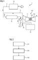
- FIG. 1 shows a schematic circuit view of an embodiment of the gas turbine-coupled storage system 1 according to the invention, which has a charging circuit 2 and a discharging circuit 3 in order to thermally charge or discharge a heat storage device 10.
- the charging circuit 2 has, in particular, a heat generating device 20 which is used in electrical operation, for example, can transfer heat to a working fluid which is not further provided with reference symbols in order to conduct this heat together with the working fluid to the heat accumulator 10.
- the heat generating device 20 is designed as a heat pump.
- Such a line preferably (not shown in the present case) has a heat supply line for low-temperature heat flows in order to use this for the thermal conditioning of the fluid for the compressor 101.
- thermodynamic efficiency improvement in particular during partial load operation.
- the present embodiment provides a bypass line 5 which allows fluid that is conveyed in the discharge circuit 3 to bypass the heat accumulator in order to subsequently transfer it with thermally conditioned fluid to mix before it is fed to the compressor 101 of the gas turbine 100.
- a suitable mixture can be achieved, for example, by two adjusting means 35 which are inserted into the discharge circuit 3 and which are suitably set with a control unit or regulating unit 30.
- the adjusting means 35 make it possible to influence the flow quantities which are supplied to the bypass line 5 or which are to be supplied to the heat accumulator 10 for heat exchange.
- the adjusting means 35 are particularly preferably dependent the partial load state of the gas turbine 100 is set. In this case, for example, increasingly warm fluid can be supplied to the compressor 101 as the partial load output of the gas turbine 100 decreases.
Landscapes
- Engineering & Computer Science (AREA)
- Chemical & Material Sciences (AREA)
- Combustion & Propulsion (AREA)
- Mechanical Engineering (AREA)
- General Engineering & Computer Science (AREA)
- Engine Equipment That Uses Special Cycles (AREA)
Description
- Die vorliegende Erfindung betrifft ein Gasturbinen gekoppeltes Speichersystem zur Speicherung von thermischer Energie in einem Wärmespeicher zur Vorwärmung eines an eine Ansaugseite einer Gasturbine geführten Fluids sowie ein Verfahren zum Betreiben eines solchen Speichersystems.
- Ein solches mit einer Gasturbine gekoppeltes Speichersystem ist etwa aus der
US 2011/0094236 A1 bekannt. Darin wird vorgeschlagen, bei vorhandenem Überschussstrom Verdichterluft in einer Kaverne zu speichern. Vor dem Speichervorgang in der Kaverne wird der Verdichterluft Wärme entzogen, um diese Wärme danach der Verdichterluft erneut zuzuführen, wenn diese aus der Kaverne entnommen und einer Brennkammer einer Gasturbine zugeführt wird. - Weiterhin ist in der
US 2010/0146981 A1 eine Verschaltung einer Gasturbine gelehrt, welche die Einsaugluft einer Gasturbine mit Hilfe eines Wärmetauschers thermisch zu höheren und zu niedrigeren Temperaturen konditionieren kann. Hierbei kann der Wärmetauscher mit thermisch konditioniertem Wasser beschickt werden, welches auch aus einem Kältetank zu Kühlzwecken entnommen werden kann. - Aufgrund des zunehmenden Anteils von elektrischer Energie aus fluktuierenden erneuerbaren Energiequellen in den öffentlichen Stromversorgungsnetzwerken werden Gaskraftwerke bzw. kombinierte Gas- und Dampfkraftwerke zunehmend nur als Reservekraftwerke bzw. zur Netzwerkstabilisierung benutzt. Diese Kraftwerke werden insbesondere zu Zeiten geringerer Energiebereitstellung durch die erneuerbaren Energiequellen betrieben, um die elektrische Energieversorgung sicherzustellen. Aufgrund dieser sich zunehmend verstärkenden Entwicklung werden diese Kraftwerke vermehrt in Teillast betrieben, also in einem Lastzustand, für welchen die Kraftwerke meistens nicht optimal ausgelegt sind. Aufgrund der nicht optimalen technischen Auslegung von Gasturbinen ist der auf den Brennstoff bezogene Wirkungsgrad im Teillastbetrieb geringer als bei Volllast.
- Wegen dieses Nachteils ist es wünschenswert, Gasturbinen hinsichtlich ihrer Flexibilität soweit zu verbessern, dass der Teillastwirkungsgrad bezogen auf den Brennstoffverbrauch erhöht wird. Eine solche Flexibilisierungsmaßnahme soll auch ermöglichen, die Gasturbine bei Bedarf über geringere Anfahrzeiten schneller anzufahren. Hierbei ist zu berücksichtigen, dass während des Anfahrbetriebs die Gasturbine ebenfalls über einen begrenzten Zeitraum in Teillast betrieben werden muss, bevor sie in dem hinsichtlich des Wirkungsgrades vorteilhaften Volllastzustand gefahren werden kann. Eine Teillastbetriebsverbesserung soll zudem aber, soweit wie möglich, energieeffizient vorgenommen werden, ohne hierbei ausschließlich wertvolle Primärenergie einzusetzen.
- Weiterhin stellt es sich als wünschenswert dar, bereits bestehende Gasturbinen durch einfache bauliche Änderungen für einen solchen, verbessert flexiblen Betrieb zu rüsten.
- Aufgabe der vorliegenden Erfindung ist es also, ein Gasturbinensystem vorzuschlagen, welches einen verbesserten Teillastbetrieb erlaubt.
- Erfindungsgemäß werden diese der Erfindung zugrunde liegenden Aufgaben durch eine Gasturbine mit einem gekoppelten Speichersystem gemäß Anspruch 1 sowie durch ein Verfahren zum Betrieb eines solchen Speichersystems gemäß Anspruch 6 gelöst.
- Insbesondere werden diese der Erfindung zugrundeliegenden Aufgaben gelöst durch ein Gasturbinen gekoppeltes Speichersystem zur Speicherung thermischer Energie in einem Wärmespeicher, mit einer Ladeschaltung und einer Entladeschaltung, wobei die Ladeschaltung mit einer elektrisch betriebenen Wärmeerzeugungseinrichtung versehen ist, die dazu ausgebildet ist, Wärme unter Nutzung von elektrischer Energie zu erzeugen, und wobei die Ladeschaltung dazu ausgebildet ist, diese Wärme wenigstens teilweise an den Wärmespeicher zu überführen, um sie darin zu speichern, und wobei die Entladeschaltung dazu ausgebildet ist, mittels der Wärme aus dem Wärmespeicher ein Fluid thermisch zu konditionieren, um dieses dann an die Ansaugseite eines Verdichters einer Gasturbine zu führen, und wobei die Ladeschaltung eine Wärmepumpe als Wärmeerzeugungseinrichtung aufweist.
- Weiter werden diese der Erfindung zugrundeliegenden Aufgaben gelöst durch ein Verfahren zum Betrieb eines solchen vorab, wie auch nachfolgend beschriebenen Speichersystems, welches folgende Schritte umfasst:
- Betreiben der Wärmeerzeugungseinrichtung zur Erzeugung von Wärme und Überführen dieser Wärme wenigstens teilweise mittels der Ladeschaltung an den Wärmespeicher;
- Zwischenspeichern der Wärme in dem Wärmespeicher;
- Überführen von mittels der Wärme aus dem Wärmespeicher thermisch konditioniertem Fluid an die Ansaugseite des Verdichters der Gasturbine.
- Erfindungsgemäß sieht das Gasturbinen gekoppelte Speichersystem somit einen Wärmespeicher vor, welcher mit Hilfe einer Ladeschaltung mit thermischer Energie geladen werden kann. Die thermische Energie stammt hierbei aus einer elektrisch betriebenen Wärmeerzeugungseinrichtung. Der elektrische Betrieb der Wärmeerzeugungseinrichtung erweist sich hierbei insofern als besonders vorteilhaft, da während des Ladens bzw. Entladens des Wärmespeichers keine Energie aus einem thermischen Kraftwerkskreislauf entnommen werden muss, wodurch beispielsweise in einem Kraftwerk der Energieerzeugungswirkungsgrad nachteilig beeinflusst werden könnte. Vielmehr erzeugt die Wärmeerzeugungseinrichtung thermische Energie durch Umsetzung von elektrischer Energie, welche anschließend mit Hilfe des Wärmespeichers zeitlich zwischengespeichert werden kann, um sie bei Bedarf zu einem späteren Zeitpunkt nutzen zu können. Hierbei erweist es sich als besonders vorteilhaft, insbesondere zu einem Zeitpunkt elektrische Energie in Wärme umzusetzen, wenn etwa solche im Übermaß etwa bei Vorherrschen von einem Überangebot an elektrischer Energie in den Stromversorgungsnetzwerken vorliegt.
- Die in dem Wärmespeicher zwischengespeicherte thermische Energie kann nun mittels der Entladeschaltung auf ein Fluid übertragen werden, welches anschließend an die Ansaugseite des Verdichters der Gasturbine geführt wird. Aufgrund dieser Vorwärmung des in den Verdichter der Gasturbine eingeführten Fluids kann infolge die Feuerungstemperatur in der Gasturbine erhöht werden, wodurch ebenfalls eine höhere Nutzenergieausbeute zu erwarten steht. So lässt beispielsweise die Entspannung von Abgas bei einer höheren Temperatur in der Expansionsturbine bei unverändertem Brennstoffverbrauch eine erhöhte Arbeitsleistung erwarten. Umgekehrt kann bei gleicher Leistung Brennstoff zur Verfeuerung in der Gasturbine eingespart werden. Wird zudem die thermische Energie des aus der Gasturbine nach der Verbrennung austretenden Abgases in einem weiteren thermischen Prozess genutzt, kann auch dieser bei höherem Wirkungsgrad betrieben werden. So kann beispielsweise der Betrieb eines mit der Gasturbine gekoppelten Dampfteils eines gekoppelten Gas- und Dampfkraftwerks bei erhöhtem Wirkungsgrad erfolgen.
- Erfindungsgemäß ist weiter vorgesehen, dass die Ladeschaltung eine Wärmepumpe als Wärmeerzeugungseinrichtung aufweist. Diese Wärmepumpe ist insbesondere dazu ausgebildet, dass sie mit einer Wärmezuleitung für Niedertemperaturwärmeströme versehen ist, um einen Wärmestrom, der im Niedertemperaturbereich liegt, hinsichtlich seines Wärmegehalts zu konditionieren. Derartige Niedertemperaturwärmeströme können bspw. aus Fernwärmenetzwerken bzw. aus Abwärmeleitungen einer Industrieanlage entnommen werden. Die Wärmepumpe erhöht hierbei durch zusätzliche Umsetzung von elektrischer Energie in thermische Energie den Wärmeinhalt des bereits vorhandenen Niedertemperaturwärmestroms signifikant. Derartige Wärmepumpen zeichnen sich typischerweise durch einen hohen COP-Wert (Coefficient of Performance) aus, der bei mindestens 1,5 liegt. Bei Betrieb einer solchen Wärmepumpe fällt eine energiebezogene Brennstoffeinsparung durch die Fluidvorwärmung höher aus, als es nur die elektrisch umgesetzte Energie ermöglichen könnte. In anderen Worten wird die Niedertemperaturwärme mittels der Wärmepumpe zusätzlich zur umgesetzten elektrischen Energie noch für die thermische Konditionierung des an die Gasturbine geführten Fluids vorteilhaft genutzt.
- Niedertemperaturwärme soll vorliegend all diejenigen Wärmequellen betreffen, die ein Temperaturniveau von nicht mehr als 150 °C aufweisen.
- An dieser Stelle sei darauf hingewiesen, dass das an die Ansaugseite des Verdichters der Gasturbine geführte Fluid bevorzugt als Luft ausgebildet ist. Dieses Fluid kann jedoch etwa aber auch als ein Abgas ausgebildet sein, welches zur Nachverbrennung vorgesehen sein kann. Weitere für eine Verbrennung in einer Gasturbine geeignete Stoffe, können ebenfalls mit von dem Fluid umfasst sein.
- Gemäß einer ersten besonders bevorzugten Ausführungsform der Erfindung ist vorgesehen, dass die Entladeschaltung dazu ausgebildet ist, das Fluid durch den Wärmespeicher zur thermischen Konditionierung zu führen. Alternativ oder auch zusätzlich kann die Ladeschaltung auch dazu ausgebildet sein, ein Arbeitsfluid, welches mit dem an die Gasturbine geführten Fluid identisch sein kann, durch den Wärmespeicher zur Wärmeentnahme zu führen. Das Arbeitsfluid könnte anschließend mit Hilfe eines geeigneten Wärmetauschers diese aufgenommene Wärme wenigstens zum Teil wieder an das Fluid, welches an die Gasturbine geführt wird, übertragen. Gemäß diesen Ausführungsformen erfolgt also der Wärmeübertrag zwischen dem Wärmespeicher und dem an die Gasturbine geführten Fluid direkt bzw. indirekt. Eine direkte Wärmeübertragung zeichnet sich durch einen hohen Wirkungsgrad aus, wohingegen eine indirekte Wärmeübertragung besonders verfahrenssicher und wartungsfreundlich ist.
- Gemäß einer weiteren besonders bevorzugten Ausführungsform der Erfindung ist vorgesehen, dass die Ladeschaltung eine Fluidwärmepumpe als Wärmeerzeugungseinrichtung aufweist, welche eine Verdichtereinheit sowie eine Expansionseinheit in fluidtechnischer Verschaltung miteinander aufweist. Insbesondere ist die Fluidwärmepumpe als Luftwärmepumpe ausgebildet, die gegenüber der Umgebung offen bzw. auch geschlossen ausgebildet sein kann. Bei offener Ausbildung kann Luft aus der Umgebung zur Verdichtereinheit geführt werden, wobei nach erfolgter Verdichtung und Expansion dieser Luft in der Expansionseinheit diese wiederum an die Umgebung zurück abgegeben werden kann. Zwischen Verdichtereinheit und Expansionseinheit ist zudem typischerweise noch ein Wärmetauscher geschaltet, welcher dazu ausgebildet ist, die bei der Kompression frei werdende Wärme gezielt abzuführen. Derartige Verdichtereinheiten wie auch Expansionseinheiten können bspw. von einer Gasturbine umfasst sein.
- Ausführungsgemäß erfordert der Betrieb der Fluidwärmepumpe ein Arbeitsfluid, welches zunächst mittels der Verdichtereinheit komprimiert wird, wobei gleichzeitig das Fluid adiabatisch erwärmt wird. Diese Wärme kann mittels des Wärmetauschers abgeführt und in dem Wärmespeicher zeitlich zwischengespeichert werden. Anschließend wird das so thermisch behandelte Arbeitsfluid mittels der Expansionseinheit wieder entspannt, wobei sich das Fluid erneut abkühlt.
- Die Fluidwärmepumpe kann bspw. von einer Gasturbine umfasst sein, welche zu Zeiten als Wärmepumpe betrieben wird, zu welchen kein elektrischer Strom erzeugt werden muss. Dabei kann die Verdichtereinheit sowie die Expansionseinheit von einem Generator angetrieben werden, der auch einen motorischen Betrieb erlaubt.
- Entsprechend eines weiteren besonders vorteilhaften Aspekts der Erfindung ist vorgesehen, dass die Entladeschaltung eine Umgehungsleitung aufweist, welche dazu ausgebildet ist, in die Entladeschaltung eingebrachtes Fluid unter Umgehung des Wärmespeichers der Ansaugseite des Verdichters der Gasturbine zuzuführen. Bevorzugt mündet diese Umgehungsleitung also in eine Zufuhrleitung, welche das Fluid, welches durch die Wärme des Wärmespeichers konditioniert wurde, an die Gasturbine führt, und so für eine Mischung von thermisch konditioniertem und nicht thermisch konditioniertem Fluid sorgt. Die Umgehungsleitung ermöglicht also eine verbesserte Temperierung des der Gasturbine zugeführten Fluids, wobei die Temperatur des Fluids dem entsprechenden Betriebszustand der Gasturbine angepasst werden kann. Insoweit kann bspw. je nach Lastzustand der Gasturbine, insbesondere je nach Teillastzustand der Gasturbine, Fluid eines erhöhten bzw. eines verminderten Temperaturniveaus, je nach Mischungsverhältnis zwischen thermisch konditioniertem und nicht thermisch konditioniertem Fluid, dem Verdichter zugeleitet werden. Durch diese Anpassung des Temperaturniveaus an den Lastzustand kann der Wirkungsgrad bei Betrieb der Gasturbine über verschiedene Teillastzustände gemittelt verbessert werden.
- Entsprechend einer weiteren bevorzugten Ausführungsform der Erfindung ist vorgesehen, dass die Ladeschaltung und die Entladeschaltung mit dem Wärmespeicher verschaltet sind, wobei der Wärmespeicher zwei Strömungskanäle, bevorzugt nur einen Strömungskanal aufweist. Die Strömungskanäle in dem Wärmespeicher können sowohl zur Wärmeaufnahme in den Wärmespeicher als auch zur Wärmeabgabe bei Entladung des Wärmespeichers dienen. In dem Fall, in welchem nur ein Strömungskanal in dem Wärmespeicher vorgesehen ist, kann der Wärmespeicher besonders kostengünstig und wartungsfreundlich gestaltet sein, da sowohl die Wärmeabgabe wie auch die Wärmeaufnahme in demselben Strömungskanal bzw. in den selben Strömungskanälen erfolgen kann.
- Entsprechend einer ersten besonders bevorzugten Ausführungsform des erfindungsgemäßen Verfahrens ist vorgesehen, dass der Schritt des Überführens von thermisch konditioniertem Fluid an die Ansaugseite des Verdichters der Gasturbine dann erfolgt, insbesondere nur dann erfolgt, wenn die Gasturbine in Teillast betrieben wird. Ein Teillastbetrieb liegt typischerweise dann vor, wenn ein Lastbereich von 30 bis 95 % der Nennleistung erreicht ist. Durch das Zuführen von thermischer Wärme während eines solchen Teillastbetriebes kann der Wirkungsgrad des Betriebs gesteigert werden, wodurch auch die daran gekoppelten thermodynamischen Prozesse, etwa zur Stromerzeugung, vorteilhaft beeinflusst werden.
- Gemäß einer Weiterführung dieser ausführungsgemäßen Idee ist vorgesehen, dass die Überführung von thermisch konditioniertem Fluid an die Ansaugseite des Verdichters derart gesteuert bzw. geregelt erfolgt, dass bei Verringerung der Teillastleistung der Gasturbine eine Erhöhung des Temperaturniveaus des thermisch konditionierten und an die Ansaugseite des Verdichters geleiteten Fluids eingestellt wird. Die Teillastleistung bezieht sich hierbei bevorzugt auf die elektrische Teillastleistung. Die Einstellung des Temperaturniveaus erfolgt folglich in Abhängigkeit der Teillastleistung der Gasturbine. Da sich bei veränderter Teillast auch der Wirkungsgrad des Betriebs verändert, kann durch eine geeignete Einstellung des Temperaturniveaus des an die Ansaugseite geleiteten Fluids eine angepasste Wirkungsgraderhöhung bei den verschiedenen Teillastzuständen vorgenommen werden. Insbesondere kann je nach Teillastzustand eine individuelle Einstellung des Temperaturniveaus erfolgen. Damit erhöht sich der Gesamtwirkungsgrad summiert über den Betrieb bei verschiedenen Teillastzuständen.
- Gemäß einer Weiterführung dieser ausführungsgemäßen Idee ist vorgesehen, dass die Steuerung bzw. Regelung des Temperaturniveaus durch ein Mischen von thermisch konditioniertem und nicht thermisch konditioniertem Fluid vor Zuführen der Mischung an die Ansaugseite der Gasturbine erfolgt, wobei insbesondere das nicht thermisch konditionierte Fluid über eine Umgehungsleitung zur Gasturbine geführt wird. Die Mischung von thermisch konditioniertem Fluid und nicht thermisch konditioniertem Fluid vor Zuführung der Mischung an die Gasturbine ist eine einfache Maßnahme um das Temperaturniveau des Gemisches geeignet einzustellen.
- Nachfolgend soll die Erfindung anhand einzelner Figuren im Detail näher erläutert werden. Hierbei sei darauf hingewiesen, dass die Figuren lediglich schematisch zu verstehen sind, wodurch keine Einschränkungen hinsichtlich der Ausführbarkeit der Erfindung bewirkt sein soll.
- Weiterhin sei darauf hingewiesen, dass die in den Figuren erwähnten Merkmale für sich alleine wie auch in beliebiger Kombination miteinander beansprucht werden sollen, soweit die erfindungsgemäße Kombination die der Erfindung zugrundeliegende Aufgabe lösen kann.
- Weiter ist darauf hinzuweisen, dass technische Merkmale, die mit gleichen Bezugszeichen versehen sind, gleiche technische Wirkungen aufweisen.
- Hierbei zeigen:
- Figur 1
- eine schematische Schaltansicht einer ersten Ausführungsform des erfindungsgemäßen Speichersystems 1;
- Figur 2
- eine Ausführungsform des erfindungsgemäßen Verfahrens zum Betrieb eines solchen Speichersystems 1 in flussdiagrammatischer Darstellung;
-
Figur 1 zeigt eine schematische Schaltansicht einer Ausführungsform des erfindungsgemäßen Gasturbinen gekoppelten Speichersystems 1, welches eine Ladeschaltung 2 sowie eine Entladeschaltung 3 aufweist, um einen Wärmespeicher 10 thermisch zu laden bzw. zu entladen. Die Ladeschaltung 2 weist insbesondere eine Wärmeerzeugungseinrichtung 20 auf, die bei elektrischem Betrieb etwa Wärme auf ein nicht weiter mit Bezugszeichen versehenes Arbeitsfluid übertragen kann, um diese Wärme zusammen mit dem Arbeitsfluid an den Wärmespeicher 10 zu führen. Bei thermischem Kontakt zwischen dem Arbeitsfluid und dem Wärmespeicher 10 kommt es zur Wärmeübertragung, wodurch der Wärmespeicher 10 thermisch aufgeladen werden kann. Erfindungsgemäß ist die Wärmeerzeugungseinrichtung 20 als Wärmepumpe ausgeführt. Eine solche hat vorzugsweise (vorliegend nicht gezeigt) eine Wärmezuleitung für Niedertemperaturwärmeströme, um diese bei der thermischen Konditionierung des Fluids für den Verdichter 101 zu nutzen. - Bei Entladen des Wärmespeichers 10 über die Entladeschaltung 3 wird ein ebenfalls nicht weiter mit Bezugszeichen versehenes Fluid an den Wärmespeicher 10 geleitet, um in diesem oder aus diesem thermische Energie aufnehmen zu können. Das so thermisch konditionierte thermische Fluid wird mittels der Entladeschaltung dem Verdichter 101 der Gasturbine 100 zugeführt. Durch die thermische Konditionierung kann insbesondere das Temperaturniveau während des Verbrennungsvorganges in der Brennkammer 102 erhöht werden, wodurch eine thermodynamische Wirkungsgradverbesserung insbesondere bei Teillastbetrieb resultiert.
- Um das Temperaturniveau des an den Verdichter 101 geführten Fluids geeignet einstellen zu können, sieht die vorliegende Ausführungsform eine Umgehungsleitung 5 vor, die es erlaubt, Fluid, welches in der Entladeschaltung 3 geführt wird, an dem Wärmespeicher vorbeizuführen, um es anschließend mit thermisch konditioniertem Fluid zu mischen, bevor es dem Verdichter 101 der Gasturbine 100 zugeführt wird. Eine geeignete Mischung kann etwa durch zwei in die Entladeschaltung 3 eingefügte Stellmittel 35 erreicht werden, die mit einer Steuerungseinheit bzw. Regelungseinheit 30 geeignet eingestellt werden. Die Stellmittel 35 ermöglichen, die Flussmengen zu beeinflussen, welche der Umgehungsleitung 5 zugeführt werden bzw. zum Wärmeaustausch dem Wärmespeicher 10 zugeführt werden sollen. Besonders bevorzugt werden die Stellmittel 35 in Abhängigkeit des Teillastzustands der Gasturbine 100 eingestellt. Hierbei kann etwa dem Verdichter 101 mit abnehmender Teillastleistung der Gasturbine 100 zunehmend warmes Fluid zugeführt werden.
-
Figur 2 zeigt eine flussdiagrammatische Darstellung einer Ausführungsform des erfindungsgemäßen Verfahrens zum Betrieb eines vorab beschriebenen Speichersystems 1, welches folgende Schritte umfasst: - Betreiben der Wärmeerzeugungseinrichtung (20) zur Erzeugung von Wärme und Überführen dieser Wärme wenigstens teilweise mittels der Ladeschaltung (2) an den Wärmespeicher (10) (erster Verfahrensschritt 201);
- Zwischenspeichern der Wärme in dem Wärmespeicher (10) (zweiter Verfahrensschritt 202);
- Überführen von mittels der Wärme aus dem Wärmespeicher (10) thermisch konditioniertem Fluid an die Ansaugseite des Verdichters (101) der Gasturbine (100) (dritter Verfahrensschritt 203);
- Weitere Ausführungsformen ergeben sich aus den Unteransprüchen.
Claims (9)
- Gasturbine mit einem gekoppelten Speichersystem (1) zur Speicherung thermischer Energie in einem Wärmespeicher (10), mit einer Ladeschaltung (2) und einer Entladeschaltung (3), wobei die Ladeschaltung (2) mit einer elektrisch betriebenen Wärmeerzeugungseinrichtung (20) versehen ist, die dazu ausgebildet ist, Wärme unter Nutzung von elektrischer Energie zu erzeugen, und wobei die Ladeschaltung (2) dazu ausgebildet ist, diese Wärme wenigstens teilweise an den Wärmespeicher (10) zu überführen, um sie darin zu speichern, und wobei die Entladeschaltung (3) dazu ausgebildet ist, mittels der Wärme aus dem Wärmespeicher (10) ein Fluid thermisch zu konditionieren, und um dieses dann an die Ansaugseite eines Verdichters (101) einer Gasturbine (100) zu führen,
dadurch gekennzeichnet, dass
die Ladeschaltung (2) eine Wärmepumpe als Wärmeerzeugungseinrichtung (20) aufweist. - Gasturbine mit einem gekoppelten Speichersystem (1) nach Anspruch 1,
dadurch gekennzeichnet, dass
die Wärmepumpe mit einer Wärmezuleitung für Niedertemperaturwärmeströme versehen ist, um einen Wärmestrom, der im Niedertemperaturbereich liegt, hinsichtlich seines Wärmegehalts zu konditionieren. - Gasturbine mit einem gekoppelten Speichersystem (1) nach Anspruch 1 oder 2,
dadurch gekennzeichnet, dass
die Entladeschaltung (3) dazu ausgebildet ist, das Fluid durch den Wärmespeicher (10) zur thermischen Konditionierung zu führen. - Gasturbine mit einem gekoppelten Speichersystem (1) nach einem der vorhergehenden Ansprüche,
dadurch gekennzeichnet, dass
die Entladeschaltung (3) eine Umgehungsleitung (5) aufweist, welche dazu ausgebildet ist, in die Entladeschaltung (3) eingebrachtes Fluid unter Umgehung des Wärmespeichers (10) der Ansaugseite des Verdichters (101) der Gasturbine (100) zuzuführen. - Gasturbine mit einem gekoppelten Speichersystem (1) nach einem der vorhergehenden Ansprüche,
dadurch gekennzeichnet, dass
die Ladeschaltung (2) und die Entladeschaltung (3) mit dem Wärmespeicher (10) verschaltet sind, wobei der Wärmespeicher (10) zwei Strömungskanäle, bevorzugt nur einen Strömungskanal aufweist. - Verfahren zum Betrieb einer Gasturbine mit einem gekoppelten Speichersystem (1), nach einem der vorhergehenden Ansprüche, welches folgende Schritte umfasst:- Betreiben der Wärmeerzeugungseinrichtung (20) zur Erzeugung von Wärme und Überführen dieser Wärme wenigstens teilweise mittels der Ladeschaltung (2) an den Wärmespeicher (10);- Zwischenspeichern der Wärme in dem Wärmespeicher (10);- Überführen von mittels der Wärme aus dem Wärmespeicher (10) thermisch konditioniertem Fluid an die Ansaugseite des Verdichters (101) der Gasturbine (100);
- Verfahren nach Anspruch 6,
dadurch gekennzeichnet, dass
der Schritt des Überführens von thermisch konditioniertem Fluid an die Ansaugseite des Verdichters (101) der Gasturbine (100) dann erfolgt, insbesondere nur dann erfolgt, wenn die Gasturbine (100) in Teillast betrieben wird. - Verfahren nach Anspruch 6 oder 7,
dadurch gekennzeichnet, dass
die Überführung von thermisch konditioniertem Fluid an die Ansaugseite des Verdichters (101) derart gesteuert bzw. geregelt erfolgt, dass bei Verringerung der Teillastleistung der Gasturbine (100) eine Erhöhung des Temperaturniveaus des thermisch konditionierten und an die Ansaugseite des Verdichters (101) geleiteten Fluids eingestellt wird. - Verfahren nach Anspruch 8,
dadurch gekennzeichnet, dass
die Steuerung bzw. Regelung des Temperaturniveaus durch ein Mischen von thermisch konditionierter und nicht thermisch konditioniertem Fluid vor Zuführen der Mischung an die Ansaugseite der Gasturbine (100) erfolgt, wobei insbesondere die nicht thermisch konditionierte Fluid über eine Umgehungsleitung (5) zur Gasturbine (100) geführt wird.
Applications Claiming Priority (2)
| Application Number | Priority Date | Filing Date | Title |
|---|---|---|---|
| DE102013210431.6A DE102013210431A1 (de) | 2013-06-05 | 2013-06-05 | Gasturbinen gekoppeltes Speichersystem zur Ansaugfluidvorwärmung |
| PCT/EP2014/059213 WO2014195075A1 (de) | 2013-06-05 | 2014-05-06 | Gasturbinen gekoppeltes speichersystem zur ansaugfluidvorwärmung |
Publications (2)
| Publication Number | Publication Date |
|---|---|
| EP2989310A1 EP2989310A1 (de) | 2016-03-02 |
| EP2989310B1 true EP2989310B1 (de) | 2021-03-31 |
Family
ID=50732137
Family Applications (1)
| Application Number | Title | Priority Date | Filing Date |
|---|---|---|---|
| EP14724378.6A Active EP2989310B1 (de) | 2013-06-05 | 2014-05-06 | Gasturbinen gekoppeltes speichersystem zur ansaugfluidvorwärmung |
Country Status (4)
| Country | Link |
|---|---|
| US (1) | US9897002B2 (de) |
| EP (1) | EP2989310B1 (de) |
| DE (1) | DE102013210431A1 (de) |
| WO (1) | WO2014195075A1 (de) |
Families Citing this family (1)
| Publication number | Priority date | Publication date | Assignee | Title |
|---|---|---|---|---|
| CZ307836B6 (cs) * | 2018-01-17 | 2019-06-12 | Vysoká Škola Báňská-Technická Univerzita Ostrava | Zařízení pro výrobu elektřiny s využitím akumulace médií |
Citations (1)
| Publication number | Priority date | Publication date | Assignee | Title |
|---|---|---|---|---|
| EP1577548A1 (de) * | 2004-03-16 | 2005-09-21 | Abb Research Ltd. | Vorrichtung und Verfahren zur Speicherung thermischer Energie und Erzeugung von Elektrizität |
Family Cites Families (10)
| Publication number | Priority date | Publication date | Assignee | Title |
|---|---|---|---|---|
| DE19531562A1 (de) * | 1995-08-28 | 1997-03-06 | Abb Management Ag | Verfahren zum Betrieb einer Kraftwerksanlage |
| JP3358460B2 (ja) * | 1996-09-20 | 2002-12-16 | 株式会社日立製作所 | 化学蓄熱式吸気冷却装置 |
| US6513318B1 (en) * | 2000-11-29 | 2003-02-04 | Hybrid Power Generation Systems Llc | Low emissions gas turbine engine with inlet air heating |
| DE102004050182B4 (de) * | 2004-10-14 | 2009-10-22 | Triesch, Frank, Dr. Ing. | Verfahren zur Luftkonditionierung |
| WO2007134466A1 (en) * | 2006-05-24 | 2007-11-29 | Abb Research Ltd | Thermoelectric energy storage system and method for storing thermoelectric energy |
| US9470149B2 (en) * | 2008-12-11 | 2016-10-18 | General Electric Company | Turbine inlet air heat pump-type system |
| US8468830B2 (en) * | 2008-12-11 | 2013-06-25 | General Electric Company | Inlet air heating and cooling system |
| US8341964B2 (en) * | 2009-10-27 | 2013-01-01 | General Electric Company | System and method of using a compressed air storage system with a gas turbine |
| EP2574865A1 (de) | 2011-09-29 | 2013-04-03 | Siemens Aktiengesellschaft | Energiespeichervorrichtung sowie Verfahren zur Speicherung von Energie |
| WO2013116185A1 (en) * | 2012-01-30 | 2013-08-08 | Kraft Robert J | Gas turbine energy storage and energy supplementing systems and methods of making and using the same |
-
2013
- 2013-06-05 DE DE102013210431.6A patent/DE102013210431A1/de not_active Withdrawn
-
2014
- 2014-05-06 EP EP14724378.6A patent/EP2989310B1/de active Active
- 2014-05-06 US US14/895,043 patent/US9897002B2/en active Active
- 2014-05-06 WO PCT/EP2014/059213 patent/WO2014195075A1/de not_active Ceased
Patent Citations (1)
| Publication number | Priority date | Publication date | Assignee | Title |
|---|---|---|---|---|
| EP1577548A1 (de) * | 2004-03-16 | 2005-09-21 | Abb Research Ltd. | Vorrichtung und Verfahren zur Speicherung thermischer Energie und Erzeugung von Elektrizität |
Also Published As
| Publication number | Publication date |
|---|---|
| US20160341121A1 (en) | 2016-11-24 |
| US9897002B2 (en) | 2018-02-20 |
| WO2014195075A1 (de) | 2014-12-11 |
| EP2989310A1 (de) | 2016-03-02 |
| DE102013210431A1 (de) | 2014-12-24 |
Similar Documents
| Publication | Publication Date | Title |
|---|---|---|
| EP2865045B1 (de) | Kraftwerksanordnung mit hochtemperatur-speichereinheit | |
| EP3138148B1 (de) | Kraft-wärme-kopplungsanlage zur dezentralen strom- und wärmeversorgung | |
| DE102014105237B3 (de) | Verfahren und Vorrichtung zum Speichern und Rückgewinnen von Energie | |
| DE102010027302B4 (de) | Energiespeichersystem | |
| DE102010042792A1 (de) | System zur Erzeugung mechanischer und/oder elektrischer Energie | |
| WO2005019606A1 (de) | Verfahren zur erhöhung des wirkungsgrades einer gasturbinenanlage sowie dafür geeignete gasturbinenanlage | |
| EP2594746A1 (de) | Gasturbinenkraftwerk mit einer Gasturbinenanlage und Verfahren zum Betreiben eines Gasturbinenkraftwerks | |
| DE4410440A1 (de) | Druckluftenergiespeicherverfahren und -system | |
| DE102018201172A1 (de) | Verbrennungsanlage mit Restwärmenutzung | |
| WO2004001288A1 (de) | Abhitzedampferzeuger | |
| EP2196633A1 (de) | Kraftwerk mit einer Turbineneinheit und einem Generator | |
| EP2288791B1 (de) | Betrieb einer gas- und dampfturbinenanlage mittels frequenzumrichter | |
| EP2802757B1 (de) | Gaskraftwerk | |
| EP2876280B1 (de) | Mikrogasturbinenanordnung | |
| DE19652349A1 (de) | Solar- und Niedertemperaturwärme-Kombianlage-Solico | |
| DE102013206992A1 (de) | Bereitstellung negativer Regelleistung durch eine Gasturbine | |
| DE102013210431A1 (de) | Gasturbinen gekoppeltes Speichersystem zur Ansaugfluidvorwärmung | |
| EP2708719A1 (de) | Erweitertes Gaskraftwerk zur Stromspeicherung | |
| EP2674592A1 (de) | Gasturbinenprozess mit Aufwindkraftwerk | |
| EP2982835A1 (de) | Wärmekraftwerk mit einer dampfturbine | |
| EP2932054A2 (de) | Gasturbinenkraftwerk mit verbesserter flexibilisierung | |
| DE102012223818A1 (de) | Einsatz eines Hilfsaggregates zur Bereitstellung von Abgaswärme für den Abhitzedampferzeuger eines GuD-Kraftwerks | |
| DE102014119686A1 (de) | Druckspeicherkraftwerk mit kombiniertem, rekuperativem Abhitzedampferzeuger | |
| EP2999869A1 (de) | Flexibilisiertes gasturbinenkraftwerk | |
| WO2024260652A1 (de) | Druckluftspeicherkraftwerk und verfahren zum betreiben eines solchen druckluftspeicherkraftwerks |
Legal Events
| Date | Code | Title | Description |
|---|---|---|---|
| PUAI | Public reference made under article 153(3) epc to a published international application that has entered the european phase |
Free format text: ORIGINAL CODE: 0009012 |
|
| 17P | Request for examination filed |
Effective date: 20151123 |
|
| AK | Designated contracting states |
Kind code of ref document: A1 Designated state(s): AL AT BE BG CH CY CZ DE DK EE ES FI FR GB GR HR HU IE IS IT LI LT LU LV MC MK MT NL NO PL PT RO RS SE SI SK SM TR |
|
| AX | Request for extension of the european patent |
Extension state: BA ME |
|
| DAX | Request for extension of the european patent (deleted) | ||
| STAA | Information on the status of an ep patent application or granted ep patent |
Free format text: STATUS: EXAMINATION IS IN PROGRESS |
|
| RAP1 | Party data changed (applicant data changed or rights of an application transferred) |
Owner name: SIEMENS AKTIENGESELLSCHAFT |
|
| 17Q | First examination report despatched |
Effective date: 20170825 |
|
| GRAP | Despatch of communication of intention to grant a patent |
Free format text: ORIGINAL CODE: EPIDOSNIGR1 |
|
| STAA | Information on the status of an ep patent application or granted ep patent |
Free format text: STATUS: GRANT OF PATENT IS INTENDED |
|
| INTG | Intention to grant announced |
Effective date: 20201202 |
|
| RAP1 | Party data changed (applicant data changed or rights of an application transferred) |
Owner name: SIEMENS ENERGY GLOBAL GMBH & CO. KG |
|
| GRAS | Grant fee paid |
Free format text: ORIGINAL CODE: EPIDOSNIGR3 |
|
| GRAA | (expected) grant |
Free format text: ORIGINAL CODE: 0009210 |
|
| STAA | Information on the status of an ep patent application or granted ep patent |
Free format text: STATUS: THE PATENT HAS BEEN GRANTED |
|
| AK | Designated contracting states |
Kind code of ref document: B1 Designated state(s): AL AT BE BG CH CY CZ DE DK EE ES FI FR GB GR HR HU IE IS IT LI LT LU LV MC MK MT NL NO PL PT RO RS SE SI SK SM TR |
|
| REG | Reference to a national code |
Ref country code: GB Ref legal event code: FG4D Free format text: NOT ENGLISH Ref country code: CH Ref legal event code: EP |
|
| REG | Reference to a national code |
Ref country code: DE Ref legal event code: R096 Ref document number: 502014015433 Country of ref document: DE Ref country code: AT Ref legal event code: REF Ref document number: 1377186 Country of ref document: AT Kind code of ref document: T Effective date: 20210415 |
|
| REG | Reference to a national code |
Ref country code: IE Ref legal event code: FG4D Free format text: LANGUAGE OF EP DOCUMENT: GERMAN |
|
| REG | Reference to a national code |
Ref country code: LT Ref legal event code: MG9D |
|
| PG25 | Lapsed in a contracting state [announced via postgrant information from national office to epo] |
Ref country code: NO Free format text: LAPSE BECAUSE OF FAILURE TO SUBMIT A TRANSLATION OF THE DESCRIPTION OR TO PAY THE FEE WITHIN THE PRESCRIBED TIME-LIMIT Effective date: 20210630 Ref country code: BG Free format text: LAPSE BECAUSE OF FAILURE TO SUBMIT A TRANSLATION OF THE DESCRIPTION OR TO PAY THE FEE WITHIN THE PRESCRIBED TIME-LIMIT Effective date: 20210630 Ref country code: FI Free format text: LAPSE BECAUSE OF FAILURE TO SUBMIT A TRANSLATION OF THE DESCRIPTION OR TO PAY THE FEE WITHIN THE PRESCRIBED TIME-LIMIT Effective date: 20210331 Ref country code: HR Free format text: LAPSE BECAUSE OF FAILURE TO SUBMIT A TRANSLATION OF THE DESCRIPTION OR TO PAY THE FEE WITHIN THE PRESCRIBED TIME-LIMIT Effective date: 20210331 |
|
| PG25 | Lapsed in a contracting state [announced via postgrant information from national office to epo] |
Ref country code: SE Free format text: LAPSE BECAUSE OF FAILURE TO SUBMIT A TRANSLATION OF THE DESCRIPTION OR TO PAY THE FEE WITHIN THE PRESCRIBED TIME-LIMIT Effective date: 20210331 Ref country code: LV Free format text: LAPSE BECAUSE OF FAILURE TO SUBMIT A TRANSLATION OF THE DESCRIPTION OR TO PAY THE FEE WITHIN THE PRESCRIBED TIME-LIMIT Effective date: 20210331 Ref country code: RS Free format text: LAPSE BECAUSE OF FAILURE TO SUBMIT A TRANSLATION OF THE DESCRIPTION OR TO PAY THE FEE WITHIN THE PRESCRIBED TIME-LIMIT Effective date: 20210331 |
|
| REG | Reference to a national code |
Ref country code: NL Ref legal event code: MP Effective date: 20210331 |
|
| PG25 | Lapsed in a contracting state [announced via postgrant information from national office to epo] |
Ref country code: CZ Free format text: LAPSE BECAUSE OF FAILURE TO SUBMIT A TRANSLATION OF THE DESCRIPTION OR TO PAY THE FEE WITHIN THE PRESCRIBED TIME-LIMIT Effective date: 20210331 Ref country code: EE Free format text: LAPSE BECAUSE OF FAILURE TO SUBMIT A TRANSLATION OF THE DESCRIPTION OR TO PAY THE FEE WITHIN THE PRESCRIBED TIME-LIMIT Effective date: 20210331 Ref country code: NL Free format text: LAPSE BECAUSE OF FAILURE TO SUBMIT A TRANSLATION OF THE DESCRIPTION OR TO PAY THE FEE WITHIN THE PRESCRIBED TIME-LIMIT Effective date: 20210331 Ref country code: LT Free format text: LAPSE BECAUSE OF FAILURE TO SUBMIT A TRANSLATION OF THE DESCRIPTION OR TO PAY THE FEE WITHIN THE PRESCRIBED TIME-LIMIT Effective date: 20210331 Ref country code: SM Free format text: LAPSE BECAUSE OF FAILURE TO SUBMIT A TRANSLATION OF THE DESCRIPTION OR TO PAY THE FEE WITHIN THE PRESCRIBED TIME-LIMIT Effective date: 20210331 |
|
| PG25 | Lapsed in a contracting state [announced via postgrant information from national office to epo] |
Ref country code: IS Free format text: LAPSE BECAUSE OF FAILURE TO SUBMIT A TRANSLATION OF THE DESCRIPTION OR TO PAY THE FEE WITHIN THE PRESCRIBED TIME-LIMIT Effective date: 20210731 Ref country code: ES Free format text: LAPSE BECAUSE OF FAILURE TO SUBMIT A TRANSLATION OF THE DESCRIPTION OR TO PAY THE FEE WITHIN THE PRESCRIBED TIME-LIMIT Effective date: 20210331 Ref country code: PT Free format text: LAPSE BECAUSE OF FAILURE TO SUBMIT A TRANSLATION OF THE DESCRIPTION OR TO PAY THE FEE WITHIN THE PRESCRIBED TIME-LIMIT Effective date: 20210802 Ref country code: PL Free format text: LAPSE BECAUSE OF FAILURE TO SUBMIT A TRANSLATION OF THE DESCRIPTION OR TO PAY THE FEE WITHIN THE PRESCRIBED TIME-LIMIT Effective date: 20210331 Ref country code: SK Free format text: LAPSE BECAUSE OF FAILURE TO SUBMIT A TRANSLATION OF THE DESCRIPTION OR TO PAY THE FEE WITHIN THE PRESCRIBED TIME-LIMIT Effective date: 20210331 Ref country code: RO Free format text: LAPSE BECAUSE OF FAILURE TO SUBMIT A TRANSLATION OF THE DESCRIPTION OR TO PAY THE FEE WITHIN THE PRESCRIBED TIME-LIMIT Effective date: 20210331 |
|
| REG | Reference to a national code |
Ref country code: CH Ref legal event code: PL |
|
| REG | Reference to a national code |
Ref country code: DE Ref legal event code: R097 Ref document number: 502014015433 Country of ref document: DE |
|
| PG25 | Lapsed in a contracting state [announced via postgrant information from national office to epo] |
Ref country code: MC Free format text: LAPSE BECAUSE OF FAILURE TO SUBMIT A TRANSLATION OF THE DESCRIPTION OR TO PAY THE FEE WITHIN THE PRESCRIBED TIME-LIMIT Effective date: 20210331 Ref country code: LI Free format text: LAPSE BECAUSE OF NON-PAYMENT OF DUE FEES Effective date: 20210531 Ref country code: LU Free format text: LAPSE BECAUSE OF NON-PAYMENT OF DUE FEES Effective date: 20210506 Ref country code: AL Free format text: LAPSE BECAUSE OF FAILURE TO SUBMIT A TRANSLATION OF THE DESCRIPTION OR TO PAY THE FEE WITHIN THE PRESCRIBED TIME-LIMIT Effective date: 20210331 Ref country code: CH Free format text: LAPSE BECAUSE OF NON-PAYMENT OF DUE FEES Effective date: 20210531 Ref country code: DK Free format text: LAPSE BECAUSE OF FAILURE TO SUBMIT A TRANSLATION OF THE DESCRIPTION OR TO PAY THE FEE WITHIN THE PRESCRIBED TIME-LIMIT Effective date: 20210331 |
|
| PLBE | No opposition filed within time limit |
Free format text: ORIGINAL CODE: 0009261 |
|
| STAA | Information on the status of an ep patent application or granted ep patent |
Free format text: STATUS: NO OPPOSITION FILED WITHIN TIME LIMIT |
|
| REG | Reference to a national code |
Ref country code: BE Ref legal event code: MM Effective date: 20210531 |
|
| 26N | No opposition filed |
Effective date: 20220104 |
|
| PG25 | Lapsed in a contracting state [announced via postgrant information from national office to epo] |
Ref country code: IE Free format text: LAPSE BECAUSE OF NON-PAYMENT OF DUE FEES Effective date: 20210506 |
|
| PG25 | Lapsed in a contracting state [announced via postgrant information from national office to epo] |
Ref country code: IS Free format text: LAPSE BECAUSE OF FAILURE TO SUBMIT A TRANSLATION OF THE DESCRIPTION OR TO PAY THE FEE WITHIN THE PRESCRIBED TIME-LIMIT Effective date: 20210731 Ref country code: FR Free format text: LAPSE BECAUSE OF NON-PAYMENT OF DUE FEES Effective date: 20210531 |
|
| PG25 | Lapsed in a contracting state [announced via postgrant information from national office to epo] |
Ref country code: IT Free format text: LAPSE BECAUSE OF FAILURE TO SUBMIT A TRANSLATION OF THE DESCRIPTION OR TO PAY THE FEE WITHIN THE PRESCRIBED TIME-LIMIT Effective date: 20210331 Ref country code: BE Free format text: LAPSE BECAUSE OF NON-PAYMENT OF DUE FEES Effective date: 20210531 |
|
| PG25 | Lapsed in a contracting state [announced via postgrant information from national office to epo] |
Ref country code: HU Free format text: LAPSE BECAUSE OF FAILURE TO SUBMIT A TRANSLATION OF THE DESCRIPTION OR TO PAY THE FEE WITHIN THE PRESCRIBED TIME-LIMIT; INVALID AB INITIO Effective date: 20140506 |
|
| PG25 | Lapsed in a contracting state [announced via postgrant information from national office to epo] |
Ref country code: CY Free format text: LAPSE BECAUSE OF FAILURE TO SUBMIT A TRANSLATION OF THE DESCRIPTION OR TO PAY THE FEE WITHIN THE PRESCRIBED TIME-LIMIT Effective date: 20210331 |
|
| PG25 | Lapsed in a contracting state [announced via postgrant information from national office to epo] |
Ref country code: GR Free format text: LAPSE BECAUSE OF FAILURE TO SUBMIT A TRANSLATION OF THE DESCRIPTION OR TO PAY THE FEE WITHIN THE PRESCRIBED TIME-LIMIT Effective date: 20210331 |
|
| PGFP | Annual fee paid to national office [announced via postgrant information from national office to epo] |
Ref country code: AT Payment date: 20230519 Year of fee payment: 10 |
|
| PGFP | Annual fee paid to national office [announced via postgrant information from national office to epo] |
Ref country code: GB Payment date: 20230523 Year of fee payment: 10 |
|
| PG25 | Lapsed in a contracting state [announced via postgrant information from national office to epo] |
Ref country code: MK Free format text: LAPSE BECAUSE OF FAILURE TO SUBMIT A TRANSLATION OF THE DESCRIPTION OR TO PAY THE FEE WITHIN THE PRESCRIBED TIME-LIMIT Effective date: 20210331 |
|
| PG25 | Lapsed in a contracting state [announced via postgrant information from national office to epo] |
Ref country code: MT Free format text: LAPSE BECAUSE OF FAILURE TO SUBMIT A TRANSLATION OF THE DESCRIPTION OR TO PAY THE FEE WITHIN THE PRESCRIBED TIME-LIMIT Effective date: 20210331 |
|
| REG | Reference to a national code |
Ref country code: AT Ref legal event code: MM01 Ref document number: 1377186 Country of ref document: AT Kind code of ref document: T Effective date: 20240506 |
|
| PG25 | Lapsed in a contracting state [announced via postgrant information from national office to epo] |
Ref country code: AT Free format text: LAPSE BECAUSE OF NON-PAYMENT OF DUE FEES Effective date: 20240506 |
|
| GBPC | Gb: european patent ceased through non-payment of renewal fee |
Effective date: 20240506 |
|
| PG25 | Lapsed in a contracting state [announced via postgrant information from national office to epo] |
Ref country code: AT Free format text: LAPSE BECAUSE OF NON-PAYMENT OF DUE FEES Effective date: 20240506 |
|
| PG25 | Lapsed in a contracting state [announced via postgrant information from national office to epo] |
Ref country code: GB Free format text: LAPSE BECAUSE OF NON-PAYMENT OF DUE FEES Effective date: 20240506 |
|
| PGFP | Annual fee paid to national office [announced via postgrant information from national office to epo] |
Ref country code: DE Payment date: 20250528 Year of fee payment: 12 |
|
| PG25 | Lapsed in a contracting state [announced via postgrant information from national office to epo] |
Ref country code: TR Free format text: LAPSE BECAUSE OF FAILURE TO SUBMIT A TRANSLATION OF THE DESCRIPTION OR TO PAY THE FEE WITHIN THE PRESCRIBED TIME-LIMIT Effective date: 20210331 |