EP2989304B1 - Smart heating system - Google Patents
Smart heating system Download PDFInfo
- Publication number
- EP2989304B1 EP2989304B1 EP14729132.2A EP14729132A EP2989304B1 EP 2989304 B1 EP2989304 B1 EP 2989304B1 EP 14729132 A EP14729132 A EP 14729132A EP 2989304 B1 EP2989304 B1 EP 2989304B1
- Authority
- EP
- European Patent Office
- Prior art keywords
- heater
- heating system
- smart heating
- temperature
- information
- Prior art date
- Legal status (The legal status is an assumption and is not a legal conclusion. Google has not performed a legal analysis and makes no representation as to the accuracy of the status listed.)
- Active
Links
Images





Classifications
-
- G—PHYSICS
- G05—CONTROLLING; REGULATING
- G05D—SYSTEMS FOR CONTROLLING OR REGULATING NON-ELECTRIC VARIABLES
- G05D23/00—Control of temperature
- G05D23/19—Control of temperature characterised by the use of electric means
-
- F—MECHANICAL ENGINEERING; LIGHTING; HEATING; WEAPONS; BLASTING
- F01—MACHINES OR ENGINES IN GENERAL; ENGINE PLANTS IN GENERAL; STEAM ENGINES
- F01N—GAS-FLOW SILENCERS OR EXHAUST APPARATUS FOR MACHINES OR ENGINES IN GENERAL; GAS-FLOW SILENCERS OR EXHAUST APPARATUS FOR INTERNAL-COMBUSTION ENGINES
- F01N3/00—Exhaust or silencing apparatus having means for purifying, rendering innocuous, or otherwise treating exhaust
- F01N3/02—Exhaust or silencing apparatus having means for purifying, rendering innocuous, or otherwise treating exhaust for cooling, or for removing solid constituents of, exhaust
- F01N3/021—Exhaust or silencing apparatus having means for purifying, rendering innocuous, or otherwise treating exhaust for cooling, or for removing solid constituents of, exhaust by means of filters
- F01N3/023—Exhaust or silencing apparatus having means for purifying, rendering innocuous, or otherwise treating exhaust for cooling, or for removing solid constituents of, exhaust by means of filters using means for regenerating the filters, e.g. by burning trapped particles
- F01N3/027—Exhaust or silencing apparatus having means for purifying, rendering innocuous, or otherwise treating exhaust for cooling, or for removing solid constituents of, exhaust by means of filters using means for regenerating the filters, e.g. by burning trapped particles using electric or magnetic heating means
-
- F—MECHANICAL ENGINEERING; LIGHTING; HEATING; WEAPONS; BLASTING
- F01—MACHINES OR ENGINES IN GENERAL; ENGINE PLANTS IN GENERAL; STEAM ENGINES
- F01N—GAS-FLOW SILENCERS OR EXHAUST APPARATUS FOR MACHINES OR ENGINES IN GENERAL; GAS-FLOW SILENCERS OR EXHAUST APPARATUS FOR INTERNAL-COMBUSTION ENGINES
- F01N3/00—Exhaust or silencing apparatus having means for purifying, rendering innocuous, or otherwise treating exhaust
- F01N3/08—Exhaust or silencing apparatus having means for purifying, rendering innocuous, or otherwise treating exhaust for rendering innocuous
- F01N3/10—Exhaust or silencing apparatus having means for purifying, rendering innocuous, or otherwise treating exhaust for rendering innocuous by thermal or catalytic conversion of noxious components of exhaust
- F01N3/18—Exhaust or silencing apparatus having means for purifying, rendering innocuous, or otherwise treating exhaust for rendering innocuous by thermal or catalytic conversion of noxious components of exhaust characterised by methods of operation; Control
- F01N3/20—Exhaust or silencing apparatus having means for purifying, rendering innocuous, or otherwise treating exhaust for rendering innocuous by thermal or catalytic conversion of noxious components of exhaust characterised by methods of operation; Control specially adapted for catalytic conversion
- F01N3/2006—Periodically heating or cooling catalytic reactors, e.g. at cold starting or overheating
- F01N3/2013—Periodically heating or cooling catalytic reactors, e.g. at cold starting or overheating using electric or magnetic heating means
-
- G—PHYSICS
- G05—CONTROLLING; REGULATING
- G05B—CONTROL OR REGULATING SYSTEMS IN GENERAL; FUNCTIONAL ELEMENTS OF SUCH SYSTEMS; MONITORING OR TESTING ARRANGEMENTS FOR SUCH SYSTEMS OR ELEMENTS
- G05B15/00—Systems controlled by a computer
- G05B15/02—Systems controlled by a computer electric
-
- H—ELECTRICITY
- H05—ELECTRIC TECHNIQUES NOT OTHERWISE PROVIDED FOR
- H05B—ELECTRIC HEATING; ELECTRIC LIGHT SOURCES NOT OTHERWISE PROVIDED FOR; CIRCUIT ARRANGEMENTS FOR ELECTRIC LIGHT SOURCES, IN GENERAL
- H05B1/00—Details of electric heating devices
- H05B1/02—Automatic switching arrangements specially adapted to apparatus ; Control of heating devices
- H05B1/0227—Applications
- H05B1/023—Industrial applications
- H05B1/0236—Industrial applications for vehicles
-
- F—MECHANICAL ENGINEERING; LIGHTING; HEATING; WEAPONS; BLASTING
- F01—MACHINES OR ENGINES IN GENERAL; ENGINE PLANTS IN GENERAL; STEAM ENGINES
- F01N—GAS-FLOW SILENCERS OR EXHAUST APPARATUS FOR MACHINES OR ENGINES IN GENERAL; GAS-FLOW SILENCERS OR EXHAUST APPARATUS FOR INTERNAL-COMBUSTION ENGINES
- F01N2240/00—Combination or association of two or more different exhaust treating devices, or of at least one such device with an auxiliary device, not covered by indexing codes F01N2230/00 or F01N2250/00, one of the devices being
- F01N2240/16—Combination or association of two or more different exhaust treating devices, or of at least one such device with an auxiliary device, not covered by indexing codes F01N2230/00 or F01N2250/00, one of the devices being an electric heater, i.e. a resistance heater
-
- F—MECHANICAL ENGINEERING; LIGHTING; HEATING; WEAPONS; BLASTING
- F01—MACHINES OR ENGINES IN GENERAL; ENGINE PLANTS IN GENERAL; STEAM ENGINES
- F01N—GAS-FLOW SILENCERS OR EXHAUST APPARATUS FOR MACHINES OR ENGINES IN GENERAL; GAS-FLOW SILENCERS OR EXHAUST APPARATUS FOR INTERNAL-COMBUSTION ENGINES
- F01N2550/00—Monitoring or diagnosing the deterioration of exhaust systems
- F01N2550/22—Monitoring or diagnosing the deterioration of exhaust systems of electric heaters for exhaust systems or their power supply
-
- F—MECHANICAL ENGINEERING; LIGHTING; HEATING; WEAPONS; BLASTING
- F01—MACHINES OR ENGINES IN GENERAL; ENGINE PLANTS IN GENERAL; STEAM ENGINES
- F01N—GAS-FLOW SILENCERS OR EXHAUST APPARATUS FOR MACHINES OR ENGINES IN GENERAL; GAS-FLOW SILENCERS OR EXHAUST APPARATUS FOR INTERNAL-COMBUSTION ENGINES
- F01N2560/00—Exhaust systems with means for detecting or measuring exhaust gas components or characteristics
- F01N2560/06—Exhaust systems with means for detecting or measuring exhaust gas components or characteristics the means being a temperature sensor
-
- F—MECHANICAL ENGINEERING; LIGHTING; HEATING; WEAPONS; BLASTING
- F01—MACHINES OR ENGINES IN GENERAL; ENGINE PLANTS IN GENERAL; STEAM ENGINES
- F01N—GAS-FLOW SILENCERS OR EXHAUST APPARATUS FOR MACHINES OR ENGINES IN GENERAL; GAS-FLOW SILENCERS OR EXHAUST APPARATUS FOR INTERNAL-COMBUSTION ENGINES
- F01N2900/00—Details of electrical control or of the monitoring of the exhaust gas treating apparatus
- F01N2900/04—Methods of control or diagnosing
- F01N2900/0408—Methods of control or diagnosing using a feed-back loop
-
- F—MECHANICAL ENGINEERING; LIGHTING; HEATING; WEAPONS; BLASTING
- F01—MACHINES OR ENGINES IN GENERAL; ENGINE PLANTS IN GENERAL; STEAM ENGINES
- F01N—GAS-FLOW SILENCERS OR EXHAUST APPARATUS FOR MACHINES OR ENGINES IN GENERAL; GAS-FLOW SILENCERS OR EXHAUST APPARATUS FOR INTERNAL-COMBUSTION ENGINES
- F01N2900/00—Details of electrical control or of the monitoring of the exhaust gas treating apparatus
- F01N2900/06—Parameters used for exhaust control or diagnosing
- F01N2900/16—Parameters used for exhaust control or diagnosing said parameters being related to the exhaust apparatus, e.g. particulate filter or catalyst
- F01N2900/1602—Temperature of exhaust gas apparatus
-
- Y—GENERAL TAGGING OF NEW TECHNOLOGICAL DEVELOPMENTS; GENERAL TAGGING OF CROSS-SECTIONAL TECHNOLOGIES SPANNING OVER SEVERAL SECTIONS OF THE IPC; TECHNICAL SUBJECTS COVERED BY FORMER USPC CROSS-REFERENCE ART COLLECTIONS [XRACs] AND DIGESTS
- Y02—TECHNOLOGIES OR APPLICATIONS FOR MITIGATION OR ADAPTATION AGAINST CLIMATE CHANGE
- Y02T—CLIMATE CHANGE MITIGATION TECHNOLOGIES RELATED TO TRANSPORTATION
- Y02T10/00—Road transport of goods or passengers
- Y02T10/10—Internal combustion engine [ICE] based vehicles
- Y02T10/12—Improving ICE efficiencies
Definitions
- This disclosure relates generally to temperature management. More specifically, this disclosure relates to systems and methods for measuring and compensating for heat transfer differences and other environmental heat transfer related aspects of thermal systems.
- Heat flux is a useful measure for predicting relative heater element performance, including temperature, transfer efficiency, and life-time.
- the flux density exhibited by a heater element is defined as Watt density (watts/mm 2 ), which represents a measure of the magnitude of the power that can be concentrated per square millimeter of an element's surface area.
- a heater element that exhibits a high Watt density will generally provide a fast temperature rise and a lower overall manufacturing cost due to the reduced amount of surface area that is required.
- these advantages are often off-set by the risk of reduced lifetime due to the higher surface temperatures that are encountered, as well as the potential for lower reliability (e.g., over-shooting the desired temperature condition, etc.).
- US 2008/028753 A1 discloses a heater system according to the preamble of claim 1.
- the present invention provides a smart heating system according to claim 1.
- the performance information may be stored as written text, a bar code, a data matrix, or a radio frequency identification (RFID) tag.
- the smart heating system heating system may further comprises a LIN or a CAN bus capable of providing a communication pathway between at least two system components.
- the smart heating system may further comprise at least one support bracket in contact with the at least one heater element and optionally with the at least one temperature sensor.
- the performance information may include only heater information or a combination of both heater and sensor information.
- the heater performance information may include the rate of heating that occurs at a desired voltage or under a specified flow condition.
- the heating system may further comprise a power switch that receives signals from the ECU.
- the performance information may also include switch information.
- the power switch can be controlled by a switch control unit that is in communication with the ECU and uses the switch information.
- the switch information may include a measurement of the current and/or voltage, as well as the rate of heating associated with the solid state components of the switch as a function of the amount of electrical current that is being switched.
- the smart heating system includes multiple heater elements and temperature sensors, the temperature sensors being a combination of individual sensors or a junction sensor capable of providing more than one temperature measurement.
- the temperature sensor may be selected as a thermocouple, a thermistor, or a resistance temperature device.
- the heater element may be selected as a cable heater, a tubular heater, a cartridge heater, a flexible heater, a layered heater, a metal foil, or a metal fleece heater.
- the smart heating system may be used to compensate for a thermal gradient present in a diesel oxidation catalyst (DOC), diesel particle filter (DPF), selectic catalytic reducer, lean NOx traps, or another exhaust component that includes an after-treatment catalyst.
- DOC diesel oxidation catalyst
- DPF diesel particle filter
- selectic catalytic reducer selectic catalytic reducer
- lean NOx traps or another exhaust component that includes an after-treatment catalyst.
- diesel exhaust system may be constructed to comprise the smart heating system as described above and hereafter.
- the present disclosure generally relates to a smart heating system and a method of use associated therewith.
- the smart heating system made and used according to the teachings contained herein is described throughout the present disclosure in conjunction with diesel exhaust applications in order to more fully illustrate the concept.
- the incorporation and use of smart heating system in conjunction with other types of thermal management applications is contemplated to be within the scope of the disclosure.
- a smart heating system general comprises at least one heater element with predetermined (e.g., measured) or predictable performance characteristics.
- predetermined e.g., measured
- performance characteristics includes the rate of heating for the heater element when it is exposed to a preselected voltage or under a specified process flow condition.
- One specific example of a performance characteristic for a heater element that can be used to control a system's overall performance includes, without limitation, the locations associated with any non-uniformity in sheath temperature as shown by the temperature profile exhibited by the heating element under a known or predetermined flow/process condition.
- a smart heating system provides the benefits of enhanced diagnostic capability in addition to maximizing heat flux and lowering manufacturing cost.
- a robust diagnostic capability often depends on the variation exhibited from heater element to heater element.
- a system that is capable of using performance characteristics or information for specific heater elements provides for enhanced diagnostic capability by allowing at least a portion of the random variation that arises from manufacturing variances to be corrected or compensated for.
- the specific characteristics or information can be stored in any known format that is desirable, including but not limited to written text, bar codes, data matrix, and radio frequency identification (RFID), as well as being communicated on a digital bus or any other information or communication method known to one skilled in the art.
- RFID radio frequency identification
- the smart heating system may comprise at least one heater element or alternatively, a combination of at least one heater element and at least one temperature sensor.
- the sensor may be in contact with the sheath of the heater element (see Figure 1A ), located on a bracket adjacent to the heater element, or located upstream or downstream of the heater element (see Figure 1B ).
- the sensor is capable of measuring the temperature in a specific or desired location of the heater element. The measurement of temperature by the sensor allows the system to reduce power when the heater element is approaching or surpassing a predetermined temperature limit established according to the application being performed.
- thermocouple 110 can be in contact with or attached to the sheath of the heater element 105 ( Figure 1A ) or located adjacent to the heater element 105 ( Figure 1B ).
- Figure 1A the sheath of the heater element 105
- Figure 1B the heater element 105
- thermocouple 110 may be in communication with or attached to a signal conditioning module 115 that is capable of storing and/or processing information, such as, without limitation, sensor time response, sensor contact resistance to the heater's sheath, heater's maximum temperature limit, maximum ramp rate for the heater, heater resistance, and the heater's temperature profile or distribution map, as well as the difference in temperature between the heater and the area adjacent to the heater.
- the maximum temperature limit and the maximum ramp rate may be determined for a specific heater element 105 and sensor 110 combination using conventional testing and inspection of the combination.
- the signal conditioning module 115 may comprise an input and output (I/O), an analog to digital converter (ADC), and a microprocessor, it is possible to use said module to make or communicate other measurements, including but not limited to, the magnitude of current leakage to ground, as well as the voltage and/or current applied to the heater.
- the measurement of current leakage is useful for determining if the heater insulation resistance (IR) is low and can be used to adjust the rate of applying voltage to the heater in order to remove moisture and/or extend the lifetime of the heater.
- the measurement of the applied voltage and/or current can be used to determine Power and heat flux associated with the smart heating system 100, as well as to detect the occurrence of any defects or faults.
- a signal conditioning module 115 with digital communication capability may alternatively be used.
- Such digital communication capability may include the use of a local interconnect network (LIN) bus or controller area network (CAN) bus, as well as any other digital bus known to one skilled in the art.
- the digital bus receives measurements, such as temperature, current leakage, voltage, current, etc. from another device that is in communication with the bus through the use of an integral connector 120, which in turn allows the signal conditioning module 115 to become aware of and use this information instead of information that itself had measured.
- the types of information collected and/or communicated may be utilized to enhance control of the heater system with respect to performance.
- the information may be used to calculate (a) control parameters to avoid over temperature conditions associated with the heater; (b) a slow ramp for voltage at low current (I)-resistance (R) conditions in order to allow moisture to be evaporated; or (c) a diagnostic limit designed to prolong the lifetime of the heater system.
- An example of such a diagnostic limit (DL) may include the calculation of the change in temperature ( ⁇ T) per unit time ( ⁇ t) per a predetermined variable (x) as shown in Equation 1. This predetermined variable (x) is selected based upon the specific application in which the smart heating system is being used. In certain applications, this variable (x) may be the applied voltage, the amount of fuel used, or the mass flow of an exhaust, among others.
- the smart heating system may comprise more than one temperature sensor.
- a smart heating system 200 having a heater 205 in contact with more than one temperature sensor 210, alternatively, multiple sensors 210, alternatively, at least three sensors 210 is shown.
- the use of multiple sensors 210 allows the smart heating system 200 to measure temperature at several locations of the heater element 205, thereby, allowing calculation of differences in the measured locations. The calculation of these temperature differences provides for more precise control of the heater element 205 thereby increasing lifetime, as well as avoiding any damage resulting from localized over-heating.
- thermal gradients will exist in the environment to which the smart heating system is exposed.
- thermal gradients may exist within a diesel oxidation catalyst (DOC) that can vary as a function of time and/or engine condition.
- Thermal gradients may also exist in other after treatment components, such as diesel particle filters (DPF), selective catalytic reducers, or lean NOx traps, among other components present in the exhaust stream that include an after-treatment catalyst.
- DPF diesel particle filters
- selective catalytic reducers selective catalytic reducers
- lean NOx traps lean NOx traps
- At least part of the function of an after-treatment catalyst is to facilitate a chemical reaction with the exhaust gases in order to reduce pollutants to comply with emission regulations. Since such chemical reactions have a dependency on temperature, a variation or gradient in temperature will affect the rate at which these reactions proceed.
- the use of a smart heating system 200 can improve the performance of the after-treatment component by effectively controlling the temperature at a level that facilitates the occurrence of the chemical reaction.
- a smart heating system 200 with multiple sensors 210 is exposed to exhaust gases.
- the smart heating system 200 can detect variations in temperature caused by thermal flow distribution of the exhaust gases and compensate or adjust accordingly in order to maximize the performance and/or lifetime of the heater element 205.
- sensor information includes a measurement of temperature conditions in a location adjacent to the heater element 205.
- a similar arrangement with a single sensor is also shown in Figure 1B .
- the use of multiple sensors 210 can also be used to measure or predict additional diagnostic conditions when used in various applications.
- a few examples of which include the measurement of temperature gradients (i) downstream in a diesel particulate filter (DPF) in order to determine non-uniform soot build-up in the DPF; (ii) downstream of a diesel oxidation catalyst (DOC) in order to identify the occurrence of non-uniform oxidation or face-plugging of the DOC; and (iii) upstream of a DOC in order to identify non-uniform temperatures so that more accurate energy balance calculations can be obtained.
- DPF diesel particulate filter
- DOC diesel oxidation catalyst
- upstream of a DOC in order to identify non-uniform temperatures so that more accurate energy balance calculations can be obtained.
- the smart heating system may further comprise a support bracket.
- the vibrations arising from the application may be to such a degree that at least one support bracket is necessary to mount the smart heating system.
- each mounting bracket 330 may be used to support a heating element 305 of the smart heating system 300.
- the temperature sensor 310 may also be supported by one of the brackets 330.
- each sensor 310 may be in contact with a bracket 330.
- a junction sensor 311 may be utilized ( Figures 3B & 3C ) with such sensor 311 being in contact with the bracket 330 in multiple locations.
- a junction sensor 311 provides multiple temperature measurements.
- the specific junction sensor 311 shown provides for a temperature measurement at the center of the heater can (junction J1) and at four other locations (junctions J2-J5).
- a smart heating system 300 is shown with a bracket 330 providing support for a heater element 305 and a junction sensor 311 that provides for temperature measurement at three locations (junctions J1-J3).
- junctions J1-J3 One skilled in the art will understand that many other different sensors 310, 311 and bracket 330 combinations may be utilized without exceeding the scope of the present disclosure.
- a smart heating system 300 that has multiple sensors 310, 311 measuring temperature commands better performance, lower heater cost, greater reliability and enhanced diagnostic capability than a similar sensor comprising a single sensor 310.
- the use of a junction sensor 311 may become a lower cost alternative as compared to the use of multiple individual sensors 310.
- the smart heating system 400 may comprise multiple heater elements 405.
- multiple circulation heater elements 405 having a U-shaped bend are shown in an exhaust component 411.
- multiple circulation heater elements 405 are shown that have a circular shape.
- Multiple heater elements 405 can be used to create a desired temperature profile.
- all of the heater elements 405 could be powered at the same time or alternated such that an uniform temperature is established in the exhaust / after treatment system 411 in order to facilitate the chemical reaction.
- some of the heater elements 405 can be fabricated and powered at different levels in order to create a different amount of heat and to modify the thermal gradient that exists within the exhaust or after treatment component 411.
- heater elements create different amounts of heat include (a) providing heater elements 405 located on the periphery with a different amount of power than those located in the interior of the exhaust component 411; and (b) providing heater elements 405 located in different quadrants with in the exhaust component 411 in order to control thermal gradients on a quadrant by quadrant basis.
- heater elements 405 may be placed only around the periphery of the exhaust component 411 in order to establish a single heating zone that can be used to reduce or improve radial temperature gradients.
- the temperature sensors can be thermocouples, thermistors, resistance temperature devices, and any other known means of measuring or detecting temperature.
- a heater element having a resistance that varies with temperature may be used as a 2-wire heater/sensor combination.
- the heater element may include without limitation cable heaters, tubular heaters, cartridge heaters, flexible heaters, layered heaters, metal foils, metal fleece heaters, or any other type of heater known to one skilled in the art.
- the heater element 505 receives power from a switch 550 that can be actuated using signal(s) from the heater control unit 560.
- the heater control unit 560 receives information from one or more sensors 510 and/or an electronic control unit 540. Based on the information, the heater control unit 560 communicates with the power switch 550 and relays the power to the heater element 505.
- the power switch 550 relays may be integrated into the heater control unit 540 when desirable.
- the heater elements 505 are distributed so that they are capable of providing a preferred or desirable temperature profile in the after treatment exhaust system in order to enhance performance of the after treatment system.
- Enhanced performance with respect to a diesel exhaust system includes without limitation improved NO x production by the diesel oxidation catalyst (DOC) or in a catalyzed diesel particulate filter (DPF); improving ammonia storage or NO x conversion, or improving other chemical reactions.
- DOC diesel oxidation catalyst
- DPF catalyzed diesel particulate filter
- the heater may be mounted with the information related to the heater attached to the heater assembly via a barcode, data matrix, RFID tag, or any other known method.
- Such heater information may include, among others, rating of heating, resistance, maximum voltage as a function of time, etc.
- the smart heating system 600 may be utilized via an open loop control mechanism 601.
- the smart heating system 600 which includes a heater 605 along with its related information 607, is in communication with an electronic control unit (ECU) 640.
- the heater information 607 may be either manually or automatically communicated to the ECU 640 or to a switching device 650 to enable better use of the heater 605.
- a similar benefit associated with using the heater information 607 equally applies to a closed loop control mechanism 602 as described in Figure 6B that incorporates an external temperature sensor 611.
- a smart heating system can be utilized that includes information about both the heater and temperature sensor(s).
- a smart heating system 700 that includes both a heater 705 and sensor 710 combination that is marked with both heater and sensor information 707 as previously described above for a smart heating system 600 that includes only heater information 607 (see Figure 6 ) or if the sensor is an active sensor with a signal conditioning module (not shown), the information 707 may be stored in the memory of the conditioning module.
- the heater-sensor information 707 is communicated to an ECU 740 ( Figure 7A ) or to a power switch 750 ( Figure 7B ) in order to enhance the utilization of the smart heating system 700.
- the smart heating system 700 is shown in Figures 7A & 7B to be utilized in a closed loop control mechanism 701, one skilled in the art will understand that an open loop control mechanism (not shown) may also be utilized as another option.
- a third option for using heater-sensor information 807 is to communicate this information 807 to another control unit 860 that controls the functionality of the power switch 850.
- the switch control 860 may also be in communication with the ECU 840.
- the information 808 concerning the switch 850 can be incorporated with the switch control 860 for use along with the heater-sensor information.
- the switch information 808 may include without limitation, a measurement of the current and/or voltage, as well as the rate of heating associated with the solid state components of the switch 850 as a function of the amount of electrical current that is being switched.
- the rate of heating associated with the sensor 810 junction in contact with the switch 850 can be determined based on the electrical current (I) and the ability of the switch 850 to dissipate heat away from the junction.
- I electrical current
- R resistance
- the current to temperature relationship of the heater element 805 can be measured and stored as heater information 807.
- the smart heater system 800 comprising a heater 805, sensor 810, and switch 850 can be used to compare the rate of fluid temperature change to the rate of change in the switch 850 temperature in order to diagnose if the system 600 is operating efficiently.
Landscapes
- Engineering & Computer Science (AREA)
- Chemical & Material Sciences (AREA)
- General Engineering & Computer Science (AREA)
- Combustion & Propulsion (AREA)
- Mechanical Engineering (AREA)
- Chemical Kinetics & Catalysis (AREA)
- General Physics & Mathematics (AREA)
- Physics & Mathematics (AREA)
- Automation & Control Theory (AREA)
- Toxicology (AREA)
- Health & Medical Sciences (AREA)
- Exhaust Gas After Treatment (AREA)
- Control Of Resistance Heating (AREA)
- Exhaust Gas Treatment By Means Of Catalyst (AREA)
- Processes For Solid Components From Exhaust (AREA)
Description
- This disclosure relates generally to temperature management. More specifically, this disclosure relates to systems and methods for measuring and compensating for heat transfer differences and other environmental heat transfer related aspects of thermal systems.
- The statements in this section merely provide background information related to the present disclosure and may not constitute prior art. Heat flux is a useful measure for predicting relative heater element performance, including temperature, transfer efficiency, and life-time. The flux density exhibited by a heater element is defined as Watt density (watts/mm2), which represents a measure of the magnitude of the power that can be concentrated per square millimeter of an element's surface area. A heater element that exhibits a high Watt density will generally provide a fast temperature rise and a lower overall manufacturing cost due to the reduced amount of surface area that is required. However, these advantages are often off-set by the risk of reduced lifetime due to the higher surface temperatures that are encountered, as well as the potential for lower reliability (e.g., over-shooting the desired temperature condition, etc.).
US 2008/028753 A1 discloses a heater system according to the preamble of claim 1. - During manufacturing, variances encountered in processing conditions and heater construction can result in differences in the heat flux that are exhibited within different portions of a single heater element or between the various heater elements that are produced. In order to compensate for this manufacturing variability, and ensure reliability at the expense of maximizing performance (e.g., rate of heating) and minimize cost (e.g., lowering the element's surface area), the industry conventionally applies a safety factor, which results in a reduction in the Watt density exhibited by the heater element.
- In overcoming the enumerated drawbacks and other limitations of the related art, the present invention provides a smart heating system according to claim 1. The performance information may be stored as written text, a bar code, a data matrix, or a radio frequency identification (RFID) tag. The smart heating system heating system may further comprises a LIN or a CAN bus capable of providing a communication pathway between at least two system components.
- According to one aspect of the present disclosure, the smart heating system may further comprise at least one support bracket in contact with the at least one heater element and optionally with the at least one temperature sensor. The performance information may include only heater information or a combination of both heater and sensor information. The heater performance information may include the rate of heating that occurs at a desired voltage or under a specified flow condition.
- According to another aspect of the present disclosure, the heating system may further comprise a power switch that receives signals from the ECU. In this case, the performance information may also include switch information. The power switch can be controlled by a switch control unit that is in communication with the ECU and uses the switch information. The switch information may include a measurement of the current and/or voltage, as well as the rate of heating associated with the solid state components of the switch as a function of the amount of electrical current that is being switched.
- According to yet another aspect of the present disclosure, the smart heating system includes multiple heater elements and temperature sensors, the temperature sensors being a combination of individual sensors or a junction sensor capable of providing more than one temperature measurement. The temperature sensor may be selected as a thermocouple, a thermistor, or a resistance temperature device. The heater element may be selected as a cable heater, a tubular heater, a cartridge heater, a flexible heater, a layered heater, a metal foil, or a metal fleece heater.
- The smart heating system may be used to compensate for a thermal gradient present in a diesel oxidation catalyst (DOC), diesel particle filter (DPF), selectic catalytic reducer, lean NOx traps, or another exhaust component that includes an after-treatment catalyst. Thus diesel exhaust system may be constructed to comprise the smart heating system as described above and hereafter.
- Further areas of applicability will become apparent from the description provided herein. It should be understood that the description and specific examples are intended for purposes of illustration only and are not intended to limit the scope of the present disclosure.
- The drawings described herein are for illustration purposes only and are not intended to limit the scope of the present disclosure in any way.
-
Figure 1A is a pictorial representation of a smart heating system constructed according to the teachings of the present disclosure; -
Figure 1B is a pictorial representation of another smart heating system constructed according to the teachings of the present disclosure; -
Figure 2 is a pictorial representation of another smart heating system constructed with multiple sensors; and -
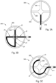
Figures 3 (A-C) are pictorial representation of smart heating systems constructed with a mounting bracket; -
Figures 4 (A-C) are pictorial representations and cross-sectional views of multiple heater elements used in a smart heating system in a diesel exhaust application; -
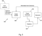
Figure 5 is a schematic representation of a smart heating system design, which is not an embodiment of the invention; -
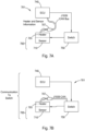
Figures 6 (A-B) are schematic representations of other smart heating systems designed to use heater information, wherein the smart heating system ofFigure 6(A) is not an embodiment of the invention; -
Figures 7 (A-B) are schematic representations of other smart heating systems designed to use heater and sensor information; and -
Figures 8 (A-B) are schematic representations of other smart heating systems designed with power switch control. - The following description is merely exemplary in nature and is in no way intended to limit the present disclosure or its application or uses. It should be understood that throughout the description, corresponding reference numerals indicate like or corresponding parts and features.
- The present disclosure generally relates to a smart heating system and a method of use associated therewith. The smart heating system made and used according to the teachings contained herein is described throughout the present disclosure in conjunction with diesel exhaust applications in order to more fully illustrate the concept. The incorporation and use of smart heating system in conjunction with other types of thermal management applications is contemplated to be within the scope of the disclosure.
- The following specific embodiments are given to illustrate the design and use of smart heating systems according to the teachings of the present disclosure and should not be construed to limit the scope of the disclosure. Those skilled-in-the-art, in light of the present disclosure, will appreciate that many changes can be made in the specific embodiments which are disclosed herein and still obtain alike or similar result without departing from or exceeding the scope of the disclosure. One skilled in the art will further understand that any properties reported herein represent properties that are routinely measured and can be obtained by multiple different methods. The methods described herein represent one such method and other methods may be utilized without exceeding the scope of the present disclosure.
- A smart heating system general comprises at least one heater element with predetermined (e.g., measured) or predictable performance characteristics. One example of such performance characteristics includes the rate of heating for the heater element when it is exposed to a preselected voltage or under a specified process flow condition. Although the average performance for multiple heater elements of the same or substantially similar design that are manufactured by the same process under similar process conditions represents valuable information, the measurement or knowledge of how each individual heater element in the system performs allows one to control the system's overall performance with respect to fast heating without sacrificing overall reliability. One specific example of a performance characteristic for a heater element that can be used to control a system's overall performance includes, without limitation, the locations associated with any non-uniformity in sheath temperature as shown by the temperature profile exhibited by the heating element under a known or predetermined flow/process condition.
- A smart heating system provides the benefits of enhanced diagnostic capability in addition to maximizing heat flux and lowering manufacturing cost. A robust diagnostic capability often depends on the variation exhibited from heater element to heater element. A system that is capable of using performance characteristics or information for specific heater elements provides for enhanced diagnostic capability by allowing at least a portion of the random variation that arises from manufacturing variances to be corrected or compensated for.
- The specific characteristics or information can be stored in any known format that is desirable, including but not limited to written text, bar codes, data matrix, and radio frequency identification (RFID), as well as being communicated on a digital bus or any other information or communication method known to one skilled in the art.
- According to one aspect of the present disclosure, the smart heating system may comprise at least one heater element or alternatively, a combination of at least one heater element and at least one temperature sensor. The sensor may be in contact with the sheath of the heater element (see
Figure 1A ), located on a bracket adjacent to the heater element, or located upstream or downstream of the heater element (seeFigure 1B ). The sensor is capable of measuring the temperature in a specific or desired location of the heater element. The measurement of temperature by the sensor allows the system to reduce power when the heater element is approaching or surpassing a predetermined temperature limit established according to the application being performed. - Referring to
Figures 1A and 1B , one specific combination of thesmart heating system 100 is shown that comprises atubular heater element 105 and athermocouple 110. Thethermocouple 110 can be in contact with or attached to the sheath of the heater element 105 (Figure 1A ) or located adjacent to the heater element 105 (Figure 1B ). One skilled in the art will understand that other types of heaters and sensors, may be used without exceeding the scope of the present disclosure. Optionally, thethermocouple 110 may be in communication with or attached to asignal conditioning module 115 that is capable of storing and/or processing information, such as, without limitation, sensor time response, sensor contact resistance to the heater's sheath, heater's maximum temperature limit, maximum ramp rate for the heater, heater resistance, and the heater's temperature profile or distribution map, as well as the difference in temperature between the heater and the area adjacent to the heater. The maximum temperature limit and the maximum ramp rate may be determined for aspecific heater element 105 andsensor 110 combination using conventional testing and inspection of the combination. - Since the
signal conditioning module 115 may comprise an input and output (I/O), an analog to digital converter (ADC), and a microprocessor, it is possible to use said module to make or communicate other measurements, including but not limited to, the magnitude of current leakage to ground, as well as the voltage and/or current applied to the heater. The measurement of current leakage is useful for determining if the heater insulation resistance (IR) is low and can be used to adjust the rate of applying voltage to the heater in order to remove moisture and/or extend the lifetime of the heater. The measurement of the applied voltage and/or current can be used to determine Power and heat flux associated with thesmart heating system 100, as well as to detect the occurrence of any defects or faults. - Still referring to
Figure 1 , asignal conditioning module 115 with digital communication capability may alternatively be used. Such digital communication capability may include the use of a local interconnect network (LIN) bus or controller area network (CAN) bus, as well as any other digital bus known to one skilled in the art. The digital bus receives measurements, such as temperature, current leakage, voltage, current, etc. from another device that is in communication with the bus through the use of anintegral connector 120, which in turn allows thesignal conditioning module 115 to become aware of and use this information instead of information that itself had measured. - According to another aspect of the present disclosure, the types of information collected and/or communicated may be utilized to enhance control of the heater system with respect to performance. For example, the information may be used to calculate (a) control parameters to avoid over temperature conditions associated with the heater; (b) a slow ramp for voltage at low current (I)-resistance (R) conditions in order to allow moisture to be evaporated; or (c) a diagnostic limit designed to prolong the lifetime of the heater system. An example of such a diagnostic limit (DL), may include the calculation of the change in temperature (ΔT) per unit time (Δt) per a predetermined variable (x) as shown in Equation 1. This predetermined variable (x) is selected based upon the specific application in which the smart heating system is being used. In certain applications, this variable (x) may be the applied voltage, the amount of fuel used, or the mass flow of an exhaust, among others.
-

- According to another aspect of the present disclosure, the smart heating system may comprise more than one temperature sensor. Referring now to
Figure 2 , asmart heating system 200 having aheater 205 in contact with more than onetemperature sensor 210, alternatively,multiple sensors 210, alternatively, at least threesensors 210 is shown. The use ofmultiple sensors 210 allows thesmart heating system 200 to measure temperature at several locations of theheater element 205, thereby, allowing calculation of differences in the measured locations. The calculation of these temperature differences provides for more precise control of theheater element 205 thereby increasing lifetime, as well as avoiding any damage resulting from localized over-heating. - In many applications, thermal gradients will exist in the environment to which the smart heating system is exposed. For example, thermal gradients may exist within a diesel oxidation catalyst (DOC) that can vary as a function of time and/or engine condition. Thermal gradients may also exist in other after treatment components, such as diesel particle filters (DPF), selective catalytic reducers, or lean NOx traps, among other components present in the exhaust stream that include an after-treatment catalyst. At least part of the function of an after-treatment catalyst is to facilitate a chemical reaction with the exhaust gases in order to reduce pollutants to comply with emission regulations. Since such chemical reactions have a dependency on temperature, a variation or gradient in temperature will affect the rate at which these reactions proceed. The use of a
smart heating system 200 can improve the performance of the after-treatment component by effectively controlling the temperature at a level that facilitates the occurrence of the chemical reaction. - Still referring to
Figure 2 , in a diesel exhaust system, asmart heating system 200 withmultiple sensors 210 is exposed to exhaust gases. In this application, thesmart heating system 200 can detect variations in temperature caused by thermal flow distribution of the exhaust gases and compensate or adjust accordingly in order to maximize the performance and/or lifetime of theheater element 205. Thus sensor information includes a measurement of temperature conditions in a location adjacent to theheater element 205. A similar arrangement with a single sensor is also shown inFigure 1B . The use ofmultiple sensors 210 can also be used to measure or predict additional diagnostic conditions when used in various applications. A few examples of which include the measurement of temperature gradients (i) downstream in a diesel particulate filter (DPF) in order to determine non-uniform soot build-up in the DPF; (ii) downstream of a diesel oxidation catalyst (DOC) in order to identify the occurrence of non-uniform oxidation or face-plugging of the DOC; and (iii) upstream of a DOC in order to identify non-uniform temperatures so that more accurate energy balance calculations can be obtained. - According to another aspect of the present disclosure, the smart heating system may further comprise a support bracket. In some applications, such as in a diesel exhaust system, among others, the vibrations arising from the application may be to such a degree that at least one support bracket is necessary to mount the smart heating system. Referring now to
Figures 3(A) , each mountingbracket 330 may be used to support aheating element 305 of thesmart heating system 300. When desirable thetemperature sensor 310 may also be supported by one of thebrackets 330. Whenmultiple sensors 310 are utilized, eachsensor 310 may be in contact with abracket 330. - Alternatively, a
junction sensor 311 may be utilized (Figures 3B & 3C ) withsuch sensor 311 being in contact with thebracket 330 in multiple locations. Ajunction sensor 311 provides multiple temperature measurements. As shown inFigure 3B , thespecific junction sensor 311 shown provides for a temperature measurement at the center of the heater can (junction J1) and at four other locations (junctions J2-J5). InFigure 3C , asmart heating system 300 is shown with abracket 330 providing support for aheater element 305 and ajunction sensor 311 that provides for temperature measurement at three locations (junctions J1-J3). One skilled in the art will understand that many otherdifferent sensors bracket 330 combinations may be utilized without exceeding the scope of the present disclosure. - In general, a
smart heating system 300 that hasmultiple sensors single sensor 310. The use of ajunction sensor 311 may become a lower cost alternative as compared to the use of multipleindividual sensors 310. - Referring now to
Figures 4 (A-C), the smart heating system 400 may comprisemultiple heater elements 405. InFigure 4A , multiplecirculation heater elements 405 having a U-shaped bend are shown in anexhaust component 411. InFigures 4B and 4C , multiplecirculation heater elements 405 are shown that have a circular shape.Multiple heater elements 405 can be used to create a desired temperature profile. For example, all of theheater elements 405 could be powered at the same time or alternated such that an uniform temperature is established in the exhaust / aftertreatment system 411 in order to facilitate the chemical reaction. Alternatively, some of theheater elements 405 can be fabricated and powered at different levels in order to create a different amount of heat and to modify the thermal gradient that exists within the exhaust or aftertreatment component 411. Several specific examples in which heater elements create different amounts of heat include (a) providingheater elements 405 located on the periphery with a different amount of power than those located in the interior of theexhaust component 411; and (b) providingheater elements 405 located in different quadrants with in theexhaust component 411 in order to control thermal gradients on a quadrant by quadrant basis. Alternatively,heater elements 405 may be placed only around the periphery of theexhaust component 411 in order to establish a single heating zone that can be used to reduce or improve radial temperature gradients. - Similar to the use of multiple heaters, the use of multiple sensors located in predetermined places based on their ability to add value in measuring the thermal gradient. The temperature sensors can be thermocouples, thermistors, resistance temperature devices, and any other known means of measuring or detecting temperature. A heater element having a resistance that varies with temperature may be used as a 2-wire heater/sensor combination. The heater element may include without limitation cable heaters, tubular heaters, cartridge heaters, flexible heaters, layered heaters, metal foils, metal fleece heaters, or any other type of heater known to one skilled in the art.
- Referring now to
Figure 5 , one specific example of asmart heating system 500 designed for controlling temperature is shown. In thissystem 500 design, theheater element 505 receives power from aswitch 550 that can be actuated using signal(s) from theheater control unit 560. Theheater control unit 560 receives information from one ormore sensors 510 and/or anelectronic control unit 540. Based on the information, theheater control unit 560 communicates with thepower switch 550 and relays the power to theheater element 505. Thepower switch 550 relays may be integrated into theheater control unit 540 when desirable. Theheater elements 505 are distributed so that they are capable of providing a preferred or desirable temperature profile in the after treatment exhaust system in order to enhance performance of the after treatment system. Enhanced performance with respect to a diesel exhaust system includes without limitation improved NOx production by the diesel oxidation catalyst (DOC) or in a catalyzed diesel particulate filter (DPF); improving ammonia storage or NOx conversion, or improving other chemical reactions. - During the construction of a smart heating system, the heater may be mounted with the information related to the heater attached to the heater assembly via a barcode, data matrix, RFID tag, or any other known method. Such heater information may include, among others, rating of heating, resistance, maximum voltage as a function of time, etc. Referring now to
Figure 6A , thesmart heating system 600 may be utilized via an openloop control mechanism 601. In thismechanism 601, thesmart heating system 600, which includes aheater 605 along with itsrelated information 607, is in communication with an electronic control unit (ECU) 640. Theheater information 607 may be either manually or automatically communicated to theECU 640 or to aswitching device 650 to enable better use of theheater 605. A similar benefit associated with using theheater information 607 equally applies to a closedloop control mechanism 602 as described inFigure 6B that incorporates anexternal temperature sensor 611. - Alternatively, a smart heating system can be utilized that includes information about both the heater and temperature sensor(s). Referring now to
Figures 7A and 7B , asmart heating system 700 that includes both aheater 705 and sensor 710 combination that is marked with both heater andsensor information 707 as previously described above for asmart heating system 600 that includes only heater information 607 (seeFigure 6 ) or if the sensor is an active sensor with a signal conditioning module (not shown), theinformation 707 may be stored in the memory of the conditioning module. The heater-sensor information 707 is communicated to an ECU 740 (Figure 7A ) or to a power switch 750 (Figure 7B ) in order to enhance the utilization of thesmart heating system 700. Although thesmart heating system 700 is shown inFigures 7A & 7B to be utilized in a closedloop control mechanism 701, one skilled in the art will understand that an open loop control mechanism (not shown) may also be utilized as another option. - Referring now to
Figure 8A , a third option for using heater-sensor information 807 is to communicate thisinformation 807 to anothercontrol unit 860 that controls the functionality of thepower switch 850. Optionally, theswitch control 860 may also be in communication with theECU 840. Alternatively, as shown inFigure 8B , theinformation 808 concerning theswitch 850 can be incorporated with theswitch control 860 for use along with the heater-sensor information. - Still referring to
Figure 8(B) , theswitch information 808 may include without limitation, a measurement of the current and/or voltage, as well as the rate of heating associated with the solid state components of theswitch 850 as a function of the amount of electrical current that is being switched. The rate of heating associated with thesensor 810 junction in contact with theswitch 850 can be determined based on the electrical current (I) and the ability of theswitch 850 to dissipate heat away from the junction. One skilled in the art will understand the relationship of this current (I) to the resistance (R) associated with aheater element 805 resulting in what is known as I2R heating. Thus the current to temperature relationship of theheater element 805 can be measured and stored asheater information 807. At a predetermined fluid flow condition, which can be communicated to theECU 840, thesmart heater system 800 comprising aheater 805,sensor 810, and switch 850 can be used to compare the rate of fluid temperature change to the rate of change in theswitch 850 temperature in order to diagnose if thesystem 600 is operating efficiently. - The foregoing description of various forms of the invention has been presented for purposes of illustration and description. It is not intended to be exhaustive or to limit the invention to the precise forms disclosed. Numerous modifications or variations are possible in light of the above teachings. The forms discussed were chosen and described to provide the best illustration of the principles of the invention and its practical application to thereby enable one of ordinary skill in the art to utilize the invention in various forms and with various modifications as are suited to the particular use contemplated. All such modifications and variations are within the scope of the invention as determined by the appended claims when interpreted in accordance with the breadth to which they are fairly, legally, and equitably entitled.
Claims (12)
- A smart heating system (600, 700, 800) comprising: one heater element (605, 705, 805), one temperature sensor (611, 710, 810), one switch (650, 750, 850) connected to the heater element (605, 705, 805), and a heater control unit (640, 740, 840),
characterized in that the smart heating system (600, 700, 800) further comprises a set of predetermined performance information (607, 707, 807) including heater information specific for the heater element (605, 705, 805), wherein the heater control unit (640, 740, 840) controls the heater element (605, 705, 805) via the switch (650, 750, 850) based on the heater information and information from the temperature sensor (611, 710, 810). - The smart heating system (600, 700, 800) according to claim 1, wherein the smart heating system (600, 700, 800) further comprises at least one support bracket (330) in contact with the heater element (605, 705, 805) and optionally with the temperature sensor (611, 710, 810).
- The smart heating system (600, 700, 800) according any of Claims 1 or 2, wherein the set of predetermined performance information (607, 707, 807) includes sensor information, and optionally switch information.
- The smart heating system (600, 700, 800) according to any of preceding claims, wherein the set of predetermined performance information (607, 707, 807) includes a rate of heating at a desired voltage or under a specified flow condition, heater resistance, heater or sensor stability, flow uniformity or temperature conditions in a location adjacent to the heater element (605, 705, 805).
- The smart heating system (600, 700, 800) according to any of preceding claims, wherein the smart heating system includes a plurality of temperature sensors (611, 710, 810), the plurality of temperature sensors (611, 710, 810) being a combination of individual sensors or a multiple junction sensor capable of providing more than one temperature measurement.
- The smart heating system (600, 700, 800) according to any of preceding claims, wherein the temperature sensor (611, 710, 810) is selected as a thermocouple, a thermistor, or a resistance temperature device.
- The smart heating system (600, 700, 800) according to any of preceding claims, wherein the heater element (605, 705, 805) is selected as a cable heater, a tubular heater, a cartridge heater, a flexible heater, a layered heater, a metal foil, or a metal fleece heater.
- The smart heating system (600, 700, 800) according to any of preceding claims, wherein the set of predetermined performance information (607, 707, 807) is stored as written text, a bar code, a data matrix, a radio frequency identification (RFID) tag, or in memory of a conditioning module.
- The smart heating system (600, 700, 800) according to any of preceding claims, further comprising a LIN or a CAN bus capable of providing a communication pathway between at least two system components.
- The smart heating system (600, 700, 800) according to any of preceding claims, wherein the heater control unit (640, 740, 840) is configured to compensate for a thermal gradient present in a diesel oxidation catalyst (DOC), diesel particle filter (DPF), selective catalytic reducer (SCR), lean NOx traps, or another exhaust component that includes an after-treatment catalyst.
- The smart heating system (600, 700, 800) according to any of preceding claims, wherein the heater control unit (640, 740, 840) establishes thermal control by creating a desired temperature profile; the temperature profile being created by providing power to the heater element (605, 705, 805) in the smart heating system.
- An exhaust gas treatment system, that includes a smart heating system (600, 700, 800) according to any of preceding claims.
Applications Claiming Priority (2)
| Application Number | Priority Date | Filing Date | Title |
|---|---|---|---|
| US201361816346P | 2013-04-26 | 2013-04-26 | |
| PCT/US2014/035645 WO2014176585A1 (en) | 2013-04-26 | 2014-04-28 | Smart heating system |
Publications (3)
| Publication Number | Publication Date |
|---|---|
| EP2989304A1 EP2989304A1 (en) | 2016-03-02 |
| EP2989304C0 EP2989304C0 (en) | 2024-12-11 |
| EP2989304B1 true EP2989304B1 (en) | 2024-12-11 |
Family
ID=50897903
Family Applications (1)
| Application Number | Title | Priority Date | Filing Date |
|---|---|---|---|
| EP14729132.2A Active EP2989304B1 (en) | 2013-04-26 | 2014-04-28 | Smart heating system |
Country Status (6)
| Country | Link |
|---|---|
| US (2) | US20140343747A1 (en) |
| EP (1) | EP2989304B1 (en) |
| JP (1) | JP6454687B2 (en) |
| CN (1) | CN105143621B (en) |
| CA (1) | CA2908699C (en) |
| WO (1) | WO2014176585A1 (en) |
Families Citing this family (22)
| Publication number | Priority date | Publication date | Assignee | Title |
|---|---|---|---|---|
| CN103066662B (en) * | 2013-01-07 | 2015-08-05 | 雷星亮 | emergency power supply |
| US10251217B2 (en) * | 2013-06-14 | 2019-04-02 | Sandvik Kk | Molybdenum disilicide-based ceramic heating element holding structure |
| US20150075145A1 (en) * | 2013-09-19 | 2015-03-19 | Bryan Alan Yonan | Diesel Dissipation Dryer Device |
| US9702284B2 (en) * | 2015-01-15 | 2017-07-11 | Tenneco Automotive Operating Company Inc. | System and method for detecting face-plugging of an exhaust aftertreatment component |
| US10125658B2 (en) | 2015-08-05 | 2018-11-13 | Tenneco Automotive Operating Company Inc. | Particulate sensor assembly |
| JP6686134B2 (en) * | 2015-10-01 | 2020-04-22 | ワトロー エレクトリック マニュファクチュアリング カンパニー | Integrated device and method for enhancing heater life and performance |
| JP7091249B2 (en) | 2016-03-02 | 2022-06-27 | ワットロー・エレクトリック・マニュファクチャリング・カンパニー | Heater operation flow bypass |
| WO2017151975A1 (en) * | 2016-03-02 | 2017-09-08 | Watlow Electric Manufacturing Company | Bare heating elements for heating fluid flows |
| US20170276527A1 (en) * | 2016-03-25 | 2017-09-28 | General Electric Company | System and method for metering gas |
| US10323556B2 (en) | 2016-12-16 | 2019-06-18 | Gates Corporation | Electric immersion heater for diesel exhaust fluid reservoir |
| DE102017100500A1 (en) * | 2017-01-12 | 2018-07-12 | Volkswagen Aktiengesellschaft | Process for the regeneration of a particulate filter |
| FR3065028B1 (en) * | 2017-04-07 | 2019-12-20 | Faurecia Systemes D'echappement | METHOD FOR PURIFYING EXHAUST GASES FROM A VEHICLE, CORRESPONDING PURIFICATION DEVICE |
| FR3065027B1 (en) * | 2017-04-07 | 2019-11-29 | Faurecia Systemes D'echappement | VEHICLE EXHAUST GAS PURIFYING DEVICE AND CORRESPONDING DRIVING METHOD |
| FR3077330B1 (en) * | 2018-02-01 | 2020-03-13 | Faurecia Systemes D'echappement | EASY-HANDLING HEATER FOR VEHICLE EXHAUST GAS PURIFICATION DEVICE |
| FR3086973B1 (en) * | 2018-10-05 | 2021-01-22 | Faurecia Systemes Dechappement | EXHAUST GAS HEATING DEVICE, ESPECIALLY FOR A COMBUSTION ENGINE, INCLUDING A GRILLE CARRIED BY ELECTRIC CURRENT |
| DE102018221643A1 (en) * | 2018-12-13 | 2020-06-18 | Robert Bosch Gmbh | Method for heating an exhaust system of an internal combustion engine of a motor vehicle |
| US10975746B1 (en) * | 2019-12-12 | 2021-04-13 | GM Global Technology Operations LLC | Varying closed loop gain control to constrain ramp rate of oxygen sensors in exhaust systems |
| DE102021113989A1 (en) | 2021-05-31 | 2022-12-01 | Purem GmbH | exhaust heater |
| DE102022206430A1 (en) | 2021-06-29 | 2022-12-29 | Cummins Emission Solutions Inc. | Systems and methods for reducing NOx emissions from aftertreatment systems |
| DE102021210761A1 (en) | 2021-09-27 | 2023-03-30 | Vitesco Technologies GmbH | Heating conductor for heating an exhaust gas stream of an internal combustion engine |
| DE102021133131A1 (en) * | 2021-12-14 | 2023-06-15 | Ford Global Technologies, Llc | motor vehicle |
| US12357957B2 (en) | 2023-12-14 | 2025-07-15 | First Ammonia Motors, Inc. | System and method for a three-dimensionally printed lattice structure for heating gas in a non-linear path |
Family Cites Families (30)
| Publication number | Priority date | Publication date | Assignee | Title |
|---|---|---|---|---|
| US3607131A (en) * | 1969-02-05 | 1971-09-21 | Us Navy | Catalytic air purifier |
| DE2239549C3 (en) * | 1972-08-11 | 1975-02-13 | Adam Opel Ag, 6090 Ruesselsheim | Excess temperature display and protection device, especially in catalytically active exhaust gas decontamination systems for internal combustion engines |
| US3905873A (en) * | 1973-09-24 | 1975-09-16 | Standard Oil Co Ohio | Control apparatus for fractionation tower |
| US4395309A (en) * | 1980-11-03 | 1983-07-26 | Esztergar Ernest P | Fractional distillation of hydrocarbons from coal |
| US4549398A (en) * | 1981-06-22 | 1985-10-29 | Toyota Jidosha Kogyo Kabushiki Kaisha | Exhaust gas cleaning device for diesel engines |
| US4723973A (en) * | 1985-09-28 | 1988-02-09 | Nippondenso Co., Ltd. | Purifying apparatus of a particulate trap-type for collecting particulates in exhaust gas from an engine |
| JP3147372B2 (en) * | 1990-10-10 | 2001-03-19 | 株式会社日本自動車部品総合研究所 | Exhaust gas particulate collection filter |
| JP2544579Y2 (en) * | 1991-03-31 | 1997-08-20 | 川崎重工業株式会社 | Film coating equipment for structures |
| FR2702516B1 (en) * | 1993-03-12 | 1995-06-02 | Siemens Automotive Sa | Method for monitoring the efficiency of a heated catalytic converter, for the treatment of exhaust gases from an internal combustion engine. |
| JPH06330733A (en) * | 1993-05-21 | 1994-11-29 | Toyota Motor Corp | Exhaust particulates remover of diesel engine |
| JPH0783215A (en) * | 1993-09-16 | 1995-03-28 | Moriden:Kk | Attaching bracket |
| US5983627A (en) * | 1997-09-02 | 1999-11-16 | Ford Global Technologies, Inc. | Closed loop control for desulfating a NOx trap |
| US6232585B1 (en) * | 1998-05-19 | 2001-05-15 | Thermal Solutions, Inc. | Temperature self-regulating food delivery system |
| EP1291741B1 (en) * | 2000-04-14 | 2012-05-09 | Omron Corporation | Controller, temperature regulator, and heat treatment apparatus |
| JP3719148B2 (en) * | 2001-02-08 | 2005-11-24 | トヨタ自動車株式会社 | Catalyst temperature raising device for internal combustion engine |
| JP4403944B2 (en) * | 2004-01-13 | 2010-01-27 | 株式会社デンソー | Exhaust gas purification device for internal combustion engine |
| EP1787179A2 (en) * | 2004-08-31 | 2007-05-23 | Watlow Electric Manufacturing Company | Operations system distributed diagnostic system |
| US20060096244A1 (en) * | 2004-11-09 | 2006-05-11 | Aetna Group S.P.A. | Machine for banding groups of palletized products |
| ATE420708T1 (en) * | 2005-03-04 | 2009-01-15 | Donaldson Co Inc | DEVICE FOR BURNING COLLECTED DIESEL EXHAUST MATERIAL FROM AN AFTERTREATMENT DEVICE AND METHOD |
| JP4501877B2 (en) * | 2006-03-14 | 2010-07-14 | 株式会社デンソー | Control device for internal combustion engine |
| US8117832B2 (en) * | 2006-06-19 | 2012-02-21 | Donaldson Company, Inc. | Exhaust treatment device with electric regeneration system |
| JP2008255812A (en) * | 2007-04-02 | 2008-10-23 | Fuji Heavy Ind Ltd | Exhaust gas purification device for internal combustion engine |
| US20090107117A1 (en) * | 2007-10-30 | 2009-04-30 | Ford Global Technologies, Llc | Diesel Engine Aftertreatment Control Operation with Waste Heat Recovery |
| US8444729B2 (en) * | 2007-11-26 | 2013-05-21 | Caterpillar Inc. | Electrically regenerated exhaust particulate filter having non-axial regeneration flame propagation |
| US20090293457A1 (en) * | 2008-05-30 | 2009-12-03 | Grichnik Anthony J | System and method for controlling NOx reactant supply |
| US8205439B2 (en) * | 2009-01-23 | 2012-06-26 | GM Global Technology Operations LLC | Electrically heated particulate filter with zoned exhaust flow control |
| EP3192991B1 (en) * | 2012-02-22 | 2019-04-24 | Watlow Electric Manufacturing Company | Method of heating an exhaust gas in an exhaust aftertreatment system |
| DE102012203401A1 (en) * | 2012-03-05 | 2013-09-05 | Volkswagen Aktiengesellschaft | Method for controlling a heating device for heating a component, control device and motor vehicle with such |
| JP5697630B2 (en) * | 2012-05-31 | 2015-04-08 | キヤノン株式会社 | Image forming apparatus |
| US9599973B2 (en) * | 2013-03-14 | 2017-03-21 | International Business Machines Corporation | Interactive energy device for environmental stewardship |
-
2014
- 2014-04-28 CA CA2908699A patent/CA2908699C/en active Active
- 2014-04-28 US US14/263,177 patent/US20140343747A1/en not_active Abandoned
- 2014-04-28 WO PCT/US2014/035645 patent/WO2014176585A1/en not_active Ceased
- 2014-04-28 CN CN201480023417.8A patent/CN105143621B/en active Active
- 2014-04-28 EP EP14729132.2A patent/EP2989304B1/en active Active
- 2014-04-28 JP JP2016510821A patent/JP6454687B2/en active Active
-
2020
- 2020-02-10 US US16/786,218 patent/US11550346B2/en active Active
Also Published As
| Publication number | Publication date |
|---|---|
| JP6454687B2 (en) | 2019-01-16 |
| CN105143621B (en) | 2020-08-07 |
| WO2014176585A1 (en) | 2014-10-30 |
| EP2989304C0 (en) | 2024-12-11 |
| US20140343747A1 (en) | 2014-11-20 |
| CA2908699C (en) | 2018-11-13 |
| CA2908699A1 (en) | 2014-10-30 |
| EP2989304A1 (en) | 2016-03-02 |
| US11550346B2 (en) | 2023-01-10 |
| US20200174505A1 (en) | 2020-06-04 |
| CN105143621A (en) | 2015-12-09 |
| JP2016526249A (en) | 2016-09-01 |
Similar Documents
| Publication | Publication Date | Title |
|---|---|---|
| US11550346B2 (en) | Smart heater system | |
| JP7238176B2 (en) | How the heater system works | |
| US11415036B2 (en) | Apparatus and method for ascertaining a heating temperature of a heating element for an electrically heatable catalytic converter | |
| CN110849494B (en) | Active grounding thermocouple and operation method | |
| CN115478930B (en) | Exhaust gas heater | |
| CA3016553C (en) | Dual-purpose heater and fluid flow measurement system |
Legal Events
| Date | Code | Title | Description |
|---|---|---|---|
| PUAI | Public reference made under article 153(3) epc to a published international application that has entered the european phase |
Free format text: ORIGINAL CODE: 0009012 |
|
| 17P | Request for examination filed |
Effective date: 20151021 |
|
| AK | Designated contracting states |
Kind code of ref document: A1 Designated state(s): AL AT BE BG CH CY CZ DE DK EE ES FI FR GB GR HR HU IE IS IT LI LT LU LV MC MK MT NL NO PL PT RO RS SE SI SK SM TR |
|
| AX | Request for extension of the european patent |
Extension state: BA ME |
|
| DAX | Request for extension of the european patent (deleted) | ||
| STAA | Information on the status of an ep patent application or granted ep patent |
Free format text: STATUS: EXAMINATION IS IN PROGRESS |
|
| 17Q | First examination report despatched |
Effective date: 20180315 |
|
| GRAP | Despatch of communication of intention to grant a patent |
Free format text: ORIGINAL CODE: EPIDOSNIGR1 |
|
| STAA | Information on the status of an ep patent application or granted ep patent |
Free format text: STATUS: GRANT OF PATENT IS INTENDED |
|
| INTG | Intention to grant announced |
Effective date: 20240410 |
|
| GRAJ | Information related to disapproval of communication of intention to grant by the applicant or resumption of examination proceedings by the epo deleted |
Free format text: ORIGINAL CODE: EPIDOSDIGR1 |
|
| STAA | Information on the status of an ep patent application or granted ep patent |
Free format text: STATUS: EXAMINATION IS IN PROGRESS |
|
| GRAP | Despatch of communication of intention to grant a patent |
Free format text: ORIGINAL CODE: EPIDOSNIGR1 |
|
| STAA | Information on the status of an ep patent application or granted ep patent |
Free format text: STATUS: GRANT OF PATENT IS INTENDED |
|
| INTC | Intention to grant announced (deleted) | ||
| INTG | Intention to grant announced |
Effective date: 20240816 |
|
| GRAS | Grant fee paid |
Free format text: ORIGINAL CODE: EPIDOSNIGR3 |
|
| GRAA | (expected) grant |
Free format text: ORIGINAL CODE: 0009210 |
|
| STAA | Information on the status of an ep patent application or granted ep patent |
Free format text: STATUS: THE PATENT HAS BEEN GRANTED |
|
| AK | Designated contracting states |
Kind code of ref document: B1 Designated state(s): AL AT BE BG CH CY CZ DE DK EE ES FI FR GB GR HR HU IE IS IT LI LT LU LV MC MK MT NL NO PL PT RO RS SE SI SK SM TR |
|
| REG | Reference to a national code |
Ref country code: GB Ref legal event code: FG4D |
|
| REG | Reference to a national code |
Ref country code: CH Ref legal event code: EP |
|
| REG | Reference to a national code |
Ref country code: IE Ref legal event code: FG4D |
|
| REG | Reference to a national code |
Ref country code: DE Ref legal event code: R096 Ref document number: 602014091310 Country of ref document: DE |
|
| U01 | Request for unitary effect filed |
Effective date: 20250108 |
|
| U07 | Unitary effect registered |
Designated state(s): AT BE BG DE DK EE FI FR IT LT LU LV MT NL PT RO SE SI Effective date: 20250116 |
|
| PG25 | Lapsed in a contracting state [announced via postgrant information from national office to epo] |
Ref country code: HR Free format text: LAPSE BECAUSE OF FAILURE TO SUBMIT A TRANSLATION OF THE DESCRIPTION OR TO PAY THE FEE WITHIN THE PRESCRIBED TIME-LIMIT Effective date: 20241211 |
|
| PG25 | Lapsed in a contracting state [announced via postgrant information from national office to epo] |
Ref country code: ES Free format text: LAPSE BECAUSE OF FAILURE TO SUBMIT A TRANSLATION OF THE DESCRIPTION OR TO PAY THE FEE WITHIN THE PRESCRIBED TIME-LIMIT Effective date: 20241211 |
|
| PG25 | Lapsed in a contracting state [announced via postgrant information from national office to epo] |
Ref country code: NO Free format text: LAPSE BECAUSE OF FAILURE TO SUBMIT A TRANSLATION OF THE DESCRIPTION OR TO PAY THE FEE WITHIN THE PRESCRIBED TIME-LIMIT Effective date: 20250311 |
|
| PG25 | Lapsed in a contracting state [announced via postgrant information from national office to epo] |
Ref country code: GR Free format text: LAPSE BECAUSE OF FAILURE TO SUBMIT A TRANSLATION OF THE DESCRIPTION OR TO PAY THE FEE WITHIN THE PRESCRIBED TIME-LIMIT Effective date: 20250312 |
|
| PG25 | Lapsed in a contracting state [announced via postgrant information from national office to epo] |
Ref country code: RS Free format text: LAPSE BECAUSE OF FAILURE TO SUBMIT A TRANSLATION OF THE DESCRIPTION OR TO PAY THE FEE WITHIN THE PRESCRIBED TIME-LIMIT Effective date: 20250311 |
|
| U20 | Renewal fee for the european patent with unitary effect paid |
Year of fee payment: 12 Effective date: 20250428 |
|
| PG25 | Lapsed in a contracting state [announced via postgrant information from national office to epo] |
Ref country code: SM Free format text: LAPSE BECAUSE OF FAILURE TO SUBMIT A TRANSLATION OF THE DESCRIPTION OR TO PAY THE FEE WITHIN THE PRESCRIBED TIME-LIMIT Effective date: 20241211 |
|
| PG25 | Lapsed in a contracting state [announced via postgrant information from national office to epo] |
Ref country code: PL Free format text: LAPSE BECAUSE OF FAILURE TO SUBMIT A TRANSLATION OF THE DESCRIPTION OR TO PAY THE FEE WITHIN THE PRESCRIBED TIME-LIMIT Effective date: 20241211 |
|
| PGFP | Annual fee paid to national office [announced via postgrant information from national office to epo] |
Ref country code: GB Payment date: 20250428 Year of fee payment: 12 |
|
| PG25 | Lapsed in a contracting state [announced via postgrant information from national office to epo] |
Ref country code: IS Free format text: LAPSE BECAUSE OF FAILURE TO SUBMIT A TRANSLATION OF THE DESCRIPTION OR TO PAY THE FEE WITHIN THE PRESCRIBED TIME-LIMIT Effective date: 20250411 |
|
| PG25 | Lapsed in a contracting state [announced via postgrant information from national office to epo] |
Ref country code: SK Free format text: LAPSE BECAUSE OF FAILURE TO SUBMIT A TRANSLATION OF THE DESCRIPTION OR TO PAY THE FEE WITHIN THE PRESCRIBED TIME-LIMIT Effective date: 20241211 |
|
| PG25 | Lapsed in a contracting state [announced via postgrant information from national office to epo] |
Ref country code: CZ Free format text: LAPSE BECAUSE OF FAILURE TO SUBMIT A TRANSLATION OF THE DESCRIPTION OR TO PAY THE FEE WITHIN THE PRESCRIBED TIME-LIMIT Effective date: 20241211 |
|
| PLBE | No opposition filed within time limit |
Free format text: ORIGINAL CODE: 0009261 |
|
| STAA | Information on the status of an ep patent application or granted ep patent |
Free format text: STATUS: NO OPPOSITION FILED WITHIN TIME LIMIT |
|
| REG | Reference to a national code |
Ref country code: CH Ref legal event code: L10 Free format text: ST27 STATUS EVENT CODE: U-0-0-L10-L00 (AS PROVIDED BY THE NATIONAL OFFICE) Effective date: 20251022 |
|
| 26N | No opposition filed |
Effective date: 20250912 |
|
| REG | Reference to a national code |
Ref country code: CH Ref legal event code: H13 Free format text: ST27 STATUS EVENT CODE: U-0-0-H10-H13 (AS PROVIDED BY THE NATIONAL OFFICE) Effective date: 20251125 |
|
| PG25 | Lapsed in a contracting state [announced via postgrant information from national office to epo] |
Ref country code: MC Free format text: LAPSE BECAUSE OF FAILURE TO SUBMIT A TRANSLATION OF THE DESCRIPTION OR TO PAY THE FEE WITHIN THE PRESCRIBED TIME-LIMIT Effective date: 20241211 |
|
| PG25 | Lapsed in a contracting state [announced via postgrant information from national office to epo] |
Ref country code: CH Free format text: LAPSE BECAUSE OF NON-PAYMENT OF DUE FEES Effective date: 20250430 |
|
| PG25 | Lapsed in a contracting state [announced via postgrant information from national office to epo] |
Ref country code: IE Free format text: LAPSE BECAUSE OF NON-PAYMENT OF DUE FEES Effective date: 20250428 |