EP2988479A1 - Capacitive proximity sensor and mobile device - Google Patents
Capacitive proximity sensor and mobile device Download PDFInfo
- Publication number
- EP2988479A1 EP2988479A1 EP15180782.3A EP15180782A EP2988479A1 EP 2988479 A1 EP2988479 A1 EP 2988479A1 EP 15180782 A EP15180782 A EP 15180782A EP 2988479 A1 EP2988479 A1 EP 2988479A1
- Authority
- EP
- European Patent Office
- Prior art keywords
- region
- electrode
- body portion
- proximity
- capacitive
- Prior art date
- Legal status (The legal status is an assumption and is not a legal conclusion. Google has not performed a legal analysis and makes no representation as to the accuracy of the status listed.)
- Granted
Links
Images



Classifications
-
- H—ELECTRICITY
- H04—ELECTRIC COMMUNICATION TECHNIQUE
- H04W—WIRELESS COMMUNICATION NETWORKS
- H04W4/00—Services specially adapted for wireless communication networks; Facilities therefor
- H04W4/02—Services making use of location information
- H04W4/023—Services making use of location information using mutual or relative location information between multiple location based services [LBS] targets or of distance thresholds
-
- G—PHYSICS
- G06—COMPUTING OR CALCULATING; COUNTING
- G06F—ELECTRIC DIGITAL DATA PROCESSING
- G06F3/00—Input arrangements for transferring data to be processed into a form capable of being handled by the computer; Output arrangements for transferring data from processing unit to output unit, e.g. interface arrangements
- G06F3/01—Input arrangements or combined input and output arrangements for interaction between user and computer
- G06F3/03—Arrangements for converting the position or the displacement of a member into a coded form
- G06F3/041—Digitisers, e.g. for touch screens or touch pads, characterised by the transducing means
- G06F3/044—Digitisers, e.g. for touch screens or touch pads, characterised by the transducing means by capacitive means
- G06F3/0445—Digitisers, e.g. for touch screens or touch pads, characterised by the transducing means by capacitive means using two or more layers of sensing electrodes, e.g. using two layers of electrodes separated by a dielectric layer
-
- G—PHYSICS
- G01—MEASURING; TESTING
- G01B—MEASURING LENGTH, THICKNESS OR SIMILAR LINEAR DIMENSIONS; MEASURING ANGLES; MEASURING AREAS; MEASURING IRREGULARITIES OF SURFACES OR CONTOURS
- G01B7/00—Measuring arrangements characterised by the use of electric or magnetic techniques
- G01B7/14—Measuring arrangements characterised by the use of electric or magnetic techniques for measuring distance or clearance between spaced objects or spaced apertures
-
- G—PHYSICS
- G06—COMPUTING OR CALCULATING; COUNTING
- G06F—ELECTRIC DIGITAL DATA PROCESSING
- G06F1/00—Details not covered by groups G06F3/00 - G06F13/00 and G06F21/00
- G06F1/26—Power supply means, e.g. regulation thereof
- G06F1/32—Means for saving power
-
- G—PHYSICS
- G06—COMPUTING OR CALCULATING; COUNTING
- G06F—ELECTRIC DIGITAL DATA PROCESSING
- G06F3/00—Input arrangements for transferring data to be processed into a form capable of being handled by the computer; Output arrangements for transferring data from processing unit to output unit, e.g. interface arrangements
- G06F3/01—Input arrangements or combined input and output arrangements for interaction between user and computer
- G06F3/011—Arrangements for interaction with the human body, e.g. for user immersion in virtual reality
-
- G—PHYSICS
- G06—COMPUTING OR CALCULATING; COUNTING
- G06F—ELECTRIC DIGITAL DATA PROCESSING
- G06F3/00—Input arrangements for transferring data to be processed into a form capable of being handled by the computer; Output arrangements for transferring data from processing unit to output unit, e.g. interface arrangements
- G06F3/01—Input arrangements or combined input and output arrangements for interaction between user and computer
- G06F3/03—Arrangements for converting the position or the displacement of a member into a coded form
- G06F3/041—Digitisers, e.g. for touch screens or touch pads, characterised by the transducing means
- G06F3/044—Digitisers, e.g. for touch screens or touch pads, characterised by the transducing means by capacitive means
-
- H—ELECTRICITY
- H03—ELECTRONIC CIRCUITRY
- H03K—PULSE TECHNIQUE
- H03K17/00—Electronic switching or gating, i.e. not by contact-making and –breaking
- H03K17/94—Electronic switching or gating, i.e. not by contact-making and –breaking characterised by the way in which the control signals are generated
- H03K17/945—Proximity switches
- H03K17/955—Proximity switches using a capacitive detector
-
- H—ELECTRICITY
- H04—ELECTRIC COMMUNICATION TECHNIQUE
- H04M—TELEPHONIC COMMUNICATION
- H04M1/00—Substation equipment, e.g. for use by subscribers
- H04M1/02—Constructional features of telephone sets
- H04M1/0202—Portable telephone sets, e.g. cordless phones, mobile phones or bar type handsets
- H04M1/026—Details of the structure or mounting of specific components
-
- H—ELECTRICITY
- H03—ELECTRONIC CIRCUITRY
- H03K—PULSE TECHNIQUE
- H03K17/00—Electronic switching or gating, i.e. not by contact-making and –breaking
- H03K17/94—Electronic switching or gating, i.e. not by contact-making and –breaking characterised by the way in which the control signals are generated
- H03K17/96—Touch switches
- H03K2017/9602—Touch switches characterised by the type or shape of the sensing electrodes
- H03K2017/9604—Touch switches characterised by the type or shape of the sensing electrodes characterised by the number of electrodes
- H03K2017/9613—Touch switches characterised by the type or shape of the sensing electrodes characterised by the number of electrodes using two electrodes per touch switch
-
- H—ELECTRICITY
- H03—ELECTRONIC CIRCUITRY
- H03K—PULSE TECHNIQUE
- H03K2217/00—Indexing scheme related to electronic switching or gating, i.e. not by contact-making or -breaking covered by H03K17/00
- H03K2217/94—Indexing scheme related to electronic switching or gating, i.e. not by contact-making or -breaking covered by H03K17/00 characterised by the way in which the control signal is generated
- H03K2217/96—Touch switches
- H03K2217/9607—Capacitive touch switches
- H03K2217/960755—Constructional details of capacitive touch and proximity switches
- H03K2217/960765—Details of shielding arrangements
-
- H—ELECTRICITY
- H04—ELECTRIC COMMUNICATION TECHNIQUE
- H04M—TELEPHONIC COMMUNICATION
- H04M2250/00—Details of telephonic subscriber devices
- H04M2250/12—Details of telephonic subscriber devices including a sensor for measuring a physical value, e.g. temperature or motion
-
- Y—GENERAL TAGGING OF NEW TECHNOLOGICAL DEVELOPMENTS; GENERAL TAGGING OF CROSS-SECTIONAL TECHNOLOGIES SPANNING OVER SEVERAL SECTIONS OF THE IPC; TECHNICAL SUBJECTS COVERED BY FORMER USPC CROSS-REFERENCE ART COLLECTIONS [XRACs] AND DIGESTS
- Y02—TECHNOLOGIES OR APPLICATIONS FOR MITIGATION OR ADAPTATION AGAINST CLIMATE CHANGE
- Y02D—CLIMATE CHANGE MITIGATION TECHNOLOGIES IN INFORMATION AND COMMUNICATION TECHNOLOGIES [ICT], I.E. INFORMATION AND COMMUNICATION TECHNOLOGIES AIMING AT THE REDUCTION OF THEIR OWN ENERGY USE
- Y02D30/00—Reducing energy consumption in communication networks
- Y02D30/70—Reducing energy consumption in communication networks in wireless communication networks
Definitions
- the present invention concerns a proximity sensor and a method for detecting the proximity of a body portion.
- Embodiments of the present invention concern in particular portable devices like cell phones that, being equipped with the inventive sensor are capable of detecting the proximity of body parts and discriminate the direction whence the detected body part is approaching.
- Sensors arranged for detecting a body near to an object including inductive, optical, heat, and capacitive based sensors, are known.
- the most common method today is the infrared optical detection that has a good range and directivity.
- the main drawbacks of the optical system are its power consumption, the cost of its components and of its integration in the phone and the size needed to implement the solution on the phone surface.
- Capacitive sensors have a lower power consumption, require only a small area or no area on the phone surface and have a lower cost. They are however quite omnidirectional and therefore tends to generate lots of false positives, i.e. detection of body portions from irrelevant directions. This risk of false detection could be reduced by reducing severely the range of detection.
- EP2876407 in the name of the applicant describes capacitive sensors that are read by means of charge amplifiers connected to a floating variable voltage reference. The same document describes the use of such sensors in touch-sensitive displays.
- the present invention proposes a capacitive proximity device with an improved detection range.
- Another aim of the invention is providing a method and sensor which could be adapted to mobile devices having a touch panel, but also to those that lack such a panel, and a corresponding mobile device.
- FIG. 1 An example of sensor is illustrated on Figure 1 . It comprises one or a plurality of internal capacitive electrodes 20, 22 arranged for detecting electrical charges, indicative of proximity with an object, like for example a portion of the user's body, in a first region 40, for example the region where presence of a body portion should trigger an action, such as shutting down a display or the illumination of a display.
- a conductive shield 30 with lateral ground walls is arranged next to the central internal electrode 20, for example surrounding the internal electrode 20, in order to reduce the sensibility of the internal capacitive electrode to proximity of objects in at least one second region 42, which might for example include all the available space except the first region 40.
- the shield may have an annular shape and, preferably, might further include a bottom ground plate 31 below the internal electrode for preventing detection from the back.
- At least one second external capacitive electrode 22 is provided on the other side of the shield for detecting electrical charges, indicative of proximity with an object in one or a plurality of second regions different from the first region.
- the external electrode 22 comprises an annular plate around the conductive shield 31 which is also annular, such that the external electrode 22 surrounds the shield 30 which in turn surrounds the central electrode 20. This is not however the only possible disposition.
- This external electrode has a low sensibility to charges from the first direction which are shielded by the ground wall, thus it is relatively insensitive to charges in the detection region 40, while it is highly responsive to charges in the rejection region 42.
- An electronic circuit receives signals from the internal electrode and signals from the external electrode, and makes a weighted comparison to determine whether a detected charge comes mainly from the first region, mainly from the second region, or from both regions.
- the electronic circuit acquires signals from each individual directional electrode and apply a computation weighting the various electrodes to define the actual proximity in the desired region.
- the different electrodes are thus able to detect the proximity of a body portion from the top, from each side and from the bottom.
- the electronics will be able to distinguish "positive” detection from “negative” detection (from other regions) and to generate a signal in order for example to shut down a display, or reduce its illumination, when a body portion is detected in the first region, or in the first region only.
- Figure 2 illustrates an example of cell phone 50 including such a proximity sensor.
- the external electrode 22 is mounted below an annular portion 33 of the ground shield 30, in order to reduce it sensitivity to charges in regions toward the front face of the phone as compared to charges from the back side.
- the internal electrode thus looks towards the screen surface side of the phone, while at least one external electrode looks toward the side and the bottom of the phone.
- Figure 3 illustrates a front view of a wireless phone 50 including a sensor according to the invention.
- the internal electrode 20 is provided on top of the front face of a mobile communication device, close to the loudspeaker.
- the grounded shield 22 is provided around the internal electrode, above the display 15 (here a LCD display).
- the external electrode might have an annular shape around the shield, for example above the display.
- the disposition of electrodes of figures 1 and 2 can be generalized to proximity sensor that enable various degrees of 2D or 3D discrimination.
- the detector of the invention may include a plurality of capacitive electrodes for detecting the proximity of a body portion in a first region while rejecting proximate body portions in a second region.
- An electronic processing circuit is arranged for reading the capacity seen by each of the electrodes and decide whether a body portion is present in said first region, but not in said second one.
- a pair of electrodes will be used for each measure axis, and therefore a 3D sensor could comprise six independent electrodes.
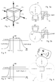
- Figure 4 illustrates a symmetrical realization of such a device that includes six electrodes disposed according to the faces of a cube, but other dispositions are possible.
- An estimate of the position of an approaching conductor body can be obtained from the capacities read by the electrodes.
- the electrode 20x+ for example, will respond more readily to the presence of conductor in the direction indicated as x+ while the opposite electrode 20x- will do the same for conductors in the direction indicated as x-. From these two signals, or from the average value and difference thereof, a position along the x-axis can be estimated.
- the pair 20y+/20y- that is aligned to the y-axis can provide an estimate of the y-position, and the pair 20z+/20z- an estimate of the z-position.
- At least two electrodes define one alignment axis and will suffice to determine directional proximity in one direction; the same determination in two dimensions will require at least two independent alignments, which can be obtained by three or preferably four electrodes; a full 3D application needs three independent alignment axis.
- FIGs 5a and 5b illustrate, in simplified and schematic fashion, a possible readout system for a multi-electrode arrangement: the capacitance seen by each electrode is measured in turn by a suitable readout circuit 80 while the other electrodes are held to ground or to a defined potential.
- This arrangement enhances the directivity of the measure: In figure 5a the electrode 20x+ is read, and the detection region 40 is essentially facing that electrode. In figure 5b , conversely, it is the capacity seen by electrode 20y- that is read, and the detection region is correspondingly displaced.
- the apparatus By reading all the electrodes, the position of an approaching body can be ascertained, or the apparatus can be programmed to detect objects in a predetermined detection region 40, rejecting those in predetermined rejection regions 42, as illustrated in figure 6 .
- the apparatus is included in a mobile phone and is arranged for detecting when the phone is brought to the ear.
- the readout circuit 80 represented in the drawings uses a floating AC voltage reference to read the capacitance between the connected electrode and ground whose principles of operation are described in the publication EP2876407 cited above. It must be understood however that this is not an essential feature of the invention, which could make use of any suitable capacity measuring circuit.
- XpDiff XnDiff
- YpDiff YnDiff
- ZpDiff ZnDiff
- ZnDiff ZnDiff
- a suitable calibration transformation is used to obtain the weighted values XpPond, XnPond, YpPond, YnPond, ZpPond, and ZnPond, from the raw values.
- XpPond CoefXpPond ⁇ Xpdiff
- XnPond CoefXnPond ⁇ Xndiff
- YpPond CoefYpPond ⁇ Ypdiff
- ZpPond CoefZpPond ⁇ Zpdiff
- ZnPond CoefZnPond ⁇ Zndiff
- a value Xmid 0 indicates that the object is essentially centred on the x-axis, whereas if Xmid ⁇ 0, the object is mostly on the negative side of the axis, and inversely for the opposite sign.
- a directional proximity indicator based on the values of Xmid, Ymid, Zmid can be obtained in several ways.
- YpDir YpPond 1 + Xatten + Yatten + Zatten and compared to a threshold to determine directive proximity.
- Figures 7 and 8 plot the values of YpDir dependent from Xmid.
- the dependence from Ymid and Zmid would be similar, and has not been plotted to avoid encumbering the figures.
- XmidLow respectively XmidHigh, denote the lower and upper thresholds of the directional proximity indicator YpDir, while the coefficient CoefXminLow and CoefXminHigh determine the steepness of the transition.
- Figures 9a and 9b illustrate a possible disposition of the proximity electrodes in a mobile phone.
- the application that is envisaged is that of dimming or switching off automatically the display when the telephone is close to the user head, for example during a phone call.
- a 2D discrimination is considered sufficient.
- the detector comprises a pair 201 202 of x-aligned electrodes and one single back electrode 200 behind the x-electrodes.
- the capacity of the combination 201/202 is used to detect proximity in the y+ direction, that is the direction of approach when the device is moved to the user's head, while the electrode 200 that blocks the detection in the y-direction, thus avoiding false positives from the user's hand holding the phone.
- the discrimination in the x direction is important to avoid false detection when the fingers of the user approach the upper edge of the phone or the top of the display 15.
- the back electrode 200 could provide a signal of directional proximity to objects approaching the device from the back. When this is not needed, it can be replaced with a static ground plane or shield 210, as shown in figure 9b .
- the electrodes 201, 202, and eventually 200 can be advantageously fabricated with flexible PCB techniques, but any kind of conductive electrode would be suitable.
- the size of the electrodes has a direct impact on the sensitivity and range of the sensor and, in most cases, they will cover all the available surface.
- a free margin 240 of some millimetre towards the edges, visible in figure 10 helps avoiding false detections when the device is gripped by the upper edge or the sides.
- the electrode can present discontinuities or holes, within reason, to allow the functioning of elements like the loudspeaker 55, an ambient light sensor 56, a camera objective 53, and a LED indicator 58.
- the PCB carrying the electrodes 201, 202 can also include traces relative to other signals and functions of the phone, although fast switching signal susceptible to interfere with the detection might dictate separation of layers and shielding with ground planes.
- Figure 11 illustrates a variant in which the x+ electrode 202 is larger than the x- electrode 201, and the latter is u-shaped with thin arms that run along the telephone sides.
- This arrangement offers several advantages: firstly the increased area of the electrode 202 helps rejecting signal due to a finger moving towards the top of the display 15. Moreover, the side arms of 201 electrode shield the electrode 202 from conductors in the z direction and help rejecting signals due, for example to fingers gripping the phone's sides.
- Figure 12 illustrates another structure in which the z-rejection is further improved by bringing two strips of the electrode 200 in front, for example through vias.
- figure 12 presents two regions 242 that could give rise to false detections.
- Figure 13 illustrates another implementation in which the "U" shape is applied to the electrode 202, to move the regions 242 upwards, far from the display.
- Figure 14 shows how the detection region 40 of the device can be adapted to specific applications by choosing the values of parameters XmidLow, XmidHigh, and also CoefXmidLow, CoefXmidHigh (see figure 7 ) and the detection thresholds. Decreasing XmidLow opens the ⁇ x - angle, while increasing XmidHigh opens the ⁇ x + angle.
- the detection region 40 is delimited by an angle ⁇ y- above the telephone.
- This disposition may be advantageous to detect when a user approaches the phone to the ear in an oblique fashion. It is implemented by setting a discrimination threshold to the signal YpDir.
- the angle ⁇ y- is determined by choosing the values YmidLow, CoefYmidLow opportunely. On the other hand the value CoefYmidHigh is set to zero, thus opening completely the detection region in the direction of increasing y.
- the electronic processing unit of the invention is arranged to generate a directional proximity signal based on the capacities seen by the electrodes, when the proximate body part is in a predefined geometric relation, for example in the directions comprised between angles ⁇ x- and ⁇ x +.
- the geometric relation required to trigger a proximity signal can be chosen dynamically by setting opportunely the parameters of the detection algorithm, XmidLow, XmidHigh for example.
- the variant of figure 15 shows how the system of the invention can be arranged in order to detect directional proximity of a body part, including in regions towards the back side (or the lateral sides should the need arise).
- the main detection threshold value 300 is set in consideration of the desired detection distance (the higher the threshold, the smaller the detection distance) and of the noise and disturbance levels. Preferably, an hysteresis is introduced to avoid erratic signals. Various debouncing algorithms can also be used, as it is known in the art.
Landscapes
- Engineering & Computer Science (AREA)
- Theoretical Computer Science (AREA)
- General Engineering & Computer Science (AREA)
- Physics & Mathematics (AREA)
- General Physics & Mathematics (AREA)
- Signal Processing (AREA)
- Human Computer Interaction (AREA)
- Computer Networks & Wireless Communication (AREA)
- Remote Sensing (AREA)
- Life Sciences & Earth Sciences (AREA)
- Telephone Function (AREA)
- Electromagnetism (AREA)
- Environmental & Geological Engineering (AREA)
- Geology (AREA)
- General Life Sciences & Earth Sciences (AREA)
- Geophysics (AREA)
- Switches That Are Operated By Magnetic Or Electric Fields (AREA)
- Telephone Set Structure (AREA)
- Geophysics And Detection Of Objects (AREA)
Abstract
Description
- The present invention concerns a proximity sensor and a method for detecting the proximity of a body portion. Embodiments of the present invention concern in particular portable devices like cell phones that, being equipped with the inventive sensor are capable of detecting the proximity of body parts and discriminate the direction whence the detected body part is approaching.
- It is often desired to detect whether a body portion is at short distance of an apparatus. In the particular case of cell phones and wirelessly connected mobile device, (including tablets and other similar terminals), this could be used to shut down the background lighting when the proximity of the user's head is detected, thus reducing the power consumption during calls.
- Avoiding false detection is, however, often important as well. In particular when the same or a different body portion approaches the apparatus from a different direction than the relevant one. In a cell phone, false detections may be due to the proximity of the fingers to the phone surface when handling it which, if detected as the presence of the head, will shut down the screen while the user is simply interacting with the phone.
- Sensors arranged for detecting a body near to an object, including inductive, optical, heat, and capacitive based sensors, are known. In the cell phone market, the most common method today is the infrared optical detection that has a good range and directivity. The main drawbacks of the optical system are its power consumption, the cost of its components and of its integration in the phone and the size needed to implement the solution on the phone surface.
- Capacitive sensors have a lower power consumption, require only a small area or no area on the phone surface and have a lower cost. They are however quite omnidirectional and therefore tends to generate lots of false positives, i.e. detection of body portions from irrelevant directions. This risk of false detection could be reduced by reducing severely the range of detection.
- An example of capacitive sensor for proximity sensing in a mobile communication device is described in
WO2013/079267 , whose content is hereby included by reference. This solution requires a device having a capacitive touch-sensitive area for touch input, which is not always available. Even when such a touch display is available, the signals that it generates may not be easily to access and/or process. - Another capacitive sensor is described in
US2010026656A , which also requires a touch panel. - European patent application
EP2876407 , in the name of the applicant describes capacitive sensors that are read by means of charge amplifiers connected to a floating variable voltage reference. The same document describes the use of such sensors in touch-sensitive displays. - It is therefore an aim of the invention to provide a method and sensor based on a capacitive sensor and which has an improved direction discrimination, in order to reduce the risk of false detection.
- Further, the present invention proposes a capacitive proximity device with an improved detection range.
- Another aim of the invention is providing a method and sensor which could be adapted to mobile devices having a touch panel, but also to those that lack such a panel, and a corresponding mobile device.
- It is another aim to provide a method and a sensor whose power consumption is far below that of infrared based systems.
- According to an aspect of the invention, these aims are achieved by the objects of the appended claims.
- The invention will be better understood with the aid of the description of an embodiment given by way of example and illustrated by the figures, in which:
-
Figure 1 illustrates a cut view of an example of a sensor according to the invention. -
Figure 2 illustrates a cut view of an example of a wireless phone including a proximity sensor according to the invention. -
Figure 3 illustrates a front view of a wireless phone including a sensor according to the invention. -
Figure 4 illustrates schematically a multi-electrode arrangement that provides 3D proximity discrimination. -
Figures 5a and 5b show a manner of reading the electrodes offigure 4 and the resulting sense lobes. -
Figure 6 illustrates how the 3D proximity discrimination can be used to detect when a mobile user is taken to the ear of a user. -
Figures 7 and 8 illustrate how the sensitivity lobes can be chosen. -
Figure 9a and 9b show schematically two possible manners of arranging the device of the invention in a mobile phone, viewed from the side and in section. -
Figures 10-13 are possible dispositions of the proximity electrodes in a mobile phone, viewed from the face. -
Figures 14 and 15 show schematically how the choice of the detection limit angles influences the sense zones. - An example of sensor is illustrated on
Figure 1 . It comprises one or a plurality of internalcapacitive electrodes first region 40, for example the region where presence of a body portion should trigger an action, such as shutting down a display or the illumination of a display. Aconductive shield 30 with lateral ground walls is arranged next to the centralinternal electrode 20, for example surrounding theinternal electrode 20, in order to reduce the sensibility of the internal capacitive electrode to proximity of objects in at least onesecond region 42, which might for example include all the available space except thefirst region 40. The shield may have an annular shape and, preferably, might further include abottom ground plate 31 below the internal electrode for preventing detection from the back. - At least one second external
capacitive electrode 22 is provided on the other side of the shield for detecting electrical charges, indicative of proximity with an object in one or a plurality of second regions different from the first region. In the presented example, theexternal electrode 22 comprises an annular plate around theconductive shield 31 which is also annular, such that theexternal electrode 22 surrounds theshield 30 which in turn surrounds thecentral electrode 20. This is not however the only possible disposition. This external electrode has a low sensibility to charges from the first direction which are shielded by the ground wall, thus it is relatively insensitive to charges in thedetection region 40, while it is highly responsive to charges in therejection region 42. - An electronic circuit (not shown) receives signals from the internal electrode and signals from the external electrode, and makes a weighted comparison to determine whether a detected charge comes mainly from the first region, mainly from the second region, or from both regions.
- The electronic circuit acquires signals from each individual directional electrode and apply a computation weighting the various electrodes to define the actual proximity in the desired region. A typical computation may be Position = CS2position - K * CS1position where K is set to reject signals coming from the region observed by CS1.
- To get more directional control several "negative" electrodes can be used and individually weighted in the computation. A plurality of grounded shields may also be used.
- The different electrodes are thus able to detect the proximity of a body portion from the top, from each side and from the bottom. With a specific algorithm, the electronics will be able to distinguish "positive" detection from "negative" detection (from other regions) and to generate a signal in order for example to shut down a display, or reduce its illumination, when a body portion is detected in the first region, or in the first region only.
-
Figure 2 illustrates an example ofcell phone 50 including such a proximity sensor. In this embodiment, theexternal electrode 22 is mounted below an annular portion 33 of theground shield 30, in order to reduce it sensitivity to charges in regions toward the front face of the phone as compared to charges from the back side. The internal electrode thus looks towards the screen surface side of the phone, while at least one external electrode looks toward the side and the bottom of the phone. -
Figure 3 illustrates a front view of awireless phone 50 including a sensor according to the invention. In this example, theinternal electrode 20 is provided on top of the front face of a mobile communication device, close to the loudspeaker. The groundedshield 22 is provided around the internal electrode, above the display 15 (here a LCD display). The external electrode might have an annular shape around the shield, for example above the display. - The disposition of electrodes of
figures 1 and 2 can be generalized to proximity sensor that enable various degrees of 2D or 3D discrimination. The detector of the invention may include a plurality of capacitive electrodes for detecting the proximity of a body portion in a first region while rejecting proximate body portions in a second region. An electronic processing circuit is arranged for reading the capacity seen by each of the electrodes and decide whether a body portion is present in said first region, but not in said second one. - In most cases, a pair of electrodes will be used for each measure axis, and therefore a 3D sensor could comprise six independent electrodes.
Figure 4 illustrates a symmetrical realization of such a device that includes six electrodes disposed according to the faces of a cube, but other dispositions are possible. - An estimate of the position of an approaching conductor body can be obtained from the capacities read by the electrodes. The electrode 20x+, for example, will respond more readily to the presence of conductor in the direction indicated as x+ while the
opposite electrode 20x- will do the same for conductors in the direction indicated as x-. From these two signals, or from the average value and difference thereof, a position along the x-axis can be estimated. Likewise, the pair 20y+/20y- that is aligned to the y-axis, can provide an estimate of the y-position, and the pair 20z+/20z- an estimate of the z-position. In most or all cases, at least two electrodes define one alignment axis and will suffice to determine directional proximity in one direction; the same determination in two dimensions will require at least two independent alignments, which can be obtained by three or preferably four electrodes; a full 3D application needs three independent alignment axis. -
Figures 5a and 5b illustrate, in simplified and schematic fashion, a possible readout system for a multi-electrode arrangement: the capacitance seen by each electrode is measured in turn by asuitable readout circuit 80 while the other electrodes are held to ground or to a defined potential. This arrangement enhances the directivity of the measure: Infigure 5a the electrode 20x+ is read, and thedetection region 40 is essentially facing that electrode. Infigure 5b , conversely, it is the capacity seen byelectrode 20y- that is read, and the detection region is correspondingly displaced. - By reading all the electrodes, the position of an approaching body can be ascertained, or the apparatus can be programmed to detect objects in a
predetermined detection region 40, rejecting those inpredetermined rejection regions 42, as illustrated infigure 6 . In this case the apparatus is included in a mobile phone and is arranged for detecting when the phone is brought to the ear. - The
readout circuit 80 represented in the drawings uses a floating AC voltage reference to read the capacitance between the connected electrode and ground whose principles of operation are described in the publicationEP2876407 cited above. It must be understood however that this is not an essential feature of the invention, which could make use of any suitable capacity measuring circuit. - Several algorithms for determining directive proximity weighting the capacity signals obtained by the electrodes are possible. According to one example, which has been successfully tested, the determination proceeds as follows:
- Initially the values of capacity seen by each sensor are read. Such values are often differential values and are termed XpDiff, XnDiff, YpDiff, YnDiff, ZpDiff, and ZnDiff, where the first letter designates the axis X, Y, or Z and the second the polarity, +/-. A suitable calibration transformation is used to obtain the weighted values XpPond, XnPond, YpPond, YnPond, ZpPond, and ZnPond, from the raw values.


where the transformation is, for this example, a linear homogeneous one. It must be understood, however that the calibration could be more complex and include offset terms as well as non-linear ones. The transformation allows, among other things, aligning the sensor response to the physical X/Y/Z axis. - Average position estimates Xmid, for the x-axis are obtained by:

and analogously for Ymid and Ymid. - A value Xmid = 0 indicates that the object is essentially centred on the x-axis, whereas if Xmid < 0, the object is mostly on the negative side of the axis, and inversely for the opposite sign.
- A directional proximity indicator based on the values of Xmid, Ymid, Zmid can be obtained in several ways. One valid possibility is computing the directional attenuation values Xatten, Yatten, Zatten follows:

and analogously for Yatten and Zatten. - Finally the quantity YpDir is computed

and compared to a threshold to determine directive proximity. -
Figures 7 and 8 plot the values of YpDir dependent from Xmid. The dependence from Ymid and Zmid would be similar, and has not been plotted to avoid encumbering the figures. XmidLow, respectively XmidHigh, denote the lower and upper thresholds of the directional proximity indicator YpDir, while the coefficient CoefXminLow and CoefXminHigh determine the steepness of the transition.Figure 8 shows the special case in which CoefXmidHigh = 0. In this case, the upper threshold is ineffective. -
Figures 9a and 9b illustrate a possible disposition of the proximity electrodes in a mobile phone. The application that is envisaged is that of dimming or switching off automatically the display when the telephone is close to the user head, for example during a phone call. In this example, a 2D discrimination is considered sufficient. Hence, the detector comprises apair 201 202 of x-aligned electrodes and onesingle back electrode 200 behind the x-electrodes. The capacity of thecombination 201/202 is used to detect proximity in the y+ direction, that is the direction of approach when the device is moved to the user's head, while theelectrode 200 that blocks the detection in the y-direction, thus avoiding false positives from the user's hand holding the phone. The discrimination in the x direction is important to avoid false detection when the fingers of the user approach the upper edge of the phone or the top of thedisplay 15. - The
back electrode 200 could provide a signal of directional proximity to objects approaching the device from the back. When this is not needed, it can be replaced with a static ground plane or shield 210, as shown infigure 9b . - The
electrodes free margin 240 of some millimetre towards the edges, visible infigure 10 , helps avoiding false detections when the device is gripped by the upper edge or the sides. The electrode can present discontinuities or holes, within reason, to allow the functioning of elements like theloudspeaker 55, an ambientlight sensor 56, acamera objective 53, and aLED indicator 58. - Optionally, and insofar as the sense area is not excessively reduced, the PCB carrying the
electrodes -
Figure 11 illustrates a variant in which thex+ electrode 202 is larger than the x-electrode 201, and the latter is u-shaped with thin arms that run along the telephone sides. This arrangement offers several advantages: firstly the increased area of theelectrode 202 helps rejecting signal due to a finger moving towards the top of thedisplay 15. Moreover, the side arms of 201 electrode shield theelectrode 202 from conductors in the z direction and help rejecting signals due, for example to fingers gripping the phone's sides. -
Figure 12 illustrates another structure in which the z-rejection is further improved by bringing two strips of theelectrode 200 in front, for example through vias. - The structure of
figure 12 presents tworegions 242 that could give rise to false detections.Figure 13 illustrates another implementation in which the "U" shape is applied to theelectrode 202, to move theregions 242 upwards, far from the display. These are however only some examples of the possible electrode's shape and, indeed, the invention can make use of electrodes of whichever shape needed to address specific applications. -
Figure 14 shows how thedetection region 40 of the device can be adapted to specific applications by choosing the values of parameters XmidLow, XmidHigh, and also CoefXmidLow, CoefXmidHigh (seefigure 7 ) and the detection thresholds. Decreasing XmidLow opens the αx- angle, while increasing XmidHigh opens the αx+ angle. - In another possible application represented in
figure 15 , thedetection region 40 is delimited by an angle αy- above the telephone. This disposition may be advantageous to detect when a user approaches the phone to the ear in an oblique fashion. It is implemented by setting a discrimination threshold to the signal YpDir. The angle αy- is determined by choosing the values YmidLow, CoefYmidLow opportunely. On the other hand the value CoefYmidHigh is set to zero, thus opening completely the detection region in the direction of increasing y. - The electronic processing unit of the invention is arranged to generate a directional proximity signal based on the capacities seen by the electrodes, when the proximate body part is in a predefined geometric relation, for example in the directions comprised between angles αx- and αx+. The geometric relation required to trigger a proximity signal can be chosen dynamically by setting opportunely the parameters of the detection algorithm, XmidLow, XmidHigh for example.
- The variant of
figure 15 shows how the system of the invention can be arranged in order to detect directional proximity of a body part, including in regions towards the back side (or the lateral sides should the need arise). - The main
detection threshold value 300 is set in consideration of the desired detection distance (the higher the threshold, the smaller the detection distance) and of the noise and disturbance levels. Preferably, an hysteresis is introduced to avoid erratic signals. Various debouncing algorithms can also be used, as it is known in the art. -
- 15
- display
- 20
- internal electrode
- 20x+, 20x-
- x-axis electrode pair
- 20y+, 20y-
- y-axis electrode pair
- 20z+, 20z-
- z-axis electrode pair
- 30
- shield
- 31
- bottom or annular plate
- 40
- detection region
- 42
- rejection region
- 50
- cell phone
- 53
- camera
- 55
- loudspeaker
- 56
- ambient light sensor
- 58
- notifications LED
- 80
- readout circuit
- 200
- back electrode
- 201
- front electrode
- 202
- front electrode
- 210
- ground plane
- 240
- margin
- 242
- false detection regions
- 310
- main threshold
Claims (12)
- A proximity sensor for detecting proximity of a body portion in a first region while avoiding unwanted detection of a body portion in a second region, comprising:a plurality of capacitive electrodes for detecting said body portion in respective detection regions ;an electronic circuit receiving signals from said capacitive electrodes, arranged for producing a directional proximity detection signal when said body portion is in said first region and not in said second region, based on the capacities seen by said capacitive electrodes.
- The proximity sensor of the preceding claim wherein said plurality of capacitive electrodes include:an internal capacitive electrode for detecting said body portion in the first region;an external capacitive electrode for detecting said body portion in the second region;a conductive shield for limiting the sensibility of the internal electrode to body portions in the second region and for limiting the sensibility of the external electrode to body portions in the first region,and the electronic circuit is arranged for producing a detection signal when a body portion is in the first region but not when a body portion is in the second region.
- The apparatus of claim 2, the shield comprising at least one lateral wall portion around the internal electrode.
- The apparatus of claim 3, the shield comprising at least one bottom wall portion under the internal capacitive electrode.
- The apparatus of one of the claims 2 to 4, the external capacitive electrode having an annular shape.
- The apparatus of one of the claims 2 to 5, comprising a plurality of said external capacitive electrodes.
- The apparatus of any one of the preceding claims 2 to 6, said electronic circuit being arranged for weighting said signals.
- A cell phone comprising:a sensor according to any one of the preceding claims;a display;means to reduce the power consumption of said phone,whereby the electronic circuit, is arranged to reduce the power consumption when the sensor detects a body in predefined relation of directional proximity.
- The cell phone of claim 8, comprising a front face with a display and a loudspeaker,
the internal capacitive electrode being arranged on said front face to detect said body portion in said first region close to said loudspeaker. - The cell phone of claim 8, the surface of the internal capacitive electrode being smaller than the surface of said display.
- The cell phone of any one of claims 8 to 10, said capacitive electrodes being arranged above said display.
- The cell phone of any one of claims 8 to 11, comprising lateral sides and a back side,
said capacitive electrodes being arranged for detecting body portions in a plurality of regions including regions toward said lateral sides and toward said back side.
Applications Claiming Priority (1)
| Application Number | Priority Date | Filing Date | Title |
|---|---|---|---|
| US201462039240P | 2014-08-19 | 2014-08-19 |
Publications (2)
| Publication Number | Publication Date |
|---|---|
| EP2988479A1 true EP2988479A1 (en) | 2016-02-24 |
| EP2988479B1 EP2988479B1 (en) | 2019-01-30 |
Family
ID=53835348
Family Applications (1)
| Application Number | Title | Priority Date | Filing Date |
|---|---|---|---|
| EP15180782.3A Active EP2988479B1 (en) | 2014-08-19 | 2015-08-12 | Capacitive proximity sensor and mobile device |
Country Status (4)
| Country | Link |
|---|---|
| US (1) | US9794748B2 (en) |
| EP (1) | EP2988479B1 (en) |
| KR (2) | KR101983008B1 (en) |
| CN (2) | CN105892775B (en) |
Cited By (7)
| Publication number | Priority date | Publication date | Assignee | Title |
|---|---|---|---|---|
| CN106210294A (en) * | 2016-06-30 | 2016-12-07 | 北京小米移动软件有限公司 | Screen state method for handover control and device |
| EP3293953A1 (en) | 2016-09-07 | 2018-03-14 | Semtech Corporation | Capacitive proximity sensor in a mobile device and method of limiting radiation absorption |
| CN108965583A (en) * | 2018-06-15 | 2018-12-07 | Oppo广东移动通信有限公司 | Proximity detection method and related equipment |
| EP3422577A1 (en) | 2017-06-27 | 2019-01-02 | Semtech Corporation | Capacitive proximity sensor |
| EP3595175A1 (en) | 2018-07-09 | 2020-01-15 | Semtech Corporation | Proximity sensor and mobile wireless device |
| EP3595176A1 (en) | 2018-07-13 | 2020-01-15 | Semtech Corporation | Intelligent proximity detector |
| US12107575B2 (en) | 2021-09-29 | 2024-10-01 | Semtech Corporation | Environmental sensor circuit having a capacitive proximity sensor and magnetic field probe |
Families Citing this family (16)
| Publication number | Priority date | Publication date | Assignee | Title |
|---|---|---|---|---|
| WO2017199550A1 (en) * | 2016-05-17 | 2017-11-23 | シャープ株式会社 | Proximity sensor, proximity illumination intensity sensor, electronic device, and proximity sensor calibration method |
| US10502548B2 (en) | 2017-05-09 | 2019-12-10 | Google Llc | Sensor combination |
| EP3402073B1 (en) * | 2017-05-12 | 2021-02-03 | Semtech Corporation | Drift suppression filter proximity detector and method |
| EP3404835B1 (en) | 2017-05-16 | 2020-09-09 | Semtech Corporation | Single sensor proximity detector |
| CN107102864A (en) * | 2017-05-16 | 2017-08-29 | 广东欧珀移动通信有限公司 | One kind puts out screen control method, device, storage medium and terminal |
| CN111357165A (en) | 2017-09-18 | 2020-06-30 | Sem技术公司 | System and method for wireless power transfer and communication |
| KR102426351B1 (en) | 2017-09-29 | 2022-07-29 | 삼성전자주식회사 | Electronic device for grip sensing and method for operating thereof |
| KR102460507B1 (en) | 2017-11-03 | 2022-10-28 | 삼성전자 주식회사 | Method and electronic device for calibrating sensing value of sensor of the same |
| KR102464610B1 (en) * | 2017-11-20 | 2022-11-08 | 현대자동차주식회사 | Proximity sensor |
| CN108572767B (en) * | 2018-03-20 | 2020-02-21 | 维沃移动通信有限公司 | A method for determining the orientation of an external object, and a mobile terminal |
| CN109088978B (en) * | 2018-06-27 | 2021-03-16 | 维沃移动通信有限公司 | Terminal and method for controlling terminal |
| CN112671956B (en) * | 2019-10-16 | 2023-06-30 | 北京小米移动软件有限公司 | Human body distance detection module of electronic equipment, electronic equipment and control method thereof |
| CN112751998B (en) * | 2019-10-31 | 2023-02-28 | 珠海市魅族科技有限公司 | Terminal equipment, distance sensing processing method and device thereof and storage medium |
| KR102340401B1 (en) * | 2019-12-23 | 2021-12-20 | 황성공업 주식회사 | Object sensing apparatus, method and recorded media for performing same |
| CN111585560B (en) * | 2020-04-27 | 2023-08-11 | 北京他山科技有限公司 | A kind of non-contact keyboard capacitive sensor and input method |
| US11263888B1 (en) | 2020-09-30 | 2022-03-01 | HCL Technologies Italy S.p.A. | Multiple proximity sensors based electronic device |
Citations (6)
| Publication number | Priority date | Publication date | Assignee | Title |
|---|---|---|---|---|
| US20050001633A1 (en) * | 2003-05-14 | 2005-01-06 | Akihiro Okushima | Object detection sensor |
| US20060250142A1 (en) * | 2002-12-25 | 2006-11-09 | Hiroshi Abe | Electrostatic capacity detection type proximity sensor |
| US20100026656A1 (en) | 2008-07-31 | 2010-02-04 | Apple Inc. | Capacitive sensor behind black mask |
| US20120280698A1 (en) * | 2010-01-13 | 2012-11-08 | Junichiro Oya | Capacitance-type proximity sensor device and electronic apparatus using the same |
| WO2013079267A1 (en) | 2011-11-28 | 2013-06-06 | Sony Mobile Communications Ab | Capacitive proximity sensing in a handheld device |
| EP2876407A1 (en) | 2013-11-26 | 2015-05-27 | Semtech Corporation | Capacitive sensing interface for proximity detection |
Family Cites Families (16)
| Publication number | Priority date | Publication date | Assignee | Title |
|---|---|---|---|---|
| US7728316B2 (en) * | 2005-09-30 | 2010-06-01 | Apple Inc. | Integrated proximity sensor and light sensor |
| JP4645989B2 (en) * | 2006-06-30 | 2011-03-09 | Toto株式会社 | Capacitive proximity sensor and hot water cleaning toilet seat device and bathtub device equipped with the same |
| US8669944B2 (en) * | 2008-12-15 | 2014-03-11 | Sony Corporation | Touch sensitive displays with layers of sensor plates providing capacitance based proximity sensing and related touch panels |
| US8902191B2 (en) * | 2009-01-28 | 2014-12-02 | Synaptics Incorporated | Proximity sensing for capacitive touch sensors |
| US8115499B2 (en) * | 2009-05-22 | 2012-02-14 | Freescale Semiconductor, Inc. | Device with proximity detection capability |
| JP2012528372A (en) * | 2009-05-27 | 2012-11-12 | コーニンクレッカ フィリップス エレクトロニクス エヌ ヴィ | Touch or proximity detection interface |
| US8432322B2 (en) * | 2009-07-17 | 2013-04-30 | Apple Inc. | Electronic devices with capacitive proximity sensors for proximity-based radio-frequency power control |
| US9189093B2 (en) * | 2010-02-10 | 2015-11-17 | Microchip Technology Germany Gmbh | System and method for the generation of a signal correlated with a manual input operation |
| JP2011232038A (en) * | 2010-04-23 | 2011-11-17 | Alps Electric Co Ltd | Capacitance type proximity sensor apparatus |
| DE102011003734B3 (en) * | 2011-02-07 | 2012-06-14 | Ident Technology Ag | Electrode configuration for a capacitive sensor device and capacitive sensor device for approach detection |
| KR101925485B1 (en) * | 2012-06-15 | 2019-02-27 | 삼성전자주식회사 | Apparatus and method for proximity touch sensing |
| US9176597B2 (en) * | 2012-07-02 | 2015-11-03 | Stmicroelectronics Asia Pacific Pte Ltd | Directional capacitive proximity sensor with bootstrapping |
| GB2504291A (en) * | 2012-07-24 | 2014-01-29 | St Microelectronics Ltd | A proximity and gesture detection module |
| US20140092053A1 (en) * | 2012-10-01 | 2014-04-03 | Stmicroelectronics Asia Pacific Pte Ltd | Information display orientation control using proximity detection |
| KR102020311B1 (en) * | 2013-01-22 | 2019-09-10 | 엘지전자 주식회사 | Method and terminal for recognizing jesture using muti-channel electrodes approach sensor |
| EP2948825A4 (en) * | 2013-01-23 | 2016-09-14 | Nokia Technologies Oy | METHOD AND APPARATUS FOR LIMITING A DETECTION REGION OF A CAPACITIVE DETECTION ELECTRODE |
-
2015
- 2015-08-12 EP EP15180782.3A patent/EP2988479B1/en active Active
- 2015-08-12 US US14/824,294 patent/US9794748B2/en active Active
- 2015-08-17 KR KR1020150115297A patent/KR101983008B1/en active Active
- 2015-08-19 CN CN201510511048.3A patent/CN105892775B/en active Active
- 2015-08-19 CN CN202110936660.0A patent/CN113655918A/en active Pending
-
2019
- 2019-05-17 KR KR1020190057730A patent/KR102159934B1/en active Active
Patent Citations (6)
| Publication number | Priority date | Publication date | Assignee | Title |
|---|---|---|---|---|
| US20060250142A1 (en) * | 2002-12-25 | 2006-11-09 | Hiroshi Abe | Electrostatic capacity detection type proximity sensor |
| US20050001633A1 (en) * | 2003-05-14 | 2005-01-06 | Akihiro Okushima | Object detection sensor |
| US20100026656A1 (en) | 2008-07-31 | 2010-02-04 | Apple Inc. | Capacitive sensor behind black mask |
| US20120280698A1 (en) * | 2010-01-13 | 2012-11-08 | Junichiro Oya | Capacitance-type proximity sensor device and electronic apparatus using the same |
| WO2013079267A1 (en) | 2011-11-28 | 2013-06-06 | Sony Mobile Communications Ab | Capacitive proximity sensing in a handheld device |
| EP2876407A1 (en) | 2013-11-26 | 2015-05-27 | Semtech Corporation | Capacitive sensing interface for proximity detection |
Cited By (15)
| Publication number | Priority date | Publication date | Assignee | Title |
|---|---|---|---|---|
| CN106210294B (en) * | 2016-06-30 | 2019-10-25 | 北京小米移动软件有限公司 | Screen state switching control method and device |
| CN106210294A (en) * | 2016-06-30 | 2016-12-07 | 北京小米移动软件有限公司 | Screen state method for handover control and device |
| US10027785B2 (en) | 2016-06-30 | 2018-07-17 | Beijing Xiaomi Mobile Software Co., Ltd. | Method for switching screen state of terminal, terminal thereof, and computer-readable medium thereof |
| EP3264130A1 (en) * | 2016-06-30 | 2018-01-03 | Beijing Xiaomi Mobile Software Co., Ltd. | Method and apparatus for screen state switching control |
| EP3293953A1 (en) | 2016-09-07 | 2018-03-14 | Semtech Corporation | Capacitive proximity sensor in a mobile device and method of limiting radiation absorption |
| US10879896B2 (en) | 2016-09-07 | 2020-12-29 | Semtech Corporation | Capacitive proximity sensor in a mobile device and method of limiting radiation absorption |
| US11128298B2 (en) | 2017-06-27 | 2021-09-21 | Semtech Corporation | Advanced capacitive proximity sensor |
| EP3422577A1 (en) | 2017-06-27 | 2019-01-02 | Semtech Corporation | Capacitive proximity sensor |
| CN108965583A (en) * | 2018-06-15 | 2018-12-07 | Oppo广东移动通信有限公司 | Proximity detection method and related equipment |
| EP3595175A1 (en) | 2018-07-09 | 2020-01-15 | Semtech Corporation | Proximity sensor and mobile wireless device |
| US11082550B2 (en) | 2018-07-09 | 2021-08-03 | Semtech Corporation | Proximity sensor and mobile wireless device |
| KR20200007730A (en) * | 2018-07-13 | 2020-01-22 | 셈테크 코포레이션 | Intelligent proximity detector |
| EP3595176A1 (en) | 2018-07-13 | 2020-01-15 | Semtech Corporation | Intelligent proximity detector |
| US11237613B2 (en) | 2018-07-13 | 2022-02-01 | Semtech Corporation | Intelligent proximity detector |
| US12107575B2 (en) | 2021-09-29 | 2024-10-01 | Semtech Corporation | Environmental sensor circuit having a capacitive proximity sensor and magnetic field probe |
Also Published As
| Publication number | Publication date |
|---|---|
| CN105892775B (en) | 2021-08-17 |
| US9794748B2 (en) | 2017-10-17 |
| EP2988479B1 (en) | 2019-01-30 |
| KR20190057233A (en) | 2019-05-28 |
| KR102159934B1 (en) | 2020-09-29 |
| CN113655918A (en) | 2021-11-16 |
| CN105892775A (en) | 2016-08-24 |
| KR20160022265A (en) | 2016-02-29 |
| US20160057578A1 (en) | 2016-02-25 |
| KR101983008B1 (en) | 2019-05-29 |
Similar Documents
| Publication | Publication Date | Title |
|---|---|---|
| EP2988479B1 (en) | Capacitive proximity sensor and mobile device | |
| KR102028783B1 (en) | Device for capacitive detection with arrangement of linking tracks, and method implementing such a device | |
| US11075633B2 (en) | Water-rejection proximity detector and method | |
| US20200409491A1 (en) | Passive Touch Detection for Capacitive Sense Array | |
| KR101858634B1 (en) | Sensing system using hall sensor and apparatus using thereof | |
| WO2012027088A2 (en) | Concurrent signal detection for touch and hover sensing | |
| EP3422577B1 (en) | Capacitive proximity sensor | |
| WO2010045067A2 (en) | Sensor device and method with at surface object sensing and away from surface object sensing | |
| US9141224B1 (en) | Shielding capacitive touch display | |
| JP2012515990A (en) | Conductive multi-touch touch panel | |
| CN110719348A (en) | Intelligent proximity detector | |
| JP2020515981A (en) | Water rejection on capacitive door handle | |
| US20090315570A1 (en) | Capacitive sensing device | |
| EP2630559B1 (en) | Mobile communication device with three-dimensional sensing and a method therefore | |
| US11057036B2 (en) | Switching operation sensing device that distinguishes touch regions on surface of integrated housing | |
| US9081452B2 (en) | Method, apparatus and computer program for enabling registration of user actuations | |
| CN107968855B (en) | Electronic device, electronic equipment and display control method | |
| JP6739193B2 (en) | Touch panel | |
| US9255781B2 (en) | Method and system for determining proximity of an object | |
| US20160202796A1 (en) | Method for characterizing an object of interest by interacting with a measuring interface, and device implementing the method | |
| KR20230173601A (en) | Proximity sensor and antenna | |
| KR20150014585A (en) | Electric field sensor using change of electric field |
Legal Events
| Date | Code | Title | Description |
|---|---|---|---|
| PUAI | Public reference made under article 153(3) epc to a published international application that has entered the european phase |
Free format text: ORIGINAL CODE: 0009012 |
|
| AK | Designated contracting states |
Kind code of ref document: A1 Designated state(s): AL AT BE BG CH CY CZ DE DK EE ES FI FR GB GR HR HU IE IS IT LI LT LU LV MC MK MT NL NO PL PT RO RS SE SI SK SM TR |
|
| AX | Request for extension of the european patent |
Extension state: BA ME |
|
| 17P | Request for examination filed |
Effective date: 20160815 |
|
| RBV | Designated contracting states (corrected) |
Designated state(s): AL AT BE BG CH CY CZ DE DK EE ES FI FR GB GR HR HU IE IS IT LI LT LU LV MC MK MT NL NO PL PT RO RS SE SI SK SM TR |
|
| STAA | Information on the status of an ep patent application or granted ep patent |
Free format text: STATUS: EXAMINATION IS IN PROGRESS |
|
| 17Q | First examination report despatched |
Effective date: 20171212 |
|
| RIC1 | Information provided on ipc code assigned before grant |
Ipc: H03K 17/96 20060101ALN20180803BHEP Ipc: G06F 3/044 20060101ALI20180803BHEP Ipc: G06F 1/32 20060101ALI20180803BHEP Ipc: G06F 3/01 20060101ALI20180803BHEP Ipc: G01B 7/14 20060101ALI20180803BHEP Ipc: H04M 1/02 20060101AFI20180803BHEP Ipc: H04W 4/02 20090101ALI20180803BHEP Ipc: H03K 17/955 20060101ALI20180803BHEP |
|
| GRAP | Despatch of communication of intention to grant a patent |
Free format text: ORIGINAL CODE: EPIDOSNIGR1 |
|
| STAA | Information on the status of an ep patent application or granted ep patent |
Free format text: STATUS: GRANT OF PATENT IS INTENDED |
|
| RIC1 | Information provided on ipc code assigned before grant |
Ipc: G06F 3/01 20060101ALI20180823BHEP Ipc: G01B 7/14 20060101ALI20180823BHEP Ipc: H04W 4/02 20090101ALI20180823BHEP Ipc: H03K 17/955 20060101ALI20180823BHEP Ipc: H03K 17/96 20060101ALN20180823BHEP Ipc: G06F 1/32 20060101ALI20180823BHEP Ipc: H04M 1/02 20060101AFI20180823BHEP Ipc: G06F 3/044 20060101ALI20180823BHEP |
|
| INTG | Intention to grant announced |
Effective date: 20180914 |
|
| GRAS | Grant fee paid |
Free format text: ORIGINAL CODE: EPIDOSNIGR3 |
|
| GRAA | (expected) grant |
Free format text: ORIGINAL CODE: 0009210 |
|
| STAA | Information on the status of an ep patent application or granted ep patent |
Free format text: STATUS: THE PATENT HAS BEEN GRANTED |
|
| AK | Designated contracting states |
Kind code of ref document: B1 Designated state(s): AL AT BE BG CH CY CZ DE DK EE ES FI FR GB GR HR HU IE IS IT LI LT LU LV MC MK MT NL NO PL PT RO RS SE SI SK SM TR |
|
| REG | Reference to a national code |
Ref country code: GB Ref legal event code: FG4D |
|
| REG | Reference to a national code |
Ref country code: CH Ref legal event code: EP |
|
| REG | Reference to a national code |
Ref country code: AT Ref legal event code: REF Ref document number: 1094156 Country of ref document: AT Kind code of ref document: T Effective date: 20190215 |
|
| REG | Reference to a national code |
Ref country code: IE Ref legal event code: FG4D |
|
| REG | Reference to a national code |
Ref country code: DE Ref legal event code: R096 Ref document number: 602015023906 Country of ref document: DE |
|
| REG | Reference to a national code |
Ref country code: LT Ref legal event code: MG4D |
|
| REG | Reference to a national code |
Ref country code: NL Ref legal event code: MP Effective date: 20190130 |
|
| PG25 | Lapsed in a contracting state [announced via postgrant information from national office to epo] |
Ref country code: PT Free format text: LAPSE BECAUSE OF FAILURE TO SUBMIT A TRANSLATION OF THE DESCRIPTION OR TO PAY THE FEE WITHIN THE PRESCRIBED TIME-LIMIT Effective date: 20190530 Ref country code: SE Free format text: LAPSE BECAUSE OF FAILURE TO SUBMIT A TRANSLATION OF THE DESCRIPTION OR TO PAY THE FEE WITHIN THE PRESCRIBED TIME-LIMIT Effective date: 20190130 Ref country code: FI Free format text: LAPSE BECAUSE OF FAILURE TO SUBMIT A TRANSLATION OF THE DESCRIPTION OR TO PAY THE FEE WITHIN THE PRESCRIBED TIME-LIMIT Effective date: 20190130 Ref country code: NO Free format text: LAPSE BECAUSE OF FAILURE TO SUBMIT A TRANSLATION OF THE DESCRIPTION OR TO PAY THE FEE WITHIN THE PRESCRIBED TIME-LIMIT Effective date: 20190430 Ref country code: PL Free format text: LAPSE BECAUSE OF FAILURE TO SUBMIT A TRANSLATION OF THE DESCRIPTION OR TO PAY THE FEE WITHIN THE PRESCRIBED TIME-LIMIT Effective date: 20190130 Ref country code: NL Free format text: LAPSE BECAUSE OF FAILURE TO SUBMIT A TRANSLATION OF THE DESCRIPTION OR TO PAY THE FEE WITHIN THE PRESCRIBED TIME-LIMIT Effective date: 20190130 Ref country code: ES Free format text: LAPSE BECAUSE OF FAILURE TO SUBMIT A TRANSLATION OF THE DESCRIPTION OR TO PAY THE FEE WITHIN THE PRESCRIBED TIME-LIMIT Effective date: 20190130 Ref country code: LT Free format text: LAPSE BECAUSE OF FAILURE TO SUBMIT A TRANSLATION OF THE DESCRIPTION OR TO PAY THE FEE WITHIN THE PRESCRIBED TIME-LIMIT Effective date: 20190130 |
|
| REG | Reference to a national code |
Ref country code: AT Ref legal event code: MK05 Ref document number: 1094156 Country of ref document: AT Kind code of ref document: T Effective date: 20190130 |
|
| PG25 | Lapsed in a contracting state [announced via postgrant information from national office to epo] |
Ref country code: IS Free format text: LAPSE BECAUSE OF FAILURE TO SUBMIT A TRANSLATION OF THE DESCRIPTION OR TO PAY THE FEE WITHIN THE PRESCRIBED TIME-LIMIT Effective date: 20190530 Ref country code: HR Free format text: LAPSE BECAUSE OF FAILURE TO SUBMIT A TRANSLATION OF THE DESCRIPTION OR TO PAY THE FEE WITHIN THE PRESCRIBED TIME-LIMIT Effective date: 20190130 Ref country code: GR Free format text: LAPSE BECAUSE OF FAILURE TO SUBMIT A TRANSLATION OF THE DESCRIPTION OR TO PAY THE FEE WITHIN THE PRESCRIBED TIME-LIMIT Effective date: 20190501 Ref country code: LV Free format text: LAPSE BECAUSE OF FAILURE TO SUBMIT A TRANSLATION OF THE DESCRIPTION OR TO PAY THE FEE WITHIN THE PRESCRIBED TIME-LIMIT Effective date: 20190130 Ref country code: BG Free format text: LAPSE BECAUSE OF FAILURE TO SUBMIT A TRANSLATION OF THE DESCRIPTION OR TO PAY THE FEE WITHIN THE PRESCRIBED TIME-LIMIT Effective date: 20190430 Ref country code: RS Free format text: LAPSE BECAUSE OF FAILURE TO SUBMIT A TRANSLATION OF THE DESCRIPTION OR TO PAY THE FEE WITHIN THE PRESCRIBED TIME-LIMIT Effective date: 20190130 |
|
| PG25 | Lapsed in a contracting state [announced via postgrant information from national office to epo] |
Ref country code: CZ Free format text: LAPSE BECAUSE OF FAILURE TO SUBMIT A TRANSLATION OF THE DESCRIPTION OR TO PAY THE FEE WITHIN THE PRESCRIBED TIME-LIMIT Effective date: 20190130 Ref country code: RO Free format text: LAPSE BECAUSE OF FAILURE TO SUBMIT A TRANSLATION OF THE DESCRIPTION OR TO PAY THE FEE WITHIN THE PRESCRIBED TIME-LIMIT Effective date: 20190130 Ref country code: IT Free format text: LAPSE BECAUSE OF FAILURE TO SUBMIT A TRANSLATION OF THE DESCRIPTION OR TO PAY THE FEE WITHIN THE PRESCRIBED TIME-LIMIT Effective date: 20190130 Ref country code: EE Free format text: LAPSE BECAUSE OF FAILURE TO SUBMIT A TRANSLATION OF THE DESCRIPTION OR TO PAY THE FEE WITHIN THE PRESCRIBED TIME-LIMIT Effective date: 20190130 Ref country code: DK Free format text: LAPSE BECAUSE OF FAILURE TO SUBMIT A TRANSLATION OF THE DESCRIPTION OR TO PAY THE FEE WITHIN THE PRESCRIBED TIME-LIMIT Effective date: 20190130 Ref country code: AL Free format text: LAPSE BECAUSE OF FAILURE TO SUBMIT A TRANSLATION OF THE DESCRIPTION OR TO PAY THE FEE WITHIN THE PRESCRIBED TIME-LIMIT Effective date: 20190130 Ref country code: SK Free format text: LAPSE BECAUSE OF FAILURE TO SUBMIT A TRANSLATION OF THE DESCRIPTION OR TO PAY THE FEE WITHIN THE PRESCRIBED TIME-LIMIT Effective date: 20190130 |
|
| REG | Reference to a national code |
Ref country code: DE Ref legal event code: R097 Ref document number: 602015023906 Country of ref document: DE |
|
| PG25 | Lapsed in a contracting state [announced via postgrant information from national office to epo] |
Ref country code: SM Free format text: LAPSE BECAUSE OF FAILURE TO SUBMIT A TRANSLATION OF THE DESCRIPTION OR TO PAY THE FEE WITHIN THE PRESCRIBED TIME-LIMIT Effective date: 20190130 |
|
| PLBE | No opposition filed within time limit |
Free format text: ORIGINAL CODE: 0009261 |
|
| STAA | Information on the status of an ep patent application or granted ep patent |
Free format text: STATUS: NO OPPOSITION FILED WITHIN TIME LIMIT |
|
| PG25 | Lapsed in a contracting state [announced via postgrant information from national office to epo] |
Ref country code: AT Free format text: LAPSE BECAUSE OF FAILURE TO SUBMIT A TRANSLATION OF THE DESCRIPTION OR TO PAY THE FEE WITHIN THE PRESCRIBED TIME-LIMIT Effective date: 20190130 |
|
| 26N | No opposition filed |
Effective date: 20191031 |
|
| PG25 | Lapsed in a contracting state [announced via postgrant information from national office to epo] |
Ref country code: SI Free format text: LAPSE BECAUSE OF FAILURE TO SUBMIT A TRANSLATION OF THE DESCRIPTION OR TO PAY THE FEE WITHIN THE PRESCRIBED TIME-LIMIT Effective date: 20190130 |
|
| PG25 | Lapsed in a contracting state [announced via postgrant information from national office to epo] |
Ref country code: TR Free format text: LAPSE BECAUSE OF FAILURE TO SUBMIT A TRANSLATION OF THE DESCRIPTION OR TO PAY THE FEE WITHIN THE PRESCRIBED TIME-LIMIT Effective date: 20190130 |
|
| PG25 | Lapsed in a contracting state [announced via postgrant information from national office to epo] |
Ref country code: LU Free format text: LAPSE BECAUSE OF NON-PAYMENT OF DUE FEES Effective date: 20190812 Ref country code: CH Free format text: LAPSE BECAUSE OF NON-PAYMENT OF DUE FEES Effective date: 20190831 Ref country code: MC Free format text: LAPSE BECAUSE OF FAILURE TO SUBMIT A TRANSLATION OF THE DESCRIPTION OR TO PAY THE FEE WITHIN THE PRESCRIBED TIME-LIMIT Effective date: 20190130 Ref country code: LI Free format text: LAPSE BECAUSE OF NON-PAYMENT OF DUE FEES Effective date: 20190831 |
|
| REG | Reference to a national code |
Ref country code: BE Ref legal event code: MM Effective date: 20190831 |
|
| PG25 | Lapsed in a contracting state [announced via postgrant information from national office to epo] |
Ref country code: IE Free format text: LAPSE BECAUSE OF NON-PAYMENT OF DUE FEES Effective date: 20190812 |
|
| PG25 | Lapsed in a contracting state [announced via postgrant information from national office to epo] |
Ref country code: BE Free format text: LAPSE BECAUSE OF NON-PAYMENT OF DUE FEES Effective date: 20190831 |
|
| PG25 | Lapsed in a contracting state [announced via postgrant information from national office to epo] |
Ref country code: CY Free format text: LAPSE BECAUSE OF FAILURE TO SUBMIT A TRANSLATION OF THE DESCRIPTION OR TO PAY THE FEE WITHIN THE PRESCRIBED TIME-LIMIT Effective date: 20190130 |
|
| PG25 | Lapsed in a contracting state [announced via postgrant information from national office to epo] |
Ref country code: HU Free format text: LAPSE BECAUSE OF FAILURE TO SUBMIT A TRANSLATION OF THE DESCRIPTION OR TO PAY THE FEE WITHIN THE PRESCRIBED TIME-LIMIT; INVALID AB INITIO Effective date: 20150812 Ref country code: MT Free format text: LAPSE BECAUSE OF FAILURE TO SUBMIT A TRANSLATION OF THE DESCRIPTION OR TO PAY THE FEE WITHIN THE PRESCRIBED TIME-LIMIT Effective date: 20190130 |
|
| PG25 | Lapsed in a contracting state [announced via postgrant information from national office to epo] |
Ref country code: MK Free format text: LAPSE BECAUSE OF FAILURE TO SUBMIT A TRANSLATION OF THE DESCRIPTION OR TO PAY THE FEE WITHIN THE PRESCRIBED TIME-LIMIT Effective date: 20190130 |
|
| P01 | Opt-out of the competence of the unified patent court (upc) registered |
Effective date: 20230530 |
|
| PGFP | Annual fee paid to national office [announced via postgrant information from national office to epo] |
Ref country code: DE Payment date: 20250827 Year of fee payment: 11 |
|
| PGFP | Annual fee paid to national office [announced via postgrant information from national office to epo] |
Ref country code: GB Payment date: 20250827 Year of fee payment: 11 |
|
| PGFP | Annual fee paid to national office [announced via postgrant information from national office to epo] |
Ref country code: FR Payment date: 20250825 Year of fee payment: 11 |