EP2988430B1 - Verfahren zur bestimmung eines vorcodierungsmatrixindikators, benutzervorrichtung und basisstation - Google Patents
Verfahren zur bestimmung eines vorcodierungsmatrixindikators, benutzervorrichtung und basisstation Download PDFInfo
- Publication number
- EP2988430B1 EP2988430B1 EP13883972.5A EP13883972A EP2988430B1 EP 2988430 B1 EP2988430 B1 EP 2988430B1 EP 13883972 A EP13883972 A EP 13883972A EP 2988430 B1 EP2988430 B1 EP 2988430B1
- Authority
- EP
- European Patent Office
- Prior art keywords
- matrix
- user equipment
- reference signal
- specific
- subset
- Prior art date
- Legal status (The legal status is an assumption and is not a legal conclusion. Google has not performed a legal analysis and makes no representation as to the accuracy of the status listed.)
- Active
Links
Images

Classifications
-
- H—ELECTRICITY
- H04—ELECTRIC COMMUNICATION TECHNIQUE
- H04B—TRANSMISSION
- H04B7/00—Radio transmission systems, i.e. using radiation field
- H04B7/02—Diversity systems; Multi-antenna system, i.e. transmission or reception using multiple antennas
- H04B7/04—Diversity systems; Multi-antenna system, i.e. transmission or reception using multiple antennas using two or more spaced independent antennas
- H04B7/0413—MIMO systems
- H04B7/0456—Selection of precoding matrices or codebooks, e.g. using matrices antenna weighting
-
- H—ELECTRICITY
- H04—ELECTRIC COMMUNICATION TECHNIQUE
- H04B—TRANSMISSION
- H04B7/00—Radio transmission systems, i.e. using radiation field
- H04B7/02—Diversity systems; Multi-antenna system, i.e. transmission or reception using multiple antennas
- H04B7/04—Diversity systems; Multi-antenna system, i.e. transmission or reception using multiple antennas using two or more spaced independent antennas
- H04B7/06—Diversity systems; Multi-antenna system, i.e. transmission or reception using multiple antennas using two or more spaced independent antennas at the transmitting station
- H04B7/0613—Diversity systems; Multi-antenna system, i.e. transmission or reception using multiple antennas using two or more spaced independent antennas at the transmitting station using simultaneous transmission
- H04B7/0615—Diversity systems; Multi-antenna system, i.e. transmission or reception using multiple antennas using two or more spaced independent antennas at the transmitting station using simultaneous transmission of weighted versions of same signal
- H04B7/0619—Diversity systems; Multi-antenna system, i.e. transmission or reception using multiple antennas using two or more spaced independent antennas at the transmitting station using simultaneous transmission of weighted versions of same signal using feedback from receiving side
- H04B7/0636—Feedback format
- H04B7/0639—Using selective indices, e.g. of a codebook, e.g. pre-distortion matrix index [PMI] or for beam selection
-
- H—ELECTRICITY
- H04—ELECTRIC COMMUNICATION TECHNIQUE
- H04B—TRANSMISSION
- H04B7/00—Radio transmission systems, i.e. using radiation field
- H04B7/02—Diversity systems; Multi-antenna system, i.e. transmission or reception using multiple antennas
- H04B7/04—Diversity systems; Multi-antenna system, i.e. transmission or reception using multiple antennas using two or more spaced independent antennas
- H04B7/06—Diversity systems; Multi-antenna system, i.e. transmission or reception using multiple antennas using two or more spaced independent antennas at the transmitting station
- H04B7/0613—Diversity systems; Multi-antenna system, i.e. transmission or reception using multiple antennas using two or more spaced independent antennas at the transmitting station using simultaneous transmission
- H04B7/0615—Diversity systems; Multi-antenna system, i.e. transmission or reception using multiple antennas using two or more spaced independent antennas at the transmitting station using simultaneous transmission of weighted versions of same signal
- H04B7/0619—Diversity systems; Multi-antenna system, i.e. transmission or reception using multiple antennas using two or more spaced independent antennas at the transmitting station using simultaneous transmission of weighted versions of same signal using feedback from receiving side
- H04B7/0621—Feedback content
- H04B7/0632—Channel quality parameters, e.g. channel quality indicator [CQI]
-
- H—ELECTRICITY
- H04—ELECTRIC COMMUNICATION TECHNIQUE
- H04L—TRANSMISSION OF DIGITAL INFORMATION, e.g. TELEGRAPHIC COMMUNICATION
- H04L5/00—Arrangements affording multiple use of the transmission path
- H04L5/003—Arrangements for allocating sub-channels of the transmission path
- H04L5/0048—Allocation of pilot signals, i.e. of signals known to the receiver
Definitions
- Embodiments of the present invention relate to the field of wireless communications, and in particular, to a method for determining a precoding matrix indicator, user equipment, and a base station.
- an MIMO (Multiple Input Multiple Output, multiple input multiple output) wireless system can obtain diversity and array gains.
- Optimal precoding usually requires that a transmitter know entirely CSI (Channel State Information, channel state information).
- CSI Channel State Information, channel state information
- CSI information fed back by an existing LTE R8 system includes an RI (Rank Indicator, rank indicator), a PMI (Precoding Matrix Indicator, precoding matrix indicator), a CQI (Channel Quality Indicator, channel quality indicator), and the like, where the RI and the PMI indicate respectively a quantity of used layers and a used precoding matrix.
- a set of used precoding matrices is generally referred to as a codebook (sometimes each precoding matrix in the set is referred to as a code word).
- An existing LTE (Long Term Evolution, Long Term Evolution) R8 4-antenna codebook is designed based on Householder (Househoulder) transformation, and an R10 system further introduces double-codebook design for 8-antenna.
- a common base station uses a fixed or remote electrical tilt downtilt to control a beam direction of an antenna in a vertical direction, and a beam direction of the antenna may be adjusted dynamically through precoding or beam forming only in a horizontal direction.
- an AAS Active Antenna Systems, active antenna system
- LTE R12 Long Term Evolution
- AAS Active Antenna Systems, active antenna system
- enhancement of communication performance after the AAS system is introduced is considered.
- antenna ports in the ASS may be further increased.
- a quantity of antenna ports included in the current LTE R12 and future evolved versions may be 8, 16, 32, 64 or even larger.
- a new requirement for codebook design, especially in aspects such as precoding performance, feedback overhead compromise, and air interface support, is proposed.
- EP 2557700A discloses that a method for transmitting, by a base station, a downlink signal using a plurality of transmission antennas comprises the steps of: receiving a PMI from a terminal; applying a precoding matrix indicated by the PMI in a codebook to a plurality of layers, and performing a precoding; and transmitting the precoded signal to the terminal through a plurality of transmission antennas.
- WO2011136627A2 discloses a multiple input multiple output (MIMO) communication system using a first codebook and a second codebook.
- the first codebook and the second codebook may independently exist, or may exist in a form of an overall codebook in which the first codebook and the second codebook are integrated with each other.
- a receiver may extract a first precoding matrix indicator from the first codebook, and may extract a second precoding matrix indicator from the second codebook.
- the receiver may also extract the first precoding matrix indicator and the second precoding matrix indicator from the overall codebook.
- the first precoding matrix indicator and the second precoding matrix indicator may be fed back to a transmitter.
- the transmitter may determine a precoding matrix based on the first precoding matrix indicator and the second precoding matrix indicator.
- US2011110405A1 discloses a method for performing a precoding based on a generalized phase shift or a precoding based on an extended phase shift in a Multi-Input Multi-Output (MIMO) system employing several sub-carriers, and a transceiver for supporting the same are disclosed.
- a phase-shift-based precoding matrix is generalized by multiplying a diagonal matrix for a phase shift by a unitary matrix for maintaining orthogonality between sub-carriers.
- a diagonal matrix part may be extended by multiplying a precoding matrix for removing interference between sub-carriers by a diagonal matrix for a phase shift.
- Embodiments of the present invention provide a method for determining a precoding matrix indicator, user equipment, and a base station, which can improve CSI feedback precision without excessively increasing feedback overhead, thereby improving system performance.
- GSM Global System for Mobile Communications
- CDMA Code Division Multiple Access
- WCDMA Wideband Code Division Multiple Access
- GPRS General Packet Radio Service
- LTE Long Term Evolution
- UE User Equipment
- Mobile Terminal Mobile Terminal
- a mobile user equipment may communicate with one or more core networks through a radio access network (for example, RAN, Radio Access Network).
- the user equipment may be a mobile terminal, such as a mobile phone (also referred to as a "cellular" phone) and a computer with a mobile terminal.
- the user equipment may be a portable, pocket-sized, handheld, computer built-in, or in-vehicle mobile apparatus, or may be a relay (Relay), and the user equipment exchanges language and/or data with the radio access network.
- Relay relay
- a base station may be a base station (BTS, Base Transceiver Station) in the GSM or CDMA, may also be a base station (NodeB) in the WCDMA, and may further be an evolved NodeB (eNB or e-NodeB, evolved Node B) or relay (Relay) in the LTE, which is not limited in the present invention.
- BTS Base Transceiver Station
- NodeB base station
- Relay relay
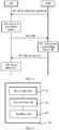
- FIG. 1 is a flowchart of a method for determining a precoding matrix indicator according to an embodiment of the present invention.
- the method in FIG. 1 is executed by user equipment (for example, UE).
- user equipment for example, UE
- 102 Select a precoding matrix based on the first reference signal set, where the precoding matrix is a function of a user equipment-specific matrix or matrix set.
- a first reference signal set is associated with a user equipment-specific matrix or matrix set
- a precoding matrix is a function of the user equipment-specific matrix or matrix set, so that user equipment can select, based on the user equipment-specific matrix or matrix set, the precoding matrix and feed back a PMI
- a set of the precoding matrix forms a user equipment-specific codebook but not a cell specific codebook or system specific codebook (cell specific codebook or system specific codebook).
- the cell specific codebook or system specific codebook is a precoding matrix set designed for all users in a cell or a system, while the user equipment-specific codebook is a subset of the cell specific codebook or system specific codebook. Therefore, in this embodiment of the present invention, CSI feedback precision can be improved without excessively increasing feedback overhead, thereby improving system performance.
- a matrix may include a multi-row multi-column matrix, or may also include a multi-row single-column vector, a single-row multi-column vector, or a scalar (single-row single-column matrix).
- the user equipment-specific matrix or matrix set is notified by the base station to the user equipment.
- the user equipment may further receive a second reference signal set sent by the base station, where the second reference signal set is associated with a matrix or matrix set. Based on the second reference signal set, the user equipment determines and sends a second index to the base station. The second index is used for indicating an antenna port or antenna port subset selected by the user equipment, or a subset of a matrix or matrix set that is associated with the antenna port or antenna port subset selected by the user equipment.
- the first reference signal set may be a subset of the second reference signal set.
- the user equipment when receiving the second reference signal set sent by the base station, may receive reference signals of the second reference signal set that are sent at different times by the base station.
- different times may be associated with a same matrix or different matrices separately, or may be associated with a same subset or different subsets of a matrix set separately.
- the matrix or matrix set associated with the second reference signal set is cell specific or system specific.
- the first reference signal set includes one or more reference signal subsets, and the reference signal subset corresponds to a co-polarized antenna port subset, or corresponds to an antenna port subset that is arranged in a same direction in an antenna port array, or corresponds to a quasi-co-location (Quasi-Co-Location, QCL for short) antenna port subset.
- the reference signal subset corresponds to a co-polarized antenna port subset, or corresponds to an antenna port subset that is arranged in a same direction in an antenna port array, or corresponds to a quasi-co-location (Quasi-Co-Location, QCL for short) antenna port subset.
- the user equipment when receiving the first reference signal set sent by the base station, may receive reference signals of the first reference signal set that are sent at different times by the base station.
- different times may be associated with a same matrix or different matrices separately, or may be associated with a same subset or different subsets of a matrix set separately.
- the precoding matrix w is a product of two matrices W 1 and W 2 .
- W W 1 W 2
- the matrix W 1 is a block diagonal matrix.
- the block diagonal matrix includes at least one block matrix, and each block matrix is a function of the user equipment-specific matrix or matrix set.
- the matrix W 2 is used for selection or weighted combination of column vectors in the matrix W 1 , so as to form the matrix W .
- column vectors of the matrix C or matrix D that corresponds to the block matrix X at a different location on a diagonal in W 1 satisfy the expressions (2) to (5) does not mean that the block matrix X at a different location on a diagonal in W 1 has a same matrix C or matrix D; in contrast, the block matrix X at a different location may have a same or different matrix C or matrix D.
- a matrix in the user equipment-specific matrix or matrix set is a matrix formed by columns being discrete Fourier transformation (DFT, Discrete Fourier Transformation) vectors, or a matrix formed by column vectors of a Hadamard (Hadamard) matrix or a Householder (Householder) matrix.
- DFT discrete Fourier transformation
- Hadamard Hadamard
- Householder Householder
- the first reference signal set includes at least one reference signal subset, and the reference signal subset is associated with a set of the matrix C or the matrix D.
- the reference signal subset has a sending period longer than that of another reference signal.
- the precoding matrix W may be the following matrix: 2 M ⁇ 1 2 1 e j ⁇ ⁇ e j M ⁇ 1 ⁇ e j ⁇ e j ⁇ + ⁇ ⁇ e j ⁇ + M ⁇ 1 ⁇ T or, 4 M ⁇ 1 2 1 e j ⁇ ⁇ e j M ⁇ 1 ⁇ e j ⁇ e j ⁇ + ⁇ ⁇ e j ⁇ + M ⁇ 1 ⁇ T e j ⁇ 1 e j ⁇ ⁇ e j M ⁇ 1 ⁇ e j ⁇ e j ⁇ + M ⁇ 1 ⁇ T or, 2 NM ⁇ 1 2 1 e j ⁇ ⁇ e j M ⁇ 1 ⁇ T e j ⁇ 1 e j ⁇ ⁇ e j M ⁇ 1 ⁇ T ⁇ e j N ⁇ 1 ⁇ 1 e j ⁇ ⁇ ⁇ T or, 4 M ⁇ 1 2 1 e j ⁇ ⁇
- M is a positive integer; for example, a value of M may be 1, 2, 4, 6, 8, 16, 32, 64, and so on.
- N is a positive integer; for example, a value of N may be 1,2,4, 6, 8, 16, 32, 64, and so on.
- the precoding matrix W may be the following matrix: 4 NM ⁇ 1 2 1 e j ⁇ ⁇ e j M ⁇ 1 ⁇ T 1 e j ⁇ ⁇ e j M ⁇ 1 ⁇ T e j ⁇ 1 e j ⁇ ⁇ e j M ⁇ 1 ⁇ T e j ⁇ 1 e j ⁇ ⁇ e j M ⁇ 1 ⁇ T ... ... e j N ⁇ 1 ⁇ 1 e j ⁇ ⁇ e j M ⁇ 1 ⁇ T e j N ⁇ 1 ⁇ 1 e j ⁇ ⁇ e j M ⁇ 1 ⁇ T 1 e j ⁇ ⁇ e j M ⁇ 1 ⁇ T ⁇ 1 e j ⁇ ⁇ e j M ⁇ 1 ⁇ T e j ⁇ 1 ⁇ T e j ⁇ 1 ⁇ T e j ⁇ 1 ⁇ T e j ⁇ 1 e j ⁇ 1 e j ⁇ 1 ⁇
- M is a positive integer; for example, a value of M may be 1, 2, 4, 6, 8, 16, 32, 64, and so on.
- N is a positive integer; for example, a value of N may be 1, 2, 4, 6, 8, 16, 32, 64, and so on.
- the precoding matrix W may match an actually deployed antenna configuration; because granularity of a value of ⁇ is ⁇ /16, more precise space quantization can be implemented, and feedback precision of CSI can be improved; besides, two columns of the precoding matrix W are orthogonal to each other, and interference between layers can be reduced.
- FIG. 2 is a flowchart of a method for determining a precoding matrix indicator according to another embodiment of the present invention.
- the method in FIG. 2 is executed by a base station (for example, eNB).
- a base station for example, eNB
- 201 Send a first reference signal set to user equipment, where the first reference signal set is associated with a user equipment-specific (UE specific) matrix or matrix set.
- UE specific user equipment-specific
- 202 Receive a precoding matrix indicator PMI sent by the user equipment, where the PMI is used for indicating a precoding matrix that is selected based on the first reference signal by the user equipment, and the precoding matrix is a function of the user equipment-specific matrix or matrix set.
- a first reference signal set is associated with a subset of a user equipment-specific matrix or matrix set
- a precoding matrix is a function of the user equipment-specific matrix or matrix set, so that user equipment can select, based on the subset of the matrix or matrix set, the precoding matrix and feed back a PMI
- a set of the precoding matrix forms a user equipment-specific codebook but not a cell specific codebook or system specific codebook.
- the cell specific codebook or system specific codebook is a precoding matrix set designed for all users in a cell or a system
- the user equipment-specific codebook is a subset of the cell specific codebook or system specific codebook. Therefore, in this embodiment of the present invention, CSI feedback precision can be improved without excessively increasing feedback overhead, thereby improving system performance.
- the precoding matrix may also be obtained according to the received PMI.
- the user equipment-specific matrix or matrix set is notified by the base station to the user equipment.
- the base station may further send a second reference signal set to the user equipment, where the second reference signal set is associated with a matrix or matrix set. Then, the base station receives a second index that is determined based on the second reference signal set by the user equipment. The second index is used for indicating an antenna port or antenna port subset selected by the user equipment, or a matrix or matrix set that is associated with the antenna port or antenna port subset selected by the user equipment.
- the first reference signal set is a subset of the second reference signal set.
- the base station when sending the second reference signal set to the user equipment, may send reference signals of the second reference signal set to the user equipment at different times.
- the matrix or matrix set associated with the second reference signal set is cell specific or system specific.
- the base station may further measure an uplink physical channel or an uplink physical signal, to obtain channel estimation of the user equipment according to channel reciprocity. Based on a predefined criterion, the first reference signal and the user equipment-specific matrix or matrix set are selected for a user.
- the uplink physical channel may be a physical uplink control channel (Physical Uplink Control Channel, PUCCH for short) or a physical uplink shared channel (Physical Uplink Shared Channel, PUSCH for short); the physical signal may be a sounding reference signal (Sounding Reference Signal, SRS for short) or another uplink demodulation reference signal (DeModulation Reference signal, DMRS for short).
- the first reference signal set may include one or more reference signal subsets.
- the reference signal subset corresponds to a co-polarized antenna port subset, or corresponds to an antenna port subset that is arranged in a same direction in an antenna port array, or corresponds to a quasi-co-location antenna port subset.
- the base station may send subsets of the first reference signal set to the user equipment at different times.
- different times may be associated with a same matrix or different matrices separately, or may be associated with a same subset or different subsets of a matrix set separately.
- the matrix W 2 is used for selection or weighted combination of column vectors in the matrix W 1 , so as to form the matrix W .
- columns of at least one matrix in the two matrices C and D are rotations of column vectors in a matrix in the user equipment-specific matrix or matrix set, that is, a k th column vector c k of the matrix c is shown in the expression (2) or (3); or, an 1 th column vector d l of the matrix D is shown in the expression (4) or (5), where N V , N H , N C , and N D are positive integers, a m is an m th column vector of a matrix A, and the matrix A is a matrix in the user equipment-specific matrix or matrix set.
- column vectors of the matrix C or matrix D that corresponds to the block matrix X at a different location on a diagonal in W 1 satisfy the expressions (2) to (5) does not mean that the block matrix X at a different location on a diagonal in W 1 has a same matrix C or matrix D; in contrast, the block matrix X at a different location may have a same or different matrix C or matrix D.
- a matrix in the user equipment-specific matrix or matrix set is a matrix formed by columns being DFT vectors, or a matrix formed by column vectors of a Hadamard matrix or a Householder matrix.
- the DFT vector a l is shown in the expression (6), where N C ⁇ N or N D ⁇ N.
- the first reference signal set includes at least one reference signal subset, and the reference signal subset is associated with a set of the matrix C or the matrix D.
- the reference signal subset has a sending period longer than that of another reference signal.
- the precoding matrix W may be the following matrix: 2 M ⁇ 1 2 1 e j ⁇ ⁇ e j M ⁇ 1 ⁇ e j ⁇ e j ⁇ + ⁇ ⁇ e j ⁇ + M ⁇ 1 ⁇ T or, 4 M ⁇ 1 2 1 e j ⁇ ⁇ e j M ⁇ 1 ⁇ e j ⁇ e j ⁇ + ⁇ ⁇ e j ⁇ + M ⁇ 1 ⁇ T e j ⁇ 1 e j ⁇ ⁇ e j M ⁇ 1 ⁇ e j ⁇ e j ⁇ + M ⁇ 1 ⁇ T or, 2 NM ⁇ 1 2 1 e j ⁇ ⁇ e j M ⁇ 1 ⁇ T e j ⁇ 1 e j ⁇ ⁇ e j M ⁇ 1 ⁇ T ... e j N ⁇ 1 ⁇ 1 e j ⁇ ⁇ ⁇ T or, 4 M ⁇ 1 2 1 e j ⁇ ⁇
- M is a positive integer; for example, a value of M may be 1, 2, 4, 6, 8, 16, 32, 64, and so on.
- N is a positive integer; for example, a value of N may be 1, 2, 4, 6, 8, 16, 32, 64, and so on.
- the precoding matrix W may be the following matrix: 4 NM ⁇ 1 2 1 e j ⁇ ⁇ e j M ⁇ 1 ⁇ T 1 e j ⁇ ⁇ e j M ⁇ 1 ⁇ T e j ⁇ 1 e j ⁇ ⁇ e j M ⁇ 1 ⁇ T e j ⁇ 1 e j ⁇ ⁇ e j M ⁇ 1 ⁇ T ... ... e j N ⁇ 1 ⁇ 1 e j ⁇ ⁇ e j M ⁇ 1 ⁇ T e j N ⁇ 1 ⁇ 1 e j ⁇ ⁇ e j M ⁇ 1 ⁇ T 1 e j ⁇ ⁇ e j M ⁇ 1 ⁇ T ⁇ 1 e j ⁇ ⁇ e j M ⁇ 1 ⁇ T e j ⁇ 1 ⁇ T e j ⁇ 1 ⁇ T e j ⁇ 1 ⁇ T e j ⁇ 1 e j ⁇ 1 e j ⁇ 1 ⁇
- M is a positive integer; for example, a value of M may be 1, 2, 4, 6, 8, 16, 32, 64, and so on.
- N is a positive integer; for example, a value of N may be 1, 2, 4, 6, 8, 16, 32, 64, and so on.
- the precoding matrix W may match an actually deployed antenna configuration; because granularity of a value of ⁇ is ⁇ /16, more precise space quantization can be implemented, and feedback precision of CSI can be improved; besides, two columns of the precoding matrix W are orthogonal to each other, and interference between layers can be reduced.
- an eNB is used as an example of a base station
- UE is used as an example of user equipment, but the embodiments of the present invention are not limited thereto, and may also be applied to other communications systems.
- FIG. 3 is a schematic flowchart of a multi-antenna transmission method according to an embodiment of the present invention.
- UE receives a first reference signal set, where the first reference signal set is associated with a user equipment-specific (UE-specific) matrix or matrix set.
- UE-specific user equipment-specific
- the first reference signal set received by the UE is notified by an eNB by using higher layer signaling, or is dynamically notified by an eNB by using a downlink control channel.
- the reference signal may be a cell specific reference signal (CRS, Cell specific RS), or a demodulation reference signal (DMRS, DeModulation RS), or a channel state information reference signal (CSI-RS, channel state information RS).
- CRS cell specific reference signal
- DMRS demodulation reference signal
- CSI-RS channel state information reference signal
- the reference signal may correspond to a physical antenna, or may also correspond to a virtual antenna, where the virtual antenna is a weighted combination of multiple physical antennas.
- the first reference signal set may include one or more reference signal subsets.
- the first reference signal set received by the UE is P, which includes in total eight reference signals, namely, p1, p2, p3, ..., p7, and p8.
- the first reference signal set may include one reference signal subset.
- the reference signal subset is the same as the first reference signal set, that is, the eight reference signals p1, p2, ..., and s8 in P.
- the first reference signal set may include multiple reference signal subsets.
- the reference signal subset included in the first reference signal set may correspond to a co-polarized antenna port subset.
- the reference signal subset included in the first reference signal set may correspond to a port subset that is arranged in a same direction in an antenna port array.
- the subset P2 ⁇ p5, p 6, p7, p8 ⁇ of the first reference signal set corresponds to an antenna port subset of a row in a horizontal direction in the antenna port array.
- the reference signal subset included in the first reference signal set may correspond to a quasi-co-location antenna port subset.
- the subset PI ⁇ p1, p2, p3, p4 ⁇ of the first reference signal set corresponds to a quasi-co-location antenna port subset.
- the subset PI ⁇ p5, p 6, p7, p8 ⁇ of the first reference signal set corresponds to an antenna port subset that is located at another quasi-co-location.
- the quasi-co-location (QCL, Quasi-Co-Location) antenna port refers to that a distance between antennas corresponding to the antenna port is within a range that uses a wavelength as a dimension.
- each of the foregoing antenna ports corresponds to a physical antenna or virtual antenna, where the virtual antenna is a weighted combination of multiple physical antennas or antenna array elements.
- reference signals in the multiple reference signal subsets included in the first reference signal set may occupy different symbol/frequency/sequence resources and be transmitted at a same subframe, or may occupy a same symbol/frequency/sequence resource and be transmitted at different subframes.
- the foregoing division of the reference signal subset may further reduce complexity of implementation.
- the first reference signal set is associated with a subset of a user equipment-specific (UE-specific) matrix or matrix set; or each reference signal in the first reference signal set may be associated with a subset of a user equipment-specific (UE-specific) matrix or matrix set.
- the reference signal set notified by the eNB is S, which includes in total eight reference signals, namely s1, s2, s3, ..., s7, and s8.
- the foregoing reference signals are associated with matrices w1, w2, ..., and w8 separately, or are associated with ⁇ w1,w2 ⁇ , ⁇ w2,w3 ⁇ , ..., ⁇ w7,w8 ⁇ , and ⁇ w8,w1 ⁇ separately.
- the first reference signal set is associated with a subset of a matrix or matrix set, or a reference signal subset of the first reference signal set may be associated with a subset of a user equipment-specific matrix or matrix set.
- the reference signal set notified by the eNB is S, which includes in total eight reference signals, namely s1, s2, s3, ..., s7, and s8.
- a reference signal subset ⁇ s1, s2, s3, s4 ⁇ is associated with a matrix p1 or a matrix subset ⁇ p1, ..., pm ⁇
- a reference signal subset ⁇ s5, s6, s7, s8 ⁇ is associated with a matrix w1 or a matrix subset ⁇ w1, ..., wn ⁇ , where m and n are positive integers.
- reference signal subsets ⁇ s1, s2 ⁇ , ⁇ s3, s4 ⁇ , ..., and ⁇ s7, s8 ⁇ are associated with matrices w1, w2, w3, and w4 respectively.
- reference signal subsets ⁇ s1, s2 ⁇ , ⁇ s3, s4 ⁇ , ..., and ⁇ s7, s8 ⁇ are associated with matrices ⁇ w1, w2 ⁇ , ⁇ w3, w4 ⁇ , ..., and ⁇ w7, w8 ⁇ respectively.
- the matrix herein includes a vector.
- an association or a correspondence between the first reference signal set and a user equipment-specific matrix or matrix set may be notified by using signaling. For example, it is notified by using higher layer signaling, for example, radio resource control (RRC, Radio Resource Control) signaling, that the reference signal subset ⁇ s1, s2, s3, s4 ⁇ is associated with a matrix p1 or a matrix subset ⁇ p1, ..., pm ⁇ , and the reference signal subset ⁇ s5, s6, s7, s8 ⁇ is associated with a matrix w1 or a matrix subset ⁇ w1, ..., wn ⁇ .
- RRC Radio Resource Control
- the association or correspondence between the first reference signal set and a user equipment-specific matrix or matrix set is dynamically notified by using downlink control information (DCI, Downlink Control information).
- DCI Downlink Control information
- multiple candidate association relationships are notified by using higher layer signaling, for example RRC signaling, and one of the candidate association relationships is further dynamically notified by using DCI.
- each matrix subset in the signaling may be represented by a bitmap (bitmap).
- the RRC signaling may be UE-specific signaling, for example, dedicated physical signaling.
- the first reference signal set and indication information of the UE-specific matrix or matrix set may be sent in same RRC dedicated signaling.
- an association relationship or mapping between the first reference signal set and a user equipment-specific matrix or matrix set may also be predefined.
- the reference signal subset ⁇ s1, s2, s3, s4 ⁇ is associated with a matrix p1 or a matrix subset ⁇ p1, ..., pm ⁇
- the reference signal subset ⁇ s5, s6, s7, s8 ⁇ is associated with a matrix w1 or a matrix subset ⁇ w1, ..., wn ⁇ .
- the first reference signal set is associated with a subset of a matrix or matrix set, or the first reference signal set may be associated with a matrix or matrix set, where a subset of the matrix or matrix set is notified by using signaling or is predefined.
- a matrix or matrix subset is notified by using higher layer signaling, for example, RRC signaling, or is dynamically notified by using DCI; or, a matrix set is notified by using higher layer signaling, for example, RRC signaling, and one matrix subset in the matrix set is further dynamically notified by using DCI.
- the matrix in the user equipment-specific (UE specific) matrix or the matrix set may also use a matrix in another form, for example, a Householder matrix, or a precoding matrix in an LTE R8 4-antenna or LTE R10 8-antenna codebook.
- vectors c k and d k in the expressions (24) to (27) may have granularity finer than that of a l and b l respectively, that is, N C ⁇ N or N D ⁇ N ′
- a set formed by the foregoing vector or matrix A or B or Y or W is C A or C B or C Y or C W , and may be further divided into multiple subsets (the subset may include only one element), and each subset may be associated with or have a mapping relationship with a user equipment identifier.
- a subset C A 1 in C A is associated with or is mapped to a user equipment identifier ID 1
- another subset C A 2 in C A is associated with or is mapped to a user equipment identifier ID 2
- the subsets C A 1 and C A 2 may intersect, or may not intersect.
- An association or a mapping relationship between the foregoing vector or matrix or subset of the matrix with the user equipment identifier may be predefined, or may also be notified by the eNB to the UE, for example, notified by using higher layer signaling, for example, RRC signaling or a downlink control channel. Each subset may include only one element.
- the reference signal set may be associated with a user equipment identifier.
- the reference signal set notified by the eNB is S, which includes in total eight reference signals, namely s1, s2, s3, ..., s7, and s8.
- the foregoing reference signal is associated with a user equipment identifier ID 0 ; or the reference signal set received by the UE may be divided into two or more subsets, and the subsets are associated with specific user equipment identifiers separately.
- the reference signal set received by the UE may be divided into two subsets, one including reference signals s1, s2, s3, and s4 and the other s5, s6, s7, and s8, and then s1, s2, s3, and s4 are associated with identifiers user equipment ID 1 and ID 2 .
- An association or a mapping relationship between the reference signal set and a user equipment identifier may be predefined, or may also be notified by the eNB.
- the user equipment identifier is not necessarily a UE ID in a specific communications protocol, for example, LTE, but may also be a specific parameter that is used to distinguish a user equipment attribute, for example, an index or an offset in a user group or a UE group, or simply an index or an offset used in a same user group or UE group.
- the offset or index facilitates implementation of distinguishing of attributes related to different beams among user equipments or user groups.
- reference signals in the reference signal set may be sent at different times, for example, different subframes, and the different times may be associated with or mapped to different vectors/matrices or different subsets of matrix sets.
- the different vectors/matrices or different subsets of matrix sets that the reference signals are associated with or mapped to at different times may be predefined, or may also be notified by the eNB, for example, notified by using RRC signaling.
- the UE selects a precoding matrix based on the first reference signal set, where the precoding matrix is a function of the user equipment-specific matrix or matrix set.
- At least one of the matrix A or the matrix B is a matrix in the user equipment-specific matrix or matrix set.
- the block matrices X 1 and X 2 each have 4 columns
- the block matrices X 1 and X 2 each have 8 columns
- the matrix W 2 may be represented as: W 2 ⁇ 1 2 Y Y , 1 2 Y jY , 1 2 Y ⁇ Y , 1 2 Y ⁇ jY Y ⁇ e 1 e 2 e 3 e 4 e 5 e 6 e 7 e 8 or, W 2 ⁇ 1 2 Y 1 Y 2 Y 1 ⁇ Y 2 , 1 2 Y 1 Y 2 j Y 1 ⁇ j Y 2 Y 1 Y 2 ⁇ e 1 e 1 e 2 e 2 e 3 e 3 e 4 e 4 e 1 e 2 e 2 e 3 e 1 e 4 e 2 e 4
- the block matrix X is a function of the matrix A or B .
- vectors c k and d k in the expressions (47) to (50) may have granularity finer than that of a l and b l , that is, N D ⁇ N or N D ⁇ N
- the UE sends a precoding matrix indicator PMI to the base station, where the PMI corresponds to the selected precoding matrix.
- the precoding matrix indicator PMI may include one or more indexes.
- the precoding matrix indicator PMI may include one index.
- the index indicates directly the precoding matrix W .
- the precoding matrix indicator PMI may also be two indexes, for example, i 1 and i 2 .
- W 1 and W 2 in the expression (29) are indicated by using i 1 and i 2 respectively, so that i 1 and i 2 indicate the precoding matrix W .
- the index i 1 may be reported based on a subset of W 1 .
- a universal set of W 1 is Q, and subsets of the set Q are Q 0 , ..., and Q .3 separately.
- the index i 1 is used to indicate a matrix W 1 in a subset Q k , where Q k may be one subset in Q 0 , Q 1 ..., and Q 3 .
- Qk may be predefined, or may be determined and reported by the UE, or may also be notified by the eNB to the UE.
- the subsets Q0, ..., and Q3 may not intersect with each other, that is, an intersection set of the subsets is an empty set; or the subsets Q0, ..., and Q3 may intersect with each other, that is, an intersection set of the subsets is not an empty set.
- i 3 , i 4 , and i 5 there may also be three indexes reported by the UE and used to indicate the precoding matrix, for example, i 3 , i 4 , and i 5 .
- X 1 and X 2 in the expression (30) are implicitly indicated by using i 3 and i 4 respectively, and W 2 is implicitly indicated by using i 5 . Therefore, i 3 , i 4 , and i 5 indicate the precoding matrix W .
- the index i 3 may be reported based on a subset of X 1 .
- a universal set of X 1 is R, and subsets of the set R are R 0 , ..., and R 7 separately.
- the index i 3 is used to indicate a matrix X 1 in a subset R k .
- R k may be one subset in R 0 , R 1 ..., and R 7 .
- R k may be predefined, or may be determined and reported by the UE, or may also be notified by the eNB to the UE.
- the subsets R 0 , ..., and R 7 may not intersect with each other, that is, an intersection set of the subsets is an empty set; or the subsets R 0 , ..., and R 7 may intersect with each other, that is, an intersection set of the subsets is not an empty set; similarly, i 4 and i 5 may be reported based on subsets of X 2 and W 2 respectively.
- the subsets of X 2 and W 2 may be predefined, or may be determined and reported by the UE, or may also be notified by the eNB to the UE.
- indexes reported by the UE and used to indicate the precoding matrix may also be other three indexes, for example, i6, i7 and i8.
- the index i 6 may be reported based on a subset of C i .
- a universal set of C i is O, and subsets of the set O are O 0 , ..., and O 7 separately.
- the index i 6 is used to indicate a matrix C i in a subset O k .
- O k may be one subset in O 0 , O 1 ..., and O 7 .
- O k may be predefined, or may also be determined and reported by the UE, or may also be notified by the eNB to the UE.
- the subsets O 0 , ..., and O 7 may not intersect with each other, that is, an intersection set of the subsets is an empty set; or the subsets O 0 , ..., O 7 may intersect with each other, that is, an intersection set of the subsets is not an empty set; similarly, i 7 and i 8 may be reported based on subsets of D i and W 2 respectively.
- the subsets of D i and W 2 may be predefined, or may be determined and reported by the UE, or may also be notified by the eNB to the UE.
- indexes reported by the UE and used to indicate the precoding matrix may also be four indexes, for example, i 9 , i 10 , i 11 , and i 12 .
- i 9 , i 10 , i 11 , and i 12 may be reported based on subsets of C 1 , C 2 , D i , and W 2 respectively.
- the subsets of C 1 , C 2 , D i , and W 2 may be predefined, or may be determined and reported by the UE, or may also be notified by the eNB to the UE.
- the index value may be calculated based on one reference signal subset.
- the foregoing index value n is calculated based on the reference signal subset P in step 301, or the index values i 1 and i 2 , or i 3 , i 4 , and i 5 , or i 6 , i 7 , and i 8 , or i 9 , i 10 , i 11 , and i 12 are calculated based on the reference signal subset P in step 1.
- the index value may be calculated in combination based on multiple reference signal subsets.
- the index value n is calculated based on the reference signal subsets P1 and P2 in step 301, or the index values i 1 and i 2 , or i 3 , i 4 , and i 5 , or i 6 , i 7 , and i 8 , or i 9 , i 10 , i 11 , and i 12 are calculated based on the reference signal subsets P1 and P2 in step 1.
- the index values are calculated separately based on multiple reference signal subsets.
- the index value i 3 is calculated based on the reference signal subset PI in step 301
- the index values i 4 and i 5 are calculated based on the reference signal subset P2 in step 301.
- the index value i 6 is calculated based on the reference signal subset PI in step 301
- the index values i 7 and i 8 are calculated based on the reference signal subset P2 in step 301.
- the index values i 9 and i 10 are calculated based on the reference signal subset PI in step 301
- the index values i 11 and i 12 are calculated based on the reference signal subset P2 in step 301.
- the UE may determine the foregoing one or more indexes according to a measured channel state based on a preset criterion, and the preset criterion may be a maximum throughput criterion or a maximum capacity criterion. After the one or more indexes are obtained, the UE may feed back the indexes to the eNB by using a PUCCH or a PUSCH.
- the precoding matrix indicator PMI may include one or more indexes, and the UE may report the indexes to the eNB through different subframes by using a physical uplink control channel (PUCCH, Physical Uplink Control Channel).
- PUCCH Physical Uplink Control Channel
- the foregoing multiple different indexes may be reported to the eNB through different subframes for different subbands on a frequency domain.
- matrices corresponding to the indexes may be single matrices, so that corresponding indexes do not need to be fed back.
- the single matrix may be a predefined matrix, or may also be notified by a base station by using signaling, or may also be obtained implicitly according to other parameters.
- W 2 is fixedly selected as the matrix shown in the expression (51), so that an index corresponding to W 2 does not need to be fed back. In this case, W 2 is obtained implicitly according to a rank r of the precoding matrix.
- the base station obtains the precoding matrix W based on the received precoding matrix indicator PMI.
- the base station uses the precoding matrix W to transmit a signal vector S . Specifically, after precoding, a transmitted signal vector is Ws .
- a first reference signal set is associated with or corresponds to a user equipment-specific matrix or matrix set
- a precoding matrix is a function of the user equipment-specific matrix or matrix set. Therefore, user equipment can select, based on the user equipment-specific matrix or matrix set, the precoding matrix and feed back a PMI, and a set of the precoding matrix forms a user equipment-specific codebook but not a cell specific codebook or system specific codebook.
- the cell specific codebook or system specific codebook is a precoding matrix set designed for all users in a cell or a system, while the user equipment-specific codebook is a subset of the cell specific codebook or system specific codebook. Therefore, in this embodiment of the present invention, CSI feedback precision can be improved without excessively increasing feedback overhead, thereby improving system performance.
- one or more indexes are fed back based on a subset to indicate a precoding matrix, and correlation between time/frequency domain/space of a channel is fully utilized, so that feedback overhead is greatly reduced.
- step 301 of receiving a first reference signal set sent by a base station the following optional steps may further be included:
- the first reference signal set is a subset of the second reference signal set, or the second reference signal set is a superset of the first reference signal set.
- the first reference signal set is a subset of the second reference signal set (or equivalently, the second reference signal set is a superset of the first reference signal set) includes that: the second reference signal set is the same as the first reference signal set; or the second reference signal set is a proper subset of the first reference signal set, and in this case, a quantity of reference signals included in the second reference signal set is less than a quantity of reference signals included in the first reference signal set.
- the base station uses a reference signal or a reference signal subset corresponding to the antenna port or antenna port subset, initially selected by the UE and indicated by the second index that is reported by the UE, in the second reference signal set, as the first reference signal set; or the base station uses a subset of a matrix or matrix set that is associated with the antenna port or antenna port subset initially selected by the UE and indicated by the second index that is reported by the UE, as a matrix or matrix set that is associated with the first reference signal set.
- the base station may refer to the second index as assistance, but the base station also may not refer to the second index.
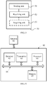
- FIG. 4 is a block diagram of user equipment according to an embodiment of the present invention.
- the user equipment 40 in FIG. 4 includes a receiving unit 41, a determining unit 42, and a sending unit 43.
- the receiving unit 41 receives a first reference signal set sent by a base station, where the first reference signal set is associated with a user equipment-specific (UE-specific) matrix or matrix set.
- the determining unit 42 selects a precoding matrix based on the first reference signal set, where the precoding matrix is a function of the user equipment-specific matrix or matrix set.
- the sending unit 43 sends a precoding matrix indicator PMI to the base station, where the PMI corresponds to the selected precoding matrix.
- a first reference signal set is associated with or corresponds to a user equipment-specific matrix or matrix set
- a precoding matrix is a function of the user equipment-specific matrix or matrix set, so that the PMI can select, based on the user equipment-specific matrix or matrix set, the precoding matrix and feed back a PMI
- a set of the precoding matrix forms a user equipment-specific codebook but not a cell specific codebook or system specific codebook.
- the cell specific codebook or system specific codebook is a precoding matrix set designed for all users in a cell or a system
- the user equipment-specific codebook is a subset of the cell specific codebook or system specific codebook. Therefore, in this embodiment of the present invention, CSI feedback precision can be improved without excessively increasing feedback overhead, thereby improving system performance.
- the receiving unit 41 is further configured to receive the user equipment-specific matrix or matrix set notified by the base station.
- the receiving unit is further configured to: before the first reference signal set is received, receive a second reference signal set sent by the base station, where the second reference signal set is associated with a matrix or matrix set; the determining unit is further configured to determine a second index based on the second reference signal set, where the second index is used for indicating an antenna port or antenna port subset selected by the user equipment, or a matrix or matrix set that is associated with the antenna port or antenna port subset selected by the user equipment; and the sending unit is further configured to send the second index to the base station.
- the first reference signal set is a subset of the second reference signal set.
- the matrix or matrix set associated with the second reference signal set is cell specific or system specific.
- the receiving unit is specifically configured to receive reference signals of the second reference signal set that are sent at different times by the base station.
- different times may be associated with a same matrix or different matrices separately, or may be associated with a same subset or different subsets of a matrix set separately.
- the first reference signal set includes one or more reference signal subsets, and the reference signal subset corresponds to a co-polarized antenna port subset, or corresponds to an antenna port subset that is arranged in a same direction in an antenna port array, or corresponds to an antenna port subset that is located at a quasi-co-location.
- the receiving unit is specifically configured to receive reference signals of the first reference signal set that are sent at different times by the base station.
- different times may be associated with a same matrix or different matrices separately, or may be associated with a same subset or different subsets of a matrix set separately.
- the matrix W 2 is used for selection or weighted combination of column vectors in the matrix W 1 , so as to form the matrix W .
- columns of at least one matrix in the two matrices C and D are rotations of column vectors in a matrix in the user equipment-specific matrix or matrix set, that is, a k th column vector c k of the matrix C is shown in the expression (2) or (3); or, an 1 th column vector d l of the matrix D is shown in the expression (4) or (5), where N V , N H , N C , and N D are positive integers, a m is an m th column vector of a matrix A, and the matrix A is a matrix in the user equipment-specific matrix or matrix set.
- column vectors of the matrix C or matrix D that corresponds to the block matrix X at a different location on a diagonal in W 1 satisfy the expressions (2) to (5) does not mean that the block matrix X at a different location on a diagonal in W 1 has a same matrix C or matrix D; in contrast, the block matrix X at a different location may have a same or different matrix C or matrix D.
- a matrix in the user equipment-specific matrix or matrix set is a matrix formed by columns being DFT vectors, or a matrix formed by column vectors of a Hadamard matrix or a Householder matrix.
- the DFT vector a l is shown in the expression (6), where N C ⁇ N or N D ⁇ N.
- the first reference signal set includes at least one reference signal subset, and the reference signal subset is associated with a set of the matrix C or the matrix D.
- the reference signal subset has a sending period longer than that of another reference signal.
- FIG. 5 is a block diagram of a base station according to an embodiment of the present invention.
- the base station 50 in FIG. 5 includes a sending unit 51 and a receiving unit 52.
- the sending unit 51 is configured to send a first reference signal set to user equipment, where the first reference signal set is associated with a user equipment-specific (UE-specific) matrix or matrix set; and the receiving unit 52 is configured to receive a precoding matrix indicator PMI sent by the user equipment, where the PMI is used for indicating a precoding matrix that is selected based on the first reference signal by the user equipment, and the precoding matrix is a function of the user equipment-specific matrix or matrix set.
- UE-specific user equipment-specific
- a first reference signal set is associated with or corresponds to a user equipment-specific matrix or matrix set
- a precoding matrix is a function of the user equipment-specific matrix or matrix set, so that user equipment can select, based on the matrix or matrix set, the precoding matrix and feed back a PMI
- a set of the precoding matrix forms a user equipment-specific codebook but not a cell specific codebook or system specific codebook.
- the cell specific codebook or system specific codebook is a precoding matrix set designed for all users in a cell or a system, while the user equipment-specific codebook is a subset of the cell specific codebook or system specific codebook. Therefore, in this embodiment of the present invention, CSI feedback precision can be improved without excessively increasing feedback overhead, thereby improving system performance.
- the base station 50 may further include an acquiring unit 53, configured to obtain the precoding matrix according to the received PMI.
- the sending unit 51 is further configured to notify the user equipment of the user equipment-specific matrix or matrix set.
- the sending unit 51 is further configured to: before the first reference signal set is sent to the user equipment, send a second reference signal set to the user equipment, where the second reference signal set is associated with a matrix or matrix set; and the receiving unit is further configured to receive a second index that is determined based on the second reference signal set by the user equipment, where the second index is used for indicating an antenna port or antenna port subset selected by the user equipment, or a matrix or matrix set that is associated with the antenna port or antenna port subset selected by the user equipment.
- the first reference signal set is a subset of the second reference signal set.
- the matrix or matrix set associated with the second reference signal set is cell specific or system specific.
- the acquiring unit 53 is further configured to measure an uplink physical channel or an uplink physical signal, and obtain channel estimation of the user equipment according to channel reciporocity. Based on a predefined criterion, the first reference signal and the user equipment-specific matrix or matrix set are selected for a user.
- the uplink physical channel may be a physical uplink control channel (Physical Uplink Control Channel, PUCCH for short) or a physical uplink shared channel (Physical Uplink Shared Channel, PUSCH for short); the physical signal may be a sounding reference signal (Sounding Reference Signal, SRS for short) or another uplink demodulation reference signal (DeModulation Reference signal, DMRS for short).
- the sending unit is specifically configured to send reference signals of the second reference signal set to the user equipment at different times.
- different times may be associated with a same matrix or different matrices separately, or may be associated with a same subset or different subsets of a matrix set separately.
- the first reference signal set includes one or more reference signal subsets, and the reference signal subset corresponds to a co-polarized antenna port subset, or corresponds to an antenna port subset that is arranged in a same direction in an antenna port array, or corresponds to a quasi-co-location antenna port subset.
- the sending unit is specifically configured to send reference signals of the first reference signal set to the user equipment at different times.
- different times may be associated with a same matrix or different matrices separately, or may be associated with a same subset or different subsets of a matrix set separately.
- the matrix W 2 is used for selection or weighted combination of column vectors in the matrix W 1 , so as to form the matrix W .
- columns of at least one matrix in the two matrices C and D are rotations of column vectors in a matrix in the user equipment-specific matrix or matrix set, that is, a k th column vector c k of the matrix c is shown in the expression (2) or (3); or, an 1 th column vector d l of the matrix D is shown in the expression (4) or (5), where N V , N H , N C , and N D are positive integers, a m is an m th column vector of a matrix A, and the matrix A is a matrix in the user equipment-specific matrix or matrix set.
- column vectors of the matrix c or matrix D that corresponds to the block matrix X at a different location on a diagonal in W 1 satisfy the expressions (2) to (5) does not mean that the block matrix X at a different location on a diagonal in W 1 has a same matrix c or matrix D; in contrast, the block matrix X at a different location may have a same or different matrix C or matrix D .
- a matrix in the user equipment-specific matrix or matrix set is a matrix formed by columns being DFT vectors, or a matrix formed by column vectors of a Hadamard matrix or a Householder matrix.
- the DFT vector a l is shown in the expression (6), where N C ⁇ N or N D ⁇ N.
- the first reference signal set includes at least one reference signal subset, and the reference signal subset is associated with a set of the matrix C or the matrix D.
- the reference signal subset has a sending period longer than that of another reference signal.
- FIG. 6 is a block diagram of user equipment according to another embodiment of the present invention.
- the user equipment 60 in FIG. 6 includes a receiver 62, a transmitter 63, a processor 64, and a memory 65.
- the receiver 62 is configured to receive a first reference signal set sent by a base station, where the first reference signal set is associated with a user equipment-specific (UE specific) matrix or matrix set.
- UE specific user equipment-specific
- the memory 65 stores an instruction that enables the processor 64 to perform the following operation: selecting a precoding matrix based on the first reference signal set, where the precoding matrix is a function of the user equipment-specific matrix or matrix set.
- the transmitter 63 is configured to send a precoding matrix indicator PMI to the base station, where the PMI corresponds to the selected precoding matrix.
- a first reference signal set is associated with or corresponds to a user equipment-specific matrix or matrix set
- a precoding matrix is a function of the user equipment-specific matrix or matrix set, so that the user equipment can select, based on the user equipment-specific matrix or matrix set, the precoding matrix and feed back a PMI
- a set of the precoding matrix forms a user equipment-specific codebook but not a cell specific codebook or system specific codebook.
- the cell specific codebook or system specific codebook is a precoding matrix set designed for all users in a cell or a system
- the user equipment-specific codebook is a subset of the cell specific codebook or system specific codebook. Therefore, in this embodiment of the present invention, CSI feedback precision can be improved without excessively increasing feedback overhead, thereby improving system performance.
- the receiver 62, the transmitter 63, the processor 64, and the memory 65 may be integrated into a processing chip. Alternatively, as shown in FIG. 6 , the receiver 62, the transmitter 63, the processor 64, and the memory 65 are connected by using a bus 66.
- the user equipment 60 may further include an antenna 61.
- the processor 64 may further control an operation of the user equipment 60, and the processor 64 may further be referred to as a CPU (Central Processing Unit, central processing unit).
- the memory 65 may include a read only memory and a random access memory, and provides an instruction and data to the processor 64. A part of the memory 65 may further include a non-volatile random access memory. Components of the user equipment 60 are coupled together by using a bus system 66.
- the bus system 66 may include, in addition to a data bus, a power bus, a control bus, a status signal bus, and the like. However, for the purpose of clear description, all buses are marked as the bus system 66 in the figure.
- the receiver 62 is further configured to receive the user equipment-specific matrix or matrix set notified by the base station.
- the receiver 62 is further configured to: before the first reference signal set is received, receive a second reference signal set sent by the base station, where the second reference signal set is associated with a matrix or matrix set; the memory 65 further stores an instruction that enables the processor 64 to perform the following operation: determining a second index based on the second reference signal set, where the second index is used for indicating an antenna port or antenna port subset selected by the user equipment, or a matrix or matrix set that is associated with the antenna port or antenna port subset selected by the user equipment 60; and the transmitter 63 is further configured to send the second index to the base station.
- the first reference signal set is a subset of the second reference signal set.
- the receiver 62 is specifically configured to receive reference signals of the second reference signal set that are sent at different times by the base station.
- different times may be associated with a same matrix or different matrices separately, or may be associated with a same subset or different subsets of a matrix set separately.
- the first reference signal set includes one or more reference signal subsets, and the reference signal subset corresponds to a co-polarized antenna port subset, or corresponds to an antenna port subset that is arranged in a same direction in an antenna port array, or corresponds to an antenna port subset that is located at a quasi-co-location.
- the receiver 62 is specifically configured to receive reference signals of the first reference signal set that are sent at different times by the base station.
- different times may be associated with a same matrix or different matrices separately, or may be associated with a same subset or different subsets of a matrix set separately.
- the matrix W 2 is used for selection or weighted combination of column vectors in the matrix W 1 , so as to form the matrix W .
- columns of at least one matrix in the two matrices C and D are rotations of column vectors in a matrix in the user equipment-specific matrix or matrix set, that is, a k th column vector c k of the matrix c is shown in the expression (2) or (3); or, an 1 th column vector d l of the matrix D is shown in the expression (4) or (5), where N V , N H , Nc, and N D are positive integers, a m is an m th column vector of a matrix A, and the matrix A is a matrix in the user equipment-specific matrix or matrix set.
- column vectors of the matrix C or matrix D that corresponds to the block matrix X at a different location on a diagonal in W 1 satisfy the expressions (2) to (5) does not mean that the block matrix X at a different location on a diagonal in W 1 has a same matrix C or matrix D; in contrast, the block matrix X at a different location may have a same or different matrix C or matrix D.
- a matrix in a subset of the user equipment-specific matrix or matrix set is a matrix formed by columns being DFT vectors, or a matrix formed by column vectors of a Hadamard matrix or a Householder matrix.
- the DFT vector a l is shown in the expression (6), where N C ⁇ N or N D ⁇ N.
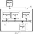
- FIG. 7 is a block diagram of a base station according to another embodiment of the present invention.
- the base station 70 in FIG. 7 includes a transmitter 72, a receiver 73, a processor 74, and a memory 75.
- the transmitter 72 is configured to send a first reference signal set to user equipment, where the first reference signal set is associated with a user equipment-specific (UE specific) matrix or matrix set.
- UE specific user equipment-specific
- the receiver 73 is configured to receive a precoding matrix indicator PMI sent by the user equipment, where the PMI is used for indicating a precoding matrix that is selected based on the first reference signal by the user equipment, and the precoding matrix is a function of the user equipment-specific matrix or matrix set.
- the memory 75 may store an instruction that enables the processor 74 to perform the following operation: obtaining the precoding matrix according to the received PMI.
- a first reference signal set is associated with or corresponds to a user equipment-specific matrix or matrix set
- a precoding matrix is a function of the user equipment-specific matrix or matrix set, so that user equipment can select, based on the user equipment-specific matrix or matrix set, the precoding matrix and feed back a PMI
- a set of the precoding matrix forms a user equipment-specific codebook but not a cell specific codebook or system specific codebook.
- the cell specific codebook or system specific codebook is a precoding matrix set designed for all users in a cell or a system
- the user equipment-specific codebook is a subset of the cell specific codebook or system specific codebook. Therefore, in this embodiment of the present invention, CSI feedback precision can be improved without excessively increasing feedback overhead, thereby improving system performance.
- the transmitter 72, the receiver 73, the processor 74, and the memory 75 may be integrated into a processing chip. Alternatively, as shown in FIG. 6 , the transmitter 72, the receiver 73, the processor 74, and the memory 75 are connected by using a bus 76.
- the base station 70 may further include an antenna 71.
- the processor 74 may further control an operation of the base station 70, and the processor 74 may further be referred to as a CPU (Central Processing Unit, central processing unit).
- the memory 75 may include a read only memory and a random access memory, and provides an instruction and data to the processor 74. A part of the memory 75 may further include a non-volatile random access memory.
- Components of the user equipment 70 are coupled together by using a bus system 76.
- the bus system 76 may include, in addition to a data bus, a power bus, a control bus, a status signal bus, and the like. However, for the purpose of clear description, all buses are marked as the bus system 76 in the figure.
- the transmitter 72 is further configured to notify the user equipment of the user equipment-specific matrix or matrix set.
- the transmitter 72 is further configured to: before the first reference signal set is sent to the user equipment, send a second reference signal set to the user equipment, where the second reference signal set is associated with a matrix or matrix set; and the receiver 73 is further configured to receive a second index that is determined based on the second reference signal set by the user equipment, where the second index is used for indicating an antenna port or antenna port subset selected by the user equipment, or a matrix or matrix set that is associated with the antenna port or antenna port subset selected by the user equipment.
- the first reference signal set is a subset of the second reference signal set.
- the matrix or matrix set associated with the second reference signal set is cell specific or system specific.
- the processor is further configured to measure an uplink physical channel or an uplink physical signal, and obtain channel estimation of the user equipment according to channel reciprocity. Based on a predefined criterion, the first reference signal and the user equipment-specific matrix or matrix set are selected for a user.
- the uplink physical channel may be a physical uplink control channel (Physical Uplink Control Channel, PUCCH for short) or a physical uplink shared channel (Physical Uplink Shared Channel, PUSCH for short); the physical signal may be a sounding reference signal (Sounding Reference Signal, SRS for short) or another uplink demodulation reference signal (DeModulation Reference signal, DMRS for short).
- the transmitter 72 is specifically configured to send reference signals of the second reference signal set to the user equipment at different times.
- different times may be associated with a same matrix or different matrices separately, or may be associated with a same subset or different subsets of a matrix set separately.
- the first reference signal set includes one or more reference signal subsets, and the reference signal subset corresponds to a co-polarized antenna port subset, or corresponds to an antenna port subset that is arranged in a same direction in an antenna port array, or corresponds to a quasi-co-location antenna port subset.
- the transmitter 72 is specifically configured to send reference signals of the first reference signal set to the user equipment at different times.
- different times may be associated with a same matrix or different matrices separately, or may be associated with a same subset or different subsets of a matrix set separately.
- the matrix W 2 is used for selection or weighted combination of column vectors in the matrix W 1 , so as to form the matrix W .
- columns of at least one matrix in the two matrices C and D are rotations of column vectors in a matrix in the user equipment-specific matrix or matrix set, that is, a k th column vector C of the matrix c k is shown in the expression (2) or (3); or, an 1 th column vector d l of the matrix D is shown in the expression (4) or (5), where N V , N H , N C , and N D are positive integers, a m is an m th column vector of a matrix A, and the matrix A is a matrix in the user equipment-specific matrix or matrix set.
- column vectors of the matrix C or matrix D that corresponds to the block matrix X at a different location on a diagonal in W 1 satisfy the expressions (2) to (5) does not mean that the block matrix X at a different location on a diagonal in W 1 has a same matrix C or matrix D ; in contrast, the block matrix X at a different location may have a same or different matrix C or matrix D .
- a matrix in the user equipment-specific matrix or matrix set is a matrix formed by columns being DFT vectors, or a matrix formed by column vectors of a Hadamard matrix or a Householder matrix.
- the DFT vector a l is shown in the expression (6), where N C ⁇ N or N D ⁇ N.
- the disclosed system, apparatus, and method may be implemented in other manners.
- the described apparatus embodiment is merely exemplary.
- the unit division is merely logical function division and may be other division in actual implementation.
- a plurality of units or components may be combined or integrated into another system, or some features may be ignored or not performed.
- the displayed or discussed mutual couplings or direct couplings or communication connections may be implemented by using some interfaces.
- the indirect couplings or communication connections between the apparatuses or units may be implemented in electronic, mechanical, or other forms.
- the units described as separate parts may or may not be physically separate, and parts displayed as units may or may not be physical units, may be located in one position, or may be distributed on a plurality of network units. Some or all of the units may be selected according to actual needs to achieve the objectives of the solutions of the embodiments.
- functional units in the embodiments of the present invention may be integrated into one processing unit, or each of the units may exist alone physically, or two or more units are integrated into one unit.
- the functions When the functions are implemented in the form of a software functional unit and sold or used as an independent product, the functions may be stored in a computer-readable storage medium. Based on such an understanding, the technical solutions of the present invention essentially, or the part contributing to the prior art, or some of the technical solutions may be implemented in a form of a software product.
- the computer software product is stored in a storage medium, and includes several instructions for instructing a computer device (which may be a personal computer, a server, or a network device) to perform all or some of the steps of the methods described in the embodiments of the present invention.
- the foregoing storage medium includes: any medium that can store program code, such as a USB flash drive, a removable hard disk, a read-only memory (ROM, Read-Only Memory), a random access memory (RAM, Random Access Memory), a magnetic disk, or an optical disc.
- program code such as a USB flash drive, a removable hard disk, a read-only memory (ROM, Read-Only Memory), a random access memory (RAM, Random Access Memory), a magnetic disk, or an optical disc.
Claims (14)
- Verfahren zur Bestimmung eines Vorkodierungs-Matrixindikators, das durch eine Benutzerausrüstung ausgeführt ist, umfassend:Empfangen eines ersten Referenzsignal-Satzes, der von einer Basisstation versandt ist, wobei der erste Referenzsignal-Satz einem für die Benutzerausrüstung spezifischen Matrixsatz zugeordnet ist, der wenigstens zwei Matrizen, A und B, einschließt, undAuswählen einer Vorkodierungsmatrix W basierend auf dem ersten Referenzsignal-Satz, wobei die Vorkodierungsmatrix W ein Produkt aus zwei Matrizen W1 und W2 ist, W = W1W2, wobei die Matrix W1 eine diagonale Blockmatrix ist, umfassend wenigstens zwei Blockmatrizen Xi, wobei die Matrix W2 für die Auswahl oder gewichtete Kombination von Säulenvektoren in der Matrix W1 verwendet ist, so dass die Matrix W gebildet ist, und wobei jede Blockmatrix Xi ein Kronecker-Produkt aus zwei Matrizen C und D ist, X = C ⊗ D und die Matrizen C und D jeweils eine Funktion der Matrizen A und B in dem für die Benutzerausrüstung spezifischen Matrixsatz sind; undSenden eines Vorkodierungs-Matrixindikators PMI an die Basisstation, wobei der PMI der Vorkodierungsmatrix W entspricht.
- Verfahren nach Anspruch 1, wobei der für die Benutzerausrüstung spezifische Matrixsatz der Benutzerausrüstung durch die Basisstation bekanntgegeben wird.
- Verfahren nach Anspruch 1, wobei der erste Referenzsignalsatz einen oder mehrere Referenzsignal-Teilsätze umfasst und der Referenzsignal-Teilsatz einem kopolarisierten Antennenport-Teilsatz entspricht oder einem Antennenport-Teilsatz entspricht, der in einer und derselben Richtung in einem Antennenport-Array angeordnet ist.
- Verfahren gemäß Anspruch 1, wobei ein k. Säulenvektor c k der Matrix C ist:


- Verfahren nach irgendeinem der Ansprüche 1 bis 4, wobei jede Matrix A und B in der für die Benutzerausrüstung spezifischen Matrix eine Matrix ist, die durch Säulen, die diskrete Fourier-Transformations-, DFT, -Vektoren sind, oder durch Säulenvektoren einer Hadamard-Matrix oder einer Householder-Matrix gebildet sind.
- Verfahren nach Anspruch 5, wobei die Säulen der Matrix A oder B in der für die Benutzerausrüstung spezifischen Matrix diskrete Fourier-Transformations-, DFT, - Vektoren sind, die genügen:

- Verfahren nach irgendeinem der Ansprüche 1 bis 6, wobei die Vorkodierungsmatrix W die folgende Matrixstruktur aufweist:


- Benutzerausrüstung (40), umfassend:eine Empfangseinheit (41), die konfiguriert ist, um ein erstes Referenzsignal zu empfangen, das von einer Basisstation versandt ist, wobei der erste Referenzsignal-Satz mit einem für die Benutzerausrüstung spezifischen Matrixsatz verbunden ist, der wenigstens zwei Matrizen A und B einschließt; undeine Bestimmungseinheit (42), die zum Auswählen einer Vorkodierungsmatrix W basierend auf dem ersten Referenzsignal-Satz konfiguriert ist, wobei die Vorkodierungsmatrix W ein Produkt aus zwei Matrizen W1 und W2 ist, W = W1W2, wobei die Matrix W1 eine diagonale Blockmatrix ist, umfassend wenigstens zwei Blockmatrizen Xi, wobei die Matrix W2 zur Auswahl oder gewichteten Kombination von Säulenvektoren in der Matrix W1 verwendet ist, so dass die Matrix W gebildet ist, und wobei jede Blockmatrix Xi ein Kronecker-Produkt aus zwei Matrizen C und D ist, X = C ⊗ D, und wobei die Matrizen C und D jeweils eine Funktion der Matrizen A und B in dem für die Benutzerausrüstung spezifischen Matrixsatz sind; undeine Sendeeinheit (43), die konfiguriert ist, um einen Vorkodierungs-Matrixindikator PMI an die Basisstation zu senden, wobei der PMI der Vorkodierungs-Matrix W entspricht.
- Benutzerausrüstung nach Anspruch 8, wobei der für die Benutzerausrüstung spezifische Matrixsatz durch eine Basisstation der Benutzerausrüstung bekanntgegeben ist.
- Benutzerausrüstung nach Anspruch 9, wobei der erste Referenzsignal-Satz einen oder mehrere Referenzsignal-Teilsätze umfasst und der Referenzsignal-Teilsatz einem kopolarisierten Antennenport-Teilsatz entspricht oder einem Antennenport-Teilsatz entspricht, der in einer und derselben Richtung in einem Antennenport-Array angeordnet ist.
- Benutzerausrüstung nach Anspruch 8, wobei ein k. Säulenvektor c k der Matrix C ist:


 und
und Phasenverschiebungen sind.
- Benutzerausrüstung nach irgendeinem der Ansprüche 9 bis 11, wobei jede Matrix A und B in dem für die Benutzerausrüstung spezifischen Matrixsatz eine Matrix ist, die durch Säulen gebildet ist, die diskrete Fourier-, DFT, -Vektoren oder durch Säulenvektoren einer Hadamard-Matrix oder einer Householder-Matrix gebildet sind.
- Benutzerausrüstung nach Anspruch 12, wobei die Säulen der Matrix A oder B des für die Benutzerausrüstung spezifischen Matrixsatzes diskrete Fourier-Transformations-, DFT, -Vektoren sind, die genügen:

- Benutzerausrüstung gemäß irgendeinem der Ansprüche 8 bis 13, wobei die Vorkodierungsmatrix W die folgende Matrixstruktur aufweist:


Priority Applications (3)
| Application Number | Priority Date | Filing Date | Title |
|---|---|---|---|
| EP19186667.2A EP3641148B1 (de) | 2013-05-10 | 2013-05-10 | Verfahren zur bestimmung eines vorcodierungsmatrixindikators, benutzervorrichtung und basisstation |
| EP22180177.2A EP4135210A1 (de) | 2013-05-10 | 2013-05-10 | Verfahren zum bestimmen eines vorcodierungsmatrixindikators, benutzervorrichtung und basisstation |
| EP20200157.4A EP3836413B1 (de) | 2013-05-10 | 2013-05-10 | Verfahren zur bestimmung eines vorcodierungsmatrixindikators, benutzervorrichtung und basisstation |
Applications Claiming Priority (1)
| Application Number | Priority Date | Filing Date | Title |
|---|---|---|---|
| PCT/CN2013/075486 WO2014179990A1 (zh) | 2013-05-10 | 2013-05-10 | 确定预编码矩阵指示的方法、用户设备和基站 |
Related Child Applications (4)
| Application Number | Title | Priority Date | Filing Date |
|---|---|---|---|
| EP22180177.2A Division EP4135210A1 (de) | 2013-05-10 | 2013-05-10 | Verfahren zum bestimmen eines vorcodierungsmatrixindikators, benutzervorrichtung und basisstation |
| EP20200157.4A Division EP3836413B1 (de) | 2013-05-10 | 2013-05-10 | Verfahren zur bestimmung eines vorcodierungsmatrixindikators, benutzervorrichtung und basisstation |
| EP19186667.2A Division EP3641148B1 (de) | 2013-05-10 | 2013-05-10 | Verfahren zur bestimmung eines vorcodierungsmatrixindikators, benutzervorrichtung und basisstation |
| EP19186667.2A Division-Into EP3641148B1 (de) | 2013-05-10 | 2013-05-10 | Verfahren zur bestimmung eines vorcodierungsmatrixindikators, benutzervorrichtung und basisstation |
Publications (3)
| Publication Number | Publication Date |
|---|---|
| EP2988430A1 EP2988430A1 (de) | 2016-02-24 |
| EP2988430A4 EP2988430A4 (de) | 2016-05-11 |
| EP2988430B1 true EP2988430B1 (de) | 2019-09-11 |
Family
ID=51866651
Family Applications (4)
| Application Number | Title | Priority Date | Filing Date |
|---|---|---|---|
| EP13883972.5A Active EP2988430B1 (de) | 2013-05-10 | 2013-05-10 | Verfahren zur bestimmung eines vorcodierungsmatrixindikators, benutzervorrichtung und basisstation |
| EP20200157.4A Active EP3836413B1 (de) | 2013-05-10 | 2013-05-10 | Verfahren zur bestimmung eines vorcodierungsmatrixindikators, benutzervorrichtung und basisstation |
| EP22180177.2A Pending EP4135210A1 (de) | 2013-05-10 | 2013-05-10 | Verfahren zum bestimmen eines vorcodierungsmatrixindikators, benutzervorrichtung und basisstation |
| EP19186667.2A Active EP3641148B1 (de) | 2013-05-10 | 2013-05-10 | Verfahren zur bestimmung eines vorcodierungsmatrixindikators, benutzervorrichtung und basisstation |
Family Applications After (3)
| Application Number | Title | Priority Date | Filing Date |
|---|---|---|---|
| EP20200157.4A Active EP3836413B1 (de) | 2013-05-10 | 2013-05-10 | Verfahren zur bestimmung eines vorcodierungsmatrixindikators, benutzervorrichtung und basisstation |
| EP22180177.2A Pending EP4135210A1 (de) | 2013-05-10 | 2013-05-10 | Verfahren zum bestimmen eines vorcodierungsmatrixindikators, benutzervorrichtung und basisstation |
| EP19186667.2A Active EP3641148B1 (de) | 2013-05-10 | 2013-05-10 | Verfahren zur bestimmung eines vorcodierungsmatrixindikators, benutzervorrichtung und basisstation |
Country Status (6)
| Country | Link |
|---|---|
| US (7) | US9967008B2 (de) |
| EP (4) | EP2988430B1 (de) |
| KR (2) | KR101955679B1 (de) |
| CN (5) | CN112003638A (de) |
| ES (1) | ES2756338T3 (de) |
| WO (1) | WO2014179990A1 (de) |
Families Citing this family (17)
| Publication number | Priority date | Publication date | Assignee | Title |
|---|---|---|---|---|
| PT3116258T (pt) | 2014-03-06 | 2018-10-19 | Huawei Tech Co Ltd | Método para reportar informação do estado de canal, equipamento de utilizador e estação base |
| WO2015154283A1 (zh) | 2014-04-10 | 2015-10-15 | 华为技术有限公司 | 一种报告信道状态信息的方法、用户设备和基站 |
| EP2991237B1 (de) * | 2014-08-25 | 2018-05-23 | Sony Corporation | Basis station und massives mimo-kommunikationsverfahren |
| JP6478304B2 (ja) | 2015-01-30 | 2019-03-06 | 華為技術有限公司Huawei Technologies Co.,Ltd. | 通信システムおよび装置におけるフィードバック情報伝送方法 |
| WO2016148352A1 (ko) * | 2015-03-13 | 2016-09-22 | 엘지전자 주식회사 | 무선 통신 시스템에서 csi 정보를 피드백하는 방법 및 그 장치 |
| WO2016189990A1 (ja) | 2015-05-25 | 2016-12-01 | ソニー株式会社 | 無線通信装置、端末装置及び方法 |
| WO2016195585A1 (en) * | 2015-06-05 | 2016-12-08 | Telefonaktiebolaget Lm Ericsson (Publ) | First communication device, second communication device and methods therein for sending and decoding, respectively, downlink information |
| CN115038154A (zh) * | 2017-06-16 | 2022-09-09 | 中兴通讯股份有限公司 | 发送功率的确定方法及装置、终端 |
| KR102365147B1 (ko) | 2017-08-10 | 2022-02-18 | 애플 인크. | 뉴 라디오에 대한 선점 지시들 |
| WO2019148399A1 (zh) * | 2018-01-31 | 2019-08-08 | 华为技术有限公司 | 上报信道状态信息csi的方法和装置 |
| US10404339B1 (en) | 2018-08-09 | 2019-09-03 | At&T Intellectual Property I, L.P. | Precoding matrix indicator determination in wireless communication systems |
| CN111628807A (zh) * | 2019-02-28 | 2020-09-04 | 英国电讯有限公司 | Mimo系统中的信道估计 |
| KR20210012080A (ko) | 2019-07-23 | 2021-02-03 | 삼성전자주식회사 | 다중 사용자 다중 안테나 통신 시스템의 프리코더 생성 방법 및 프리코더 생성 장치 |
| US11431395B2 (en) * | 2019-10-29 | 2022-08-30 | Nokia Technologies Oy | Mapping of windowed FD basis to a combinatorial indicator for PMI reporting and usage |
| KR20220033743A (ko) | 2020-09-10 | 2022-03-17 | 이재경 | 휴대폰에서 전화번호 입력 또는 전화번호가 있는 이미지를 촬영하면,실시간으로 촬영된 이미지 사진내 전화번호를 판독하여 매장에서 판매하는 상품을 주문, 주문예약 및 결제 또는 배달주문을 할 수 있는 처리방법. |
| CN114726421A (zh) * | 2021-01-05 | 2022-07-08 | 中国移动通信有限公司研究院 | 信道反馈方法、信息传输方法及设备 |
| US11611456B2 (en) * | 2021-03-01 | 2023-03-21 | At&T Intellectual Property I, L.P. | Method and system for orthogonal pilot signaling |
Citations (1)
| Publication number | Priority date | Publication date | Assignee | Title |
|---|---|---|---|---|
| US20110110405A1 (en) * | 2007-02-14 | 2011-05-12 | Moon Il Lee | Data transmitting and receiving method using phase shift based precoding and transceiver supporting the same |
Family Cites Families (68)
| Publication number | Priority date | Publication date | Assignee | Title |
|---|---|---|---|---|
| US8588326B2 (en) | 2004-07-07 | 2013-11-19 | Apple Inc. | System and method for mapping symbols for MIMO transmission |
| CN103560818B (zh) * | 2007-02-14 | 2017-06-16 | Lg电子株式会社 | 使用基于相移的预编码的数据传输和接收方法以及支持该方法的收发机 |
| KR101373951B1 (ko) * | 2008-01-30 | 2014-03-13 | 엘지전자 주식회사 | 다중안테나 시스템에서 프리코딩 정보 전송방법 |
| US7764746B2 (en) | 2008-08-19 | 2010-07-27 | Samsung Electronics Co., Ltd. | User terminal and base station using adapted codebook according to polarization |
| CN101686079A (zh) | 2008-09-25 | 2010-03-31 | 三星电子株式会社 | 网络mimo系统及其信令处理方法 |
| EP2351246B1 (de) * | 2008-11-03 | 2017-02-22 | Telefonaktiebolaget LM Ericsson (publ) | Verfahren zur übertragung von referenzsignalen und bestimmung von vorcodierungsmatrizen für mehrantennenübertragung |
| EP2374221B1 (de) | 2009-01-05 | 2019-09-11 | Marvell World Trade Ltd. | Vorcodierende codebücher für mimo-kommunikationssysteme |
| CN101771444B (zh) | 2009-01-06 | 2014-01-29 | 电信科学技术研究院 | 多天线系统中参考信号的设置方法和基站 |
| KR20100136888A (ko) | 2009-06-19 | 2010-12-29 | 삼성전자주식회사 | 다중 입출력 시스템에서 코드북을 이용한 통신 방법 및 이를 위한 장치 |
| CN101635612B (zh) | 2009-08-18 | 2014-12-10 | 中兴通讯股份有限公司 | 多输入多输出系统的预编码码本构造方法和装置 |
| US9102509B2 (en) * | 2009-09-25 | 2015-08-11 | Ecolab Inc. | Make-up dispense in a mass based dispensing system |
| US9667378B2 (en) | 2009-10-01 | 2017-05-30 | Telefonaktiebolaget Lm Ericsson (Publ) | Multi-granular feedback reporting and feedback processing for precoding in telecommunications |
| US8873650B2 (en) | 2009-10-12 | 2014-10-28 | Motorola Mobility Llc | Configurable spatial channel information feedback in wireless communication system |
| US9031008B2 (en) * | 2009-10-30 | 2015-05-12 | Samsung Electronics Co., Ltd. | Methods and apparatus for multi-user MIMO transmissions in wireless communication systems |
| CN102111197B (zh) * | 2009-12-28 | 2014-03-12 | 电信科学技术研究院 | 预编码矩阵索引信息上报方法和设备 |
| EP3468082B1 (de) | 2010-01-08 | 2020-07-01 | Huawei Technologies Co., Ltd. | Berichterstattung über kanalstatusinformationen |
| CN102088340B (zh) | 2010-01-11 | 2013-04-17 | 电信科学技术研究院 | 一种多天线系统发送、接收信息的方法及装置 |
| BRPI1106098A2 (pt) | 2010-01-12 | 2017-06-13 | Zte Usa Inc | métodos e sistema para retorno de informações do estado do canal espacial baseado em um produto kronecker |
| CN102130752B (zh) * | 2010-01-16 | 2013-04-24 | 华为技术有限公司 | 获取预编码矩阵指示以及预编码矩阵的方法和装置 |
| KR101605326B1 (ko) | 2010-02-26 | 2016-04-01 | 엘지전자 주식회사 | 신호 송수신 방법 및, 그를 위한 기지국 및 사용자기기 |
| KR101276855B1 (ko) | 2010-03-08 | 2013-06-18 | 엘지전자 주식회사 | 프리코딩 행렬 정보 전송방법 및 사용자기기와, 프리코딩 행렬 구성방법 및 기지국 |
| KR101253197B1 (ko) | 2010-03-26 | 2013-04-10 | 엘지전자 주식회사 | 참조신호 수신 방법 및 사용자기기, 참조신호 전송 방법 및 기지국 |
| US8743992B2 (en) | 2010-04-06 | 2014-06-03 | Nokia Corporation | Codebook design and structure for multi-granular feedback |
| KR101506922B1 (ko) * | 2010-04-07 | 2015-03-30 | 알까뗄 루슨트 | 정보 피드백 및 프리코딩을 위한 방법 및 장치 |
| EP2556598B1 (de) | 2010-04-07 | 2017-12-27 | Telefonaktiebolaget LM Ericsson (publ) | Parametrisierte codebuch-subsets zur vorcodierung für mimo-übertragungen |
| JP5785605B2 (ja) * | 2010-04-08 | 2015-09-30 | エルジー エレクトロニクス インコーポレイティド | 多重アンテナ支援無線通信システムにおいてコードブックを用いた信号伝送方法及び装置 |
| US8848817B2 (en) | 2010-04-30 | 2014-09-30 | Texas Instruments Incorporated | Transmission modes and signaling for uplink MIMO support or single TB dual-layer transmission in LTE uplink |
| KR101817724B1 (ko) * | 2010-04-30 | 2018-02-21 | 삼성전자주식회사 | 각 리포팅 모드에 대응하는 코드북을 사용하는 다중 입출력 통신 시스템 |
| US9887754B2 (en) | 2010-05-04 | 2018-02-06 | Qualcomm Incorporated | Method and apparatus for optimizing power distribution between symbols |
| US8509338B2 (en) | 2010-05-05 | 2013-08-13 | Motorola Mobility Llc | Method and precoder information feedback in multi-antenna wireless communication systems |
| EP2757818A3 (de) * | 2010-05-07 | 2014-09-24 | Huawei Technologies Co., Ltd. | Verfahren und System für quantisierte Rückkopplungsratenadaption in einem Kommunikationssystem |
| MX2012013067A (es) | 2010-05-12 | 2012-12-17 | Lg Electronics Inc | Metodo para realizar intercalado de canales en un sistema de comunicacion inalambrica de varias antenas, y aparato para el mismo. |
| CN102299732B (zh) | 2010-06-22 | 2014-12-03 | 宏达国际电子股份有限公司 | 多输入多输出系统及其相关无线通讯方法及接收器 |
| CN102299775B (zh) | 2010-06-24 | 2013-12-04 | 上海贝尔股份有限公司 | 一种预编码矩阵的选择方法和装置 |
| US8964866B2 (en) | 2010-07-02 | 2015-02-24 | Lg Electronics Inc. | Method and apparatus for transmitting signals using codebooks in a wireless communication system that supports multiple antennas |
| US20120039402A1 (en) * | 2010-08-10 | 2012-02-16 | Samsung Electronics Co. Ltd. | Multiple input multiple output communication system using at least two codebooks |
| US8982978B2 (en) | 2010-08-23 | 2015-03-17 | Lg Electronics Inc. | Method and apparatus for transceiving a precoded signal in a multiple antenna supported wireless communication system |
| EP2945308B1 (de) * | 2010-08-26 | 2018-05-16 | Huawei Technologies Co., Ltd. | Verfahren und system zur vorcodierung |
| US8693421B2 (en) * | 2010-09-02 | 2014-04-08 | Texas Instruments Incorporated | Downlink 8 TX codebook sub-sampling for CSI feedback |
| CN102082637B (zh) | 2010-09-16 | 2015-03-25 | 电信科学技术研究院 | 一种码本子集约束的处理方法及设备 |
| CN101969366B (zh) * | 2010-09-26 | 2012-11-14 | 华中科技大学 | 用于8发射天线mimo系统的预编码方法 |
| EP3352380B1 (de) | 2010-10-04 | 2019-08-28 | Samsung Electronics Co., Ltd. | Verfahren und vorrichtung zum senden und empfangen einer bitmap mit codebuch-untermengenbeschränkung |
| CN102624496B (zh) * | 2011-01-30 | 2015-03-11 | 华为技术有限公司 | 预编码处理方法、基站和通信系统 |
| CN102075274B (zh) | 2011-01-31 | 2016-09-28 | 中兴通讯股份有限公司 | 一种测量参考信号的多天线参数的配置方法及装置 |
| US9426703B2 (en) * | 2011-02-11 | 2016-08-23 | Qualcomm Incorporated | Cooperation and operation of macro node and remote radio head deployments in heterogeneous networks |
| US9005992B2 (en) | 2011-03-18 | 2015-04-14 | Postech Academy-Industry Foundation | Immobilizing fusion protein for effective and oriented immobilization of antibody on surfaces |
| CN102122983B (zh) | 2011-04-18 | 2014-08-06 | 电信科学技术研究院 | 一种码本的生成、信息的发送、反馈方法及设备 |
| US8781018B2 (en) * | 2011-04-25 | 2014-07-15 | Texas Instruments Incorporated | Six transmit antenna codebook design |
| US20130010880A1 (en) | 2011-07-05 | 2013-01-10 | Renesas Mobile Corporation | Feedback Framework for MIMO Operation in Heterogeneous Communication Network |
| US8929473B2 (en) | 2011-07-28 | 2015-01-06 | Samsung Electronics Co., Ltd. | Combining baseband processing and radio frequency beam steering in wireless communication systems |
| CN102932112B (zh) | 2011-08-11 | 2015-11-25 | 华为技术有限公司 | 一种多天线传输的方法及装置 |
| CN102938662B (zh) | 2011-08-15 | 2015-09-16 | 上海贝尔股份有限公司 | 用于3d天线配置的码本设计方法 |
| CN102938688B (zh) | 2011-08-15 | 2015-05-27 | 上海贝尔股份有限公司 | 用于多维天线阵列的信道测量和反馈的方法和设备 |
| CN103002497A (zh) | 2011-09-08 | 2013-03-27 | 华为技术有限公司 | 基于aas的信息交互方法、系统、ue及基站 |
| US9020058B2 (en) | 2011-11-07 | 2015-04-28 | Marvell World Trade Ltd. | Precoding feedback for cross-polarized antennas based on signal-component magnitude difference |
| US8885749B2 (en) | 2012-03-02 | 2014-11-11 | Telefonaktiebolaget L M Ericsson (Publ) | Radio base station and method therein for transforming a data transmission signal |
| US9059878B2 (en) | 2012-03-30 | 2015-06-16 | Nokia Solutions And Networks Oy | Codebook feedback method for per-user elevation beamforming |
| US8913682B2 (en) | 2012-05-18 | 2014-12-16 | Samsung Electronics Co., Ltd. | Apparatus and method for channel state information codeword construction for a cellular wireless communication system |
| EP3651375A1 (de) | 2012-06-14 | 2020-05-13 | Huawei Technologies Co., Ltd. | Verfahren zur bestimmung eines vorcodierungsmatrixindikators, benutzervorrichtung und e-node-b einer basisstation |
| EP3334077B1 (de) | 2012-07-02 | 2019-08-28 | Huawei Technologies Co., Ltd. | Verfahren, benutzergerät und basisstation zur bestimmung eines vorcodierungsmatrixindikators |
| KR20150037755A (ko) | 2012-07-06 | 2015-04-08 | 엘지전자 주식회사 | 무선 통신 시스템에서 하향링크 신호를 수신 또는 전송하기 위한 방법 및 이를 위한 장치 |
| CN103684657A (zh) | 2012-09-03 | 2014-03-26 | 夏普株式会社 | 预编码矩阵构造和索引值反馈方法及相关通信设备 |
| TWI617148B (zh) | 2012-09-28 | 2018-03-01 | 內數位專利控股公司 | 用於報告回饋的無線發射/接收單元及方法 |
| US8976884B2 (en) | 2012-12-20 | 2015-03-10 | Google Technology Holdings LLC | Method and apparatus for antenna array channel feedback |
| US8971437B2 (en) * | 2012-12-20 | 2015-03-03 | Google Technology Holdings LLC | Method and apparatus for antenna array channel feedback |
| US9281881B2 (en) | 2013-02-12 | 2016-03-08 | Texas Instruments Incorporated | 4TX codebook enhancement in LTE |
| US20140301492A1 (en) * | 2013-03-08 | 2014-10-09 | Samsung Electronics Co., Ltd. | Precoding matrix codebook design for advanced wireless communications systems |
| KR20170142215A (ko) | 2013-07-02 | 2017-12-27 | 콘비다 와이어리스, 엘엘씨 | 시멘틱 공표 및 탐색을 위한 메커니즘 |
-
2013
- 2013-05-10 KR KR1020157034668A patent/KR101955679B1/ko active IP Right Grant
- 2013-05-10 EP EP13883972.5A patent/EP2988430B1/de active Active
- 2013-05-10 EP EP20200157.4A patent/EP3836413B1/de active Active
- 2013-05-10 CN CN202010749255.3A patent/CN112003638A/zh active Pending
- 2013-05-10 CN CN201910624545.2A patent/CN110336597B/zh active Active
- 2013-05-10 ES ES13883972T patent/ES2756338T3/es active Active
- 2013-05-10 KR KR1020197006252A patent/KR102071440B1/ko active IP Right Grant
- 2013-05-10 EP EP22180177.2A patent/EP4135210A1/de active Pending
- 2013-05-10 EP EP19186667.2A patent/EP3641148B1/de active Active
- 2013-05-10 WO PCT/CN2013/075486 patent/WO2014179990A1/zh active Application Filing
- 2013-05-10 CN CN201380073755.8A patent/CN105075138B/zh active Active
- 2013-05-10 CN CN202010741465.8A patent/CN112039566B/zh active Active
- 2013-05-10 CN CN201910638072.1A patent/CN110460361B/zh active Active
-
2015
- 2015-11-09 US US14/936,092 patent/US9967008B2/en active Active
-
2018
- 2018-04-11 US US15/950,820 patent/US10141990B2/en active Active
- 2018-04-11 US US15/951,153 patent/US10181882B2/en active Active
- 2018-08-21 US US16/107,653 patent/US10263674B2/en active Active
- 2018-12-27 US US16/233,444 patent/US10523291B2/en active Active
-
2019
- 2019-11-27 US US16/697,789 patent/US10735064B2/en active Active
-
2020
- 2020-07-17 US US16/931,622 patent/US11101853B2/en active Active
Patent Citations (1)
| Publication number | Priority date | Publication date | Assignee | Title |
|---|---|---|---|---|
| US20110110405A1 (en) * | 2007-02-14 | 2011-05-12 | Moon Il Lee | Data transmitting and receiving method using phase shift based precoding and transceiver supporting the same |
Also Published As
Similar Documents
| Publication | Publication Date | Title |
|---|---|---|
| US10735064B2 (en) | Method for determining precoding matrix indicator, user equipment, and base station | |
| EP3267593B1 (de) | Kanalstatusinformationserfassungsverfahren und kanalstatusinformationsfeedbackverfahren und -vorrichtung | |
| EP2985923B1 (de) | Verfahren zur bestimmung eines vorcodierungsmatrixindikators, benutzervorrichtung und basisstation | |
| US10637538B2 (en) | Information processing method, base station, and user equipment | |
| US9941942B2 (en) | Method and device for processing channel state information, user equipment and evolved node B | |
| EP3046269B1 (de) | Kommunikationsverfahren, basisstation und benutzervorrichtung | |
| EP2860897B1 (de) | Verfahren zur festlegung eines vorcodierungsmatrixindikators, benutzervorrichtung und basisstation | |
| EP2930873A1 (de) | Verfahren zur meldung von kanalstatusinformationen, benutzergerät und basisstation | |
| EP3007380B1 (de) | Verfahren und vorrichtung zur bestimmung eines vorcodierungsmatrixindikators, benutzervorrichtung und basisstation | |
| US20180375554A1 (en) | Advanced csi reporting for hybrid class a/b operation | |
| EP3484075A1 (de) | Verfahren zur rückkopplung eines vorcodierungsmatrixindikators, empfangsseite und sendeseite |
Legal Events
| Date | Code | Title | Description |
|---|---|---|---|
| PUAI | Public reference made under article 153(3) epc to a published international application that has entered the european phase |
Free format text: ORIGINAL CODE: 0009012 |
|
| 17P | Request for examination filed |
Effective date: 20151117 |
|
| AK | Designated contracting states |
Kind code of ref document: A1 Designated state(s): AL AT BE BG CH CY CZ DE DK EE ES FI FR GB GR HR HU IE IS IT LI LT LU LV MC MK MT NL NO PL PT RO RS SE SI SK SM TR |
|
| AX | Request for extension of the european patent |
Extension state: BA ME |
|
| A4 | Supplementary search report drawn up and despatched |
Effective date: 20160408 |
|
| RIC1 | Information provided on ipc code assigned before grant |
Ipc: H04B 7/04 20060101AFI20160404BHEP |
|
| DAX | Request for extension of the european patent (deleted) | ||
| STAA | Information on the status of an ep patent application or granted ep patent |
Free format text: STATUS: EXAMINATION IS IN PROGRESS |
|
| 17Q | First examination report despatched |
Effective date: 20170721 |
|
| GRAP | Despatch of communication of intention to grant a patent |
Free format text: ORIGINAL CODE: EPIDOSNIGR1 |
|
| STAA | Information on the status of an ep patent application or granted ep patent |
Free format text: STATUS: GRANT OF PATENT IS INTENDED |
|
| INTG | Intention to grant announced |
Effective date: 20190320 |
|
| GRAS | Grant fee paid |
Free format text: ORIGINAL CODE: EPIDOSNIGR3 |
|
| GRAA | (expected) grant |
Free format text: ORIGINAL CODE: 0009210 |
|
| STAA | Information on the status of an ep patent application or granted ep patent |
Free format text: STATUS: THE PATENT HAS BEEN GRANTED |
|
| AK | Designated contracting states |
Kind code of ref document: B1 Designated state(s): AL AT BE BG CH CY CZ DE DK EE ES FI FR GB GR HR HU IE IS IT LI LT LU LV MC MK MT NL NO PL PT RO RS SE SI SK SM TR |
|
| REG | Reference to a national code |
Ref country code: GB Ref legal event code: FG4D |
|
| REG | Reference to a national code |
Ref country code: CH Ref legal event code: EP |
|
| REG | Reference to a national code |
Ref country code: AT Ref legal event code: REF Ref document number: 1179852 Country of ref document: AT Kind code of ref document: T Effective date: 20190915 |
|
| REG | Reference to a national code |
Ref country code: DE Ref legal event code: R096 Ref document number: 602013060535 Country of ref document: DE Ref country code: IE Ref legal event code: FG4D |
|
| REG | Reference to a national code |
Ref country code: SE Ref legal event code: TRGR |
|
| REG | Reference to a national code |
Ref country code: NL Ref legal event code: MP Effective date: 20190911 |
|
| REG | Reference to a national code |
Ref country code: LT Ref legal event code: MG4D |
|
| PG25 | Lapsed in a contracting state [announced via postgrant information from national office to epo] |
Ref country code: NO Free format text: LAPSE BECAUSE OF FAILURE TO SUBMIT A TRANSLATION OF THE DESCRIPTION OR TO PAY THE FEE WITHIN THE PRESCRIBED TIME-LIMIT Effective date: 20191211 Ref country code: BG Free format text: LAPSE BECAUSE OF FAILURE TO SUBMIT A TRANSLATION OF THE DESCRIPTION OR TO PAY THE FEE WITHIN THE PRESCRIBED TIME-LIMIT Effective date: 20191211 Ref country code: FI Free format text: LAPSE BECAUSE OF FAILURE TO SUBMIT A TRANSLATION OF THE DESCRIPTION OR TO PAY THE FEE WITHIN THE PRESCRIBED TIME-LIMIT Effective date: 20190911 Ref country code: LT Free format text: LAPSE BECAUSE OF FAILURE TO SUBMIT A TRANSLATION OF THE DESCRIPTION OR TO PAY THE FEE WITHIN THE PRESCRIBED TIME-LIMIT Effective date: 20190911 Ref country code: HR Free format text: LAPSE BECAUSE OF FAILURE TO SUBMIT A TRANSLATION OF THE DESCRIPTION OR TO PAY THE FEE WITHIN THE PRESCRIBED TIME-LIMIT Effective date: 20190911 |
|
| PG25 | Lapsed in a contracting state [announced via postgrant information from national office to epo] |
Ref country code: AL Free format text: LAPSE BECAUSE OF FAILURE TO SUBMIT A TRANSLATION OF THE DESCRIPTION OR TO PAY THE FEE WITHIN THE PRESCRIBED TIME-LIMIT Effective date: 20190911 Ref country code: RS Free format text: LAPSE BECAUSE OF FAILURE TO SUBMIT A TRANSLATION OF THE DESCRIPTION OR TO PAY THE FEE WITHIN THE PRESCRIBED TIME-LIMIT Effective date: 20190911 Ref country code: GR Free format text: LAPSE BECAUSE OF FAILURE TO SUBMIT A TRANSLATION OF THE DESCRIPTION OR TO PAY THE FEE WITHIN THE PRESCRIBED TIME-LIMIT Effective date: 20191212 Ref country code: LV Free format text: LAPSE BECAUSE OF FAILURE TO SUBMIT A TRANSLATION OF THE DESCRIPTION OR TO PAY THE FEE WITHIN THE PRESCRIBED TIME-LIMIT Effective date: 20190911 |
|
| REG | Reference to a national code |
Ref country code: AT Ref legal event code: MK05 Ref document number: 1179852 Country of ref document: AT Kind code of ref document: T Effective date: 20190911 |
|
| REG | Reference to a national code |
Ref country code: ES Ref legal event code: FG2A Ref document number: 2756338 Country of ref document: ES Kind code of ref document: T3 Effective date: 20200427 |
|
| PG25 | Lapsed in a contracting state [announced via postgrant information from national office to epo] |
Ref country code: IT Free format text: LAPSE BECAUSE OF FAILURE TO SUBMIT A TRANSLATION OF THE DESCRIPTION OR TO PAY THE FEE WITHIN THE PRESCRIBED TIME-LIMIT Effective date: 20190911 Ref country code: PL Free format text: LAPSE BECAUSE OF FAILURE TO SUBMIT A TRANSLATION OF THE DESCRIPTION OR TO PAY THE FEE WITHIN THE PRESCRIBED TIME-LIMIT Effective date: 20190911 Ref country code: AT Free format text: LAPSE BECAUSE OF FAILURE TO SUBMIT A TRANSLATION OF THE DESCRIPTION OR TO PAY THE FEE WITHIN THE PRESCRIBED TIME-LIMIT Effective date: 20190911 Ref country code: EE Free format text: LAPSE BECAUSE OF FAILURE TO SUBMIT A TRANSLATION OF THE DESCRIPTION OR TO PAY THE FEE WITHIN THE PRESCRIBED TIME-LIMIT Effective date: 20190911 Ref country code: RO Free format text: LAPSE BECAUSE OF FAILURE TO SUBMIT A TRANSLATION OF THE DESCRIPTION OR TO PAY THE FEE WITHIN THE PRESCRIBED TIME-LIMIT Effective date: 20190911 Ref country code: PT Free format text: LAPSE BECAUSE OF FAILURE TO SUBMIT A TRANSLATION OF THE DESCRIPTION OR TO PAY THE FEE WITHIN THE PRESCRIBED TIME-LIMIT Effective date: 20200113 Ref country code: NL Free format text: LAPSE BECAUSE OF FAILURE TO SUBMIT A TRANSLATION OF THE DESCRIPTION OR TO PAY THE FEE WITHIN THE PRESCRIBED TIME-LIMIT Effective date: 20190911 |
|
| PG25 | Lapsed in a contracting state [announced via postgrant information from national office to epo] |
Ref country code: IS Free format text: LAPSE BECAUSE OF FAILURE TO SUBMIT A TRANSLATION OF THE DESCRIPTION OR TO PAY THE FEE WITHIN THE PRESCRIBED TIME-LIMIT Effective date: 20200224 Ref country code: CZ Free format text: LAPSE BECAUSE OF FAILURE TO SUBMIT A TRANSLATION OF THE DESCRIPTION OR TO PAY THE FEE WITHIN THE PRESCRIBED TIME-LIMIT Effective date: 20190911 Ref country code: SM Free format text: LAPSE BECAUSE OF FAILURE TO SUBMIT A TRANSLATION OF THE DESCRIPTION OR TO PAY THE FEE WITHIN THE PRESCRIBED TIME-LIMIT Effective date: 20190911 Ref country code: SK Free format text: LAPSE BECAUSE OF FAILURE TO SUBMIT A TRANSLATION OF THE DESCRIPTION OR TO PAY THE FEE WITHIN THE PRESCRIBED TIME-LIMIT Effective date: 20190911 |
|
| REG | Reference to a national code |
Ref country code: DE Ref legal event code: R097 Ref document number: 602013060535 Country of ref document: DE |
|
| PLBE | No opposition filed within time limit |
Free format text: ORIGINAL CODE: 0009261 |
|
| STAA | Information on the status of an ep patent application or granted ep patent |
Free format text: STATUS: NO OPPOSITION FILED WITHIN TIME LIMIT |
|
| PG2D | Information on lapse in contracting state deleted |
Ref country code: IS |
|
| PG25 | Lapsed in a contracting state [announced via postgrant information from national office to epo] |
Ref country code: DK Free format text: LAPSE BECAUSE OF FAILURE TO SUBMIT A TRANSLATION OF THE DESCRIPTION OR TO PAY THE FEE WITHIN THE PRESCRIBED TIME-LIMIT Effective date: 20190911 Ref country code: IS Free format text: LAPSE BECAUSE OF FAILURE TO SUBMIT A TRANSLATION OF THE DESCRIPTION OR TO PAY THE FEE WITHIN THE PRESCRIBED TIME-LIMIT Effective date: 20200112 |
|
| 26N | No opposition filed |
Effective date: 20200615 |
|
| PG25 | Lapsed in a contracting state [announced via postgrant information from national office to epo] |
Ref country code: SI Free format text: LAPSE BECAUSE OF FAILURE TO SUBMIT A TRANSLATION OF THE DESCRIPTION OR TO PAY THE FEE WITHIN THE PRESCRIBED TIME-LIMIT Effective date: 20190911 |
|
| PG25 | Lapsed in a contracting state [announced via postgrant information from national office to epo] |
Ref country code: CH Free format text: LAPSE BECAUSE OF NON-PAYMENT OF DUE FEES Effective date: 20200531 Ref country code: LI Free format text: LAPSE BECAUSE OF NON-PAYMENT OF DUE FEES Effective date: 20200531 Ref country code: MC Free format text: LAPSE BECAUSE OF FAILURE TO SUBMIT A TRANSLATION OF THE DESCRIPTION OR TO PAY THE FEE WITHIN THE PRESCRIBED TIME-LIMIT Effective date: 20190911 |
|
| REG | Reference to a national code |
Ref country code: BE Ref legal event code: MM Effective date: 20200531 |
|
| PG25 | Lapsed in a contracting state [announced via postgrant information from national office to epo] |
Ref country code: LU Free format text: LAPSE BECAUSE OF NON-PAYMENT OF DUE FEES Effective date: 20200510 |
|
| PG25 | Lapsed in a contracting state [announced via postgrant information from national office to epo] |
Ref country code: FR Free format text: LAPSE BECAUSE OF NON-PAYMENT OF DUE FEES Effective date: 20200531 Ref country code: IE Free format text: LAPSE BECAUSE OF NON-PAYMENT OF DUE FEES Effective date: 20200510 |
|
| PG25 | Lapsed in a contracting state [announced via postgrant information from national office to epo] |
Ref country code: BE Free format text: LAPSE BECAUSE OF NON-PAYMENT OF DUE FEES Effective date: 20200531 |
|
| PG25 | Lapsed in a contracting state [announced via postgrant information from national office to epo] |
Ref country code: TR Free format text: LAPSE BECAUSE OF FAILURE TO SUBMIT A TRANSLATION OF THE DESCRIPTION OR TO PAY THE FEE WITHIN THE PRESCRIBED TIME-LIMIT Effective date: 20190911 Ref country code: MT Free format text: LAPSE BECAUSE OF FAILURE TO SUBMIT A TRANSLATION OF THE DESCRIPTION OR TO PAY THE FEE WITHIN THE PRESCRIBED TIME-LIMIT Effective date: 20190911 Ref country code: CY Free format text: LAPSE BECAUSE OF FAILURE TO SUBMIT A TRANSLATION OF THE DESCRIPTION OR TO PAY THE FEE WITHIN THE PRESCRIBED TIME-LIMIT Effective date: 20190911 |
|
| PG25 | Lapsed in a contracting state [announced via postgrant information from national office to epo] |
Ref country code: MK Free format text: LAPSE BECAUSE OF FAILURE TO SUBMIT A TRANSLATION OF THE DESCRIPTION OR TO PAY THE FEE WITHIN THE PRESCRIBED TIME-LIMIT Effective date: 20190911 |
|
| PGFP | Annual fee paid to national office [announced via postgrant information from national office to epo] |
Ref country code: GB Payment date: 20230330 Year of fee payment: 11 |
|
| P01 | Opt-out of the competence of the unified patent court (upc) registered |
Effective date: 20230514 |
|
| PGFP | Annual fee paid to national office [announced via postgrant information from national office to epo] |
Ref country code: ES Payment date: 20230605 Year of fee payment: 11 Ref country code: DE Payment date: 20230331 Year of fee payment: 11 |
|
| PGFP | Annual fee paid to national office [announced via postgrant information from national office to epo] |
Ref country code: SE Payment date: 20230412 Year of fee payment: 11 |