EP2988413A1 - Electric system architecture for more-electric engine accessories - Google Patents
Electric system architecture for more-electric engine accessories Download PDFInfo
- Publication number
- EP2988413A1 EP2988413A1 EP15180990.2A EP15180990A EP2988413A1 EP 2988413 A1 EP2988413 A1 EP 2988413A1 EP 15180990 A EP15180990 A EP 15180990A EP 2988413 A1 EP2988413 A1 EP 2988413A1
- Authority
- EP
- European Patent Office
- Prior art keywords
- permanent magnet
- magnet generator
- power
- electric system
- flux regulated
- Prior art date
- Legal status (The legal status is an assumption and is not a legal conclusion. Google has not performed a legal analysis and makes no representation as to the accuracy of the status listed.)
- Withdrawn
Links
- 230000004907 flux Effects 0.000 claims abstract description 55
- 230000001105 regulatory effect Effects 0.000 claims abstract description 50
- 238000000034 method Methods 0.000 claims abstract description 22
- 230000006698 induction Effects 0.000 claims abstract description 16
- 230000001276 controlling effect Effects 0.000 claims description 13
- 230000001360 synchronised effect Effects 0.000 claims description 12
- 239000007787 solid Substances 0.000 claims description 5
- 238000010586 diagram Methods 0.000 description 2
- 230000009977 dual effect Effects 0.000 description 2
- 239000000446 fuel Substances 0.000 description 2
- 230000033228 biological regulation Effects 0.000 description 1
- 238000002955 isolation Methods 0.000 description 1
- 239000000463 material Substances 0.000 description 1
- 238000012986 modification Methods 0.000 description 1
- 230000004048 modification Effects 0.000 description 1
- 238000010248 power generation Methods 0.000 description 1
- 238000004804 winding Methods 0.000 description 1
Images

Classifications
-
- B—PERFORMING OPERATIONS; TRANSPORTING
- B60—VEHICLES IN GENERAL
- B60R—VEHICLES, VEHICLE FITTINGS, OR VEHICLE PARTS, NOT OTHERWISE PROVIDED FOR
- B60R16/00—Electric or fluid circuits specially adapted for vehicles and not otherwise provided for; Arrangement of elements of electric or fluid circuits specially adapted for vehicles and not otherwise provided for
- B60R16/02—Electric or fluid circuits specially adapted for vehicles and not otherwise provided for; Arrangement of elements of electric or fluid circuits specially adapted for vehicles and not otherwise provided for electric constitutive elements
- B60R16/03—Electric or fluid circuits specially adapted for vehicles and not otherwise provided for; Arrangement of elements of electric or fluid circuits specially adapted for vehicles and not otherwise provided for electric constitutive elements for supply of electrical power to vehicle subsystems or for
-
- H—ELECTRICITY
- H02—GENERATION; CONVERSION OR DISTRIBUTION OF ELECTRIC POWER
- H02P—CONTROL OR REGULATION OF ELECTRIC MOTORS, ELECTRIC GENERATORS OR DYNAMO-ELECTRIC CONVERTERS; CONTROLLING TRANSFORMERS, REACTORS OR CHOKE COILS
- H02P9/00—Arrangements for controlling electric generators for the purpose of obtaining a desired output
- H02P9/14—Arrangements for controlling electric generators for the purpose of obtaining a desired output by variation of field
- H02P9/26—Arrangements for controlling electric generators for the purpose of obtaining a desired output by variation of field using discharge tubes or semiconductor devices
- H02P9/30—Arrangements for controlling electric generators for the purpose of obtaining a desired output by variation of field using discharge tubes or semiconductor devices using semiconductor devices
- H02P9/302—Brushless excitation
-
- H—ELECTRICITY
- H02—GENERATION; CONVERSION OR DISTRIBUTION OF ELECTRIC POWER
- H02K—DYNAMO-ELECTRIC MACHINES
- H02K7/00—Arrangements for handling mechanical energy structurally associated with dynamo-electric machines, e.g. structural association with mechanical driving motors or auxiliary dynamo-electric machines
- H02K7/18—Structural association of electric generators with mechanical driving motors, e.g. with turbines
- H02K7/1807—Rotary generators
- H02K7/1823—Rotary generators structurally associated with turbines or similar engines
-
- H—ELECTRICITY
- H02—GENERATION; CONVERSION OR DISTRIBUTION OF ELECTRIC POWER
- H02P—CONTROL OR REGULATION OF ELECTRIC MOTORS, ELECTRIC GENERATORS OR DYNAMO-ELECTRIC CONVERTERS; CONTROLLING TRANSFORMERS, REACTORS OR CHOKE COILS
- H02P9/00—Arrangements for controlling electric generators for the purpose of obtaining a desired output
- H02P9/14—Arrangements for controlling electric generators for the purpose of obtaining a desired output by variation of field
- H02P9/26—Arrangements for controlling electric generators for the purpose of obtaining a desired output by variation of field using discharge tubes or semiconductor devices
- H02P9/30—Arrangements for controlling electric generators for the purpose of obtaining a desired output by variation of field using discharge tubes or semiconductor devices using semiconductor devices
- H02P9/305—Arrangements for controlling electric generators for the purpose of obtaining a desired output by variation of field using discharge tubes or semiconductor devices using semiconductor devices controlling voltage
- H02P9/307—Arrangements for controlling electric generators for the purpose of obtaining a desired output by variation of field using discharge tubes or semiconductor devices using semiconductor devices controlling voltage more than one voltage output
Definitions
- the present invention relates generally to more-electric engines (MEE) and particularly to an electric system architecture for a MEE.
- the electrical system architecture may include a dual direct current (DC) or alternating current (AC) bus that powers multiple dual-redundant motor controllers. These motor controllers drive permanent magnet motors with, for example, dual stator windings and may include switching mode power converters.
- DC direct current
- AC alternating current
- EMI electromagnetic interference
- An electric system includes a flux regulated permanent magnet generator configured to provide power for an accessory electric system.
- the accessory electric system includes an engine accessory and a voltage regulator.
- the engine accessory includes an induction motor that receives power from the flux regulated permanent magnet generator.
- the voltage regulator is configured to control an output of the flux regulated permanent magnet generator to maintain a constant voltage-to-frequency ratio.
- a method includes driving, by a gas turbine, a flux regulated permanent magnet generator and providing, by the flux regulated permanent magnet generator, output power to a plurality of engine accessories.
- the output power has a power frequency and a power voltage.
- the method also includes controlling, using a voltage regulator, the power voltage of the flux regulated permanent magnet generator to maintain a constant ratio between the power voltage and the power frequency.
- a system and method is disclosed herein that provides power for both aircraft loads and engine accessories.
- the system includes two electrical generators driven by, for example, an aircraft speed reducing gearbox.
- the generators include a wound field synchronous generator (WFSG) and a flux regulated permanent magnet generator (FRPMG).
- WFSG provides constant voltage variable frequency (CWF) power to, for example, aircraft loads.
- FRPMG provides two variable voltage variable frequency (WVF) buses to power, for example, induction motors for engine accessories.
- a voltage regulator may be utilized to control the output voltage of the FRPMG based upon sensed voltage and current on the VWF buses.
- V/Hz voltage-to-frequency
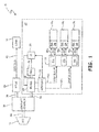
- FIG. 1 is a block diagram illustrating electric system 10 for powering loads 12 and engine accessories 14a-14c.
- Electric system 10 includes loads 12, prime mover 16, gearbox 18, wound field synchronous generator (WFSG) 20, and engine accessories electric system 22.
- Engine accessories electric system 22 includes engine accessories 14a-14c, flux regulated permanent magnet generator (FRPMG) 24, permanent magnet generator (PMG) 26, voltage regulator 28, sensors 30, and load management and distribution (LMD) module 32.
- FRPMG flux regulated permanent magnet generator
- PMG permanent magnet generator
- LMD load management and distribution
- Prime mover 16 is utilized to drive both WFSG 20 and FRPMG 24 through gearbox 18.
- prime mover 16 may be implemented as any prime mover.
- Gearbox 18 may be, for example, an aircraft speed reducing gearbox.
- Shaft 36 is driven by gearbox 18 to drive WFSG 20 and shaft 38 is driven by gearbox 18 to drive FRPMG 24.
- Constant voltage variable frequency (CVVF) power is provided from WFSG 20 to loads 12 on CVVF bus 40.
- Loads 12 are any loads and may be, for example, loads onboard an aircraft carrying prime mover 16.
- VVVF Variable voltage variable frequency
- LMD module 32 includes solid state power controllers (SSPCs) 44a-44c.
- Engine accessories 14a-14c include respective induction motors (IMs) 46a-46c. Power is provided to IMs 46a-46c through respective redundant power inputs 48a-48c and 50a-50c.
- Engine accessories 14a-14c are any accessories that are driven by electromechanical means, such as, for example, fuel pumps or oil pumps. Although illustrated as three engine accessories 14a-14c, system 10 may include any number of engine accessories.
- Voltage regulator 28 is configured to control the output voltage of FRPMG 24 provided on WVF buses 42a and 42b.
- FRPMG 24 allows for active electromagnetic regulation of magnetic flux present in FRPMG 24 to control electrical power generation without dependence upon control of the rotational speed of the components of FRPMG 24.
- Voltage regulator 28 controls the output of FRPMG 24 using any desirable control method.
- voltage regulator 28 may apply a control current to control coils of FRPMG 24. The application of the control current magnetically saturates shunts to reduce shunting of the air gap magnetic flux. This increases the magnetic flux linkage between permanent magnets of FRPMG 24 and stator coils of FRPMG 24, which increases the generated electromagnetic force (EMF) and electromagnetic torque to control the output voltage.
- EMF electromagnetic force
- PMG 26 provides power to voltage regulator 28 and may be driven by the same shaft 38 as FRPMG 24.
- PMG 26 is any generator capable of providing power to voltage regulator 28 based upon the mechanical energy transferred through shaft 38.
- voltage regulator 28 may be powered using any other desirable method.
- Sensors 30 sense, for example, the current and the voltage on WVF buses 42a and 42b.
- Sensors 30 may be implemented as, for example, any current sensors and/or voltage sensors.
- the frequency and voltage on WVF buses 42a and 42b are adjusted by voltage regulator 28 based upon the sensed values from sensors 30.
- Voltage regulator 28 controls FRPMG 24 to maintain, for example, a constant voltage-to-frequency (V/Hz) ratio on VWF buses 42a and 42b.
- Voltage regulator 28 is configured to maintain the constant V/Hz ratio at any desired value based upon the characteristics of prime mover 16 and engine accessories 14a-14c.
- Power having a constant V/Hz ratio on VVVF buses 42a and 42b may utilized to drive IMs 46a-46c of engine accessories 14a-14c.
- the torque for an IM may be determined based upon the V/Hz ratio of the power provided on VVVF buses 42a and 42b to the IM 46a-46c. Failure to maintain a constant V/Hz ratio may affect motor torque, temperature, speed, and current draw. If the air-gap flux of the induction motor is maintained constant by controlling the V/Hz ratio, the motor can deliver its rated torque. Therefore, it is desirable to maintain a constant V/Hz ratio when supplying power to a motor to maintain a rated motor torque.
- Past systems utilized motor controllers to control power from constant voltage variable frequency buses to the induction motors of aircraft accessories to maintain rated motor torque.
- FRPMG 24 By controlling FRPMG 24 to output a constant V/Hz ratio on VVVF buses 42a and 42b, the motor controllers of past systems may be eliminated from engine accessories electric system 22. This reduces the size and weight of engine accessories electric system 22 and increases the efficiency of system 10.
- Variation in speed of prime mover 16 causes a proportional variation of the output voltage and frequency of FRPMG 24.
- FRPMG 24 and IMs 46a-46c such that the output voltage and frequency of FRPMG maintains the air-gap flux of IMs 46a-46c at a desired value during steady-state operation, the speed of IMs 46a-46c can be controlled closely proportional to the speed of prime mover 16. As the speed of prime mover 16 increases, the stator voltage and frequency of IMs 46a-46c proportionally increases, maintaining a constant V/Hz ratio.
- LMD module 32 receives the VVVF power with the constant V/Hz ratio from FRPMG 24 on VVVF buses 42a and 42b. Each accessory 14a-14c receives power from redundant respective power lines 48a-48c and 50a-50c. LMD module 32 includes SSPCs 44a-44c to control power to accessories 14a-14c. Redundant power is provided on power lines 48a-48c and 50a-50c to provide fault control and isolation. IMs 46a-46c may receive, for example, three-phase inputs to drive the motor. In this case, each redundant line 48a-48c an 50a-50c includes three phase lines.
- LMD module 32 may control, for example, SSPCs 44a-44c to terminate and/or isolate the faulty load.
- LMD module 32 may be implemented as any electronic or electromechanical circuit, and may include, for example, analog and/or digital components.
- FIG. 2 is a flowchart illustrating method 60 of controlling FRPMG 24 for providing power to engine accessories 14a-14c.
- prime mover 16 drives FRPMG 24 through gearbox 18.
- PMG 26 is also driven by prime mover 16 to provide initial power to voltage regulator 28.
- voltage and current are sensed by sensors 30 on VVVF buses 42a and 42b and the sensed values are provided to voltage regulator 28.
- voltage regulator 28 controls FRPMG 24 to output a constant V/Hz ratio.
- the constant V/Hz ratio is any desirable value based upon the speed of gas turbine engine and IMs 46a-46c.
- power is provided from FRPMG 24 at a constant V/Hz ratio to IMs 46a-46c to drive accessories 14a-14c.
- An electric system includes a flux regulated permanent magnet generator configured to provide power for an accessory electric system.
- the accessory electric system includes an engine accessory and a voltage regulator.
- the engine accessory includes an induction motor that receives power from the flux regulated permanent magnet generator.
- the voltage regulator is configured to control an output of the flux regulated permanent magnet generator to maintain a constant voltage-to-frequency ratio.
- the electric system of the preceding paragraph can optionally include, additionally and/or alternatively, any one or more of the following features, configurations and/or additional components:
- the accessory electric system further includes a sensor that senses an output condition indicative of the output of the flux regulated permanent magnet generator.
- the voltage regulator controls the output of the flux regulated permanent magnet generator based upon the output condition.
- accessory electric system further includes an auxiliary permanent magnet generator configured to provide power to the voltage regulator.
- the auxiliary permanent magnet generator and the flux regulated permanent magnet generator are driven by a common shaft.
- the sensor comprises a current sensor and a voltage sensor.
- a further embodiment of any of the foregoing electric systems further including a gearbox and a wound field synchronous generator.
- the gearbox drives the wound field synchronous generator through a first shaft, and the gearbox drives the flux regulated permanent magnet generator through a second shaft.
- the accessory electric system further includes first and second power buses connected to provide power from the flux regulated permanent magnet generator to the load management module, and a load management module configured to control power from the flux regulated permanent magnet generator to the first engine accessory.
- accessory electric system further includes a second engine accessory that includes a second induction motor.
- the load management module includes a plurality of solid state power controllers that control power provided from the first and second power buses to the first and second engine accessories.
- a method includes driving, by a gas turbine, a flux regulated permanent magnet generator and providing, by the flux regulated permanent magnet generator, output power to a plurality of engine accessories.
- the output power has a power frequency and a power voltage.
- the method also includes controlling, using a voltage regulator, the power voltage of the flux regulated permanent magnet generator to maintain a constant ratio between the power voltage and the power frequency.
- the method of the preceding paragraph can optionally include, additionally and/or alternatively, any one or more of the following features, configurations and/or additional components:
- a further embodiment of the foregoing method further including driving, by the gas turbine engine, a wound field synchronous generator, and providing, by the wound field synchronous generator, load power to a plurality of aircraft loads.
- a further embodiment of any of the forgoing methods further including driving the plurality of engine accessories using a plurality of induction motors, and controlling the output power from the flux regulated permanent magnet generator to the plurality of induction motors using a plurality of solid state power controllers.
- a further embodiment of any of the forgoing methods further including providing, by an auxiliary permanent magnet generator, power to the voltage regulator.
- driving, by the gas turbine engine, the flux regulated permanent magnet generator comprises driving the flux regulated permanent magnet generator using a gearbox.
- the flux regulated permanent magnet generator and the auxiliary permanent magnet generator are driven by a common shaft.
- a further embodiment of any of the forgoing methods further including sensing a sensed condition of the output power of the flux regulated permanent magnet generator.
- Controlling, using the voltage regulator, the output voltage of the flux regulated permanent magnet generator comprises controlling the output voltage based upon the sensed condition.
Landscapes
- Engineering & Computer Science (AREA)
- Power Engineering (AREA)
- Mechanical Engineering (AREA)
- Control Of Eletrric Generators (AREA)
Abstract
An electric system and method includes a flux regulated permanent magnet generator 24 configured to provide power for an accessory electric system 22. The accessory electric system includes an engine accessory 14 and a voltage regulator 28. The engine accessory includes an induction motor 46 that receives power from the flux regulated permanent magnet generator. The voltage regulator is configured to control an output of the flux regulated permanent magnet generator to maintain a constant voltage-to-frequency ratio.
Description
- The present invention relates generally to more-electric engines (MEE) and particularly to an electric system architecture for a MEE.
- Electrical system architecture for gas turbine engines, such as the one described in
U.S. Patent No. 8,237,416 , have recently been developed to provide electrical power to loads associated with, for example, an aircraft carrying the gas turbine engine. These loads include, for example, motor driven fuel pumps and oil pumps. In order to achieve fault tolerant operation for flight critical functions, the electrical system architecture may include a dual direct current (DC) or alternating current (AC) bus that powers multiple dual-redundant motor controllers. These motor controllers drive permanent magnet motors with, for example, dual stator windings and may include switching mode power converters. In order to meet stringent conducted and radiated emissions requirements, electromagnetic interference (EMI) filters are often implemented to attenuate the noise created by these switching mode power converters. The weight and size of the motor controllers is aggravated by the need for these EMI filters. There is a need to improve electrical system architecture for gas turbine MEEs to reduce or eliminate the need for complex motor controllers in order to reduce the size and weight of the MEE electrical system. - An electric system includes a flux regulated permanent magnet generator configured to provide power for an accessory electric system. The accessory electric system includes an engine accessory and a voltage regulator. The engine accessory includes an induction motor that receives power from the flux regulated permanent magnet generator. The voltage regulator is configured to control an output of the flux regulated permanent magnet generator to maintain a constant voltage-to-frequency ratio.
- A method includes driving, by a gas turbine, a flux regulated permanent magnet generator and providing, by the flux regulated permanent magnet generator, output power to a plurality of engine accessories. The output power has a power frequency and a power voltage. The method also includes controlling, using a voltage regulator, the power voltage of the flux regulated permanent magnet generator to maintain a constant ratio between the power voltage and the power frequency.
-
-
FIG. 1 is a block diagram that illustrates an electric system for powering loads and engine accessories. -
FIG. 2 is a flowchart illustrating a method of controlling a flux regulated permanent magnet generator for providing power to engine accessories. - A system and method is disclosed herein that provides power for both aircraft loads and engine accessories. The system includes two electrical generators driven by, for example, an aircraft speed reducing gearbox. The generators include a wound field synchronous generator (WFSG) and a flux regulated permanent magnet generator (FRPMG). The WFSG provides constant voltage variable frequency (CWF) power to, for example, aircraft loads. The FRPMG provides two variable voltage variable frequency (WVF) buses to power, for example, induction motors for engine accessories. A voltage regulator may be utilized to control the output voltage of the FRPMG based upon sensed voltage and current on the VWF buses. In this way, a constant voltage-to-frequency (V/Hz) ratio may be maintained on the VWF buses, eliminating the need for motor controllers for each of the induction motors. By eliminating the need for motor controllers, the weight of the system may be reduced and the overall efficiency of the electrical system may be increased.
-
FIG. 1 is a block diagram illustratingelectric system 10 for poweringloads 12 andengine accessories 14a-14c.Electric system 10 includesloads 12,prime mover 16,gearbox 18, wound field synchronous generator (WFSG) 20, and engine accessorieselectric system 22. Engine accessorieselectric system 22 includesengine accessories 14a-14c, flux regulated permanent magnet generator (FRPMG) 24, permanent magnet generator (PMG) 26,voltage regulator 28,sensors 30, and load management and distribution (LMD)module 32. -
Prime mover 16 is utilized to drive both WFSG 20 and FRPMG 24 throughgearbox 18. Although illustrated inFIG. 1 as a gas turbine engine,prime mover 16 may be implemented as any prime mover. Gearbox 18 may be, for example, an aircraft speed reducing gearbox. Shaft 36 is driven bygearbox 18 to drive WFSG 20 andshaft 38 is driven bygearbox 18 to drive FRPMG 24. Constant voltage variable frequency (CVVF) power is provided from WFSG 20 to loads 12 onCVVF bus 40.Loads 12 are any loads and may be, for example, loads onboard an aircraft carryingprime mover 16. Variable voltage variable frequency (VVVF) power is provided from FRPMG 24 toLMD module 32 onVVVF buses FIG. 1 ,LMD module 32 includes solid state power controllers (SSPCs) 44a-44c.Engine accessories 14a-14c include respective induction motors (IMs) 46a-46c. Power is provided to IMs 46a-46c through respectiveredundant power inputs 48a-48c and 50a-50c.Engine accessories 14a-14c are any accessories that are driven by electromechanical means, such as, for example, fuel pumps or oil pumps. Although illustrated as threeengine accessories 14a-14c,system 10 may include any number of engine accessories. -
Voltage regulator 28 is configured to control the output voltage ofFRPMG 24 provided onWVF buses Voltage regulator 28 controls the output of FRPMG 24 using any desirable control method. For example, in an embodiment,voltage regulator 28 may apply a control current to control coils ofFRPMG 24. The application of the control current magnetically saturates shunts to reduce shunting of the air gap magnetic flux. This increases the magnetic flux linkage between permanent magnets ofFRPMG 24 and stator coils ofFRPMG 24, which increases the generated electromagnetic force (EMF) and electromagnetic torque to control the output voltage. - In the embodiment illustrated in
FIG. 1 , PMG 26 provides power tovoltage regulator 28 and may be driven by thesame shaft 38 asFRPMG 24.PMG 26 is any generator capable of providing power tovoltage regulator 28 based upon the mechanical energy transferred throughshaft 38. In other embodiments,voltage regulator 28 may be powered using any other desirable method.Sensors 30 sense, for example, the current and the voltage onWVF buses Sensors 30 may be implemented as, for example, any current sensors and/or voltage sensors. The frequency and voltage onWVF buses voltage regulator 28 based upon the sensed values fromsensors 30.Voltage regulator 28 controlsFRPMG 24 to maintain, for example, a constant voltage-to-frequency (V/Hz) ratio onVWF buses Voltage regulator 28 is configured to maintain the constant V/Hz ratio at any desired value based upon the characteristics ofprime mover 16 andengine accessories 14a-14c. - Power having a constant V/Hz ratio on
VVVF buses engine accessories 14a-14c. The torque for an IM may be determined based upon the V/Hz ratio of the power provided onVVVF buses VVVF buses electric system 22. This reduces the size and weight of engine accessorieselectric system 22 and increases the efficiency ofsystem 10. - Variation in speed of
prime mover 16 causes a proportional variation of the output voltage and frequency ofFRPMG 24. By designingFRPMG 24 and IMs 46a-46c such that the output voltage and frequency of FRPMG maintains the air-gap flux of IMs 46a-46c at a desired value during steady-state operation, the speed of IMs 46a-46c can be controlled closely proportional to the speed ofprime mover 16. As the speed ofprime mover 16 increases, the stator voltage and frequency of IMs 46a-46c proportionally increases, maintaining a constant V/Hz ratio. -
LMD module 32 receives the VVVF power with the constant V/Hz ratio fromFRPMG 24 onVVVF buses respective power lines 48a-48c and 50a-50c.LMD module 32 includes SSPCs 44a-44c to control power toaccessories 14a-14c. Redundant power is provided onpower lines 48a-48c and 50a-50c to provide fault control and isolation. IMs 46a-46c may receive, for example, three-phase inputs to drive the motor. In this case, eachredundant line 48a-48c an 50a-50c includes three phase lines. In the event of a fault,LMD module 32 may control, for example,SSPCs 44a-44c to terminate and/or isolate the faulty load.LMD module 32 may be implemented as any electronic or electromechanical circuit, and may include, for example, analog and/or digital components. - With continued reference to
FIG. 1 ,FIG. 2 is aflowchart illustrating method 60 of controllingFRPMG 24 for providing power toengine accessories 14a-14c. Atstep 62,prime mover 16 drives FRPMG 24 throughgearbox 18.PMG 26 is also driven byprime mover 16 to provide initial power tovoltage regulator 28. Atstep 64, voltage and current are sensed bysensors 30 onVVVF buses voltage regulator 28. Atstep 66,voltage regulator 28 controls FRPMG 24 to output a constant V/Hz ratio. The constant V/Hz ratio is any desirable value based upon the speed of gas turbine engine and IMs 46a-46c. Atstep 68, power is provided fromFRPMG 24 at a constant V/Hz ratio to IMs 46a-46c to driveaccessories 14a-14c. - The following are non-exclusive descriptions of possible embodiments of the present invention.
- An electric system includes a flux regulated permanent magnet generator configured to provide power for an accessory electric system. The accessory electric system includes an engine accessory and a voltage regulator. The engine accessory includes an induction motor that receives power from the flux regulated permanent magnet generator. The voltage regulator is configured to control an output of the flux regulated permanent magnet generator to maintain a constant voltage-to-frequency ratio.
- The electric system of the preceding paragraph can optionally include, additionally and/or alternatively, any one or more of the following features, configurations and/or additional components:
- A further embodiment of the foregoing electric system, wherein the accessory electric system further includes a sensor that senses an output condition indicative of the output of the flux regulated permanent magnet generator. The voltage regulator controls the output of the flux regulated permanent magnet generator based upon the output condition.
- A further embodiment of any of the foregoing electric systems, wherein the accessory electric system further includes an auxiliary permanent magnet generator configured to provide power to the voltage regulator. The auxiliary permanent magnet generator and the flux regulated permanent magnet generator are driven by a common shaft.
- A further embodiment of any of the foregoing electric systems, wherein the sensor comprises a current sensor and a voltage sensor.
- A further embodiment of any of the foregoing electric systems, further including a gearbox and a wound field synchronous generator. The gearbox drives the wound field synchronous generator through a first shaft, and the gearbox drives the flux regulated permanent magnet generator through a second shaft.
- A further embodiment of any of the foregoing electric systems, wherein the flux regulated permanent magnet generator and the wound field synchronous generator are driven by a gas turbine engine.
- A further embodiment of any of the foregoing electric systems, wherein the accessory electric system further includes first and second power buses connected to provide power from the flux regulated permanent magnet generator to the load management module, and a load management module configured to control power from the flux regulated permanent magnet generator to the first engine accessory.
- A further embodiment of any of the foregoing electric systems, wherein the accessory electric system further includes a second engine accessory that includes a second induction motor.
- A further embodiment of any of the foregoing electric systems, wherein the load management module includes a plurality of solid state power controllers that control power provided from the first and second power buses to the first and second engine accessories.
- A method includes driving, by a gas turbine, a flux regulated permanent magnet generator and providing, by the flux regulated permanent magnet generator, output power to a plurality of engine accessories. The output power has a power frequency and a power voltage. The method also includes controlling, using a voltage regulator, the power voltage of the flux regulated permanent magnet generator to maintain a constant ratio between the power voltage and the power frequency.
- The method of the preceding paragraph can optionally include, additionally and/or alternatively, any one or more of the following features, configurations and/or additional components:
- A further embodiment of the foregoing method, further including driving, by the gas turbine engine, a wound field synchronous generator, and providing, by the wound field synchronous generator, load power to a plurality of aircraft loads.
- A further embodiment of any of the forgoing methods, further including driving the plurality of engine accessories using a plurality of induction motors, and controlling the output power from the flux regulated permanent magnet generator to the plurality of induction motors using a plurality of solid state power controllers.
- A further embodiment of any of the forgoing methods, further including providing, by an auxiliary permanent magnet generator, power to the voltage regulator.
- A further embodiment of any of the forgoing methods, wherein driving, by the gas turbine engine, the flux regulated permanent magnet generator comprises driving the flux regulated permanent magnet generator using a gearbox. The flux regulated permanent magnet generator and the auxiliary permanent magnet generator are driven by a common shaft.
- A further embodiment of any of the forgoing methods, further including sensing a sensed condition of the output power of the flux regulated permanent magnet generator. Controlling, using the voltage regulator, the output voltage of the flux regulated permanent magnet generator comprises controlling the output voltage based upon the sensed condition.
- While the invention has been described with reference to an exemplary embodiment(s), it will be understood by those skilled in the art that various changes may be made and equivalents may be substituted for elements thereof without departing from the scope of the invention. In addition, many modifications may be made to adapt a particular situation or material to the teachings of the invention without departing from the essential scope thereof. Therefore, it is intended that the invention not be limited to the particular embodiment(s) disclosed, but that the invention will include all embodiments falling within the scope of the appended claims.
Claims (15)
- An electric system comprising:a flux regulated permanent magnet generator (24) configured to provide power for an accessory electric system (22), wherein the accessory electric system comprises:a first engine accessory (14a) that includes a first induction motor (46a), wherein the first induction motor receives power from the flux regulated permanent magnet generator; anda voltage regulator (28) configured to control an output of the flux regulated permanent magnet generator to maintain a constant voltage-to-frequency ratio.
- The electric system of claim 1, wherein the accessory electric system further comprises:a sensor (30) that senses an output condition indicative of the output of the flux regulated permanent magnet generator, wherein the voltage regulator controls the output of the flux regulated permanent magnet generator based upon the output condition.
- The electric system of claim 2, wherein the accessory electric system further comprises:an auxiliary permanent magnet generator (26) configured to provide power to the voltage regulator, wherein the auxiliary permanent magnet generator and the flux regulated permanent magnet generator are driven by a common shaft.
- The electric system of claim 2, wherein the sensor comprises a current sensor and a voltage sensor.
- The electric system of any preceding claim, further comprising:a gearbox (18); anda wound field synchronous generator (20), wherein the gearbox drives the wound field synchronous generator through a first shaft, and wherein the gearbox drives the flux regulated permanent magnet generator through a second shaft.
- The electric system of claim 5, wherein the flux regulated permanent magnet generator and the wound field synchronous generator are driven by a gas turbine engine (16).
- The electric system of any preceding claim, wherein the accessory electric system further comprises:first and second power buses (42a, 42b) connected to provide power from the flux regulated permanent magnet generator to the load management module; anda load management module (32) configured to control power from the flux regulated permanent magnet generator to the first engine accessory.
- The electric system of claim 7, wherein the accessory electric system further comprises a second engine accessory (14b) that includes a second induction motor (46a).
- The electric system of claim 8, wherein the load management module includes a plurality of solid state power controllers (44) that control power provided from the first and second power buses to the first and second engine accessories.
- A method comprising:driving, by a gas turbine, a flux regulated permanent magnet generator;providing, by the flux regulated permanent magnet generator, output power to a plurality of engine accessories, wherein the output power has a power frequency and a power voltage; andcontrolling, using a voltage regulator, the power voltage of the flux regulated permanent magnet generator to maintain a constant ratio between the power voltage and the power frequency.
- The method of claim 10, further comprising:driving, by the gas turbine engine, a wound field synchronous generator; andproviding, by the wound field synchronous generator, load power to a plurality of aircraft loads.
- The method of claim 10, further comprising:driving the plurality of engine accessories using a plurality of induction motors; andcontrolling the output power from the flux regulated permanent magnet generator to the plurality of induction motors using a plurality of solid state power controllers.
- The method of claim 10, further comprising:providing, by an auxiliary permanent magnet generator, power to the voltage regulator.
- The method of claim 13, wherein driving, by the gas turbine engine, the flux regulated permanent magnet generator comprises driving the flux regulated permanent magnet generator using a gearbox, wherein the flux regulated permanent magnet generator and the auxiliary permanent magnet generator are driven by a common shaft.
- The method of any of claims 10 to 14, further comprising:sensing a sensed condition of the output power of the flux regulated permanent magnet generator;wherein controlling, using the voltage regulator, the output voltage of the flux regulated permanent magnet generator comprises controlling the output voltage based upon the sensed condition.
Applications Claiming Priority (1)
| Application Number | Priority Date | Filing Date | Title |
|---|---|---|---|
| US14/461,927 US9573539B2 (en) | 2014-08-18 | 2014-08-18 | Electric system architecture for more-electric engine accessories |
Publications (1)
| Publication Number | Publication Date |
|---|---|
| EP2988413A1 true EP2988413A1 (en) | 2016-02-24 |
Family
ID=53836494
Family Applications (1)
| Application Number | Title | Priority Date | Filing Date |
|---|---|---|---|
| EP15180990.2A Withdrawn EP2988413A1 (en) | 2014-08-18 | 2015-08-13 | Electric system architecture for more-electric engine accessories |
Country Status (2)
| Country | Link |
|---|---|
| US (1) | US9573539B2 (en) |
| EP (1) | EP2988413A1 (en) |
Cited By (2)
| Publication number | Priority date | Publication date | Assignee | Title |
|---|---|---|---|---|
| CN105790602A (en) * | 2016-04-17 | 2016-07-20 | 合肥博雷电气有限公司 | Vehicle-mounted DC voltage-stabilizing power supply |
| CN108111091A (en) * | 2017-12-28 | 2018-06-01 | 国网北京市电力公司 | Reduce the method, apparatus and storage medium of the total losses of asynchronous motor |
Families Citing this family (10)
| Publication number | Priority date | Publication date | Assignee | Title |
|---|---|---|---|---|
| US10730633B2 (en) | 2016-11-22 | 2020-08-04 | Honeywell International Inc. | Hybrid electric aircraft propulsion system with motors using induction effect |
| US10491145B2 (en) | 2017-08-11 | 2019-11-26 | Rolls-Royce North American Technologies Inc. | Gas turbine generator speed DC to DC converter control system |
| US10483887B2 (en) | 2017-08-11 | 2019-11-19 | Rolls-Royce North American Technologies, Inc. | Gas turbine generator temperature DC to DC converter control system |
| US10476417B2 (en) * | 2017-08-11 | 2019-11-12 | Rolls-Royce North American Technologies Inc. | Gas turbine generator torque DC to DC converter control system |
| CN108631675A (en) * | 2018-05-11 | 2018-10-09 | 北京理工大学 | A kind of optimization method reducing electromagnetic consumable in motor low speed high torque area |
| US11267575B2 (en) | 2019-10-18 | 2022-03-08 | Hamilton Sundstrand Corporation | Equalizing wearing of two or more electrical power generators of an aircraft |
| US12031479B2 (en) * | 2020-08-31 | 2024-07-09 | General Electric Company | Hybrid electric propulsion system load share |
| US11873081B2 (en) | 2021-06-09 | 2024-01-16 | Textron Innovations Inc. | Supplemental engine power control |
| US12077308B2 (en) | 2022-04-14 | 2024-09-03 | Textron Innovations Inc. | Supplemental engine transition control |
| US12054245B2 (en) * | 2022-07-18 | 2024-08-06 | Textron Innovations Inc. | Optimizing usage of supplemental engine power |
Citations (5)
| Publication number | Priority date | Publication date | Assignee | Title |
|---|---|---|---|---|
| US20040090204A1 (en) * | 2002-11-12 | 2004-05-13 | Honeywell International Inc. | Electric motor driven engine accessories |
| US20100170983A1 (en) * | 2009-01-08 | 2010-07-08 | Airbus Operations (Societe Par Actions Simplifiee) | Flight control system for an aircraft |
| US8237416B2 (en) | 2008-12-09 | 2012-08-07 | Hamilton Sundstrand Corporation | More electric engine with regulated permanent magnet machines |
| EP2670045A2 (en) * | 2012-06-01 | 2013-12-04 | Hamilton Sundstrand Corporation | Dual generator system |
| EP2677618A2 (en) * | 2012-06-01 | 2013-12-25 | Hamilton Sundstrand Corporation | Electrical power generation and distribution fault management system for a vehicle |
Family Cites Families (9)
| Publication number | Priority date | Publication date | Assignee | Title |
|---|---|---|---|---|
| US4663581A (en) * | 1984-10-31 | 1987-05-05 | Sundstrand Corporation | Voltage regulated permanent magnet generator system |
| FR2911917B1 (en) * | 2007-01-31 | 2013-05-17 | Hispano Suiza Sa | DISTRIBUTED GAS TURBINE GENERATOR-STARTER ARCHITECTURE |
| US7952220B2 (en) | 2007-09-21 | 2011-05-31 | Hamilton Sundstrand Corporation | Generator for gas turbine engine having main DC bus accessory AC bus |
| US7859231B2 (en) * | 2008-04-02 | 2010-12-28 | Hamilton Sundstrand Corporation | Permanent magnet electric generator with variable magnet flux excitation |
| US7852049B2 (en) * | 2008-04-20 | 2010-12-14 | Hamilton Sundstrand Corporation | Dual channel power generation system |
| US8085003B2 (en) * | 2009-01-19 | 2011-12-27 | Hamilton Sundstrand Corporation | Voltage regulated permanent magnet generator |
| US8358111B2 (en) * | 2009-12-03 | 2013-01-22 | Hamilton Sundstrand Corporation | Architecture for dual source electric power generating system |
| US8344544B2 (en) * | 2010-05-19 | 2013-01-01 | Hamilton Sundstrand Corporation | Bus-tie SSPCS for DC power distribution system |
| US8829707B2 (en) * | 2010-07-15 | 2014-09-09 | Hamilton Sundstrand Corporation | Methods for aircraft emergency power management |
-
2014
- 2014-08-18 US US14/461,927 patent/US9573539B2/en not_active Expired - Fee Related
-
2015
- 2015-08-13 EP EP15180990.2A patent/EP2988413A1/en not_active Withdrawn
Patent Citations (5)
| Publication number | Priority date | Publication date | Assignee | Title |
|---|---|---|---|---|
| US20040090204A1 (en) * | 2002-11-12 | 2004-05-13 | Honeywell International Inc. | Electric motor driven engine accessories |
| US8237416B2 (en) | 2008-12-09 | 2012-08-07 | Hamilton Sundstrand Corporation | More electric engine with regulated permanent magnet machines |
| US20100170983A1 (en) * | 2009-01-08 | 2010-07-08 | Airbus Operations (Societe Par Actions Simplifiee) | Flight control system for an aircraft |
| EP2670045A2 (en) * | 2012-06-01 | 2013-12-04 | Hamilton Sundstrand Corporation | Dual generator system |
| EP2677618A2 (en) * | 2012-06-01 | 2013-12-25 | Hamilton Sundstrand Corporation | Electrical power generation and distribution fault management system for a vehicle |
Cited By (3)
| Publication number | Priority date | Publication date | Assignee | Title |
|---|---|---|---|---|
| CN105790602A (en) * | 2016-04-17 | 2016-07-20 | 合肥博雷电气有限公司 | Vehicle-mounted DC voltage-stabilizing power supply |
| CN108111091A (en) * | 2017-12-28 | 2018-06-01 | 国网北京市电力公司 | Reduce the method, apparatus and storage medium of the total losses of asynchronous motor |
| CN108111091B (en) * | 2017-12-28 | 2020-08-11 | 国网北京市电力公司 | Method, device and storage medium for reducing total loss of asynchronous motor |
Also Published As
| Publication number | Publication date |
|---|---|
| US20160046247A1 (en) | 2016-02-18 |
| US9573539B2 (en) | 2017-02-21 |
Similar Documents
| Publication | Publication Date | Title |
|---|---|---|
| US9573539B2 (en) | Electric system architecture for more-electric engine accessories | |
| US10378445B2 (en) | Gas turbine engine fuel system | |
| Avery et al. | Electrical generation and distribution for the more electric aircraft | |
| EP2330723B1 (en) | Transverse regulated flux machine | |
| US7514806B2 (en) | Engine start system with quadrature AC excitation | |
| JP5596024B2 (en) | Synchronous generator | |
| EP2801719A1 (en) | Aircraft electrical system | |
| EP3375981A1 (en) | Variable speed ac bus powered tail cone boundary layer ingestion thruster | |
| EP3012438A1 (en) | Gas turbine engine fuel system | |
| CN104426444B (en) | A kind of constant frequency starter/generator for turbogenerator | |
| EP2779421B1 (en) | Integrated starter generator | |
| EP2040370B1 (en) | Generator for gas turbine engine having main DC bus and accessory AC bus | |
| CA2788303A1 (en) | Method and apparatus for extracting electrical power from a gas turbine engine | |
| US8823334B2 (en) | Method for starting an electric motor | |
| US10113525B2 (en) | Method for controlling a starter-generator | |
| US20170237383A1 (en) | Method and power converter unit for operating a generator | |
| EP2071692B1 (en) | Motor drive architecture for high frequency AC bus | |
| US9628008B1 (en) | Method and generator control unit for configuring an output from a generator | |
| EP3706307B1 (en) | Series hybrid architectures using compounded doubly fed machines | |
| EP3240184B1 (en) | Method for implementing a pmg varaible speed constant frequency generating system and a control processor | |
| EP3096448B1 (en) | Wound-field generator including electrically isolated engine alternator | |
| US12428998B2 (en) | Aircraft engine start using multiple common motor controllers | |
| Silveira et al. | Voltage control in starter/generator SRM based systems | |
| CN120720125A (en) | Method and system for rapidly starting combustion engines in a multi-engine aircraft |
Legal Events
| Date | Code | Title | Description |
|---|---|---|---|
| PUAI | Public reference made under article 153(3) epc to a published international application that has entered the european phase |
Free format text: ORIGINAL CODE: 0009012 |
|
| AK | Designated contracting states |
Kind code of ref document: A1 Designated state(s): AL AT BE BG CH CY CZ DE DK EE ES FI FR GB GR HR HU IE IS IT LI LT LU LV MC MK MT NL NO PL PT RO RS SE SI SK SM TR |
|
| AX | Request for extension of the european patent |
Extension state: BA ME |
|
| STAA | Information on the status of an ep patent application or granted ep patent |
Free format text: STATUS: THE APPLICATION IS DEEMED TO BE WITHDRAWN |
|
| 18D | Application deemed to be withdrawn |
Effective date: 20160825 |