EP2988412A1 - System and method for improving response time of a braking unit - Google Patents
System and method for improving response time of a braking unit Download PDFInfo
- Publication number
- EP2988412A1 EP2988412A1 EP15177889.1A EP15177889A EP2988412A1 EP 2988412 A1 EP2988412 A1 EP 2988412A1 EP 15177889 A EP15177889 A EP 15177889A EP 2988412 A1 EP2988412 A1 EP 2988412A1
- Authority
- EP
- European Patent Office
- Prior art keywords
- capacitor
- voltage level
- voltage
- converter
- level
- Prior art date
- Legal status (The legal status is an assumption and is not a legal conclusion. Google has not performed a legal analysis and makes no representation as to the accuracy of the status listed.)
- Granted
Links
- 238000000034 method Methods 0.000 title claims description 21
- 230000004044 response Effects 0.000 title description 12
- 239000003990 capacitor Substances 0.000 claims abstract description 86
- 238000010248 power generation Methods 0.000 claims description 14
- 230000000977 initiatory effect Effects 0.000 claims 1
- 238000010586 diagram Methods 0.000 description 4
- 230000001133 acceleration Effects 0.000 description 2
- 230000008859 change Effects 0.000 description 2
- 230000004048 modification Effects 0.000 description 2
- 238000012986 modification Methods 0.000 description 2
- 230000001105 regulatory effect Effects 0.000 description 2
- 230000005540 biological transmission Effects 0.000 description 1
- 238000004146 energy storage Methods 0.000 description 1
- 230000001939 inductive effect Effects 0.000 description 1
- 230000009467 reduction Effects 0.000 description 1
- 230000001360 synchronised effect Effects 0.000 description 1
Images


Classifications
-
- H—ELECTRICITY
- H02—GENERATION; CONVERSION OR DISTRIBUTION OF ELECTRIC POWER
- H02P—CONTROL OR REGULATION OF ELECTRIC MOTORS, ELECTRIC GENERATORS OR DYNAMO-ELECTRIC CONVERTERS; CONTROLLING TRANSFORMERS, REACTORS OR CHOKE COILS
- H02P9/00—Arrangements for controlling electric generators for the purpose of obtaining a desired output
- H02P9/02—Details of the control
-
- H—ELECTRICITY
- H02—GENERATION; CONVERSION OR DISTRIBUTION OF ELECTRIC POWER
- H02P—CONTROL OR REGULATION OF ELECTRIC MOTORS, ELECTRIC GENERATORS OR DYNAMO-ELECTRIC CONVERTERS; CONTROLLING TRANSFORMERS, REACTORS OR CHOKE COILS
- H02P15/00—Arrangements for controlling dynamo-electric brakes or clutches
-
- H—ELECTRICITY
- H02—GENERATION; CONVERSION OR DISTRIBUTION OF ELECTRIC POWER
- H02P—CONTROL OR REGULATION OF ELECTRIC MOTORS, ELECTRIC GENERATORS OR DYNAMO-ELECTRIC CONVERTERS; CONTROLLING TRANSFORMERS, REACTORS OR CHOKE COILS
- H02P3/00—Arrangements for stopping or slowing electric motors, generators, or dynamo-electric converters
- H02P3/02—Details of stopping control
- H02P3/04—Means for stopping or slowing by a separate brake, e.g. friction brake or eddy-current brake
Definitions
- the disclosure relates generally to a power generation system and more specifically to improved response time of a braking unit in a power generation system.
- the braking unit includes one or more coils that are disposed proximate to the rotor, and, when a voltage is applied to these coils, electromagnetic braking force is induced on the rotor such that the speed of the rotor is controlled accordingly. Due to the inductive nature of the coils, the rate of change in the electrical current in the coils is limited by the applied voltage and may require a longer than desired braking response time. To improve the response time, a higher voltage power source may be coupled to the coils. However, such power source would increase the cost and size of the braking unit and may be impractical.
- a braking system includes a converter, a capacitor coupled to an output of the converter, a bridge coupled in parallel to the capacitor, at least one inductor coupled to the bridge, an electrically conductive disc disposed proximate to the at least one inductor, and a switching unit controller for commanding the converter to convert a level of voltage supplied therefrom from a first voltage level to a second voltage level and thereby increase energy stored in the capacitor, and, upon receiving a brake command, commanding the bridge to ramp-up electrical current in the at least one inductor so as to induce an electromagnetic force on the electrically conductive disc.
- a method includes commanding a converter to increase a level of voltage supplied therefrom from a first voltage level to a second voltage level and thereby increase energy stored in a capacitor coupled in parallel between the converter and a bridge.
- the method further includes, upon receiving a brake command, causing the bridge to ramp-up electrical current in at least one inductor so as to induce an electromagnetic force on an electrically conductive disc.
- a power generation system includes an electrically conductive disc coupled to a rotatable shaft, at least one inductor disposed proximate to the electrically conductive disc, a power source, and a switching unit coupled between the power source and the at least one inductor.
- the switching unit comprises a converter, a capacitor coupled to an output of the converter, a bridge coupled in parallel to the capacitor, and a switching unit controller for commanding the converter to convert a level of voltage supplied therefrom from a first voltage level to a second voltage level and thereby increase energy stored in the capacitor, and, upon receiving a brake command, commanding the bridge to ramp-up electrical current in the at least one inductor so as to induce an electromagnetic force on the electrically conductive disc.
- speed of a rotatable shaft may be controlled within a desired time period, which in turn improves LVRT (low voltage ride through) or FRT (fault ride through) capabilities in the power generation system.
- LVRT low voltage ride through
- FRT fault ride through
- a power generation system 100 having a braking unit in accordance with aspects of the present disclosure, is depicted.
- the power generation system is typically used to convert mechanical power into electrical power.
- the kinetic energy of wind passing across a wind turbine is converted into mechanical power.
- mechanical power may be generated from a gas engine. This mechanical power is in turn used to generate electrical power.
- the power generation system includes a prime mover 102, a rotatable shaft 104, an electrically conductive disc 106, a generator 108, and a braking unit 110.
- the prime mover 102 is mechanically coupled to the power generator 108 through the rotatable shaft 104.
- the rotatable shaft 104 is typically used to convey mechanical power from the prime mover 102 to the power generator 108.
- the mechanical power produced at the prime mover 102 may be used to rotate the rotatable shaft 104 at a predetermined speed.
- This rotation of the rotatable shaft 104 in turn rotates a rotor (not shown) of the generator 108 to generate electrical power.
- the generated electrical power at the generator 108 may be transferred to a power grid 112.
- the electrically conductive disc 106 is rigidly coupled to the rotatable shaft 104 to control the rotational speed of the rotatable shaft 104.
- the braking unit 110 may receive one or more command signals from the power generation system 100.
- the one or more command signals may include or result from one or more status signals received from the power generation system 100.
- the status signals may be representative of a rotational speed of the rotatable shaft 104, a voltage in the power grid 112, a current at the power generator 108, a mechanical power produced by a prime mover 102, a rotor angle of the power generator 108, an electrical power produced by the power generator 108 or combinations thereof.
- the rotational speed of the rotatable shaft 104 may be determined by a speed sensor 124 that is operatively coupled to the rotatable shaft 104.
- the braking unit 110 In response to receiving the command signals, the braking unit 110 induces an electromagnetic force on the electrically conductive disc 106, which in turn regulates or controls the rotational speed of the rotatable shaft 104.
- the speed of the rotatable shaft 104 may be regulated or controlled below a threshold speed value.
- the braking unit 110 may maintain synchronism between the generator 108 and the power grid 112.
- the braking unit 110 includes a braking unit controller 114, an inducting unit 116, a power source 118, and a switching unit 120.
- the inducting unit 116 is coupled to the power source 118 via the switching unit 120 and comprises one or more inductors that are disposed proximate to the electrically conductive disc 106.
- the braking unit controller 114 is coupled to the switching unit 120 and may send a brake command 122 based on one or more command signals received from the power generation system 100.
- the brake command 122 may be sent to the switching unit 120 to control the voltage applied to the inducting unit 116.
- FIG. 2 a more detailed block diagram of the braking unit 110, in accordance with aspects of the present disclosure, is depicted showing the switching unit 120 as comprising a converter 210, a capacitor 212, a bridge 214 and a switching unit controller 216.
- the power source 118 may comprise a low power source, for example, such as a battery having a voltage at a first voltage level.
- the first voltage level may be in a range from about 5V to about 50V.
- the inducting unit 116 is disposed proximate to an electrically conductive disc 106 ( FIG. 1 ) that is rigidly coupled to a rotatable shaft 104 ( FIG. 1 ) of a power generator 108 ( FIG. 1 ).
- the inducting unit 116 comprises one or more inductors that are disposed proximate to the electrically conductive disc 106 to induce an electromagnetic force on the electrically conductive disc 106.
- the one or more inductors may represent electrical coils that are disposed near either side or both sides of the electrically conductive disc 106.
- the switching unit 120 is operatively coupled between the power source 118 and the inducting unit 116 and is used to control the voltage applied to the inducting unit 116 based on a brake command 122 received from the braking unit controller 114.
- the switching unit 120 comprises the converter 210, the capacitor 212, the bridge 214 and the switching unit controller 216.
- the switching unit controller 116 is shown as being included within the switching unit 120 for purposes of example, the switching unit controller 216 may alternatively be integrated within the braking unit controller 114 in some embodiments.
- the converter 210 is coupled between the power source 118 and the capacitor 212. The converter 210 is used to convert the voltage provided by the power source 118 and thereby increase the energy stored in the capacitor 212.
- the bridge 214 is coupled between the capacitor 212 and the inducting unit 116.
- the bridge 214 is used to provide the energy stored in the capacitor 212 to the one of more inductors when the brake command is received by the switching unit controller 216.
- the bridge 214 may further be used to provide energy from the inducting unit 116 to the capacitor 212 when the brake command ceases.
- brake command ceases is intended to cover either (a) the stopping of transmission of the brake command (in the circumstance wherein the switching unit controller continuously receives the command during braking until braking is completed) or (b) a separate command to stop braking (in the circumstance wherein the switching unit controller receives a discrete braking command at one time instance and a separate command to stop braking at a later time instance). Until the brake command ceases, the brake command is referenced as "remaining active.”
- the power source 118 is active, and the converter 210 converts the voltage provided by the power source 118 from the first voltage level to the second voltage level which in one example is in the range from about 200V to about 600V for charging the capacitor 212. In a more specific example, the voltage in the capacitor 212 is increased to about 400V.
- the switching unit controller 216 commands the bridge 214 to provide the voltage in the capacitor 212 to the inducting unit 116 so as to induce the electromagnetic force on the electrically conductive disc 106 ( FIG. 1 ).
- the second voltage in the capacitor 212 is used to provide a fast ramp-up of electrical current in the inducting unit 116.
- the electrical current may be ramped up in the inducting unit 116 within a first time period ranging from about 5 ms to about 50 ms. This fast ramp-up of electrical current in the inducting unit 116 may reduce time to induce the electromagnetic force on the electrically conductive disc 106, and thus improve the response time of the braking unit 110 to induce the electromagnetic force on the electrically conductive disc 106.
- the switching unit controller 216 determines that the energy stored in the capacitor 212 has fallen below a threshold value, the switching unit controller 216 commands the converter 210 to again increase the level of voltage supplied by the power source 118 above the first voltage level.
- the increase is not to the level of the second voltage level but is to a third voltage level that is less than the second voltage level.
- the third voltage level may be in a range from about 50V to about 100V.
- the converter 210 may continuously charge the capacitor 212 at the third voltage level while further braking is needed.
- the capacitor 212 may be continuously charged at the third voltage level so that the electrical current may flow continuously in the inducting unit 116 to compensate the electrical losses in the one or more inductors of the inducting unit 116 and maintain the current in one or more inductors at a steady state.
- the brake command will cease.
- the switching unit controller 216 may then command the bridge 214 to stop providing energy from the capacitor 212 to the inducting unit 116. Further, in an optional embodiment, the switching unit controller 216 may command the inducting unit 116 to provide any remaining energy to the capacitor 212 and thereby recharge the capacitor 212 to a fourth voltage level. Due to electrical losses in the one or more inductors of the inducting unit 116, the fourth voltage level may be less than the second voltage level.
- the switching unit controller 216 may then command the converter 210 to convert the voltage supplied by the power source 118 from the first voltage level back up to the second voltage level such that the capacitor 212 is further charged to increase the voltage in the capacitor 212 from the fourth voltage level to the second voltage level. This cycle may be repeated again if the switching unit controller 216 once again receives the brake command from the braking unit controller 114.
- energy associated with a high enough voltage for fast braking may be stored and may be provided to the inductors to build-up fast ramp-up of electrical current in the one or more inductors of inducting unit 116. This in turn improves the response time of the braking unit 110 to induce the electromagnetic force on the electrically conductive disc 106.
- the braking unit 110 includes the braking unit controller 114, the inducting unit 116, the power source 118, and the switching unit 120.
- a capacitor 314 is coupled in parallel to the power source 118 to filter AC components in the current generated by the converter 210.
- the converter 210 includes an inductor 316, a switch 318, and a diode 319.
- the switch 318 comprises a MOSFET and/or an IGBT, for example.
- the switch 318 is coupled in parallel to the power source 118 and is controlled to increase a level of voltage provided from the power source 118 via the inductor 316.
- the switching unit controller 216 may toggle the switch 318 to adjust a duty cycle of the voltage so as to increase the level of voltage provided by the power source 118.
- the diode 319 is used to allow the energy associated with the increased level of voltage provided by the power source 118 towards the capacitor 212.
- the capacitor 212 is coupled in parallel to the switch 318 through the diode 319. As discussed with respect to FIG. 2 , the capacitor 212 is used to store a high voltage before receiving a brake command and to provide the stored high voltage to the inducting unit 116 when the brake command is received. Also, the capacitor 212 may be partially recharged with the energy in the inducting unit 116 when the brake command ceases. In one embodiment, the capacitor 212 comprises a capacitor bank for providing enough energy storage.
- the bridge 214 is in turn coupled in parallel to the capacitor 212 in the embodiment of FIG. 3 .
- the bridge 214 may comprise an H-bridge circuit having two branches coupled in parallel to the capacitor 212. Each branch comprises a pair of switches 320 and a pair of diodes 324 coupled to a respective inductor 322 in the inducting unit 116.
- Switches 320 may comprise MOSFETs in one embodiment. Each pair of switches 320 may be turned ON when the switching unit controller 216 receives the brake command in order to provide the voltage across the capacitor 212 to the inductors 322 in the inducting unit 116. In one example, the switches 320 are turned ON to move the switches 320 from a non-conducting state to a conducting state so that the electrical current flows from the capacitor to the inductors 322 via the switches 320.
- each pair of switches 320 may be turned OFF when the braking ends. Particularly, when the braking ends, the switches 320 may be turned OFF to move the switches 320 back to the non-conducting state so that the electrical current does not flow through the switches 320.
- energy that is accumulated in the inductors 322 may flow in an opposite direction through the diodes 324 to recharge the capacitor 212 to the fourth voltage level.
- the energy provided by the inductors 322 may not be at the second voltage level due to electrical losses in the inductors 322.
- the capacitor 212 may only be charged to the fourth voltage level which is less than the second voltage level.
- FIG. 4 illustrates example signal waveforms of voltage and current signals in a braking unit, in accordance with aspects of the present disclosure.
- the signal waveforms are described with reference to the components of FIG. 3 , and FIG. 4 is an example wherein the power source 118 comprises a battery.
- the signal waveforms include a capacitor voltage signal 402, a coil current signal 404, and a battery current signal 406.
- the capacitor voltage signal 402 represents voltage across the capacitor 212
- the coil current signal 404 represents electrical current in the inductors 322
- the battery current signal 406 represents electrical current provided by the power source 118.
- the capacitor voltage signal 402 is at maximum or peak level (meaning the capacitor 212 is fully charged to the second voltage level), and the coil current signal 404 and the battery current signal 406 are at zero levels. This is because no current is needed yet by the inducting unit, and, after the capacitor voltage reaches the second voltage level, the power source 118 need not continue supplying further electrical current until or unless the capacitor later becomes depleted.
- the capacitor voltage signal 402 may start to ramp-down and the coil current signal 404 may start to ramp-up.
- the capacitor 212 has very high voltage, such as, for example, about 400V, a change rate of the electrical current in the inductors 322 will also be very high. Therefore, the coil current signal 404 may ramp-up by time T 2 .
- the time period between time T 1 and T 2 is referred to as a first time period. In one example, the first time period may be in a range from about 5 ms to about 50 ms.
- the coil current signal 404 may be operable at a steady state. However, electrical losses will be present in the inductors 322 such that some further current will be needed to maintain the coil current signal 404 at the steady state.
- the battery current signal 406 at a determined level may be continuously provided to the capacitor 212 so as to maintain the charge of the capacitor 212 at a third voltage level. In this embodiment, the electrical current from the capacitor 212 is continuously provided to the inductors 322 to compensate these electrical losses in the inductors 322.
- Time T 3 represents time at which the brake command ceases.
- the energy in the inductors 322 is directed in the opposite direction to recharge the capacitor at the second voltage level.
- the capacitor voltage signal 402 may ramp-up
- the coil current signal 404 may ramp-down by time T 4 .
- the time period between time T 3 and T 4 is referred to as a second time period.
- the second time period may be in a range from about 5 ms to about 50 ms.
- the power source 118 may cease to supply the battery current signal 406 as the capacitor 212 is recharged by the energy in the inductors 322.
- the battery current signal 406 from the power source 118 may drop to zero level at time T 3 .
- This example presumes there is little inductor loss.
- the battery current signal may continue for some period of time to make up for any inductor losses and fully ramp back up capacitor voltage signal 402 as described with respect to FIG. 2 .
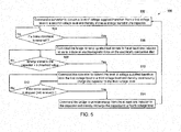
- FIG. 5 a flow chart illustrating a method for improving response time of a braking unit to induce an electromagnetic force, in accordance with aspects of the present disclosure, is depicted.
- the method 500 begins with step 502, where a level of voltage supplied by the power source 118 is converted from a first voltage level to a second voltage level so as to increase energy stored in the capacitor 212.
- the switching unit controller 216 verifies whether a brake command is received from a braking unit controller 114. If the switching unit controller 216 receives the brake command, then the method 500 moves to step 506. At step 506, the switching unit controller 216 commands the bridge 214 to ramp-up electrical current in the at least one inductor 322 so as to induce an electromagnetic force on the electrically conductive disc 106. Particularly, the bridge 214 may provide the energy stored the capacitor 212 to the at least one inductor 322. Since the capacitor 212 is charged to the second voltage level, the electrical current in the at least one inductor 322 may ramp up within a first time period. In one example, the first time period may be in a range from about 5 ms to about 50 ms. It may be noted that the term "ramp up" means ramping up the electrical current up to a significant fraction of its final value.
- step 508 energy stored in the capacitor is verified.
- the switching unit controller 216 may periodically or continually determine whether the energy in the capacitor 212 is below a threshold value. If the energy in the capacitor 212 is below the threshold value, the method moves to step 510.
- the switching unit controller 216 commands the converter 210 to convert the level of voltage supplied therefrom from the first voltage level to a third voltage level so that the capacitor 212 is continuously charged to the third voltage level. This charging is useful because there may be electrical losses in the inductors 322 when the electrical current flows through the inductors 322.
- step 512 When the brake command ceases, that status is detected at step 512, and the method moves to step 514 where the switching unit controller 216 commands the bridge 214 to provide energy from the at least one inductor 322 to the capacitor 212 and thereby recharge the capacitor 212 to a fourth voltage level. Thereafter, the method moves to back to the step 502 where the capacitor may be fully charged in preparation for the next brake command.
- the various embodiments of the system and the method may be used for improving response time of the braking unit aid in riding LVRT within a desired time period. Additionally, when a battery is used as the power source and low cost power electronics are used for the converter and bridge in combination with the capacitor, the cost and size of the system remain reasonable.
Landscapes
- Engineering & Computer Science (AREA)
- Power Engineering (AREA)
- Electric Propulsion And Braking For Vehicles (AREA)
- Stopping Of Electric Motors (AREA)
- Control Of Eletrric Generators (AREA)
Abstract
Description
- The disclosure relates generally to a power generation system and more specifically to improved response time of a braking unit in a power generation system.
- Typically, when a fault in a utility system occurs, voltage in the utility system may suddenly decrease by a certain amount. This sudden decrease of the voltage may result in a sudden reduction of an electrical power output of a generator. As a consequence, there may be unbalance between the electrical power output of the generator and mechanical power input from an engine. This in turn causes acceleration of the generator, which may lead to loss of synchronism between the generator and an electrical grid. Also, stability of the electric grid may be jeopardized if the generator is disconnected. It is therefore desirable for the generators to remain synchronized to the grid, to ride through low voltage conditions, and to be able to feed electric power into the grid immediately after the fault is cleared.
- Various techniques may be employed to overcome the issue of rapid acceleration in the generator during fault conditions. One such technique is to employ a braking unit in a power generation system to control speed of a rotor in the generator. In one example, the braking unit includes one or more coils that are disposed proximate to the rotor, and, when a voltage is applied to these coils, electromagnetic braking force is induced on the rotor such that the speed of the rotor is controlled accordingly. Due to the inductive nature of the coils, the rate of change in the electrical current in the coils is limited by the applied voltage and may require a longer than desired braking response time. To improve the response time, a higher voltage power source may be coupled to the coils. However, such power source would increase the cost and size of the braking unit and may be impractical.
- Hence, there is a need for an improved system and method for providing effective and inexpensive electromagnetic brakes on the rotor. Also, there is a need to provide a braking unit having a fast response time.
- In accordance with one embodiment described herein, a braking system includes a converter, a capacitor coupled to an output of the converter, a bridge coupled in parallel to the capacitor, at least one inductor coupled to the bridge, an electrically conductive disc disposed proximate to the at least one inductor, and a switching unit controller for commanding the converter to convert a level of voltage supplied therefrom from a first voltage level to a second voltage level and thereby increase energy stored in the capacitor, and, upon receiving a brake command, commanding the bridge to ramp-up electrical current in the at least one inductor so as to induce an electromagnetic force on the electrically conductive disc.
- In accordance with a further aspect of the present disclosure, a method includes commanding a converter to increase a level of voltage supplied therefrom from a first voltage level to a second voltage level and thereby increase energy stored in a capacitor coupled in parallel between the converter and a bridge. The method further includes, upon receiving a brake command, causing the bridge to ramp-up electrical current in at least one inductor so as to induce an electromagnetic force on an electrically conductive disc.
- In accordance with another aspect of the present disclosure, a power generation system includes an electrically conductive disc coupled to a rotatable shaft, at least one inductor disposed proximate to the electrically conductive disc, a power source, and a switching unit coupled between the power source and the at least one inductor. The switching unit comprises a converter, a capacitor coupled to an output of the converter, a bridge coupled in parallel to the capacitor, and a switching unit controller for commanding the converter to convert a level of voltage supplied therefrom from a first voltage level to a second voltage level and thereby increase energy stored in the capacitor, and, upon receiving a brake command, commanding the bridge to ramp-up electrical current in the at least one inductor so as to induce an electromagnetic force on the electrically conductive disc.
- These and other features, aspects, and advantages of the present invention will become better understood when the following detailed description is read with reference to the accompanying drawings in which like characters represent like parts throughout the drawings, wherein:
-
FIG. 1 is a diagrammatical representation of a power generation system utilizing a braking unit, in accordance with aspects of the present disclosure. -
FIG. 2 is a block diagram of the braking unit, in accordance with aspects of the present disclosure; -
FIG. 3 is a circuit diagram of the braking unit, in accordance with aspects of the present disclosure; -
FIG. 4 illustrates signal waveforms of voltage and current signals in the braking unit, in accordance with aspects of the present disclosure; and -
FIG. 5 is a flow chart illustrating a method for improving response time of the braking unit to induce an electromagnetic force, in accordance with aspects of the present disclosure. - As will be described in detail hereinafter, various embodiments of exemplary systems and methods for improving a response time of a braking unit in a power generation system are presented. By employing the methods and the various embodiments of the system described hereinafter, speed of a rotatable shaft may be controlled within a desired time period, which in turn improves LVRT (low voltage ride through) or FRT (fault ride through) capabilities in the power generation system.
- Referring to
FIG. 1 , apower generation system 100 having a braking unit, in accordance with aspects of the present disclosure, is depicted. The power generation system is typically used to convert mechanical power into electrical power. For example, in a wind system the kinetic energy of wind passing across a wind turbine is converted into mechanical power. As another example, mechanical power may be generated from a gas engine. This mechanical power is in turn used to generate electrical power. The power generation system includes aprime mover 102, arotatable shaft 104, an electricallyconductive disc 106, agenerator 108, and abraking unit 110. - In one configuration, the
prime mover 102 is mechanically coupled to thepower generator 108 through therotatable shaft 104. Therotatable shaft 104 is typically used to convey mechanical power from theprime mover 102 to thepower generator 108. For example, the mechanical power produced at theprime mover 102 may be used to rotate therotatable shaft 104 at a predetermined speed. This rotation of therotatable shaft 104 in turn rotates a rotor (not shown) of thegenerator 108 to generate electrical power. Further, the generated electrical power at thegenerator 108 may be transferred to apower grid 112. - In the embodiment of
FIG. 1 , the electricallyconductive disc 106 is rigidly coupled to therotatable shaft 104 to control the rotational speed of therotatable shaft 104. Particularly, when a fault (such as a voltage fall or drop) occurs in the system, thebraking unit 110 may receive one or more command signals from thepower generation system 100. In one example, the one or more command signals may include or result from one or more status signals received from thepower generation system 100. The status signals may be representative of a rotational speed of therotatable shaft 104, a voltage in thepower grid 112, a current at thepower generator 108, a mechanical power produced by aprime mover 102, a rotor angle of thepower generator 108, an electrical power produced by thepower generator 108 or combinations thereof. In one embodiment, the rotational speed of therotatable shaft 104 may be determined by aspeed sensor 124 that is operatively coupled to therotatable shaft 104. - In response to receiving the command signals, the
braking unit 110 induces an electromagnetic force on the electricallyconductive disc 106, which in turn regulates or controls the rotational speed of therotatable shaft 104. In one example, the speed of therotatable shaft 104 may be regulated or controlled below a threshold speed value. Moreover, by regulating the rotational speed of therotatable shaft 104, thebraking unit 110 may maintain synchronism between thegenerator 108 and thepower grid 112. - As further shown in
FIG. 1 , thebraking unit 110 includes abraking unit controller 114, aninducting unit 116, apower source 118, and aswitching unit 120. Theinducting unit 116 is coupled to thepower source 118 via theswitching unit 120 and comprises one or more inductors that are disposed proximate to the electricallyconductive disc 106. Further, thebraking unit controller 114 is coupled to theswitching unit 120 and may send abrake command 122 based on one or more command signals received from thepower generation system 100. Thebrake command 122 may be sent to theswitching unit 120 to control the voltage applied to theinducting unit 116. - Referring to
FIG. 2 , a more detailed block diagram of thebraking unit 110, in accordance with aspects of the present disclosure, is depicted showing theswitching unit 120 as comprising aconverter 210, acapacitor 212, abridge 214 and aswitching unit controller 216. - The
power source 118 may comprise a low power source, for example, such as a battery having a voltage at a first voltage level. In one example, the first voltage level may be in a range from about 5V to about 50V. - The
inducting unit 116 is disposed proximate to an electrically conductive disc 106 (FIG. 1 ) that is rigidly coupled to a rotatable shaft 104 (FIG. 1 ) of a power generator 108 (FIG. 1 ). Particularly, the inductingunit 116 comprises one or more inductors that are disposed proximate to the electricallyconductive disc 106 to induce an electromagnetic force on the electricallyconductive disc 106. In one example, the one or more inductors may represent electrical coils that are disposed near either side or both sides of the electricallyconductive disc 106. - The
switching unit 120 is operatively coupled between thepower source 118 and theinducting unit 116 and is used to control the voltage applied to theinducting unit 116 based on abrake command 122 received from thebraking unit controller 114. In the embodiment ofFIG. 2 , theswitching unit 120 comprises theconverter 210, thecapacitor 212, thebridge 214 and theswitching unit controller 216. Although theswitching unit controller 116 is shown as being included within theswitching unit 120 for purposes of example, theswitching unit controller 216 may alternatively be integrated within thebraking unit controller 114 in some embodiments. Theconverter 210 is coupled between thepower source 118 and thecapacitor 212. Theconverter 210 is used to convert the voltage provided by thepower source 118 and thereby increase the energy stored in thecapacitor 212. Further, thebridge 214 is coupled between thecapacitor 212 and the inductingunit 116. Thebridge 214 is used to provide the energy stored in thecapacitor 212 to the one of more inductors when the brake command is received by theswitching unit controller 216. Thebridge 214 may further be used to provide energy from the inductingunit 116 to thecapacitor 212 when the brake command ceases. As used herein "brake command ceases" is intended to cover either (a) the stopping of transmission of the brake command (in the circumstance wherein the switching unit controller continuously receives the command during braking until braking is completed) or (b) a separate command to stop braking (in the circumstance wherein the switching unit controller receives a discrete braking command at one time instance and a separate command to stop braking at a later time instance). Until the brake command ceases, the brake command is referenced as "remaining active." - During operation, the
power source 118 is active, and theconverter 210 converts the voltage provided by thepower source 118 from the first voltage level to the second voltage level which in one example is in the range from about 200V to about 600V for charging thecapacitor 212. In a more specific example, the voltage in thecapacitor 212 is increased to about 400V. - At a later point in time, if the
switching unit controller 216 receives the brake command from thebraking unit controller 114, theswitching unit controller 216 then commands thebridge 214 to provide the voltage in thecapacitor 212 to theinducting unit 116 so as to induce the electromagnetic force on the electrically conductive disc 106 (FIG. 1 ). Particularly, the second voltage in thecapacitor 212 is used to provide a fast ramp-up of electrical current in theinducting unit 116. In one example, the electrical current may be ramped up in theinducting unit 116 within a first time period ranging from about 5 ms to about 50 ms. This fast ramp-up of electrical current in theinducting unit 116 may reduce time to induce the electromagnetic force on the electricallyconductive disc 106, and thus improve the response time of thebraking unit 110 to induce the electromagnetic force on the electricallyconductive disc 106. - When braking, as the electrical current ramps up in the
inducting unit 116, the energy stored in thecapacitor 212 is reduced. In one embodiment, if theswitching unit controller 216 determines that the energy stored in thecapacitor 212 has fallen below a threshold value, theswitching unit controller 216 commands theconverter 210 to again increase the level of voltage supplied by thepower source 118 above the first voltage level. In a more specific embodiment, the increase is not to the level of the second voltage level but is to a third voltage level that is less than the second voltage level. In one example, the third voltage level may be in a range from about 50V to about 100V. In this embodiment, theconverter 210 may continuously charge thecapacitor 212 at the third voltage level while further braking is needed. Thus, thecapacitor 212 may be continuously charged at the third voltage level so that the electrical current may flow continuously in theinducting unit 116 to compensate the electrical losses in the one or more inductors of the inductingunit 116 and maintain the current in one or more inductors at a steady state. - Furthermore, at some point after the speed of the
rotatable shaft 106 is controlled, the brake command will cease. Theswitching unit controller 216 may then command thebridge 214 to stop providing energy from thecapacitor 212 to theinducting unit 116. Further, in an optional embodiment, theswitching unit controller 216 may command theinducting unit 116 to provide any remaining energy to thecapacitor 212 and thereby recharge thecapacitor 212 to a fourth voltage level. Due to electrical losses in the one or more inductors of the inductingunit 116, the fourth voltage level may be less than the second voltage level. In this embodiment, to compensate these electrical losses, theswitching unit controller 216 may then command theconverter 210 to convert the voltage supplied by thepower source 118 from the first voltage level back up to the second voltage level such that thecapacitor 212 is further charged to increase the voltage in thecapacitor 212 from the fourth voltage level to the second voltage level. This cycle may be repeated again if theswitching unit controller 216 once again receives the brake command from thebraking unit controller 114. - Thus, by employing a sufficiently
large capacitor 212 in theswitching unit 120, energy associated with a high enough voltage for fast braking may be stored and may be provided to the inductors to build-up fast ramp-up of electrical current in the one or more inductors of inductingunit 116. This in turn improves the response time of thebraking unit 110 to induce the electromagnetic force on the electricallyconductive disc 106. - Referring to
FIG. 3 a circuit diagram (schematic view) of abraking unit 110, in accordance with aspects of the present disclosure, is depicted. For ease of understanding, thebraking unit 110 is described with reference to the components ofFIGs. 1 and 2 . Thebraking unit 110 includes thebraking unit controller 114, the inductingunit 116, thepower source 118, and theswitching unit 120. - In the embodiment of
FIG. 3 , acapacitor 314 is coupled in parallel to thepower source 118 to filter AC components in the current generated by theconverter 210. Further, in an example embodiment, theconverter 210 includes aninductor 316, aswitch 318, and adiode 319. In one embodiment, theswitch 318 comprises a MOSFET and/or an IGBT, for example. Theswitch 318 is coupled in parallel to thepower source 118 and is controlled to increase a level of voltage provided from thepower source 118 via theinductor 316. For example, theswitching unit controller 216 may toggle theswitch 318 to adjust a duty cycle of the voltage so as to increase the level of voltage provided by thepower source 118. Further, thediode 319 is used to allow the energy associated with the increased level of voltage provided by thepower source 118 towards thecapacitor 212. - The
capacitor 212 is coupled in parallel to theswitch 318 through thediode 319. As discussed with respect toFIG. 2 , thecapacitor 212 is used to store a high voltage before receiving a brake command and to provide the stored high voltage to theinducting unit 116 when the brake command is received. Also, thecapacitor 212 may be partially recharged with the energy in theinducting unit 116 when the brake command ceases. In one embodiment, thecapacitor 212 comprises a capacitor bank for providing enough energy storage. - The
bridge 214 is in turn coupled in parallel to thecapacitor 212 in the embodiment ofFIG. 3 . In one example, thebridge 214 may comprise an H-bridge circuit having two branches coupled in parallel to thecapacitor 212. Each branch comprises a pair ofswitches 320 and a pair ofdiodes 324 coupled to a respective inductor 322 in theinducting unit 116.Switches 320 may comprise MOSFETs in one embodiment. Each pair ofswitches 320 may be turned ON when theswitching unit controller 216 receives the brake command in order to provide the voltage across thecapacitor 212 to the inductors 322 in theinducting unit 116. In one example, theswitches 320 are turned ON to move theswitches 320 from a non-conducting state to a conducting state so that the electrical current flows from the capacitor to the inductors 322 via theswitches 320. - Similarly, each pair of
switches 320 may be turned OFF when the braking ends. Particularly, when the braking ends, theswitches 320 may be turned OFF to move theswitches 320 back to the non-conducting state so that the electrical current does not flow through theswitches 320. However, energy that is accumulated in the inductors 322 may flow in an opposite direction through thediodes 324 to recharge thecapacitor 212 to the fourth voltage level. Moreover, the energy provided by the inductors 322 may not be at the second voltage level due to electrical losses in the inductors 322. Thus, thecapacitor 212 may only be charged to the fourth voltage level which is less than the second voltage level. -
FIG. 4 illustrates example signal waveforms of voltage and current signals in a braking unit, in accordance with aspects of the present disclosure. For ease of understanding, the signal waveforms are described with reference to the components ofFIG. 3 , andFIG. 4 is an example wherein thepower source 118 comprises a battery. The signal waveforms include acapacitor voltage signal 402, a coilcurrent signal 404, and a batterycurrent signal 406. Thecapacitor voltage signal 402 represents voltage across thecapacitor 212, the coilcurrent signal 404 represents electrical current in the inductors 322, and the batterycurrent signal 406 represents electrical current provided by thepower source 118. - As depicted in
FIG. 4 , at time T0, thecapacitor voltage signal 402 is at maximum or peak level (meaning thecapacitor 212 is fully charged to the second voltage level), and the coilcurrent signal 404 and the batterycurrent signal 406 are at zero levels. This is because no current is needed yet by the inducting unit, and, after the capacitor voltage reaches the second voltage level, thepower source 118 need not continue supplying further electrical current until or unless the capacitor later becomes depleted. - Further, at time T1, a brake command is received and the voltage across the
capacitor 212 is provided to the inductors 322. Thus, thecapacitor voltage signal 402 may start to ramp-down and the coilcurrent signal 404 may start to ramp-up. When thecapacitor 212 has very high voltage, such as, for example, about 400V, a change rate of the electrical current in the inductors 322 will also be very high. Therefore, the coilcurrent signal 404 may ramp-up by time T2. The time period between time T1 and T2 is referred to as a first time period. In one example, the first time period may be in a range from about 5 ms to about 50 ms. - Further, after time T2, the coil
current signal 404 may be operable at a steady state. However, electrical losses will be present in the inductors 322 such that some further current will be needed to maintain the coilcurrent signal 404 at the steady state. In the embodiment ofFIG. 4 , after time T2, the batterycurrent signal 406 at a determined level may be continuously provided to thecapacitor 212 so as to maintain the charge of thecapacitor 212 at a third voltage level. In this embodiment, the electrical current from thecapacitor 212 is continuously provided to the inductors 322 to compensate these electrical losses in the inductors 322. - Time T3 represents time at which the brake command ceases. At this time, in the embodiment shown in
FIG. 4 , the energy in the inductors 322 is directed in the opposite direction to recharge the capacitor at the second voltage level. Thus, thecapacitor voltage signal 402 may ramp-up, and the coilcurrent signal 404 may ramp-down by time T4. The time period between time T3 and T4 is referred to as a second time period. In one example, the second time period may be in a range from about 5 ms to about 50 ms. Also, at time T3, thepower source 118 may cease to supply the batterycurrent signal 406 as thecapacitor 212 is recharged by the energy in the inductors 322. Thus, the batterycurrent signal 406 from thepower source 118 may drop to zero level at time T3. This example presumes there is little inductor loss. In practice, the battery current signal may continue for some period of time to make up for any inductor losses and fully ramp back upcapacitor voltage signal 402 as described with respect toFIG. 2 . - Referring to
FIG. 5 , a flow chart illustrating a method for improving response time of a braking unit to induce an electromagnetic force, in accordance with aspects of the present disclosure, is depicted. For ease of understanding, themethod 500 is described with reference to the components ofFIGs. 2 and3 . Themethod 500 begins withstep 502, where a level of voltage supplied by thepower source 118 is converted from a first voltage level to a second voltage level so as to increase energy stored in thecapacitor 212. - Subsequently, at
step 504, theswitching unit controller 216 verifies whether a brake command is received from abraking unit controller 114. If theswitching unit controller 216 receives the brake command, then themethod 500 moves to step 506. Atstep 506, theswitching unit controller 216 commands thebridge 214 to ramp-up electrical current in the at least one inductor 322 so as to induce an electromagnetic force on the electricallyconductive disc 106. Particularly, thebridge 214 may provide the energy stored thecapacitor 212 to the at least one inductor 322. Since thecapacitor 212 is charged to the second voltage level, the electrical current in the at least one inductor 322 may ramp up within a first time period. In one example, the first time period may be in a range from about 5 ms to about 50 ms. It may be noted that the term "ramp up" means ramping up the electrical current up to a significant fraction of its final value. - At
step 508, energy stored in the capacitor is verified. Particularly, theswitching unit controller 216 may periodically or continually determine whether the energy in thecapacitor 212 is below a threshold value. If the energy in thecapacitor 212 is below the threshold value, the method moves to step 510. - At
step 510, theswitching unit controller 216 commands theconverter 210 to convert the level of voltage supplied therefrom from the first voltage level to a third voltage level so that thecapacitor 212 is continuously charged to the third voltage level. This charging is useful because there may be electrical losses in the inductors 322 when the electrical current flows through the inductors 322. - When the brake command ceases, that status is detected at
step 512, and the method moves to step 514 where theswitching unit controller 216 commands thebridge 214 to provide energy from the at least one inductor 322 to thecapacitor 212 and thereby recharge thecapacitor 212 to a fourth voltage level. Thereafter, the method moves to back to thestep 502 where the capacitor may be fully charged in preparation for the next brake command. - The various embodiments of the system and the method may be used for improving response time of the braking unit aid in riding LVRT within a desired time period. Additionally, when a battery is used as the power source and low cost power electronics are used for the converter and bridge in combination with the capacitor, the cost and size of the system remain reasonable.
- While only certain features of the invention have been illustrated and described herein, many modifications and changes will occur to those skilled in the art. It is, therefore, to be understood that the appended claims are intended to cover all such modifications and changes as fall within the true spirit of the invention.
Claims (15)
- A braking system (110), comprising:a converter (210);a capacitor (212) coupled to an output of the converter (210);a bridge (214) coupled in parallel to the capacitor (212);at least one inductor coupled (116) to the bridge (214);an electrically conductive disc (106) disposed proximate to the at least one inductor (116); anda switching unit controller (216) for commanding the converter (210) to convert a level of voltage supplied therefrom from a first voltage level to a second voltage level and thereby increase energy stored in the capacitor (212), and, upon receiving a brake command, commanding the bridge (214) to ramp-up electrical current in the at least one inductor (116) so as to induce an electromagnetic force on the electrically conductive disc (106).
- The braking system of claim 1, wherein the electrical current is ramped up in the at least one inductor (116) within 50 ms.
- The braking system of claim 1 or 2, wherein the switching unit controller (216) is programmed for, after commanding the bridge (214) to ramp-up electrical current in the at least one inductor (116) and upon determining that the energy stored in the capacitor (212) is below a threshold value, commanding the converter (210) to increase the level of voltage supplied therefrom from the first voltage level to a third voltage level.
- The braking system of claim 3, wherein the third voltage level is less than the second voltage level.
- The braking system of claim 3 or 4, wherein the switching unit controller (216) is programmed for continuing to command the converter (210) to increase the level of voltage supplied therefrom from the first voltage level to the third voltage level until the brake command ceases.
- The braking system of any preceding claim, wherein the switching unit controller (216) is further configured for commanding the bridge (214) to provide energy from the at least one inductor (116) to the capacitor (212) and thereby recharge the capacitor (212) to a fourth voltage level when the brake command ceases.
- The braking system of claim 6, wherein the electrical current in the at least one inductor (116) is ramped down within 50 ms after initiation of recharging of the capacitor (212).
- The braking system of claim 7, wherein the switching unit controller (216) is further configured for, after the capacitor (212) is recharged to the fourth voltage level, commanding the converter (210) to convert the level of voltage supplied therefrom from the first voltage level to the second voltage level.
- The braking system of any preceding claim, wherein the first voltage level ranges from about 5V to about 50V.
- The braking system of claim 9, wherein the second voltage level ranges from about 200V to about 600V.
- A method comprising:commanding a converter (210) to increase a level of voltage supplied therefrom from a first voltage level to a second voltage level and thereby increase energy stored in a capacitor (212) coupled in parallel between the converter (210) and a bridge (214); andupon receiving a brake command, causing the bridge (214) to ramp-up electrical current in at least one inductor (116) so as to induce an electromagnetic force on an electrically conductive disc (106).
- The method of claim 11, further comprising, while the brake command remains active:upon determining that the energy stored in the capacitor (212) is below a threshold value,commanding the converter (210) to convert the level of voltage supplied therefrom from the first voltage level to a third voltage level until the brake command ceases.
- The method of claim 12, further comprising, upon the brake command ceasing:commanding the bridge (214) to provide energy from the at least one inductor (116) to the capacitor (212) and thereby recharge the capacitor (212) to a fourth voltage level.
- The method of claim 13, further comprising, after the capacitor (212) is recharged to the fourth voltage level, commanding the converter (210) to convert the level of voltage supplied therefrom from the first voltage level to the second voltage level and thereby increase the energy stored in the capacitor (212).
- A power generation system comprising a power source and the braking system of any of claims 1 to 10.
Applications Claiming Priority (1)
| Application Number | Priority Date | Filing Date | Title |
|---|---|---|---|
| US14/339,552 US9407187B2 (en) | 2012-06-28 | 2014-07-24 | System and method for improving response time of a braking unit |
Publications (2)
| Publication Number | Publication Date |
|---|---|
| EP2988412A1 true EP2988412A1 (en) | 2016-02-24 |
| EP2988412B1 EP2988412B1 (en) | 2019-09-18 |
Family
ID=54106099
Family Applications (1)
| Application Number | Title | Priority Date | Filing Date |
|---|---|---|---|
| EP15177889.1A Active EP2988412B1 (en) | 2014-07-24 | 2015-07-22 | System and method for improving response time of a braking unit |
Country Status (3)
| Country | Link |
|---|---|
| EP (1) | EP2988412B1 (en) |
| JP (1) | JP2016025848A (en) |
| CN (1) | CN105305900B (en) |
Families Citing this family (1)
| Publication number | Priority date | Publication date | Assignee | Title |
|---|---|---|---|---|
| CN105552955B (en) * | 2015-12-18 | 2018-03-13 | 南京南瑞继保电气有限公司 | The control system and method that photovoltaic combining inverter low-voltage and no-voltage are passed through |
Citations (3)
| Publication number | Priority date | Publication date | Assignee | Title |
|---|---|---|---|---|
| JPS60167602A (en) * | 1984-02-06 | 1985-08-31 | Hitachi Ltd | Eddy current controller of electric railcar |
| EP2680433A2 (en) * | 2012-06-28 | 2014-01-01 | General Electric Company | Electromagnetic braking systems and methods |
| WO2014013606A1 (en) * | 2012-07-20 | 2014-01-23 | トヨタ自動車株式会社 | Fuel cell system |
Family Cites Families (5)
| Publication number | Priority date | Publication date | Assignee | Title |
|---|---|---|---|---|
| JPS5615631U (en) * | 1979-07-12 | 1981-02-10 | ||
| JPH06327299A (en) * | 1993-05-14 | 1994-11-25 | Sawafuji Electric Co Ltd | Exciting current driving equipment for exciting coil type retarder |
| JPH06335300A (en) * | 1993-05-21 | 1994-12-02 | Sawafuji Electric Co Ltd | Power supply for electromagnetic retarder |
| JPH07267087A (en) * | 1994-03-30 | 1995-10-17 | East Japan Railway Co | Rail brake power supply |
| EP2727230A2 (en) * | 2011-07-01 | 2014-05-07 | Linak A/S | Power supply with output rectifier |
-
2015
- 2015-07-22 JP JP2015144650A patent/JP2016025848A/en active Pending
- 2015-07-22 EP EP15177889.1A patent/EP2988412B1/en active Active
- 2015-07-24 CN CN201510440604.2A patent/CN105305900B/en not_active Expired - Fee Related
Patent Citations (4)
| Publication number | Priority date | Publication date | Assignee | Title |
|---|---|---|---|---|
| JPS60167602A (en) * | 1984-02-06 | 1985-08-31 | Hitachi Ltd | Eddy current controller of electric railcar |
| EP2680433A2 (en) * | 2012-06-28 | 2014-01-01 | General Electric Company | Electromagnetic braking systems and methods |
| WO2014013606A1 (en) * | 2012-07-20 | 2014-01-23 | トヨタ自動車株式会社 | Fuel cell system |
| US20150217660A1 (en) * | 2012-07-20 | 2015-08-06 | Toyota Jidosha Kabushiki Kaisha | Fuel cell system |
Also Published As
| Publication number | Publication date |
|---|---|
| CN105305900B (en) | 2019-10-18 |
| JP2016025848A (en) | 2016-02-08 |
| CN105305900A (en) | 2016-02-03 |
| EP2988412B1 (en) | 2019-09-18 |
Similar Documents
| Publication | Publication Date | Title |
|---|---|---|
| US9407187B2 (en) | System and method for improving response time of a braking unit | |
| CN102398526B (en) | There is the ground handling trolley of the running driving device of electricity | |
| CN105034837B (en) | Electric vehicle | |
| KR102050174B1 (en) | How to adjust wind turbine power draw | |
| US8853875B2 (en) | Wind power generation system and method for controlling excitation synchronous generator thereof | |
| JP2015140052A (en) | Hybrid vehicle | |
| CN110671265A (en) | Anti-resonance control method and device for wind driven generator | |
| US20170359010A1 (en) | Switched reluctance generator based automotive power generating system | |
| EP2527606A2 (en) | Closed energy combined cycle system and operation method thereof | |
| CN103036448A (en) | Active switching frequency modulation | |
| EP2988412B1 (en) | System and method for improving response time of a braking unit | |
| US20180226907A1 (en) | Method and system for adjusting wind turbine power take-off | |
| KR20120100228A (en) | Double-sided converter for initial operating in wind turbine, apparatus and method for initial operating using the same | |
| KR101506206B1 (en) | System for controlling self excitation capacitance of single phase induction generator | |
| JP4950162B2 (en) | Vehicle power supply | |
| US9379575B2 (en) | Battery charger noise reduction by frequency switching | |
| US8198871B2 (en) | Time lag reduction circuit for alternating current generator and electric drive machine using same | |
| JP6470947B2 (en) | Drive system and diesel car | |
| EP3340456A1 (en) | An electric system for an electromechanical power transmission chain | |
| JP2017118764A (en) | Output control device for wind power generation | |
| EP2924866B1 (en) | An electrical power converter for a working machine | |
| KR101674422B1 (en) | Bidirectional current-controlable electromagnetic regenerative retarder |
Legal Events
| Date | Code | Title | Description |
|---|---|---|---|
| PUAI | Public reference made under article 153(3) epc to a published international application that has entered the european phase |
Free format text: ORIGINAL CODE: 0009012 |
|
| AK | Designated contracting states |
Kind code of ref document: A1 Designated state(s): AL AT BE BG CH CY CZ DE DK EE ES FI FR GB GR HR HU IE IS IT LI LT LU LV MC MK MT NL NO PL PT RO RS SE SI SK SM TR |
|
| AX | Request for extension of the european patent |
Extension state: BA ME |
|
| 17P | Request for examination filed |
Effective date: 20160824 |
|
| RBV | Designated contracting states (corrected) |
Designated state(s): AL AT BE BG CH CY CZ DE DK EE ES FI FR GB GR HR HU IE IS IT LI LT LU LV MC MK MT NL NO PL PT RO RS SE SI SK SM TR |
|
| GRAP | Despatch of communication of intention to grant a patent |
Free format text: ORIGINAL CODE: EPIDOSNIGR1 |
|
| STAA | Information on the status of an ep patent application or granted ep patent |
Free format text: STATUS: GRANT OF PATENT IS INTENDED |
|
| RIC1 | Information provided on ipc code assigned before grant |
Ipc: H02P 9/02 20060101AFI20190312BHEP Ipc: H02P 3/04 20060101ALI20190312BHEP |
|
| RIN1 | Information on inventor provided before grant (corrected) |
Inventor name: LIEBSCHER, UWE Inventor name: BOELD, CHRISTOPHER Inventor name: PANOSYAN, ARA Inventor name: SCHROEDER, STAFAN Inventor name: DONG, XIAOTING Inventor name: SCHAUMBERGER, HERBERT |
|
| INTG | Intention to grant announced |
Effective date: 20190411 |
|
| RAP1 | Party data changed (applicant data changed or rights of an application transferred) |
Owner name: AI ALPINE US BIDCO INC. |
|
| GRAS | Grant fee paid |
Free format text: ORIGINAL CODE: EPIDOSNIGR3 |
|
| GRAA | (expected) grant |
Free format text: ORIGINAL CODE: 0009210 |
|
| STAA | Information on the status of an ep patent application or granted ep patent |
Free format text: STATUS: THE PATENT HAS BEEN GRANTED |
|
| AK | Designated contracting states |
Kind code of ref document: B1 Designated state(s): AL AT BE BG CH CY CZ DE DK EE ES FI FR GB GR HR HU IE IS IT LI LT LU LV MC MK MT NL NO PL PT RO RS SE SI SK SM TR |
|
| REG | Reference to a national code |
Ref country code: GB Ref legal event code: FG4D |
|
| REG | Reference to a national code |
Ref country code: CH Ref legal event code: EP |
|
| REG | Reference to a national code |
Ref country code: DE Ref legal event code: R096 Ref document number: 602015038125 Country of ref document: DE |
|
| REG | Reference to a national code |
Ref country code: AT Ref legal event code: REF Ref document number: 1182500 Country of ref document: AT Kind code of ref document: T Effective date: 20191015 |
|
| REG | Reference to a national code |
Ref country code: IE Ref legal event code: FG4D |
|
| REG | Reference to a national code |
Ref country code: NL Ref legal event code: MP Effective date: 20190918 |
|
| PG25 | Lapsed in a contracting state [announced via postgrant information from national office to epo] |
Ref country code: FI Free format text: LAPSE BECAUSE OF FAILURE TO SUBMIT A TRANSLATION OF THE DESCRIPTION OR TO PAY THE FEE WITHIN THE PRESCRIBED TIME-LIMIT Effective date: 20190918 Ref country code: NO Free format text: LAPSE BECAUSE OF FAILURE TO SUBMIT A TRANSLATION OF THE DESCRIPTION OR TO PAY THE FEE WITHIN THE PRESCRIBED TIME-LIMIT Effective date: 20191218 Ref country code: SE Free format text: LAPSE BECAUSE OF FAILURE TO SUBMIT A TRANSLATION OF THE DESCRIPTION OR TO PAY THE FEE WITHIN THE PRESCRIBED TIME-LIMIT Effective date: 20190918 Ref country code: HR Free format text: LAPSE BECAUSE OF FAILURE TO SUBMIT A TRANSLATION OF THE DESCRIPTION OR TO PAY THE FEE WITHIN THE PRESCRIBED TIME-LIMIT Effective date: 20190918 Ref country code: BG Free format text: LAPSE BECAUSE OF FAILURE TO SUBMIT A TRANSLATION OF THE DESCRIPTION OR TO PAY THE FEE WITHIN THE PRESCRIBED TIME-LIMIT Effective date: 20191218 Ref country code: LT Free format text: LAPSE BECAUSE OF FAILURE TO SUBMIT A TRANSLATION OF THE DESCRIPTION OR TO PAY THE FEE WITHIN THE PRESCRIBED TIME-LIMIT Effective date: 20190918 |
|
| REG | Reference to a national code |
Ref country code: LT Ref legal event code: MG4D |
|
| PG25 | Lapsed in a contracting state [announced via postgrant information from national office to epo] |
Ref country code: RS Free format text: LAPSE BECAUSE OF FAILURE TO SUBMIT A TRANSLATION OF THE DESCRIPTION OR TO PAY THE FEE WITHIN THE PRESCRIBED TIME-LIMIT Effective date: 20190918 Ref country code: LV Free format text: LAPSE BECAUSE OF FAILURE TO SUBMIT A TRANSLATION OF THE DESCRIPTION OR TO PAY THE FEE WITHIN THE PRESCRIBED TIME-LIMIT Effective date: 20190918 Ref country code: AL Free format text: LAPSE BECAUSE OF FAILURE TO SUBMIT A TRANSLATION OF THE DESCRIPTION OR TO PAY THE FEE WITHIN THE PRESCRIBED TIME-LIMIT Effective date: 20190918 Ref country code: GR Free format text: LAPSE BECAUSE OF FAILURE TO SUBMIT A TRANSLATION OF THE DESCRIPTION OR TO PAY THE FEE WITHIN THE PRESCRIBED TIME-LIMIT Effective date: 20191219 |
|
| REG | Reference to a national code |
Ref country code: AT Ref legal event code: MK05 Ref document number: 1182500 Country of ref document: AT Kind code of ref document: T Effective date: 20190918 |
|
| PG25 | Lapsed in a contracting state [announced via postgrant information from national office to epo] |
Ref country code: PL Free format text: LAPSE BECAUSE OF FAILURE TO SUBMIT A TRANSLATION OF THE DESCRIPTION OR TO PAY THE FEE WITHIN THE PRESCRIBED TIME-LIMIT Effective date: 20190918 Ref country code: NL Free format text: LAPSE BECAUSE OF FAILURE TO SUBMIT A TRANSLATION OF THE DESCRIPTION OR TO PAY THE FEE WITHIN THE PRESCRIBED TIME-LIMIT Effective date: 20190918 Ref country code: PT Free format text: LAPSE BECAUSE OF FAILURE TO SUBMIT A TRANSLATION OF THE DESCRIPTION OR TO PAY THE FEE WITHIN THE PRESCRIBED TIME-LIMIT Effective date: 20200120 Ref country code: ES Free format text: LAPSE BECAUSE OF FAILURE TO SUBMIT A TRANSLATION OF THE DESCRIPTION OR TO PAY THE FEE WITHIN THE PRESCRIBED TIME-LIMIT Effective date: 20190918 Ref country code: RO Free format text: LAPSE BECAUSE OF FAILURE TO SUBMIT A TRANSLATION OF THE DESCRIPTION OR TO PAY THE FEE WITHIN THE PRESCRIBED TIME-LIMIT Effective date: 20190918 Ref country code: IT Free format text: LAPSE BECAUSE OF FAILURE TO SUBMIT A TRANSLATION OF THE DESCRIPTION OR TO PAY THE FEE WITHIN THE PRESCRIBED TIME-LIMIT Effective date: 20190918 Ref country code: AT Free format text: LAPSE BECAUSE OF FAILURE TO SUBMIT A TRANSLATION OF THE DESCRIPTION OR TO PAY THE FEE WITHIN THE PRESCRIBED TIME-LIMIT Effective date: 20190918 Ref country code: EE Free format text: LAPSE BECAUSE OF FAILURE TO SUBMIT A TRANSLATION OF THE DESCRIPTION OR TO PAY THE FEE WITHIN THE PRESCRIBED TIME-LIMIT Effective date: 20190918 |
|
| PG25 | Lapsed in a contracting state [announced via postgrant information from national office to epo] |
Ref country code: SM Free format text: LAPSE BECAUSE OF FAILURE TO SUBMIT A TRANSLATION OF THE DESCRIPTION OR TO PAY THE FEE WITHIN THE PRESCRIBED TIME-LIMIT Effective date: 20190918 Ref country code: CZ Free format text: LAPSE BECAUSE OF FAILURE TO SUBMIT A TRANSLATION OF THE DESCRIPTION OR TO PAY THE FEE WITHIN THE PRESCRIBED TIME-LIMIT Effective date: 20190918 Ref country code: IS Free format text: LAPSE BECAUSE OF FAILURE TO SUBMIT A TRANSLATION OF THE DESCRIPTION OR TO PAY THE FEE WITHIN THE PRESCRIBED TIME-LIMIT Effective date: 20200224 Ref country code: SK Free format text: LAPSE BECAUSE OF FAILURE TO SUBMIT A TRANSLATION OF THE DESCRIPTION OR TO PAY THE FEE WITHIN THE PRESCRIBED TIME-LIMIT Effective date: 20190918 |
|
| REG | Reference to a national code |
Ref country code: DE Ref legal event code: R097 Ref document number: 602015038125 Country of ref document: DE |
|
| PLBE | No opposition filed within time limit |
Free format text: ORIGINAL CODE: 0009261 |
|
| STAA | Information on the status of an ep patent application or granted ep patent |
Free format text: STATUS: NO OPPOSITION FILED WITHIN TIME LIMIT |
|
| PG2D | Information on lapse in contracting state deleted |
Ref country code: IS |
|
| PG25 | Lapsed in a contracting state [announced via postgrant information from national office to epo] |
Ref country code: DK Free format text: LAPSE BECAUSE OF FAILURE TO SUBMIT A TRANSLATION OF THE DESCRIPTION OR TO PAY THE FEE WITHIN THE PRESCRIBED TIME-LIMIT Effective date: 20190918 Ref country code: IS Free format text: LAPSE BECAUSE OF FAILURE TO SUBMIT A TRANSLATION OF THE DESCRIPTION OR TO PAY THE FEE WITHIN THE PRESCRIBED TIME-LIMIT Effective date: 20200119 |
|
| PGFP | Annual fee paid to national office [announced via postgrant information from national office to epo] |
Ref country code: FR Payment date: 20200623 Year of fee payment: 6 |
|
| 26N | No opposition filed |
Effective date: 20200619 |
|
| PG25 | Lapsed in a contracting state [announced via postgrant information from national office to epo] |
Ref country code: SI Free format text: LAPSE BECAUSE OF FAILURE TO SUBMIT A TRANSLATION OF THE DESCRIPTION OR TO PAY THE FEE WITHIN THE PRESCRIBED TIME-LIMIT Effective date: 20190918 |
|
| PGFP | Annual fee paid to national office [announced via postgrant information from national office to epo] |
Ref country code: DE Payment date: 20200622 Year of fee payment: 6 |
|
| PG25 | Lapsed in a contracting state [announced via postgrant information from national office to epo] |
Ref country code: MC Free format text: LAPSE BECAUSE OF FAILURE TO SUBMIT A TRANSLATION OF THE DESCRIPTION OR TO PAY THE FEE WITHIN THE PRESCRIBED TIME-LIMIT Effective date: 20190918 |
|
| REG | Reference to a national code |
Ref country code: CH Ref legal event code: PL |
|
| GBPC | Gb: european patent ceased through non-payment of renewal fee |
Effective date: 20200722 |
|
| REG | Reference to a national code |
Ref country code: BE Ref legal event code: MM Effective date: 20200731 |
|
| PG25 | Lapsed in a contracting state [announced via postgrant information from national office to epo] |
Ref country code: CH Free format text: LAPSE BECAUSE OF NON-PAYMENT OF DUE FEES Effective date: 20200731 Ref country code: GB Free format text: LAPSE BECAUSE OF NON-PAYMENT OF DUE FEES Effective date: 20200722 Ref country code: LU Free format text: LAPSE BECAUSE OF NON-PAYMENT OF DUE FEES Effective date: 20200722 Ref country code: LI Free format text: LAPSE BECAUSE OF NON-PAYMENT OF DUE FEES Effective date: 20200731 |
|
| PG25 | Lapsed in a contracting state [announced via postgrant information from national office to epo] |
Ref country code: BE Free format text: LAPSE BECAUSE OF NON-PAYMENT OF DUE FEES Effective date: 20200731 |
|
| PG25 | Lapsed in a contracting state [announced via postgrant information from national office to epo] |
Ref country code: IE Free format text: LAPSE BECAUSE OF NON-PAYMENT OF DUE FEES Effective date: 20200722 |
|
| REG | Reference to a national code |
Ref country code: DE Ref legal event code: R119 Ref document number: 602015038125 Country of ref document: DE |
|
| PG25 | Lapsed in a contracting state [announced via postgrant information from national office to epo] |
Ref country code: DE Free format text: LAPSE BECAUSE OF NON-PAYMENT OF DUE FEES Effective date: 20220201 |
|
| PG25 | Lapsed in a contracting state [announced via postgrant information from national office to epo] |
Ref country code: TR Free format text: LAPSE BECAUSE OF FAILURE TO SUBMIT A TRANSLATION OF THE DESCRIPTION OR TO PAY THE FEE WITHIN THE PRESCRIBED TIME-LIMIT Effective date: 20190918 Ref country code: MT Free format text: LAPSE BECAUSE OF FAILURE TO SUBMIT A TRANSLATION OF THE DESCRIPTION OR TO PAY THE FEE WITHIN THE PRESCRIBED TIME-LIMIT Effective date: 20190918 Ref country code: FR Free format text: LAPSE BECAUSE OF NON-PAYMENT OF DUE FEES Effective date: 20210731 Ref country code: CY Free format text: LAPSE BECAUSE OF FAILURE TO SUBMIT A TRANSLATION OF THE DESCRIPTION OR TO PAY THE FEE WITHIN THE PRESCRIBED TIME-LIMIT Effective date: 20190918 |
|
| PG25 | Lapsed in a contracting state [announced via postgrant information from national office to epo] |
Ref country code: MK Free format text: LAPSE BECAUSE OF FAILURE TO SUBMIT A TRANSLATION OF THE DESCRIPTION OR TO PAY THE FEE WITHIN THE PRESCRIBED TIME-LIMIT Effective date: 20190918 |