EP2988311A1 - Pressure compensated subsea electrical system - Google Patents
Pressure compensated subsea electrical system Download PDFInfo
- Publication number
- EP2988311A1 EP2988311A1 EP14181874.0A EP14181874A EP2988311A1 EP 2988311 A1 EP2988311 A1 EP 2988311A1 EP 14181874 A EP14181874 A EP 14181874A EP 2988311 A1 EP2988311 A1 EP 2988311A1
- Authority
- EP
- European Patent Office
- Prior art keywords
- electrical system
- pressure
- transformer
- subsea electrical
- power converter
- Prior art date
- Legal status (The legal status is an assumption and is not a legal conclusion. Google has not performed a legal analysis and makes no representation as to the accuracy of the status listed.)
- Granted
Links
Images



Classifications
-
- H—ELECTRICITY
- H05—ELECTRIC TECHNIQUES NOT OTHERWISE PROVIDED FOR
- H05K—PRINTED CIRCUITS; CASINGS OR CONSTRUCTIONAL DETAILS OF ELECTRIC APPARATUS; MANUFACTURE OF ASSEMBLAGES OF ELECTRICAL COMPONENTS
- H05K5/00—Casings, cabinets or drawers for electric apparatus
- H05K5/06—Hermetically-sealed casings
- H05K5/068—Hermetically-sealed casings having a pressure compensation device, e.g. membrane
-
- F—MECHANICAL ENGINEERING; LIGHTING; HEATING; WEAPONS; BLASTING
- F28—HEAT EXCHANGE IN GENERAL
- F28D—HEAT-EXCHANGE APPARATUS, NOT PROVIDED FOR IN ANOTHER SUBCLASS, IN WHICH THE HEAT-EXCHANGE MEDIA DO NOT COME INTO DIRECT CONTACT
- F28D1/00—Heat-exchange apparatus having stationary conduit assemblies for one heat-exchange medium only, the media being in contact with different sides of the conduit wall, in which the other heat-exchange medium is a large body of fluid, e.g. domestic or motor car radiators
- F28D1/02—Heat-exchange apparatus having stationary conduit assemblies for one heat-exchange medium only, the media being in contact with different sides of the conduit wall, in which the other heat-exchange medium is a large body of fluid, e.g. domestic or motor car radiators with heat-exchange conduits immersed in the body of fluid
- F28D1/0206—Heat exchangers immersed in a large body of liquid
- F28D1/022—Heat exchangers immersed in a large body of liquid for immersion in a natural body of water, e.g. marine radiators
-
- H—ELECTRICITY
- H01—ELECTRIC ELEMENTS
- H01F—MAGNETS; INDUCTANCES; TRANSFORMERS; SELECTION OF MATERIALS FOR THEIR MAGNETIC PROPERTIES
- H01F27/00—Details of transformers or inductances, in general
- H01F27/08—Cooling; Ventilating
- H01F27/10—Liquid cooling
- H01F27/12—Oil cooling
- H01F27/14—Expansion chambers; Oil conservators; Gas cushions; Arrangements for purifying, drying, or filling
-
- H—ELECTRICITY
- H02—GENERATION; CONVERSION OR DISTRIBUTION OF ELECTRIC POWER
- H02M—APPARATUS FOR CONVERSION BETWEEN AC AND AC, BETWEEN AC AND DC, OR BETWEEN DC AND DC, AND FOR USE WITH MAINS OR SIMILAR POWER SUPPLY SYSTEMS; CONVERSION OF DC OR AC INPUT POWER INTO SURGE OUTPUT POWER; CONTROL OR REGULATION THEREOF
- H02M7/00—Conversion of AC power input into DC power output; Conversion of DC power input into AC power output
- H02M7/02—Conversion of AC power input into DC power output without possibility of reversal
- H02M7/04—Conversion of AC power input into DC power output without possibility of reversal by static converters
- H02M7/06—Conversion of AC power input into DC power output without possibility of reversal by static converters using discharge tubes without control electrode or semiconductor devices without control electrode
- H02M7/068—Conversion of AC power input into DC power output without possibility of reversal by static converters using discharge tubes without control electrode or semiconductor devices without control electrode mounted on a transformer
-
- H—ELECTRICITY
- H05—ELECTRIC TECHNIQUES NOT OTHERWISE PROVIDED FOR
- H05K—PRINTED CIRCUITS; CASINGS OR CONSTRUCTIONAL DETAILS OF ELECTRIC APPARATUS; MANUFACTURE OF ASSEMBLAGES OF ELECTRICAL COMPONENTS
- H05K7/00—Constructional details common to different types of electric apparatus
- H05K7/20—Modifications to facilitate cooling, ventilating, or heating
- H05K7/20218—Modifications to facilitate cooling, ventilating, or heating using a liquid coolant without phase change in electronic enclosures
- H05K7/20236—Modifications to facilitate cooling, ventilating, or heating using a liquid coolant without phase change in electronic enclosures by immersion
-
- H—ELECTRICITY
- H05—ELECTRIC TECHNIQUES NOT OTHERWISE PROVIDED FOR
- H05K—PRINTED CIRCUITS; CASINGS OR CONSTRUCTIONAL DETAILS OF ELECTRIC APPARATUS; MANUFACTURE OF ASSEMBLAGES OF ELECTRICAL COMPONENTS
- H05K7/00—Constructional details common to different types of electric apparatus
- H05K7/20—Modifications to facilitate cooling, ventilating, or heating
- H05K7/2089—Modifications to facilitate cooling, ventilating, or heating for power electronics, e.g. for inverters for controlling motor
- H05K7/209—Heat transfer by conduction from internal heat source to heat radiating structure
-
- H—ELECTRICITY
- H05—ELECTRIC TECHNIQUES NOT OTHERWISE PROVIDED FOR
- H05K—PRINTED CIRCUITS; CASINGS OR CONSTRUCTIONAL DETAILS OF ELECTRIC APPARATUS; MANUFACTURE OF ASSEMBLAGES OF ELECTRICAL COMPONENTS
- H05K7/00—Constructional details common to different types of electric apparatus
- H05K7/20—Modifications to facilitate cooling, ventilating, or heating
- H05K7/2089—Modifications to facilitate cooling, ventilating, or heating for power electronics, e.g. for inverters for controlling motor
- H05K7/20927—Liquid coolant without phase change
Definitions
- the invention relates to subsea electrical systems, and particularly to a pressure compensated subsea electrical system.
- electric subsea installations and devices usually demand high standards regarding durability, long-term functionality and independence during operation.
- Electric subsea installations that need to be cooled during operation such as subsea converters, require an autonomous and durable cooling of its components.
- a dielectric liquid of low compressibility such as for example mineral oil as a cooling fluid.
- the dielectric fluid could also be composed of natural or synthetic esters.
- the dielectric fluid is used to provide a pressure compensated environment, and additionally functions as an electric insulation medium of electric components, such as capacitor units, placed in the electric installation.
- the tanks of power-electronic subsea equipment, such as subsea converters are thus typically filled with oil, which acts as a combined electric insulation and cooling medium. The oil receives heat from the internal converter components and transfers it to the sea-water through the tank wall or through a heat exchanger.
- the tank is provided with a pressure compensation system, so that the internal pressure is close or equal to the external pressure.
- Arrangements comprising such pressure compensation systems will henceforth be called pressure compensated arrangements.
- the provision of a pressure compensation system imposes significantly less stress on the tank walls in comparison to tanks (such as being part of a subsea electrical system) without pressure compensation systems.
- the pressure at 3000 meters depth is 300 bar.
- a power converter requires several electrical connections to a transformer.
- Known subsea power systems typically position the power converter and the transformer in separate tanks with separate pressure compensation systems, and with wet connections for the electrical coupling.
- FIG. 1 schematically illustrates such a known pressure compensated subsea electrical system 1a.
- the pressure compensated subsea electrical system 1a comprises a first tank comprising a transformer 3 and a second tank comprising a power converter 4.
- the tanks are joined by a connection.
- Each tank is filled with a dielectric fluid 12 and has its own separate pressure compensation system 2a, 2b.
- WO 2008/055515 (see, especially Figure 3 therein) describes a converter and a transformer, both located within one liquid-tight housing. According to WO 2008/055515 the converter is located within a further liquid-tight housing and there is consequently no fluid communication between them.
- EP2579438 discloses a converter and a transformer but does not mention fluid communication.
- FIG. 1b schematically illustrates such a known pressure compensated subsea electrical system 1b.
- the subsea electrical system 1b thus comprises a first tank, filled with a dielectric fluid 12, comprising a transformer 3 and having a pressure compensation system 2a.
- the first tank in turn further comprises a second tank.
- the second tank also filled with a dielectric fluid 12, comprises a power converter 4 and has a pressure compensation system 2b.
- the power converter has high thermal losses but requires low temperatures in order to operate efficiently.
- the tank wall surface is in general not sufficient to achieve the required cooling.
- the surface can be extended by using tank corrugations, cooling fins, or an external heat exchanger, but this increases the cost and weight of the pressure compensated subsea electrical system.
- the transformer is less sensitive to high temperatures.
- An object of embodiments herein is to provide efficient pressure compensated subsea electrical systems comprising a transformer and a power converter.
- a pressure compensated subsea electrical system comprises a housing filled with a dielectric liquid.
- the housing has a first housing portion and a second housing portion in pressure communication with each other.
- the first housing portion comprises a transformer, and the second housing portion comprises a power converter.
- the pressure compensated subsea electrical system comprises a pressure compensator arranged to compensate pressure inside the housing.
- the pressure compensator is enabled to compensate pressure in both the first housing portion and the second housing portion.
- the housing will have a large surface that can be used to reduce the power converter operating temperature.
- the housing can be extended vertically to improve natural convective flow of the dielectric liquid.
- this allows for temperature sensitive components to be placed in cold environment.
- the subsea transformer can be positioned such that transformer losses generate a natural convective flow of the dielectric liquid that helps to cool the subsea power converter. This can be achieved either by positioning the transformer above the power converter or by providing cooling channels through a dividing wall.
- Cooling systems for electric equipment are used to cool down electric components, such as transformers, power converters, power electronic building blocks, semiconductor modules, connectors, and capacitor units. Such electric components generate heat that needs to be dissipated by the cooling system.
- the cooling systems of subsea electrical systems are usually designed in a simple manner avoiding any unnecessary parts and mechanisms. Generally it is desirable to have passive cooling systems, thus cooling systems without any driven or powered parts, such as for example without pumps, to cool down the electric equipment.
- natural convection is used. Cooling by natural convection uses the heat transfer from the cooling liquid to the surrounding sea water to generate circulation within the cooling system and thus within the electrical systems.
- Figures 3 , 4 , 6 , 8 , and 9 are cross-sectional side views illustrating pressure compensated subsea electrical systems according to embodiments.
- Figures 5 and 7 schematically illustrate arrangements of a transformer and power converter components for use in a pressure compensated subsea electrical system according to embodiments.
- a pressure compensated subsea electrical system 5a, 5b, 5c, 5d, 5e In general terms, there is provided a pressure compensated subsea electrical system 5a, 5b, 5c, 5d, 5e.
- the pressure compensated subsea electrical system 5a, 5b, 5c, 5d, 5e comprises a housing 8.
- the housing 8 may be a tank.
- the housing 8 is filled with a dielectric liquid 12.
- the dielectric liquid 12 may be oil.
- the housing 8 has a first housing portion 8a and a second housing portion 8b.
- the first housing portion 8a and the second housing portion 8b are in pressure communication with each other.
- the pressure communication may be fluid communication.
- the first housing portion 8a comprises a transformer 3, and the second housing portion 8b comprises a power converter 4.
- the pressure compensated subsea electrical system 5a, 5b, 5c, 5d, 5e further comprises a pressure compensator 2.
- the pressure compensator 2 is arranged to compensate pressure inside the housing 8.
- the pressure compensator 2 is enabled to compensate pressure in both the first housing portion 8a and the second housing portion 8b.
- electrical components such as the transformer 3 and the power converter 4 generate heat.
- increased temperature is a common stress factor.
- subsea environments such as in subsea electrical systems, which require high reliability, the thermal stress should thus be limited to a minimum.
- energy is dissipated during operation. This energy is conducted to the outer walls of the electrical components, where it is transported to the surroundings, such as to a dielectric liquid 12 surrounding the electrical components. From the dielectric liquid 12 heat is transferred to the surrounding water. In more detail, heat from the dielectric liquid 12 is transferred to the walls of the housing 8 and from there to the water surrounding the housing 8. Efficient cooling of the electrical components enables the electrical components hotspot temperature to be limited.
- the first housing portion 8a may comprise a tank wall 8c for transferring heat from the power converter 4.
- the tank wall 8c may comprise corrugations or cooling fins.
- the housing 8 may further comprise at least one separating wall 9.
- the at least one separating wall 9 may be arranged between the power converter 4 and the transformer 3. Examples of such pressure compensated subsea electrical systems 5d and 5e are schematically illustrated in Figures 8 and 9 .
- the pressure communication may consist of at least one through hole 10 in the at least one separating wall 9.
- An example of such a pressure compensated subsea electrical system 5e is schematically illustrated in Figure 9 .
- the at least one separating wall 9 acts as a guide for guiding a flow of the dielectric liquid between the first housing portion 8a and the second housing portion 8b.
- An example of such a pressure compensated subsea electrical system 5d is schematically illustrated in Figure 8 .
- the at least one through hole has a total cross section of at least 1 square centimeter.
- the total cross section of all through holes may be at least 1 square centimeter.
- At least one electrical connection 7 may run through the at least one through hole 10 in the at least one separating wall 9 for electrically connecting the power converter 4 and the transformer 3.
- An example of such a pressure compensated subsea electrical system 5e is schematically illustrated in Figure 9 .
- the transformer 3 and the power converter 4 may be arranged such that, in use, the transformer 3 is arranged in a vertical position above the power converter 4.
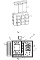
- An example of such a pressure compensated subsea electrical system 5c is schematically illustrated in Figure 6 .
- the transformer 3 and the power converter 4 may be arranged such that, in use, the transformer 3 is arranged in a horizontal position between two power converters 4.
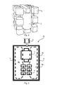
- An example of such a pressure compensated subsea electrical system 5b is schematically illustrated in Figure 4 .
- the pressure compensated subsea electrical system 5a, 5b, 5c, 5d, 5e may comprise a cooling circuit 11 through which the dielectric liquid 12 flows.
- the cooling circuit 12 encompasses at least the power converter 4 and the transformer 3. Examples of such pressure compensated subsea electrical systems 5a, 5b, 5c, 5d, 5e are schematically illustrated in Figures 3, 4 , 6 , 8 , and 9 .
- the power converter 4 and the transformer 3 may be serially connected along the cooling circuit 11. Flow of the dielectric liquid 12 inside the cooling circuit 12 may be at least partially driven by natural convection. Further, the transformer 3 and the power converter 4 may be arranged relative the cooling circuit 11 such that the flow of the dielectric liquid 12 is induced by thermal losses in the transformer 3 and is at least partially used to cool the power converter 4.
- the pressure compensated subsea electrical system may further comprise a heat exchanger 6.
- the heat exchanger 6 may be provided on an outside wall of the housing 8. An example of such a pressure compensated subsea electrical system 5d is schematically illustrated in Figure 8 .
- the heat exchanger 6 may be arranged to receive dielectric liquid 12 from the first housing portion 8a and to provide dielectric liquid 12 to the second housing portion 8b.
- the pressure compensated subsea electrical system 5a may comprise a power converter 4 and a transformer 3 in the same housing 8 where the cooling streams are mixed such that a large surface of the housing 8 can be used to partially cool the power converter 3. Further, putting the transformer 3 and the power converter 4 in a shared housing requires only one pressure compensator 2.
- FIG. 4 schematically illustrate an arrangement of a transformer 3 and components of a power converter 4 for use in a pressure compensated subsea electrical system 5b according to the embodiment of Figure 4 .
- FIG. 6 schematically illustrate an arrangement of a transformer 3 and components of a power converter 4 for use in a pressure compensated subsea electrical system 5c according to the embodiment of Figure 6 .
- transformer losses induce a natural convection flow that helps cool the power converter 4.
- the natural convention flow is according to the pressure compensated subsea electrical system 5d of present embodiment achieved by guiding the flow of the dielectric liquid 12 through ducts as formed by the separating wall 9.
- the pressure compensated subsea electrical system 5c has shared cooling cycle that includes an external heat exchanger 6. The flow of the dielectric liquid 12 is guided such that losses in the transformer 3 induce a natural convection flow through the power converter 4. Only one pressure compensator 2 is needed.
- a pressure compensated subsea electrical system 5e such that the transformer 3 and the power converter 4 each have their own separate cooling cycle and use different parts of the housing surface for heat transfer to surrounding sea water.
- the transformer 3 and the power converter 4 are separated by a separating wall 9 to keep the heat transfer between them limited.
- the through holes 10 may further be utilized for enabling an electrical connection 7 to be established between the transformer 3 and the power converter 4.
- a subsea converter may comprise any components or features of the herein disclosed pressure compensated subsea electrical systems 5a, 5b, 5c, 5d, 5e.
- a subsea converter may comprise a housing 8 filled with a dielectric liquid 12, where the housing has a first housing portion 8a and a second housing portion 8b in pressure communication with each other, where the first housing portion comprises a transformer 3, and where the second housing portion comprises a power converter 4.
- a subsea converter may further comprise a pressure compensator 2 arranged to compensate pressure inside the housing, where the pressure compensator is enabled to compensate pressure in both the first housing portion and the second housing portion.
- a subsea converter may further comprise any optional components or features of the herein disclosed pressure compensated subsea electrical systems 5a, 5b, 5c, 5d, 5e.
Landscapes
- Engineering & Computer Science (AREA)
- Microelectronics & Electronic Packaging (AREA)
- Power Engineering (AREA)
- Physics & Mathematics (AREA)
- Thermal Sciences (AREA)
- Ocean & Marine Engineering (AREA)
- Mechanical Engineering (AREA)
- General Engineering & Computer Science (AREA)
- Rectifiers (AREA)
- Mechanical Coupling Of Light Guides (AREA)
- Cable Accessories (AREA)
Abstract
Description
- The invention relates to subsea electrical systems, and particularly to a pressure compensated subsea electrical system.
- In general terms, electric subsea installations and devices usually demand high standards regarding durability, long-term functionality and independence during operation. Electric subsea installations that need to be cooled during operation, such as subsea converters, require an autonomous and durable cooling of its components. It is known to use a dielectric liquid of low compressibility such as for example mineral oil as a cooling fluid. The dielectric fluid could also be composed of natural or synthetic esters. In general terms, the dielectric fluid is used to provide a pressure compensated environment, and additionally functions as an electric insulation medium of electric components, such as capacitor units, placed in the electric installation. The tanks of power-electronic subsea equipment, such as subsea converters, are thus typically filled with oil, which acts as a combined electric insulation and cooling medium. The oil receives heat from the internal converter components and transfers it to the sea-water through the tank wall or through a heat exchanger.
- In some cases the tank is provided with a pressure compensation system, so that the internal pressure is close or equal to the external pressure. Arrangements comprising such pressure compensation systems will henceforth be called pressure compensated arrangements. The provision of a pressure compensation system imposes significantly less stress on the tank walls in comparison to tanks (such as being part of a subsea electrical system) without pressure compensation systems. For example, the pressure at 3000 meters depth is 300 bar.
- Commonly, a power converter requires several electrical connections to a transformer. Known subsea power systems typically position the power converter and the transformer in separate tanks with separate pressure compensation systems, and with wet connections for the electrical coupling.
-
Figure 1 schematically illustrates such a known pressure compensated subseaelectrical system 1a. The pressure compensated subseaelectrical system 1a comprises a first tank comprising atransformer 3 and a second tank comprising apower converter 4. The tanks are joined by a connection. Each tank is filled with adielectric fluid 12 and has its own separatepressure compensation system -
WO 2008/055515 (see, especiallyFigure 3 therein) describes a converter and a transformer, both located within one liquid-tight housing. According toWO 2008/055515 the converter is located within a further liquid-tight housing and there is consequently no fluid communication between them. -
EP2579438 (see, especiallyFigure 6 therein) discloses a converter and a transformer but does not mention fluid communication. - Known from prior art (such as in
WO 2008/055515 ) is also a pressure compensated subsea electrical system where a liquid-filled converter tank is placed inside a main vessel which also houses the transformer.Figure 2 schematically illustrates such a known pressure compensated subseaelectrical system 1b. The subseaelectrical system 1b thus comprises a first tank, filled with adielectric fluid 12, comprising atransformer 3 and having apressure compensation system 2a. The first tank in turn further comprises a second tank. The second tank, also filled with adielectric fluid 12, comprises apower converter 4 and has apressure compensation system 2b. - In general terms, the power converter has high thermal losses but requires low temperatures in order to operate efficiently. The tank wall surface is in general not sufficient to achieve the required cooling. The surface can be extended by using tank corrugations, cooling fins, or an external heat exchanger, but this increases the cost and weight of the pressure compensated subsea electrical system. On the other hand, the transformer is less sensitive to high temperatures.
- In view of the above there is still a need for an improved pressure compensated subsea electrical system comprising a transformer and a power converter.
- An object of embodiments herein is to provide efficient pressure compensated subsea electrical systems comprising a transformer and a power converter.
- Particularly, according to a first aspect there is presented a pressure compensated subsea electrical system. The pressure compensated subsea electrical system comprises a housing filled with a dielectric liquid. The housing has a first housing portion and a second housing portion in pressure communication with each other. The first housing portion comprises a transformer, and the second housing portion comprises a power converter. The pressure compensated subsea electrical system comprises a pressure compensator arranged to compensate pressure inside the housing. The pressure compensator is enabled to compensate pressure in both the first housing portion and the second housing portion.
- Having a subsea power converter and a subsea transformer placed in a shared housing filled with dielectric liquid brings a number of advantages and technical effects.
- Advantageously, only one pressure compensation system is required.
- Advantageously, there is no need for wet connections between subsea power converter and subsea transformer.
- Advantageously, the housing will have a large surface that can be used to reduce the power converter operating temperature.
- Advantageously, the housing can be extended vertically to improve natural convective flow of the dielectric liquid.
- Advantageously, this allows for temperature sensitive components to be placed in cold environment.
- Advantageously, the subsea transformer can be positioned such that transformer losses generate a natural convective flow of the dielectric liquid that helps to cool the subsea power converter. This can be achieved either by positioning the transformer above the power converter or by providing cooling channels through a dividing wall.
- Advantageously, temperature gradients within semiconductor arrangements and absolute temperatures can be reduced.
- Other objectives, features and advantages of the enclosed embodiments will be apparent from the following detailed disclosure, from the attached dependent claims as well as from the drawings.
- Generally, all terms used in the claims are to be interpreted according to their ordinary meaning in the technical field, unless explicitly defined otherwise herein. All references to "a/an/the element, apparatus, component, means, step, etc." are to be interpreted openly as referring to at least one instance of the element, apparatus, component, means, step, etc., unless explicitly stated otherwise. The steps of any method disclosed herein do not have to be performed in the exact order disclosed, unless explicitly stated.
- The invention is now described, by way of example, with reference to the accompanying drawings, in which:
-
Figures 1 and 2 schematically illustrate pressure compensated subsea electrical systems according to prior art; -
Figures 3, 4 ,6 ,8 , and9 schematically illustrate pressure compensated subsea electrical systems according to embodiments; -
Figures 5 and7 schematically illustrate arrangements of a transformer and power converter components for use in a pressure compensated subsea electrical system according to embodiments. - The invention will now be described more fully hereinafter with reference to the accompanying drawings, in which certain embodiments of the invention are shown. This invention may, however, be embodied in many different forms and should not be construed as limited to the embodiments set forth herein; rather, these embodiments are provided by way of example so that this disclosure will be thorough and complete, and will fully convey the scope of the invention to those skilled in the art. Like numbers refer to like elements throughout the description.
- Cooling systems for electric equipment, and specifically for subsea electrical systems, are used to cool down electric components, such as transformers, power converters, power electronic building blocks, semiconductor modules, connectors, and capacitor units. Such electric components generate heat that needs to be dissipated by the cooling system. The cooling systems of subsea electrical systems are usually designed in a simple manner avoiding any unnecessary parts and mechanisms. Generally it is desirable to have passive cooling systems, thus cooling systems without any driven or powered parts, such as for example without pumps, to cool down the electric equipment. In some cases natural convection is used. Cooling by natural convection uses the heat transfer from the cooling liquid to the surrounding sea water to generate circulation within the cooling system and thus within the electrical systems.
- Reference is now made to
Figures 3 to 9 .Figures 3 ,4 ,6 ,8 , and9 are cross-sectional side views illustrating pressure compensated subsea electrical systems according to embodiments.Figures 5 and7 schematically illustrate arrangements of a transformer and power converter components for use in a pressure compensated subsea electrical system according to embodiments. - In general terms, there is provided a pressure compensated subsea
electrical system - The pressure compensated subsea
electrical system housing 8. Thehousing 8 may be a tank. Thehousing 8 is filled with adielectric liquid 12. Thedielectric liquid 12 may be oil. Thehousing 8 has afirst housing portion 8a and asecond housing portion 8b. Thefirst housing portion 8a and thesecond housing portion 8b are in pressure communication with each other. The pressure communication may be fluid communication. Thefirst housing portion 8a comprises atransformer 3, and thesecond housing portion 8b comprises apower converter 4. - The pressure compensated subsea
electrical system pressure compensator 2. Thepressure compensator 2 is arranged to compensate pressure inside thehousing 8. Thepressure compensator 2 is enabled to compensate pressure in both thefirst housing portion 8a and thesecond housing portion 8b. - Particular advantages and technical effects for such a pressure compensated subsea
electrical system pressure compensator 2, is required for thefirst housing portion 8a and thesecond housing portion 8b. - In use, electrical components such as the
transformer 3 and thepower converter 4 generate heat. In general terms, for some electric components increased temperature is a common stress factor. In subsea environments, such as in subsea electrical systems, which require high reliability, the thermal stress should thus be limited to a minimum. In the electrical components energy is dissipated during operation. This energy is conducted to the outer walls of the electrical components, where it is transported to the surroundings, such as to adielectric liquid 12 surrounding the electrical components. From thedielectric liquid 12 heat is transferred to the surrounding water. In more detail, heat from thedielectric liquid 12 is transferred to the walls of thehousing 8 and from there to the water surrounding thehousing 8. Efficient cooling of the electrical components enables the electrical components hotspot temperature to be limited. - Particular optional features of such pressure compensated subsea electrical systems will now be described.
- The
first housing portion 8a may comprise atank wall 8c for transferring heat from thepower converter 4. Thetank wall 8c may comprise corrugations or cooling fins. - There may be different ways to provide the
first housing portion 8a and thesecond housing portion 8b in thehousing 8. For example thehousing 8 may further comprise at least oneseparating wall 9. The at least oneseparating wall 9 may be arranged between thepower converter 4 and thetransformer 3. Examples of such pressure compensated subseaelectrical systems Figures 8 and9 . - For such pressure compensated subsea
electrical systems hole 10 in the at least oneseparating wall 9. An example of such a pressure compensated subseaelectrical system 5e is schematically illustrated inFigure 9 . Alternatively the at least oneseparating wall 9 acts as a guide for guiding a flow of the dielectric liquid between thefirst housing portion 8a and thesecond housing portion 8b. An example of such a pressure compensated subseaelectrical system 5d is schematically illustrated inFigure 8 . - There may be different dimensions of the through hole (or through holes). For example, the at least one through hole has a total cross section of at least 1 square centimeter. Hence, the total cross section of all through holes may be at least 1 square centimeter.
- There may be different ways to provide electrical connectivity between the
transformer 3 and thepower converter 4. For example, at least one electrical connection 7 may run through the at least one throughhole 10 in the at least oneseparating wall 9 for electrically connecting thepower converter 4 and thetransformer 3. An example of such a pressure compensated subseaelectrical system 5e is schematically illustrated inFigure 9 . - There may be different ways to arrange the
power converter 4 and thetransformer 3 relative each other. For example, thetransformer 3 and thepower converter 4 may be arranged such that, in use, thetransformer 3 is arranged in a vertical position above thepower converter 4. An example of such a pressure compensated subseaelectrical system 5c is schematically illustrated inFigure 6 . For example, thetransformer 3 and thepower converter 4 may be arranged such that, in use, thetransformer 3 is arranged in a horizontal position between twopower converters 4. An example of such a pressure compensated subseaelectrical system 5b is schematically illustrated inFigure 4 . - There may be different ways to provide cooling of the
power converter 4 and thetransformer 3. For example, the pressure compensated subseaelectrical system cooling circuit 11 through which thedielectric liquid 12 flows. Thecooling circuit 12 encompasses at least thepower converter 4 and thetransformer 3. Examples of such pressure compensated subseaelectrical systems Figures 3, 4 ,6 ,8 , and9 . - There may be different ways to arrange the
power converter 4 and thetransformer 3 along the coolingcircuit 11. For example, thepower converter 4 and thetransformer 3 may be serially connected along the coolingcircuit 11. Flow of thedielectric liquid 12 inside the coolingcircuit 12 may be at least partially driven by natural convection. Further, thetransformer 3 and thepower converter 4 may be arranged relative thecooling circuit 11 such that the flow of thedielectric liquid 12 is induced by thermal losses in thetransformer 3 and is at least partially used to cool thepower converter 4. - The pressure compensated subsea electrical system may further comprise a
heat exchanger 6. Theheat exchanger 6 may be provided on an outside wall of thehousing 8. An example of such a pressure compensated subseaelectrical system 5d is schematically illustrated inFigure 8 . Theheat exchanger 6 may be arranged to receive dielectric liquid 12 from thefirst housing portion 8a and to provide dielectric liquid 12 to thesecond housing portion 8b. - Particular embodiments relating to at least some of the above disclosed pressure compensated subsea electrical systems will now be described with references to
Figures 3 to 9 . - According to a first embodiment, as illustrated in
Figure 3 , the pressure compensated subseaelectrical system 5a may comprise apower converter 4 and atransformer 3 in thesame housing 8 where the cooling streams are mixed such that a large surface of thehousing 8 can be used to partially cool thepower converter 3. Further, putting thetransformer 3 and thepower converter 4 in a shared housing requires only onepressure compensator 2. - According to a second embodiment of a pressure compensated subsea
electrical system 5b, as illustrated inFigure 4 , the constituent cells of thepower converter 4 are mounted around thetransformer 3, thereby achieving a very compact arrangement. In general terms, the herein provided embodiments create large flexibility of mechanical and electrical design so that the equipment can be made very compact. Only onepressure compensator 2 is needed.Figure 5 schematically illustrate an arrangement of atransformer 3 and components of apower converter 4 for use in a pressure compensated subseaelectrical system 5b according to the embodiment ofFigure 4 . Hence, by generalizing the embodiment ofFigure 5 there is provided an arrangement of atransformer 3 and components of apower converter 4 for use in a subsea electrical system where thetransformer 3 and the components of thepower converter 4 are arranged such that in use thetransformer 3 is arranged in a horizontal position between two power converters 4 (or between two components of one power converter). - According to a third embodiment, as illustrated in
Figure 6 , where thetransformer 3 of a pressure compensated subseaelectrical system 5c has been positioned vertically above thepower converter 4 such that transformer losses induce a natural convection flow of thedielectric liquid 12 that helps to cool thepower converter 4. Only onepressure compensator 2 is needed.Figure 7 schematically illustrate an arrangement of atransformer 3 and components of apower converter 4 for use in a pressure compensated subseaelectrical system 5c according to the embodiment ofFigure 6 . Hence, by generalizing the embodiment ofFigure 7 there is provided an arrangement of atransformer 3 and components of apower converter 4 for use in a subsea electrical system where thetransformer 3 and the components of thepower converter 4 are arranged such that in use thetransformer 3 is arranged in a vertical position above (the components of) thepower converter 4. - According to a fourth embodiment, as illustrated in
Figure 8 , transformer losses induce a natural convection flow that helps cool thepower converter 4. In contrast to the embodiment ofFigure 6 , the natural convention flow is according to the pressure compensated subseaelectrical system 5d of present embodiment achieved by guiding the flow of thedielectric liquid 12 through ducts as formed by the separatingwall 9. Further, according to the present embodiment the pressure compensated subseaelectrical system 5c has shared cooling cycle that includes anexternal heat exchanger 6. The flow of thedielectric liquid 12 is guided such that losses in thetransformer 3 induce a natural convection flow through thepower converter 4. Only onepressure compensator 2 is needed. - According to a fifth embodiment, as illustrated in
Figure 9 , it is also possible to design a pressure compensated subseaelectrical system 5e such that thetransformer 3 and thepower converter 4 each have their own separate cooling cycle and use different parts of the housing surface for heat transfer to surrounding sea water. Thetransformer 3 and thepower converter 4 are separated by a separatingwall 9 to keep the heat transfer between them limited. There could be small throughholes 10 in the separatingwall 9 so that thedielectric liquid 12 is in pressure communication and only one pressure compensator is needed 12. The through holes 10 may further be utilized for enabling an electrical connection 7 to be established between thetransformer 3 and thepower converter 4. - The invention has mainly been described above with reference to a few embodiments. However, as is readily appreciated by a person skilled in the art, other embodiments than the ones disclosed above are equally possible within the scope of the invention, as defined by the appended patent claims. For example, although oil has been used as an example of the
dielectric liquid 12, it is understood that any suitable dielectric liquid 12 could be used. For example, although reference has been made to asingle power converter 4, any of the herein disclosed pressure compensated subseaelectrical systems power converters 4. - Further, although reference has been made to a pressure compensated subsea
electrical system electrical systems housing 8 filled with adielectric liquid 12, where the housing has afirst housing portion 8a and asecond housing portion 8b in pressure communication with each other, where the first housing portion comprises atransformer 3, and where the second housing portion comprises apower converter 4. Thus, a subsea converter may further comprise apressure compensator 2 arranged to compensate pressure inside the housing, where the pressure compensator is enabled to compensate pressure in both the first housing portion and the second housing portion. Thus, a subsea converter may further comprise any optional components or features of the herein disclosed pressure compensated subseaelectrical systems
Claims (15)
- A pressure compensated subsea electrical system (5a, 5b, 5c, 5d, 5e), comprising:a housing (8) filled with a dielectric liquid (12), the housing having a first housing portion (8a) and a second housing portion (8b) in pressure communication with each other, the first housing portion comprising a transformer (3), and the second housing portion comprising a power converter (4); anda pressure compensator (2) arranged to compensate pressure inside the housing, wherein the pressure compensator is enabled to compensate pressure in both the first housing portion and the second housing portion.
- The pressure compensated subsea electrical system according to claim 1, wherein the pressure communication is fluid communication.
- The pressure compensated subsea electrical system according to claim 1 or 2, wherein the first housing portion comprises a tank wall (8c) for transferring heat from the power converter.
- The pressure compensated subsea electrical system according to any one of claims 1 to 3, wherein the housing further comprises:at least one separating wall (9) arranged between the power converter and the transformer.
- The pressure compensated subsea electrical system according to claim 4, wherein the pressure communication consists of at least one through hole (10) in the at least one separating wall.
- The pressure compensated subsea electrical system according to claim 6, wherein the at least one through hole has a total cross section of at least 1 square centimeter.
- The pressure compensated subsea electrical system according to claim 5 or 6, wherein at least one electrical connection (7) runs through the at least one through hole in the at least one separating wall for electrically connecting the power converter and the transformer.
- The pressure compensated subsea electrical system according to any one of claim 3 to 7, wherein the tank wall comprises corrugations or cooling fins.
- The pressure compensated subsea electrical system according to any one of claims 1 to 8, further comprising:a cooling circuit (11) through which the dielectric liquid flows, the cooling circuit encompassing the power converter and the transformer.
- The pressure compensated subsea electrical system according to claim 9, wherein the power converter and the transformer are serially connected along the cooling circuit.
- The pressure compensated subsea electrical system according to claim 10, wherein flow of the dielectric liquid inside the cooling circuit is driven at least partially by natural convection.
- The pressure compensated subsea electrical system according to claim 10 or 11, wherein the transformer and the power converter are arranged relative the cooling circuit such that the flow of the dielectric liquid is induced by thermal losses in the transformer and is at least partially used to cool the power converter.
- The pressure compensated subsea electrical system according to any one of claims 1 to 12, wherein the transformer and the power converter are arranged such that in use the transformer is arranged in a vertical position above the power converter.
- The pressure compensated subsea electrical system according to any one of claims 1 to 13, further comprising:a heat exchanger (6), the heat exchanger being provided on an outside wall of the housing.
- The pressure compensated subsea electrical system according to claim 14, wherein the heat exchanger is arranged to receive dielectric liquid from the first housing portion and to provide dielectric liquid to the second housing portion.
Priority Applications (10)
| Application Number | Priority Date | Filing Date | Title |
|---|---|---|---|
| EP14181874.0A EP2988311B1 (en) | 2014-08-22 | 2014-08-22 | Pressure compensated subsea electrical system |
| DK14181874.0T DK2988311T3 (en) | 2014-08-22 | 2014-08-22 | Pressure compensated subsea electrical system |
| CN201580045533.4A CN106605457B (en) | 2014-08-22 | 2015-08-10 | Pressure compensated underwater electrical system |
| RU2017109375A RU2680722C2 (en) | 2014-08-22 | 2015-08-10 | Pressure compensated subsea electrical system |
| AU2015306293A AU2015306293B2 (en) | 2014-08-22 | 2015-08-10 | Pressure compensated subsea electrical system |
| US15/504,222 US10244650B2 (en) | 2014-08-22 | 2015-08-10 | Pressure compensated subsea electrical system |
| PCT/EP2015/068376 WO2016026729A1 (en) | 2014-08-22 | 2015-08-10 | Pressure compensated subsea electrical system |
| MX2017002292A MX364549B (en) | 2014-08-22 | 2015-08-10 | Pressure compensated subsea electrical system. |
| BR112017003210-4A BR112017003210B1 (en) | 2014-08-22 | 2015-08-10 | Subsea electrical system with pressure compensated |
| CA2958928A CA2958928C (en) | 2014-08-22 | 2015-08-10 | Pressure compensated subsea electrical system |
Applications Claiming Priority (1)
| Application Number | Priority Date | Filing Date | Title |
|---|---|---|---|
| EP14181874.0A EP2988311B1 (en) | 2014-08-22 | 2014-08-22 | Pressure compensated subsea electrical system |
Publications (2)
| Publication Number | Publication Date |
|---|---|
| EP2988311A1 true EP2988311A1 (en) | 2016-02-24 |
| EP2988311B1 EP2988311B1 (en) | 2021-04-28 |
Family
ID=51399526
Family Applications (1)
| Application Number | Title | Priority Date | Filing Date |
|---|---|---|---|
| EP14181874.0A Active EP2988311B1 (en) | 2014-08-22 | 2014-08-22 | Pressure compensated subsea electrical system |
Country Status (10)
| Country | Link |
|---|---|
| US (1) | US10244650B2 (en) |
| EP (1) | EP2988311B1 (en) |
| CN (1) | CN106605457B (en) |
| AU (1) | AU2015306293B2 (en) |
| BR (1) | BR112017003210B1 (en) |
| CA (1) | CA2958928C (en) |
| DK (1) | DK2988311T3 (en) |
| MX (1) | MX364549B (en) |
| RU (1) | RU2680722C2 (en) |
| WO (1) | WO2016026729A1 (en) |
Cited By (8)
| Publication number | Priority date | Publication date | Assignee | Title |
|---|---|---|---|---|
| US20160150671A1 (en) * | 2013-07-09 | 2016-05-26 | Abb Technology Ltd | Subsea Unit With Cooling Of Electronic Devices |
| US9699939B2 (en) * | 2014-06-24 | 2017-07-04 | David Lane Smith | System and method for fluid cooling of electronic devices installed in a sealed enclosure |
| EP3404198A1 (en) * | 2017-05-19 | 2018-11-21 | ABB Schweiz AG | A cooling arrangement of a subsea installation |
| WO2019115155A1 (en) * | 2017-12-15 | 2019-06-20 | Siemens Aktiengesellschaft | Electrical device having an internal circulation unit |
| US10455730B2 (en) | 2018-03-08 | 2019-10-22 | Saudi Arabian Oil Company | Thermal control system |
| US11191186B2 (en) | 2014-06-24 | 2021-11-30 | David Lane Smith | System and method for fluid cooling of electronic devices installed in an enclosure |
| US11448473B2 (en) * | 2019-04-23 | 2022-09-20 | Abb Schweiz Ag | Heat exchanging arrangement and subsea electronic system |
| US11744041B2 (en) | 2014-06-24 | 2023-08-29 | David Lane Smith | System and method for fluid cooling of electronic devices installed in an enclosure |
Families Citing this family (21)
| Publication number | Priority date | Publication date | Assignee | Title |
|---|---|---|---|---|
| US10026537B2 (en) * | 2015-02-25 | 2018-07-17 | Onesubsea Ip Uk Limited | Fault tolerant subsea transformer |
| NO343424B1 (en) * | 2015-08-26 | 2019-03-04 | Fmc Kongsberg Subsea As | Combined Subsea Transformer and compensating HV Reactor |
| NL2015841B1 (en) * | 2015-11-23 | 2017-06-07 | Aecorsis B V | A device comprising heat producing components with liquid submersion cooling. |
| JP6211119B2 (en) * | 2016-02-26 | 2017-10-11 | 三菱電機株式会社 | Current control device |
| GB201619987D0 (en) | 2016-11-25 | 2017-01-11 | Iceotope Ltd | Fluid cooling system |
| EP3343575B1 (en) * | 2016-12-28 | 2020-03-18 | ABB Schweiz AG | A pressure compensator of a subsea installation |
| US11716030B2 (en) * | 2017-03-02 | 2023-08-01 | Massachusetts Institute Of Technology | Variable inverter-rectifier-transformer |
| CN107369523A (en) * | 2017-08-30 | 2017-11-21 | 华中科技大学 | A kind of underwater transformer of Natural Heat Convection formula |
| EP3753048B1 (en) * | 2018-04-03 | 2023-11-22 | Siemens Energy Global GmbH & Co. KG | Circuit arrangement, power converter module, and method for operating the power converter module |
| JP7180130B2 (en) * | 2018-06-07 | 2022-11-30 | 富士通株式会社 | Immersion bath |
| US10609839B1 (en) | 2018-09-28 | 2020-03-31 | Liquidcool Solutions, Inc. | Liquid submersion cooled electronic systems and devices |
| JP7332851B2 (en) * | 2018-12-28 | 2023-08-24 | 富士通株式会社 | cooling system |
| TWM589293U (en) * | 2019-08-23 | 2020-01-11 | 緯創資通股份有限公司 | Heat dissipation module and electronic device |
| CN110534293A (en) * | 2019-09-20 | 2019-12-03 | 徐州科奥电气有限公司 | A kind of fault-tolerant underwater transformer |
| EP3908092B1 (en) | 2020-05-04 | 2023-03-15 | ABB Schweiz AG | Subsea power module |
| EP3934043A1 (en) * | 2020-06-30 | 2022-01-05 | ABB Schweiz AG | Arrangement for overvoltage protection of subsea electrical apparatus |
| US11606878B2 (en) | 2021-04-09 | 2023-03-14 | Microsoft Technology Licensing, Llc | Systems and methods for immersion-cooled datacenters |
| US11533829B2 (en) | 2021-04-09 | 2022-12-20 | Microsoft Technology Licensing, Llc | Systems and methods for immersion-cooled datacenters |
| EP4195226A1 (en) | 2021-12-13 | 2023-06-14 | Abb Schweiz Ag | A subsea substation system |
| NO347837B1 (en) * | 2022-09-05 | 2024-04-15 | Orca Connex As | System and method for optimised cooling and simplified handling of data processing equipment |
| WO2024237947A1 (en) * | 2023-05-16 | 2024-11-21 | MTS IP Holdings Ltd | Bellows for immersion cooling |
Citations (7)
| Publication number | Priority date | Publication date | Assignee | Title |
|---|---|---|---|---|
| EP0025794A1 (en) | 1979-03-26 | 1981-04-01 | Gen Electric | Method and apparatus for measuring antibody levels. |
| WO2008000055A1 (en) | 2006-06-30 | 2008-01-03 | Vx Technologies Inc. | Methods for simultaneous multi-set point matching |
| WO2008055515A1 (en) | 2006-11-06 | 2008-05-15 | Siemens Aktiengesellschaft | Variable speed drive for subsea applications |
| EP2487327A1 (en) * | 2011-02-09 | 2012-08-15 | Siemens Aktiengesellschaft | Subsea electronic system |
| EP2666956A1 (en) * | 2012-05-21 | 2013-11-27 | ABB Technology AG | A modular electric system located under water |
| EP2717401A1 (en) * | 2012-10-05 | 2014-04-09 | Siemens Aktiengesellschaft | Subsea electrical power system |
| WO2014071985A1 (en) * | 2012-11-09 | 2014-05-15 | Abb Technology Ltd | Subsea unit comprising a two-phase cooling system and a subsea power system comprising such a subsea unit |
Family Cites Families (36)
| Publication number | Priority date | Publication date | Assignee | Title |
|---|---|---|---|---|
| US2023100A (en) * | 1934-07-25 | 1935-12-03 | Westinghouse Electric & Mfg Co | Electrical conversion system |
| BE514321A (en) * | 1951-09-28 | 1952-10-15 | Siemens Reiniger Werke Ag | high-voltage x-ray unit |
| US3091722A (en) * | 1961-06-21 | 1963-05-28 | Sylvania Electric Prod | Electronic assembly packaging |
| GB1035905A (en) * | 1961-12-06 | 1966-07-13 | Plessey Co Ltd | Improvements in cooling systems |
| US3564386A (en) * | 1968-12-27 | 1971-02-16 | Westinghouse Electric Corp | Power supply for converting high voltage alternating current into high voltage direct current |
| DE2255646C3 (en) * | 1972-11-14 | 1979-03-08 | Danfoss A/S, Nordborg (Daenemark) | oil-cooled electrical device |
| DE2423929B1 (en) * | 1974-05-16 | 1975-11-20 | Siemens Ag, 1000 Berlin Und 8000 Muenchen | High voltage generator for an X-ray diagnostic apparatus |
| JP2660875B2 (en) * | 1990-06-12 | 1997-10-08 | 松下電器産業株式会社 | Gas laser device |
| US5305184A (en) * | 1992-12-16 | 1994-04-19 | Ibm Corporation | Method and apparatus for immersion cooling or an electronic board |
| US5373417A (en) * | 1994-02-28 | 1994-12-13 | Motorola, Inc. | Liquid-cooled circuit package with micro-bellows for controlling expansion |
| JPH09271178A (en) * | 1996-03-29 | 1997-10-14 | Daihen Corp | Power conversion equipment |
| NO313068B1 (en) | 2000-11-14 | 2002-08-05 | Abb As | Underwater transformer - distribution system with a first and a second chamber |
| DE10127276B4 (en) | 2001-05-28 | 2004-06-03 | Siemens Ag | Underwater transformer and method for adjusting the pressure in the outer vessel of an underwater transformer |
| DE202004003644U1 (en) * | 2004-03-09 | 2004-05-13 | Kinder, Georg | Cooling system for an electronic device, in particular a computer |
| US20070034360A1 (en) * | 2005-06-08 | 2007-02-15 | Hall Jack P | High performance cooling assembly for electronics |
| US7847189B2 (en) * | 2005-07-01 | 2010-12-07 | Siemens Aktiengesellschaft | Electrical Component |
| US20080302115A1 (en) | 2007-06-08 | 2008-12-11 | Coda Octopus Group, Inc. | Combined pressure compensator and cooling unit |
| EP2169690B1 (en) | 2008-09-24 | 2012-08-29 | ABB Technology AG | Pressure compensator |
| FR2943488B1 (en) | 2009-03-23 | 2011-04-22 | Converteam Technology Ltd | ELECTRICAL MODULE FOR IMMERSION IN WATER |
| US8000102B2 (en) * | 2009-08-20 | 2011-08-16 | Babcock & Wilcox Power Generation Group, Inc. | Apparatus and arrangement for housing voltage conditioning and filtering circuitry components for an electrostatic precipitator |
| CN101753037A (en) | 2009-09-11 | 2010-06-23 | 上海东沪医用设备有限公司 | High voltage generation device of medical high-frequency high voltage generator |
| EP2487326B1 (en) * | 2011-02-09 | 2018-03-28 | Siemens Aktiengesellschaft | Subsea electronic system |
| EP2571034A1 (en) | 2011-09-19 | 2013-03-20 | Siemens Aktiengesellschaft | Subsea transformer enclosure |
| EP2579438A1 (en) | 2011-10-06 | 2013-04-10 | Siemens Aktiengesellschaft | Power cell for deepwater application |
| EP2610881B1 (en) * | 2011-12-28 | 2014-04-30 | Siemens Aktiengesellschaft | Pressure compensator for a subsea device |
| WO2013123270A1 (en) * | 2012-02-16 | 2013-08-22 | Allergan, Inc. | Compositions and improved soft tissue replacement methods |
| NO335863B1 (en) * | 2012-02-21 | 2015-03-09 | Aker Subsea As | Direct electric heating assembly for long layouts |
| CN102623138A (en) * | 2012-04-18 | 2012-08-01 | 南京电气(集团)有限责任公司 | Internal pressure compensation device for oil-impregnated paper insulating sleeve |
| EP2803813B1 (en) * | 2013-05-16 | 2019-02-27 | ABB Schweiz AG | A subsea unit with conduction and convection cooling |
| EP2824275B1 (en) * | 2013-07-09 | 2015-09-16 | ABB Technology Ltd | Subsea unit with cooling of electronic devices |
| US9777966B2 (en) * | 2014-01-30 | 2017-10-03 | General Electric Company | System for cooling heat generating electrically active components for subsea applications |
| EP2928275A1 (en) * | 2014-04-04 | 2015-10-07 | ABB Technology Ltd | Arrangement for cooling components of a subsea electric system |
| CN104183364B (en) * | 2014-06-23 | 2016-10-05 | 上海联影医疗科技有限公司 | High pressure generator transformer oil tank |
| NO2988580T3 (en) * | 2014-08-22 | 2018-03-10 | ||
| US10026537B2 (en) * | 2015-02-25 | 2018-07-17 | Onesubsea Ip Uk Limited | Fault tolerant subsea transformer |
| US10130009B2 (en) * | 2017-03-15 | 2018-11-13 | American Superconductor Corporation | Natural convection cooling for power electronics systems having discrete power dissipation components |
-
2014
- 2014-08-22 EP EP14181874.0A patent/EP2988311B1/en active Active
- 2014-08-22 DK DK14181874.0T patent/DK2988311T3/en active
-
2015
- 2015-08-10 BR BR112017003210-4A patent/BR112017003210B1/en active IP Right Grant
- 2015-08-10 WO PCT/EP2015/068376 patent/WO2016026729A1/en not_active Ceased
- 2015-08-10 RU RU2017109375A patent/RU2680722C2/en active
- 2015-08-10 US US15/504,222 patent/US10244650B2/en active Active
- 2015-08-10 AU AU2015306293A patent/AU2015306293B2/en not_active Ceased
- 2015-08-10 CA CA2958928A patent/CA2958928C/en active Active
- 2015-08-10 CN CN201580045533.4A patent/CN106605457B/en active Active
- 2015-08-10 MX MX2017002292A patent/MX364549B/en active IP Right Grant
Patent Citations (8)
| Publication number | Priority date | Publication date | Assignee | Title |
|---|---|---|---|---|
| EP0025794A1 (en) | 1979-03-26 | 1981-04-01 | Gen Electric | Method and apparatus for measuring antibody levels. |
| WO2008000055A1 (en) | 2006-06-30 | 2008-01-03 | Vx Technologies Inc. | Methods for simultaneous multi-set point matching |
| WO2008055515A1 (en) | 2006-11-06 | 2008-05-15 | Siemens Aktiengesellschaft | Variable speed drive for subsea applications |
| US20100139544A1 (en) * | 2006-11-06 | 2010-06-10 | Boe Ove | Variable speed drive for subsea applications |
| EP2487327A1 (en) * | 2011-02-09 | 2012-08-15 | Siemens Aktiengesellschaft | Subsea electronic system |
| EP2666956A1 (en) * | 2012-05-21 | 2013-11-27 | ABB Technology AG | A modular electric system located under water |
| EP2717401A1 (en) * | 2012-10-05 | 2014-04-09 | Siemens Aktiengesellschaft | Subsea electrical power system |
| WO2014071985A1 (en) * | 2012-11-09 | 2014-05-15 | Abb Technology Ltd | Subsea unit comprising a two-phase cooling system and a subsea power system comprising such a subsea unit |
Cited By (8)
| Publication number | Priority date | Publication date | Assignee | Title |
|---|---|---|---|---|
| US20160150671A1 (en) * | 2013-07-09 | 2016-05-26 | Abb Technology Ltd | Subsea Unit With Cooling Of Electronic Devices |
| US9699939B2 (en) * | 2014-06-24 | 2017-07-04 | David Lane Smith | System and method for fluid cooling of electronic devices installed in a sealed enclosure |
| US11191186B2 (en) | 2014-06-24 | 2021-11-30 | David Lane Smith | System and method for fluid cooling of electronic devices installed in an enclosure |
| US11744041B2 (en) | 2014-06-24 | 2023-08-29 | David Lane Smith | System and method for fluid cooling of electronic devices installed in an enclosure |
| EP3404198A1 (en) * | 2017-05-19 | 2018-11-21 | ABB Schweiz AG | A cooling arrangement of a subsea installation |
| WO2019115155A1 (en) * | 2017-12-15 | 2019-06-20 | Siemens Aktiengesellschaft | Electrical device having an internal circulation unit |
| US10455730B2 (en) | 2018-03-08 | 2019-10-22 | Saudi Arabian Oil Company | Thermal control system |
| US11448473B2 (en) * | 2019-04-23 | 2022-09-20 | Abb Schweiz Ag | Heat exchanging arrangement and subsea electronic system |
Also Published As
| Publication number | Publication date |
|---|---|
| RU2680722C2 (en) | 2019-02-26 |
| EP2988311B1 (en) | 2021-04-28 |
| US10244650B2 (en) | 2019-03-26 |
| BR112017003210B1 (en) | 2022-02-01 |
| MX364549B (en) | 2019-04-30 |
| CA2958928C (en) | 2018-10-23 |
| MX2017002292A (en) | 2017-08-21 |
| RU2017109375A (en) | 2018-09-24 |
| CN106605457A (en) | 2017-04-26 |
| CA2958928A1 (en) | 2016-02-25 |
| CN106605457B (en) | 2019-12-17 |
| RU2017109375A3 (en) | 2018-09-24 |
| DK2988311T3 (en) | 2021-07-26 |
| BR112017003210A2 (en) | 2017-11-28 |
| AU2015306293B2 (en) | 2018-04-05 |
| US20170280577A1 (en) | 2017-09-28 |
| AU2015306293A1 (en) | 2017-03-02 |
| WO2016026729A1 (en) | 2016-02-25 |
Similar Documents
| Publication | Publication Date | Title |
|---|---|---|
| EP2988311B1 (en) | Pressure compensated subsea electrical system | |
| EP3127409B1 (en) | Arrangement for cooling components of a subsea electric system | |
| EP2825008B1 (en) | Oil cooling configuration for subsea converter | |
| EP2962536B1 (en) | Cooling system with redundancy | |
| CN110352487B (en) | Heat Exchangers and Subsea Electronic Systems | |
| US9777966B2 (en) | System for cooling heat generating electrically active components for subsea applications | |
| US10879150B2 (en) | Arrangement for subsea cooling of semiconductor modules | |
| EP2988579B1 (en) | Oil cooling configuration for an electronic subsea system | |
| EP2919571B1 (en) | Arrangement for subsea cooling of electric equipment | |
| EP3051243A1 (en) | Arrangement for subsea cooling of electric equipment | |
| EP3155883B1 (en) | Subsea cooling assembly | |
| EP2679765A1 (en) | Subsea unit comprising a two-phase cooling system | |
| EP2988580B1 (en) | A subsea unit enclosing an electrically insulating liquid and a thermally conducting liquid | |
| SE1400342A1 (en) | Arrangement for cooling electrical components of a subsea electric system | |
| EP2846617A1 (en) | Cooling arrangement for power electronics building blocks | |
| US9774183B2 (en) | Methods and systems for subsea direct current power distribution | |
| EP3211980A1 (en) | Arrangement for subsea cooling of power electronic cells | |
| EP3382312B1 (en) | A subsea heat exchanger |
Legal Events
| Date | Code | Title | Description |
|---|---|---|---|
| PUAI | Public reference made under article 153(3) epc to a published international application that has entered the european phase |
Free format text: ORIGINAL CODE: 0009012 |
|
| AK | Designated contracting states |
Kind code of ref document: A1 Designated state(s): AL AT BE BG CH CY CZ DE DK EE ES FI FR GB GR HR HU IE IS IT LI LT LU LV MC MK MT NL NO PL PT RO RS SE SI SK SM TR |
|
| AX | Request for extension of the european patent |
Extension state: BA ME |
|
| 17P | Request for examination filed |
Effective date: 20160824 |
|
| RBV | Designated contracting states (corrected) |
Designated state(s): AL AT BE BG CH CY CZ DE DK EE ES FI FR GB GR HR HU IE IS IT LI LT LU LV MC MK MT NL NO PL PT RO RS SE SI SK SM TR |
|
| RAP1 | Party data changed (applicant data changed or rights of an application transferred) |
Owner name: ABB SCHWEIZ AG |
|
| STAA | Information on the status of an ep patent application or granted ep patent |
Free format text: STATUS: EXAMINATION IS IN PROGRESS |
|
| 17Q | First examination report despatched |
Effective date: 20170616 |
|
| GRAP | Despatch of communication of intention to grant a patent |
Free format text: ORIGINAL CODE: EPIDOSNIGR1 |
|
| STAA | Information on the status of an ep patent application or granted ep patent |
Free format text: STATUS: GRANT OF PATENT IS INTENDED |
|
| INTG | Intention to grant announced |
Effective date: 20201126 |
|
| GRAS | Grant fee paid |
Free format text: ORIGINAL CODE: EPIDOSNIGR3 |
|
| GRAA | (expected) grant |
Free format text: ORIGINAL CODE: 0009210 |
|
| STAA | Information on the status of an ep patent application or granted ep patent |
Free format text: STATUS: THE PATENT HAS BEEN GRANTED |
|
| AK | Designated contracting states |
Kind code of ref document: B1 Designated state(s): AL AT BE BG CH CY CZ DE DK EE ES FI FR GB GR HR HU IE IS IT LI LT LU LV MC MK MT NL NO PL PT RO RS SE SI SK SM TR |
|
| REG | Reference to a national code |
Ref country code: GB Ref legal event code: FG4D |
|
| REG | Reference to a national code |
Ref country code: CH Ref legal event code: EP |
|
| REG | Reference to a national code |
Ref country code: DE Ref legal event code: R096 Ref document number: 602014076941 Country of ref document: DE |
|
| REG | Reference to a national code |
Ref country code: AT Ref legal event code: REF Ref document number: 1388027 Country of ref document: AT Kind code of ref document: T Effective date: 20210515 |
|
| REG | Reference to a national code |
Ref country code: IE Ref legal event code: FG4D |
|
| REG | Reference to a national code |
Ref country code: DK Ref legal event code: T3 Effective date: 20210720 |
|
| REG | Reference to a national code |
Ref country code: LT Ref legal event code: MG9D |
|
| REG | Reference to a national code |
Ref country code: NO Ref legal event code: T2 Effective date: 20210428 |
|
| REG | Reference to a national code |
Ref country code: AT Ref legal event code: MK05 Ref document number: 1388027 Country of ref document: AT Kind code of ref document: T Effective date: 20210428 |
|
| PG25 | Lapsed in a contracting state [announced via postgrant information from national office to epo] |
Ref country code: HR Free format text: LAPSE BECAUSE OF FAILURE TO SUBMIT A TRANSLATION OF THE DESCRIPTION OR TO PAY THE FEE WITHIN THE PRESCRIBED TIME-LIMIT Effective date: 20210428 Ref country code: FI Free format text: LAPSE BECAUSE OF FAILURE TO SUBMIT A TRANSLATION OF THE DESCRIPTION OR TO PAY THE FEE WITHIN THE PRESCRIBED TIME-LIMIT Effective date: 20210428 Ref country code: LT Free format text: LAPSE BECAUSE OF FAILURE TO SUBMIT A TRANSLATION OF THE DESCRIPTION OR TO PAY THE FEE WITHIN THE PRESCRIBED TIME-LIMIT Effective date: 20210428 Ref country code: NL Free format text: LAPSE BECAUSE OF FAILURE TO SUBMIT A TRANSLATION OF THE DESCRIPTION OR TO PAY THE FEE WITHIN THE PRESCRIBED TIME-LIMIT Effective date: 20210428 Ref country code: AT Free format text: LAPSE BECAUSE OF FAILURE TO SUBMIT A TRANSLATION OF THE DESCRIPTION OR TO PAY THE FEE WITHIN THE PRESCRIBED TIME-LIMIT Effective date: 20210428 Ref country code: BG Free format text: LAPSE BECAUSE OF FAILURE TO SUBMIT A TRANSLATION OF THE DESCRIPTION OR TO PAY THE FEE WITHIN THE PRESCRIBED TIME-LIMIT Effective date: 20210728 |
|
| PG25 | Lapsed in a contracting state [announced via postgrant information from national office to epo] |
Ref country code: LV Free format text: LAPSE BECAUSE OF FAILURE TO SUBMIT A TRANSLATION OF THE DESCRIPTION OR TO PAY THE FEE WITHIN THE PRESCRIBED TIME-LIMIT Effective date: 20210428 Ref country code: GR Free format text: LAPSE BECAUSE OF FAILURE TO SUBMIT A TRANSLATION OF THE DESCRIPTION OR TO PAY THE FEE WITHIN THE PRESCRIBED TIME-LIMIT Effective date: 20210729 Ref country code: IS Free format text: LAPSE BECAUSE OF FAILURE TO SUBMIT A TRANSLATION OF THE DESCRIPTION OR TO PAY THE FEE WITHIN THE PRESCRIBED TIME-LIMIT Effective date: 20210828 Ref country code: PL Free format text: LAPSE BECAUSE OF FAILURE TO SUBMIT A TRANSLATION OF THE DESCRIPTION OR TO PAY THE FEE WITHIN THE PRESCRIBED TIME-LIMIT Effective date: 20210428 Ref country code: PT Free format text: LAPSE BECAUSE OF FAILURE TO SUBMIT A TRANSLATION OF THE DESCRIPTION OR TO PAY THE FEE WITHIN THE PRESCRIBED TIME-LIMIT Effective date: 20210830 Ref country code: ES Free format text: LAPSE BECAUSE OF FAILURE TO SUBMIT A TRANSLATION OF THE DESCRIPTION OR TO PAY THE FEE WITHIN THE PRESCRIBED TIME-LIMIT Effective date: 20210428 Ref country code: SE Free format text: LAPSE BECAUSE OF FAILURE TO SUBMIT A TRANSLATION OF THE DESCRIPTION OR TO PAY THE FEE WITHIN THE PRESCRIBED TIME-LIMIT Effective date: 20210428 Ref country code: RS Free format text: LAPSE BECAUSE OF FAILURE TO SUBMIT A TRANSLATION OF THE DESCRIPTION OR TO PAY THE FEE WITHIN THE PRESCRIBED TIME-LIMIT Effective date: 20210428 |
|
| REG | Reference to a national code |
Ref country code: NL Ref legal event code: MP Effective date: 20210428 |
|
| PG25 | Lapsed in a contracting state [announced via postgrant information from national office to epo] |
Ref country code: SM Free format text: LAPSE BECAUSE OF FAILURE TO SUBMIT A TRANSLATION OF THE DESCRIPTION OR TO PAY THE FEE WITHIN THE PRESCRIBED TIME-LIMIT Effective date: 20210428 Ref country code: SK Free format text: LAPSE BECAUSE OF FAILURE TO SUBMIT A TRANSLATION OF THE DESCRIPTION OR TO PAY THE FEE WITHIN THE PRESCRIBED TIME-LIMIT Effective date: 20210428 Ref country code: EE Free format text: LAPSE BECAUSE OF FAILURE TO SUBMIT A TRANSLATION OF THE DESCRIPTION OR TO PAY THE FEE WITHIN THE PRESCRIBED TIME-LIMIT Effective date: 20210428 Ref country code: CZ Free format text: LAPSE BECAUSE OF FAILURE TO SUBMIT A TRANSLATION OF THE DESCRIPTION OR TO PAY THE FEE WITHIN THE PRESCRIBED TIME-LIMIT Effective date: 20210428 Ref country code: RO Free format text: LAPSE BECAUSE OF FAILURE TO SUBMIT A TRANSLATION OF THE DESCRIPTION OR TO PAY THE FEE WITHIN THE PRESCRIBED TIME-LIMIT Effective date: 20210428 |
|
| REG | Reference to a national code |
Ref country code: DE Ref legal event code: R097 Ref document number: 602014076941 Country of ref document: DE |
|
| PLBE | No opposition filed within time limit |
Free format text: ORIGINAL CODE: 0009261 |
|
| STAA | Information on the status of an ep patent application or granted ep patent |
Free format text: STATUS: NO OPPOSITION FILED WITHIN TIME LIMIT |
|
| REG | Reference to a national code |
Ref country code: CH Ref legal event code: PL |
|
| PG25 | Lapsed in a contracting state [announced via postgrant information from national office to epo] |
Ref country code: MC Free format text: LAPSE BECAUSE OF FAILURE TO SUBMIT A TRANSLATION OF THE DESCRIPTION OR TO PAY THE FEE WITHIN THE PRESCRIBED TIME-LIMIT Effective date: 20210428 |
|
| 26N | No opposition filed |
Effective date: 20220131 |
|
| REG | Reference to a national code |
Ref country code: BE Ref legal event code: MM Effective date: 20210831 |
|
| PG25 | Lapsed in a contracting state [announced via postgrant information from national office to epo] |
Ref country code: LI Free format text: LAPSE BECAUSE OF NON-PAYMENT OF DUE FEES Effective date: 20210831 Ref country code: CH Free format text: LAPSE BECAUSE OF NON-PAYMENT OF DUE FEES Effective date: 20210831 |
|
| PG25 | Lapsed in a contracting state [announced via postgrant information from national office to epo] |
Ref country code: IS Free format text: LAPSE BECAUSE OF FAILURE TO SUBMIT A TRANSLATION OF THE DESCRIPTION OR TO PAY THE FEE WITHIN THE PRESCRIBED TIME-LIMIT Effective date: 20210828 Ref country code: LU Free format text: LAPSE BECAUSE OF NON-PAYMENT OF DUE FEES Effective date: 20210822 Ref country code: AL Free format text: LAPSE BECAUSE OF FAILURE TO SUBMIT A TRANSLATION OF THE DESCRIPTION OR TO PAY THE FEE WITHIN THE PRESCRIBED TIME-LIMIT Effective date: 20210428 |
|
| PG25 | Lapsed in a contracting state [announced via postgrant information from national office to epo] |
Ref country code: IE Free format text: LAPSE BECAUSE OF NON-PAYMENT OF DUE FEES Effective date: 20210822 Ref country code: BE Free format text: LAPSE BECAUSE OF NON-PAYMENT OF DUE FEES Effective date: 20210831 |
|
| PG25 | Lapsed in a contracting state [announced via postgrant information from national office to epo] |
Ref country code: HU Free format text: LAPSE BECAUSE OF FAILURE TO SUBMIT A TRANSLATION OF THE DESCRIPTION OR TO PAY THE FEE WITHIN THE PRESCRIBED TIME-LIMIT; INVALID AB INITIO Effective date: 20140822 |
|
| PG25 | Lapsed in a contracting state [announced via postgrant information from national office to epo] |
Ref country code: CY Free format text: LAPSE BECAUSE OF FAILURE TO SUBMIT A TRANSLATION OF THE DESCRIPTION OR TO PAY THE FEE WITHIN THE PRESCRIBED TIME-LIMIT Effective date: 20210428 |
|
| PG25 | Lapsed in a contracting state [announced via postgrant information from national office to epo] |
Ref country code: MK Free format text: LAPSE BECAUSE OF FAILURE TO SUBMIT A TRANSLATION OF THE DESCRIPTION OR TO PAY THE FEE WITHIN THE PRESCRIBED TIME-LIMIT Effective date: 20210428 |
|
| PG25 | Lapsed in a contracting state [announced via postgrant information from national office to epo] |
Ref country code: TR Free format text: LAPSE BECAUSE OF FAILURE TO SUBMIT A TRANSLATION OF THE DESCRIPTION OR TO PAY THE FEE WITHIN THE PRESCRIBED TIME-LIMIT Effective date: 20210428 |
|
| PG25 | Lapsed in a contracting state [announced via postgrant information from national office to epo] |
Ref country code: MT Free format text: LAPSE BECAUSE OF FAILURE TO SUBMIT A TRANSLATION OF THE DESCRIPTION OR TO PAY THE FEE WITHIN THE PRESCRIBED TIME-LIMIT Effective date: 20210428 |
|
| PGFP | Annual fee paid to national office [announced via postgrant information from national office to epo] |
Ref country code: DE Payment date: 20240821 Year of fee payment: 11 |
|
| PGFP | Annual fee paid to national office [announced via postgrant information from national office to epo] |
Ref country code: DK Payment date: 20240829 Year of fee payment: 11 |
|
| PGFP | Annual fee paid to national office [announced via postgrant information from national office to epo] |
Ref country code: GB Payment date: 20240826 Year of fee payment: 11 |
|
| PGFP | Annual fee paid to national office [announced via postgrant information from national office to epo] |
Ref country code: FR Payment date: 20240829 Year of fee payment: 11 |
|
| PGFP | Annual fee paid to national office [announced via postgrant information from national office to epo] |
Ref country code: NO Payment date: 20240829 Year of fee payment: 11 Ref country code: IT Payment date: 20240827 Year of fee payment: 11 |
|
| REG | Reference to a national code |
Ref country code: DE Ref legal event code: R119 Ref document number: 602014076941 Country of ref document: DE |
|
| REG | Reference to a national code |
Ref country code: DK Ref legal event code: EBP Effective date: 20250831 |
|
| PG25 | Lapsed in a contracting state [announced via postgrant information from national office to epo] |
Ref country code: NO Free format text: LAPSE BECAUSE OF NON-PAYMENT OF DUE FEES Effective date: 20250831 |