EP2988136A1 - Sensor interface circuits - Google Patents
Sensor interface circuits Download PDFInfo
- Publication number
- EP2988136A1 EP2988136A1 EP15179981.4A EP15179981A EP2988136A1 EP 2988136 A1 EP2988136 A1 EP 2988136A1 EP 15179981 A EP15179981 A EP 15179981A EP 2988136 A1 EP2988136 A1 EP 2988136A1
- Authority
- EP
- European Patent Office
- Prior art keywords
- input terminal
- voltage
- voltage source
- switch
- output
- Prior art date
- Legal status (The legal status is an assumption and is not a legal conclusion. Google has not performed a legal analysis and makes no representation as to the accuracy of the status listed.)
- Granted
Links
Images


Classifications
-
- G—PHYSICS
- G01—MEASURING; TESTING
- G01R—MEASURING ELECTRIC VARIABLES; MEASURING MAGNETIC VARIABLES
- G01R31/00—Arrangements for testing electric properties; Arrangements for locating electric faults; Arrangements for electrical testing characterised by what is being tested not provided for elsewhere
- G01R31/50—Testing of electric apparatus, lines, cables or components for short-circuits, continuity, leakage current or incorrect line connections
- G01R31/52—Testing for short-circuits, leakage current or ground faults
-
- G—PHYSICS
- G01—MEASURING; TESTING
- G01R—MEASURING ELECTRIC VARIABLES; MEASURING MAGNETIC VARIABLES
- G01R17/00—Measuring arrangements involving comparison with a reference value, e.g. bridge
- G01R17/10—AC or DC measuring bridges
- G01R17/12—AC or DC measuring bridges using comparison of currents, e.g. bridges with differential current output
Definitions
- the present disclosure relates to measurement systems, and more particularly to measurement systems employing bridge circuits.
- a bridge circuit generally includes resistors arranged in two parallel branches between voltage terminals. Each branch generally includes two resistors arranged in series, an intermediate terminal disposed between the resistors, and a 'bridging' branch connecting the intermediate terminals.
- one resistor in each parallel branch has a known resistance
- a third resistor in one parallel branch has an adjustable variable resistance
- a fourth resistor in the other parallel branch has unknown resistance. By adjusting the variable resistance of the third resistor such that no current flows through the 'bridging' branch the unknown resistance of the fourth resistor can be determined.
- the ratio of the fixed resistance of the first resistor and the variable resistance of the third resistor is the same as a ratio of the fixed resistance of the second resistor and the unknown resistance of the fourth when no current flows through the 'bridging' branch.
- bridge circuits can be susceptible to high impedance leakage due to the common mode voltage created at the intermediate terminals. Since the circuit output is not typically a low impedance source, high impedance leakage can cause output changes that can be confused with resistance change due to change in the parameter of interest.
- a sensor circuit has a switch that connects to a resistive bridge circuit.
- the resistive bridge circuit includes a first input terminal, a second input terminal, and a pair of resistive branches that connect between the first and second input terminals. Both the resistive branches include an output terminal.
- the switch is connected to the first input terminal and is connected electrically in series with the resistive branches for connecting and disconnecting a voltage source from the resistive branch output terminals.
- an input lead can be connected between the switch and the first input terminal.
- a second input lead can be connected between a second switch and the second input terminal.
- a second voltage source can be connected to the second input terminal through the second switch.
- the first and second switches can include mechanical switches, relays, or solid-state devices like transistors.
- the resistive branches can include two resistors electrically connected in series and with the respective output terminal disposed between the resistors.
- a first output lead can be connected to a first of the output terminals.
- a second output lead can be connected to a second of the output terminals.
- the first and second output leads can have measurement terminals disposed on ends opposite the output terminals.
- a voltage differential measurement module can be connected to the output lead measurement terminals. The voltage differential measurement module can be configured and adapted for acquiring differential voltage measurements at the measurement terminals when either or both of the switches are closed, i.e. when either or both of the voltage sources are connected to the bridge circuit.
- a cable can include at least one of the output leads and input leads.
- the cable can include a current leakage path at a location along a length of the lead.
- a measurement system can include the first switch, the second switch, and the voltage differential measurement module. The measurement system can be configured and adapted for connecting either or both of the voltage sources to the sensor circuit through the cable, determining differential voltage between the measurement terminals of output leads, and calculating magnitude and/or location of the current leakage path within at least one of the input leads and output leads using the determined differential voltage.
- a method of detecting current leakage within a sensor interface circuit includes connecting a first voltage source to a first input terminal of a bridge sensor, determining voltage at a first measurement terminal of a first output lead connected to a first resistive branch of the bridge sensor, determining voltage at a second measurement terminal of a second output lead connected to a second resistive branch of the bridge sensor, and calculating a first differential between the determined voltages.
- method can include quantifying leakage current flow from one of the first and second output leads using the calculated voltage differential.
- the method can include determining a location of the leakage current flow from one of the first and second output leads using the first differential voltage.
- Connecting the first voltage source to the first input terminal can include closing a first switch connected between the first voltage source and the first input terminal.
- the method can include connecting a second voltage source to a second input terminal of the bridge sensor, determining again voltages at the first and second measurement terminals, calculating a second differential between the determined voltages, and quantifying leakage current from an input lead connecting the second voltage source to the bridge sensor second input terminal.
- Connecting the second voltage source to the second input terminal can include closing a second switch connected between the second voltage source and the second input terminal of the bridge sensor. It is also contemplated that the method can include disconnecting the first voltage source and quantifying leakage current from an input lead connected between the first switch and the first input terminal.
- Fig. 1 a partial view of an exemplary embodiment of a sensor interface circuit in accordance with the disclosure is shown in Fig. 1 , and is designated generally by reference character 100.
- the systems and methods described herein can be used aerospace and automotive applications detecting current leakage in sensor interface circuits for measuring load, strain, or temperature by way of non-limiting example.
- sensor interface circuit 100 includes a bridge sensor 110 (shown in dashed outline), a cable 140 (shown in dashed outline), and a measurement system 160 (shown in dashed outline).
- Cable 140 is connected between bridge sensor 110 and measurement system 160.
- bridge sensor 110, cable 140, and measurement system 160 can be separate assemblies connected together for purposes of acquiring measurements of a parameter of interest.
- bridge sensor 110 includes precision resistors configured and adapted for measuring the parameter of interest in an aircraft system
- cable 140 is a cable assembly such as a wiring harness
- measurement system 160 is control circuitry for aircraft electronics configured and adapted acquire measurements of the parameter of interest using bridge sensor 110.
- Bridge sensor 110 is a resistive bridge sensor having a Wheatstone bridge arrangement.
- Bridge sensor 110 includes a first resistive branch 120, a second resistive branch 130, a first input terminal 112, and a second input terminal 114.
- First resistive branch 120 and second resistive branch 130 are connected between first input terminal 112 and second input terminal 114 such that first resistive branch 120 and second resistive branch 130 are electrically in parallel with one another.
- First resistive branch 120 includes a first resistor 122, a first output terminal 124, and a second resistor 126.
- First resistor 122 is connected between first input terminal 112 and first output terminal 124.
- Second resistor 126 is connected between first output terminal 124 and second input terminal 114 such that first resistor 122 and second resistor 126 are electrically connected in series between first input terminal 112 and second input terminal 114.
- Second resistive branch 130 is similar to first resistive branch 120 insofar as second resistive branch 130 includes a third resistor 132, a second output terminal 134, and a fourth resistor 136.
- Third resistor 132 is connected between first input terminal 112 and second output terminal 134.
- Fourth resistor 136 is connected second output terminal 134 and second input terminal 114 such that third resistor 132 and fourth resistor 136 are connected electrically in series with one another between first input terminal 112 and second input terminal 114.
- At least one of the resistors of bridge sensor 110 e.g. first resistor 122, second resistor 126, third resistor 132, and fourth resistor 136, is a variable resistor having resistance that is changeable in response to change in a parameter of interest, such load, strain, or temperature by way of non-limiting example.
- first resistor 122, second resistor 126, third resistor 132, and fourth resistor 136 has variable resistance that varies with a parameter of interest.
- the remaining resistors have fixed resistance.
- each of first resistor 122, second resistor 126, third resistor 132, and fourth resistor 136 has variable resistance that varies with a parameter of interest.
- Cable 140 includes four leads coupled between bridge sensor 110 and measurement system 160.
- Cable 140 includes a first input lead 142, a second input lead 148, a first output lead 144, and a second output lead 146 each with opposed sensor and measurement system ends.
- First input lead 142 is connected to first input terminal 112 on its sensor end.
- Second input lead 148 is connected to second input terminal 114 on its sensor end.
- First output lead 144 is connected to first output terminal 124 on its sensor end.
- Second output lead 146 is connected to second output terminal 134 on its sensor end.
- Measurement system 160 includes a first voltage source 162, a voltage differential measurement module 164, and a second voltage source 166.
- First voltage source 162 is connected to first input terminal 112 through first input lead 142.
- Second voltage source 166 is connected to second input terminal 114 through second input lead 148.
- Differential voltage measurement module 164 is connected to first output terminal 124 and second output terminal 134 through first output lead 144 and second output lead 146, respectively.
- differential voltage measurement module 164 includes a differential amplifier or comparator circuitry configured adapted to output a voltage differential between voltages observed between measurement ends of first output lead 144 and second output lead 146, i.e. at ends opposite first output terminal 124 and second output terminal 134.
- Differential voltage measurements can be obtained by (a) acquiring a first single-ended voltage measurement between the end of first output lead 144 and ground 10, (b) acquiring a second single-ended voltage measurement between the end of second output lead 146 and ground 10, and (c) determining a voltage differential by subtracting the first single-ended measurement from the second single-ended measurement. It is contemplated that the determination is made using software resident on a memory communicative with a processor operatively associated with measurement system 160.
- Cable 140 includes electrical insulation 149.
- Some cable insulation materials can break down in the presence of substances like water, hydraulic fluid, deicing fluid, or fuel, thereby developing a current leakage path from conductors disposed within the cable. Such current leakage paths can result in stray or spurious signals being emitted by the cable into aircraft structure, potentially reducing reliability.
- FIG. 1 shows leakages paths from each lead within lead of cable 140, a first input lead current leakage path R 142 extending from first input lead 142 to a ground terminal (illustrated in dashed lines), a second input lead current leakage path R 148 extending from second input lead 148 to a ground terminal (illustrated in dashed lines), a first output lead current leakage path R 144 extending from first output lead 144 to a ground terminal (illustrated in dashed lines), and a second output lead current leakage path R 146 extending from second output lead 146 to a ground potential terminal (illustrated in dashed lines).
- leads within cable 140 can include a current leakage path between the lead and a ground terminal. It is also to be understood that the resistance of such leakage path is on order of many kilo Ohms to several mega Ohms.
- Measurement system 160 also includes a first switch 168 and a second switch 170.
- First switch 168 is connected between a first voltage source 162 and first input lead 142 and is configured and adapted for electrically connecting and disconnecting first voltage source 162 from first input terminal 112.
- Second switch 170 is connected between a second voltage source 166 and second input lead 148 and is configured and adapted for electrically connecting and disconnecting second voltage source 166 from second input terminal 114.
- First switch 168 and second switch 170 can be mechanical switches or relays.
- first switch 168 and second switch 170 are solid-state devices such as MOSFETs or IGBTs that are operatively associated with a controller communicative with a memory having instructions recorded thereon to electrically open and close the switches in accordance with the below-described method.
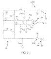
- sensor interface circuit 100 is shown in a first configuration.
- first switch 168 is electrically closed and second switch 170 is electrically open position. This causes current to flow through first input lead 142, first resistor 122, third resistor 132, first output lead 144, and second output lead 146.
- first output lead current leakage path R 144 and second output lead current leakage path R 146 are zero or equivalent to one another, voltage V a(1) and V B(1) will be equivalent, and a differential voltage measurement V Diff(1) reported by differential voltage measurement module 164 will be zero.
- first output lead current leakage path R 144 and second output lead current leakage path R 146 are unequal to one another, voltage V A(1) and V B(1) will be unequal. This will cause differential voltage measurement V Diff(1) reported by differential voltage measurement module 164 to be non-zero. The magnitude of the leakage current will be indicated by the magnitude of differential voltage measurement V Diff(1) . Location of the current leakage, e.g. whether current leakage from one of first output lead 144 and second output lead 146 is greater than the other of the first output lead 144 and second output lead 146, will be indicated by the polarity of differential voltage measurement V Diff(1) .
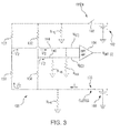
- sensor interface circuit 100 is shown in a second configuration.
- first switch 168 is electrically open and second switch 170 is electrically closed. This causes current to flow through second input lead 148, third resistor 132, fourth resistor 136, first output lead 144, and second output lead 146.
- voltage V A(1) and V B(1) will be equivalent, and a differential voltage measurement V Diff(1) reported by differential voltage measurement module 164 will be zero.
- differential voltage measurement V Diff(2) reported by differential voltage measurement module 164 should be about the same as differential voltage measurement V Diff(1) to be non-zero.
- first input lead current leakage path R 142 and second input lead current leakage path R 148 is non-zero. For example, if there is current leakage through second input lead current leakage path R 148 while first switch 168 is closed and second switch 170 is open, second input lead current leakage path R 148 forms a leg of a voltage divider circuit. This causes differential voltage measurement V Diff(1) to be unequal to V Diff(2) . Similarly, if there is current leakage through first input lead current leakage path R 142 while second switch 170 is closed and first switch 168 is open, first input lead current leakage path R 142 forms a leg of a voltage divider circuit.
- differential voltage measurement V Diff(2) This likewise causes differential voltage measurement V Diff(2) to be unequal to V Diff(1) .
- location and magnitude current leakage from the input leads can be determined by comparing an output of differential voltage measurement module 164 when both first switch 168 and second switch 170 to either differential voltage measurement V Diff(1) and voltage differential measurement V Diff(2) .
- Method 200 includes a step 210 for connecting a first voltage source, e.g. first voltage source 162 (shown in Fig. 1 ) to a first input terminal of the bridge sensor, e.g. first input terminal 112 (shown in Fig. 1 ). Connecting the first voltage source to the first input terminal can include closing the first switch connected between the first voltage source and the first input terminal.
- a first voltage source e.g. first voltage source 162 (shown in Fig. 1 )
- first input terminal of the bridge sensor e.g. first input terminal 112 (shown in Fig. 1 ).
- Connecting the first voltage source to the first input terminal can include closing the first switch connected between the first voltage source and the first input terminal.
- Method 200 also includes a step 220 for determining voltage at a first measurement terminal of a first output lead connected to a first resistive branch of the bridge sensor, e.g. first output lead 144 (shown in Fig. 1 ), and a step 230 for determining voltage at a second measurement terminal of a second output lead connected to a second resistive branch of the bridge sensor, e.g. second output lead 146 (shown in Fig. 1 ).
- Method 200 additionally includes a step 232 for calculating a first differential between the determined voltages, a step 234 for quantifying leakage current flow from one of the first and second output leads using the calculated voltage differential, and a step 236 for determining a location of the leakage current flow from one of the first and second output leads using the first differential voltage.
- method 200 includes a step 240 for connecting a second voltage source, e.g. second voltage source 166 (shown in Fig. 1 ) to a second input terminal, e.g. second input terminal 114 (shown in Fig. 1 ) of the bridge sensor, a step 242 for determining again voltages at the first and second measurement terminals, a step 244 for calculating a second differential between the determined voltages, and a step 246 for quantifying leakage current from an input lead, e.g. second input lead 148 (shown in Fig. 1 ), for connecting the second voltage source to the bridge sensor second input terminal.
- Connecting the second voltage source to the second input terminal can include closing a second switch, e.g.
- method 200 can be iteratively repeated to monitor measurement accuracy over time.
Landscapes
- Physics & Mathematics (AREA)
- General Physics & Mathematics (AREA)
- Testing Of Short-Circuits, Discontinuities, Leakage, Or Incorrect Line Connections (AREA)
- Electronic Switches (AREA)
Abstract
Description
- The present disclosure relates to measurement systems, and more particularly to measurement systems employing bridge circuits.
- A bridge circuit generally includes resistors arranged in two parallel branches between voltage terminals. Each branch generally includes two resistors arranged in series, an intermediate terminal disposed between the resistors, and a 'bridging' branch connecting the intermediate terminals. Typically, one resistor in each parallel branch has a known resistance, a third resistor in one parallel branch has an adjustable variable resistance, and a fourth resistor in the other parallel branch has unknown resistance. By adjusting the variable resistance of the third resistor such that no current flows through the 'bridging' branch the unknown resistance of the fourth resistor can be determined. This is because the ratio of the fixed resistance of the first resistor and the variable resistance of the third resistor is the same as a ratio of the fixed resistance of the second resistor and the unknown resistance of the fourth when no current flows through the 'bridging' branch. By arranging the fourth resistor such that its resistance varies with a parameter of interest, the parameter can be measured by determining the resistance of the fourth resistor.
- One challenge to sensors incorporating such bridge circuits is the influence of unrelated factors on the measured resistance. For example, some bridge circuits can be susceptible to high impedance leakage due to the common mode voltage created at the intermediate terminals. Since the circuit output is not typically a low impedance source, high impedance leakage can cause output changes that can be confused with resistance change due to change in the parameter of interest.
- Such conventional systems and methods have generally been considered satisfactory for their intended purpose. However, there is still a need in the art for improved sensor interface circuits. The present disclosure provides a solution for this need.
- A sensor circuit has a switch that connects to a resistive bridge circuit. The resistive bridge circuit includes a first input terminal, a second input terminal, and a pair of resistive branches that connect between the first and second input terminals. Both the resistive branches include an output terminal. The switch is connected to the first input terminal and is connected electrically in series with the resistive branches for connecting and disconnecting a voltage source from the resistive branch output terminals.
- In certain embodiments, an input lead can be connected between the switch and the first input terminal. A second input lead can be connected between a second switch and the second input terminal. A second voltage source can be connected to the second input terminal through the second switch. It is contemplated that the first and second switches can include mechanical switches, relays, or solid-state devices like transistors.
- In accordance with certain embodiments, the resistive branches can include two resistors electrically connected in series and with the respective output terminal disposed between the resistors. A first output lead can be connected to a first of the output terminals. A second output lead can be connected to a second of the output terminals. The first and second output leads can have measurement terminals disposed on ends opposite the output terminals. A voltage differential measurement module can be connected to the output lead measurement terminals. The voltage differential measurement module can be configured and adapted for acquiring differential voltage measurements at the measurement terminals when either or both of the switches are closed, i.e. when either or both of the voltage sources are connected to the bridge circuit.
- It is contemplated that in certain embodiments a cable can include at least one of the output leads and input leads. The cable can include a current leakage path at a location along a length of the lead. A measurement system can include the first switch, the second switch, and the voltage differential measurement module. The measurement system can be configured and adapted for connecting either or both of the voltage sources to the sensor circuit through the cable, determining differential voltage between the measurement terminals of output leads, and calculating magnitude and/or location of the current leakage path within at least one of the input leads and output leads using the determined differential voltage.
- A method of detecting current leakage within a sensor interface circuit includes connecting a first voltage source to a first input terminal of a bridge sensor, determining voltage at a first measurement terminal of a first output lead connected to a first resistive branch of the bridge sensor, determining voltage at a second measurement terminal of a second output lead connected to a second resistive branch of the bridge sensor, and calculating a first differential between the determined voltages.
- In certain embodiments, method can include quantifying leakage current flow from one of the first and second output leads using the calculated voltage differential. The method can include determining a location of the leakage current flow from one of the first and second output leads using the first differential voltage. Connecting the first voltage source to the first input terminal can include closing a first switch connected between the first voltage source and the first input terminal.
- In accordance with certain embodiments, the method can include connecting a second voltage source to a second input terminal of the bridge sensor, determining again voltages at the first and second measurement terminals, calculating a second differential between the determined voltages, and quantifying leakage current from an input lead connecting the second voltage source to the bridge sensor second input terminal. Connecting the second voltage source to the second input terminal can include closing a second switch connected between the second voltage source and the second input terminal of the bridge sensor. It is also contemplated that the method can include disconnecting the first voltage source and quantifying leakage current from an input lead connected between the first switch and the first input terminal.
- These and other features of the systems and methods of the subject disclosure will become more readily apparent to those skilled in the art from the following detailed description of the preferred embodiments taken in conjunction with the drawings.
- So that those skilled in the art to which the subject disclosure appertains will readily understand how to make and use the systems and methods of the subject disclosure without undue experimentation, preferred embodiments thereof will be described by way of example only and in detail herein below with reference to certain figures, wherein:
-
Fig. 1 is a circuit diagram of a sensor interface circuit constructed in accordance with the present disclosure, showing a bridge sensor, a cable, and a measurement system; -
Fig. 2 is a circuit diagram of the sensor interface circuit ofFig. 1 , showing the circuit in a first configuration wherein a first voltage source is connected to the bridge sensor; -
Fig. 3 is a circuit diagram of the sensor interface circuit ofFig. 1 , showing the circuit in a second configuration wherein a second voltage source is connected to the bridge sensor; and -
Fig. 4 is a method of detecting current leakage attributable to current leakage from leads connected to the bridge sensor ofFig. 1 , showing operations for quantifying and locating current leakages from input and output leads within the cable. - Reference will now be made to the drawings wherein like reference numerals identify similar structural features or aspects of the subject disclosure. For purposes of explanation and illustration, and not limitation, a partial view of an exemplary embodiment of a sensor interface circuit in accordance with the disclosure is shown in
Fig. 1 , and is designated generally byreference character 100. Other embodiments of sensor interface circuits in accordance with the disclosure, or aspects thereof, are provided inFigs. 2 - 4 , as will be described. The systems and methods described herein can be used aerospace and automotive applications detecting current leakage in sensor interface circuits for measuring load, strain, or temperature by way of non-limiting example. - With reference to
Fig. 1 ,sensor interface circuit 100 includes a bridge sensor 110 (shown in dashed outline), a cable 140 (shown in dashed outline), and a measurement system 160 (shown in dashed outline).Cable 140 is connected betweenbridge sensor 110 andmeasurement system 160. It is to be understood thatbridge sensor 110,cable 140, andmeasurement system 160 can be separate assemblies connected together for purposes of acquiring measurements of a parameter of interest. In embodiments,bridge sensor 110 includes precision resistors configured and adapted for measuring the parameter of interest in an aircraft system,cable 140 is a cable assembly such as a wiring harness, andmeasurement system 160 is control circuitry for aircraft electronics configured and adapted acquire measurements of the parameter of interest usingbridge sensor 110. -
Bridge sensor 110 is a resistive bridge sensor having a Wheatstone bridge arrangement.Bridge sensor 110 includes a firstresistive branch 120, a secondresistive branch 130, afirst input terminal 112, and asecond input terminal 114. Firstresistive branch 120 and secondresistive branch 130 are connected betweenfirst input terminal 112 andsecond input terminal 114 such that firstresistive branch 120 and secondresistive branch 130 are electrically in parallel with one another. - First
resistive branch 120 includes afirst resistor 122, afirst output terminal 124, and asecond resistor 126.First resistor 122 is connected betweenfirst input terminal 112 andfirst output terminal 124.Second resistor 126 is connected betweenfirst output terminal 124 andsecond input terminal 114 such thatfirst resistor 122 andsecond resistor 126 are electrically connected in series betweenfirst input terminal 112 andsecond input terminal 114. - Second
resistive branch 130 is similar to firstresistive branch 120 insofar as secondresistive branch 130 includes athird resistor 132, asecond output terminal 134, and afourth resistor 136.Third resistor 132 is connected betweenfirst input terminal 112 andsecond output terminal 134.Fourth resistor 136 is connectedsecond output terminal 134 andsecond input terminal 114 such thatthird resistor 132 andfourth resistor 136 are connected electrically in series with one another betweenfirst input terminal 112 andsecond input terminal 114. At least one of the resistors ofbridge sensor 110, e.g.first resistor 122,second resistor 126,third resistor 132, andfourth resistor 136, is a variable resistor having resistance that is changeable in response to change in a parameter of interest, such load, strain, or temperature by way of non-limiting example. - In embodiments, at least one of
first resistor 122,second resistor 126,third resistor 132, andfourth resistor 136 has variable resistance that varies with a parameter of interest. The remaining resistors have fixed resistance. In certain embodiments, e.g. in pressure sensor circuits, each offirst resistor 122,second resistor 126,third resistor 132, andfourth resistor 136 has variable resistance that varies with a parameter of interest. -
Cable 140 includes four leads coupled betweenbridge sensor 110 andmeasurement system 160.Cable 140 includes afirst input lead 142, asecond input lead 148, afirst output lead 144, and asecond output lead 146 each with opposed sensor and measurement system ends.First input lead 142 is connected tofirst input terminal 112 on its sensor end.Second input lead 148 is connected tosecond input terminal 114 on its sensor end.First output lead 144 is connected tofirst output terminal 124 on its sensor end.Second output lead 146 is connected tosecond output terminal 134 on its sensor end. -
Measurement system 160 includes afirst voltage source 162, a voltagedifferential measurement module 164, and asecond voltage source 166.First voltage source 162 is connected tofirst input terminal 112 throughfirst input lead 142.Second voltage source 166 is connected tosecond input terminal 114 throughsecond input lead 148. Differentialvoltage measurement module 164 is connected tofirst output terminal 124 andsecond output terminal 134 throughfirst output lead 144 andsecond output lead 146, respectively. In embodiments, differentialvoltage measurement module 164 includes a differential amplifier or comparator circuitry configured adapted to output a voltage differential between voltages observed between measurement ends offirst output lead 144 andsecond output lead 146, i.e. at ends oppositefirst output terminal 124 andsecond output terminal 134. Differential voltage measurements can be obtained by (a) acquiring a first single-ended voltage measurement between the end offirst output lead 144 and ground 10, (b) acquiring a second single-ended voltage measurement between the end ofsecond output lead 146 and ground 10, and (c) determining a voltage differential by subtracting the first single-ended measurement from the second single-ended measurement. It is contemplated that the determination is made using software resident on a memory communicative with a processor operatively associated withmeasurement system 160. -
Cable 140 includeselectrical insulation 149. Some cable insulation materials can break down in the presence of substances like water, hydraulic fluid, deicing fluid, or fuel, thereby developing a current leakage path from conductors disposed within the cable. Such current leakage paths can result in stray or spurious signals being emitted by the cable into aircraft structure, potentially reducing reliability. For purposes of illustration,Fig. 1 shows leakages paths from each lead within lead ofcable 140, a first input lead current leakage path R142 extending fromfirst input lead 142 to a ground terminal (illustrated in dashed lines), a second input lead current leakage path R148 extending fromsecond input lead 148 to a ground terminal (illustrated in dashed lines), a first output lead current leakage path R144 extending fromfirst output lead 144 to a ground terminal (illustrated in dashed lines), and a second output lead current leakage path R146 extending fromsecond output lead 146 to a ground potential terminal (illustrated in dashed lines). It is to be appreciated and understood that any or combination of leads withincable 140 can include a current leakage path between the lead and a ground terminal. It is also to be understood that the resistance of such leakage path is on order of many kilo Ohms to several mega Ohms. -
Measurement system 160 also includes afirst switch 168 and asecond switch 170.First switch 168 is connected between afirst voltage source 162 andfirst input lead 142 and is configured and adapted for electrically connecting and disconnectingfirst voltage source 162 fromfirst input terminal 112.Second switch 170 is connected between asecond voltage source 166 andsecond input lead 148 and is configured and adapted for electrically connecting and disconnectingsecond voltage source 166 fromsecond input terminal 114.First switch 168 andsecond switch 170 can be mechanical switches or relays. In certain embodiments,first switch 168 andsecond switch 170 are solid-state devices such as MOSFETs or IGBTs that are operatively associated with a controller communicative with a memory having instructions recorded thereon to electrically open and close the switches in accordance with the below-described method. - With reference to
Fig. 2 ,sensor interface circuit 100 is shown in a first configuration. In the first configuration,first switch 168 is electrically closed andsecond switch 170 is electrically open position. This causes current to flow throughfirst input lead 142,first resistor 122,third resistor 132,first output lead 144, andsecond output lead 146. When first output lead current leakage path R144 and second output lead current leakage path R146 are zero or equivalent to one another, voltage Va(1) and VB(1) will be equivalent, and a differential voltage measurement VDiff(1) reported by differentialvoltage measurement module 164 will be zero. - In the event that first output lead current leakage path R144 and second output lead current leakage path R146 are unequal to one another, voltage VA(1) and VB(1) will be unequal. This will cause differential voltage measurement VDiff(1) reported by differential
voltage measurement module 164 to be non-zero. The magnitude of the leakage current will be indicated by the magnitude of differential voltage measurement VDiff(1). Location of the current leakage, e.g. whether current leakage from one offirst output lead 144 andsecond output lead 146 is greater than the other of thefirst output lead 144 andsecond output lead 146, will be indicated by the polarity of differential voltage measurement VDiff(1). - With reference to
Fig. 3 ,sensor interface circuit 100 is shown in a second configuration. In the second configuration,first switch 168 is electrically open andsecond switch 170 is electrically closed. This causes current to flow throughsecond input lead 148,third resistor 132,fourth resistor 136,first output lead 144, andsecond output lead 146. As with the first configuration, when first output lead current leakage path R144 and second output lead current leakage path R146 are zero or equivalent to one another, voltage VA(1) and VB(1) will be equivalent, and a differential voltage measurement VDiff(1) reported by differentialvoltage measurement module 164 will be zero. Similarly, if that first output lead current leakage path R144 and second output lead current leakage path R146 are unequal to one another, voltage VA(1) and VB(1) should be unequal. Specifically, differential voltage measurement VDiff(2) reported by differentialvoltage measurement module 164 should be about the same as differential voltage measurement VDiff(1) to be non-zero. - In the event that differential voltage measurement VDiff(2) is not equivalent to voltage differential measurement VDiff(1), then at least one of first input lead current leakage path R142 and second input lead current leakage path R148 is non-zero. For example, if there is current leakage through second input lead current leakage path R148 while
first switch 168 is closed andsecond switch 170 is open, second input lead current leakage path R148 forms a leg of a voltage divider circuit. This causes differential voltage measurement VDiff(1) to be unequal to VDiff(2). Similarly, if there is current leakage through first input lead current leakage path R142 whilesecond switch 170 is closed andfirst switch 168 is open, first input lead current leakage path R142 forms a leg of a voltage divider circuit. This likewise causes differential voltage measurement VDiff(2) to be unequal to VDiff(1). Under these circumstances, location and magnitude current leakage from the input leads can be determined by comparing an output of differentialvoltage measurement module 164 when bothfirst switch 168 andsecond switch 170 to either differential voltage measurement VDiff(1) and voltage differential measurement VDiff(2). - With reference to
Fig. 4 , amethod 200 of detecting current leakage within a sensor interface circuit, e.g. bridge sensor 110 (shown inFig. 1 ), is shown.Method 200 includes astep 210 for connecting a first voltage source, e.g. first voltage source 162 (shown inFig. 1 ) to a first input terminal of the bridge sensor, e.g. first input terminal 112 (shown inFig. 1 ). Connecting the first voltage source to the first input terminal can include closing the first switch connected between the first voltage source and the first input terminal. -
Method 200 also includes astep 220 for determining voltage at a first measurement terminal of a first output lead connected to a first resistive branch of the bridge sensor, e.g. first output lead 144 (shown inFig. 1 ), and astep 230 for determining voltage at a second measurement terminal of a second output lead connected to a second resistive branch of the bridge sensor, e.g. second output lead 146 (shown inFig. 1 ).Method 200 additionally includes a step 232 for calculating a first differential between the determined voltages, a step 234 for quantifying leakage current flow from one of the first and second output leads using the calculated voltage differential, and a step 236 for determining a location of the leakage current flow from one of the first and second output leads using the first differential voltage. - In embodiments,
method 200 includes astep 240 for connecting a second voltage source, e.g. second voltage source 166 (shown inFig. 1 ) to a second input terminal, e.g. second input terminal 114 (shown inFig. 1 ) of the bridge sensor, a step 242 for determining again voltages at the first and second measurement terminals, a step 244 for calculating a second differential between the determined voltages, and a step 246 for quantifying leakage current from an input lead, e.g. second input lead 148 (shown inFig. 1 ), for connecting the second voltage source to the bridge sensor second input terminal. Connecting the second voltage source to the second input terminal can include closing a second switch, e.g. second switch 170 (shown inFig. 1 ), connected between the second voltage source and the second input terminal of the bridge sensor. It is also contemplated that the method can include a step 248 for disconnecting the first voltage source and astep 250 for quantifying leakage current from an input lead connected between the first switch and the first input terminal. As indicated byreference numeral 270,method 200 can be iteratively repeated to monitor measurement accuracy over time. - Conventional bridge-type sensors can be susceptible to high impedance leakage due to the common mode voltage created at the sensor outputs. As the sensor output is not typically a low impedance source, this can cause error in measurements acquired using the sensor as the sensor output can be degraded by the unintended leakage path. Embodiments of sensor interface circuits described herein allow evaluating differential leakage between the sensor outputs. Determining differential leakage between the sensor outputs allows for determining relative magnitude of the leakages. Once determined, sensor output can be adjusted in view of the relative magnitudes of the leakages, thereby compensating for potentially degraded measurement system performance and avoiding measurement inaccuracy.
- The methods and systems of the present disclosure, as described above and shown in the drawings, provide for bridge sensor interface circuits with superior properties including increased accuracy. While the apparatus and methods of the subject disclosure have been shown and described with reference to preferred embodiments, those skilled in the art will readily appreciate that changes and/or modifications may be made thereto without departing from the scope of the subject disclosure.
Claims (15)
- A sensor interface circuit (100), comprising:first and second input terminals (112, 114);a resistive bridge circuit (110) including a pair of parallel resistive branches (120, 130) connected between the first and second input terminals (112, 114), both resistive branches (120, 130) including an output terminal (124, 134) disposed between serially arranged resistors (122, 132) of the resistive branches; anda switch (168) connected to the first input terminal (112) and in series with the resistive branches (120, 130) for connecting a voltage source (162) to both resistive branch output terminals.
- A circuit (100) as recited in claim 1, further including a voltage source (162) connected to the first input terminal through the switch (168).
- A circuit (100) as recited in claim 2, wherein the voltage source is a first voltage source (162) and further including a second voltage source (166) connected to the second input terminal (114).
- A circuit (100) as recited in claim 1, wherein the switch is a first switch (168) and further including a second switch (170) connected to the second input terminal (114).
- A circuit (100) as recited in claim 4, wherein the second switch (170) is connected in series with both of the parallel resistive branches (120, 130).
- A circuit (100) as recited in claim 1, further including a voltage differential measurement module (164) connected to the resistive branch output terminals.
- A circuit (100) as recited in claim 6, further including an output lead (144) connected between an output of the first resistive branch (120) and the voltage differential measurement module (164).
- A circuit (100) as recited in claim 7, further including an input lead connecting the switch to the voltage differential measurement module through the output lead.
- A method of detecting current leakage within a sensor interface circuit (100), comprising:connecting a first voltage source (162) to a first input terminal (112) of a bridge sensor (110);determining voltage at a first measurement terminal of a first output lead (144) connected to a first resistive branch (120) of the bridge sensor (110);determining voltage at a second measurement terminal of a second output lead (146) connected to a second resistive branch (130) of the bridge sensor (110); andcalculating a first differential between the determined voltages.
- A method as recited in claim 9, further including quantifying leakage current flow from one of the first and second output leads (144, 146) using the calculated voltage differential.
- A method as recited in claim 9, further including determining a location of the leakage current flow from one of the first and second output leads (144, 146) using the first differential.
- A method as recited in claim 9, wherein connecting the first voltage source (162) to the first input terminal (112) includes closing a first switch (168) connected between the first voltage source (162) and the first input terminal (112) of the bridge sensor (110).
- A method as recited in claim 9, further including:connecting a second voltage source (166) to a second input terminal (114) of the bridge sensor (110);determining voltage at the first measurement terminal;determining voltage at the second measurement terminal;calculating a second differential between the determined voltages;quantifying leakage current from an input lead connecting the second voltage source (166) to the bridge sensor second input terminal (114).
- A method as recited in claim 13, wherein connecting the second voltage source (166) to the second input terminal includes closing a second switch (170) connected between the second voltage source (166) and the second input terminal (114) of the bridge sensor (110).
- A method as recited in claim 13, further including:disconnecting the first voltage source (162); andquantifying leakage current from an input lead connected between the first switch (168) and the first input terminal (112).
Applications Claiming Priority (1)
| Application Number | Priority Date | Filing Date | Title |
|---|---|---|---|
| US14/457,954 US9726705B2 (en) | 2014-08-12 | 2014-08-12 | Sensor interface circuits |
Publications (2)
| Publication Number | Publication Date |
|---|---|
| EP2988136A1 true EP2988136A1 (en) | 2016-02-24 |
| EP2988136B1 EP2988136B1 (en) | 2020-04-15 |
Family
ID=53871879
Family Applications (1)
| Application Number | Title | Priority Date | Filing Date |
|---|---|---|---|
| EP15179981.4A Active EP2988136B1 (en) | 2014-08-12 | 2015-08-06 | Sensor interface circuits |
Country Status (4)
| Country | Link |
|---|---|
| US (1) | US9726705B2 (en) |
| EP (1) | EP2988136B1 (en) |
| BR (1) | BR102015019233B1 (en) |
| CA (1) | CA2898377C (en) |
Cited By (1)
| Publication number | Priority date | Publication date | Assignee | Title |
|---|---|---|---|---|
| IT201600077188A1 (en) * | 2016-07-22 | 2018-01-22 | St Microelectronics Srl | PROCEDURE FOR COMPENSATING SUBSTRATE STRESS EFFECTS IN SEMICONDUCTOR AND CORRESPONDING DEVICES |
Families Citing this family (9)
| Publication number | Priority date | Publication date | Assignee | Title |
|---|---|---|---|---|
| US20140241400A1 (en) * | 2013-02-27 | 2014-08-28 | Linear Technology Corporation | Rotating 3-wire resistance temperature detection excitation current sources and method |
| JP6092129B2 (en) * | 2014-01-16 | 2017-03-08 | アズビル株式会社 | Temperature measuring system and temperature measuring instrument |
| DE102016111984B4 (en) * | 2016-06-30 | 2021-12-23 | Infineon Technologies Ag | Magnetic sensor components and method for determining a direction of rotation of a magnetic component about an axis of rotation |
| US10101175B2 (en) | 2016-11-15 | 2018-10-16 | Industrial Technology Research Institute | Sensor interface circuit and sensor output adjusting method |
| US10126347B2 (en) * | 2016-12-29 | 2018-11-13 | Infineon Technologies Ag | Passive bridge circuit with oxide windows as leakage sink |
| JP6603695B2 (en) * | 2017-09-15 | 2019-11-06 | 矢崎総業株式会社 | Anomaly detection device |
| EP3581906B1 (en) * | 2018-06-13 | 2020-12-02 | Infineon Technologies AG | Sensor |
| CN111044768B (en) * | 2018-10-15 | 2022-05-31 | 大陆汽车有限责任公司 | Method for operating a current sensor and current sensor |
| US20230099576A1 (en) * | 2021-09-30 | 2023-03-30 | Baker Hughes Holdings Llc | Universal interface |
Citations (4)
| Publication number | Priority date | Publication date | Assignee | Title |
|---|---|---|---|---|
| US3960010A (en) * | 1973-10-23 | 1976-06-01 | Ab Bofors | Analog-digital converter for a resistance bridge |
| GB2165647A (en) * | 1984-08-07 | 1986-04-16 | Hanson Res | Method of conducting measurement using an electro-mechanical transducer |
| GB2196131A (en) * | 1986-10-03 | 1988-04-20 | Endress Hauser Gmbh Co | Arrangement for processing the output signals of a resistance bridge |
| WO2014094777A1 (en) * | 2012-12-17 | 2014-06-26 | Danfoss A/S | A sensor comprising a substrate |
Family Cites Families (1)
| Publication number | Priority date | Publication date | Assignee | Title |
|---|---|---|---|---|
| DE102006051365B4 (en) * | 2006-10-27 | 2011-04-21 | Sartorius Ag | Measuring amplification device and method |
-
2014
- 2014-08-12 US US14/457,954 patent/US9726705B2/en active Active
-
2015
- 2015-07-23 CA CA2898377A patent/CA2898377C/en active Active
- 2015-08-06 EP EP15179981.4A patent/EP2988136B1/en active Active
- 2015-08-11 BR BR102015019233-9A patent/BR102015019233B1/en active IP Right Grant
Patent Citations (4)
| Publication number | Priority date | Publication date | Assignee | Title |
|---|---|---|---|---|
| US3960010A (en) * | 1973-10-23 | 1976-06-01 | Ab Bofors | Analog-digital converter for a resistance bridge |
| GB2165647A (en) * | 1984-08-07 | 1986-04-16 | Hanson Res | Method of conducting measurement using an electro-mechanical transducer |
| GB2196131A (en) * | 1986-10-03 | 1988-04-20 | Endress Hauser Gmbh Co | Arrangement for processing the output signals of a resistance bridge |
| WO2014094777A1 (en) * | 2012-12-17 | 2014-06-26 | Danfoss A/S | A sensor comprising a substrate |
Cited By (2)
| Publication number | Priority date | Publication date | Assignee | Title |
|---|---|---|---|---|
| IT201600077188A1 (en) * | 2016-07-22 | 2018-01-22 | St Microelectronics Srl | PROCEDURE FOR COMPENSATING SUBSTRATE STRESS EFFECTS IN SEMICONDUCTOR AND CORRESPONDING DEVICES |
| US10250233B2 (en) | 2016-07-22 | 2019-04-02 | Stmicroelectronics S.R.L. | Method for compensating effects of substrate stresses in semiconductor devices, and corresponding device |
Also Published As
| Publication number | Publication date |
|---|---|
| CA2898377A1 (en) | 2016-02-12 |
| BR102015019233A2 (en) | 2016-02-16 |
| US9726705B2 (en) | 2017-08-08 |
| US20160047852A1 (en) | 2016-02-18 |
| EP2988136B1 (en) | 2020-04-15 |
| CA2898377C (en) | 2022-08-23 |
| BR102015019233B1 (en) | 2022-10-11 |
Similar Documents
| Publication | Publication Date | Title |
|---|---|---|
| US9726705B2 (en) | Sensor interface circuits | |
| JP5667192B2 (en) | Multiplexer for detecting and correcting leakage current | |
| US11280844B2 (en) | Device and method for monitoring a reliability of a cell impedance measurement of a battery cell | |
| CN107257915B (en) | Measuring bridge assembly and method with improved fault detection | |
| US8508217B2 (en) | Output circuit of charge mode sensor | |
| EP3022737B1 (en) | Current sense circuit with offset calibration | |
| CN101283282B (en) | Current measurement circuit and method of diagnosing a fault in a current measurement circuit | |
| US5416470A (en) | Contact judging circuit and contact judging method for impedance measuring apparatus | |
| CN102472646A (en) | Excitation circuit for DC sensors | |
| GB2507092A (en) | Method and circuit for measuring the electrical insulation resistance of a thermocouple | |
| EP2833157A1 (en) | Identifying defective electrical cables | |
| CN108508316A (en) | Short-circuit positioning device | |
| GB2507093A (en) | Method and circuit for measuring the electrical resistance of a thermocouple | |
| US11143560B2 (en) | Electronic circuit for driving a thermocouple element, temperature sensing device, and method for observing a leakage resistance of the thermocouple element | |
| US10634565B2 (en) | Temperature sensing apparatus and temperature sensing method thereof | |
| EP3467524B1 (en) | Sensor interfaces, sensor arrangements, and open circuit detection methods for sensor interfaces and arrangements | |
| US12392836B2 (en) | Battery sensor | |
| CN109564139A (en) | Sensor device | |
| EP3130894B1 (en) | Abnormality detection device for sensor and sensor device | |
| RU178894U1 (en) | SMALL RESISTANCE METER | |
| EP3719463B1 (en) | Highly failure tolerant temperature acquisition for thermocouple applications | |
| US20230099576A1 (en) | Universal interface | |
| US20140241400A1 (en) | Rotating 3-wire resistance temperature detection excitation current sources and method | |
| EP2921832B1 (en) | 3-wire resistance temperature detector and method of measuring said resistance | |
| RU2405131C1 (en) | Temperature difference metre with thermistor transducers |
Legal Events
| Date | Code | Title | Description |
|---|---|---|---|
| PUAI | Public reference made under article 153(3) epc to a published international application that has entered the european phase |
Free format text: ORIGINAL CODE: 0009012 |
|
| AK | Designated contracting states |
Kind code of ref document: A1 Designated state(s): AL AT BE BG CH CY CZ DE DK EE ES FI FR GB GR HR HU IE IS IT LI LT LU LV MC MK MT NL NO PL PT RO RS SE SI SK SM TR |
|
| AX | Request for extension of the european patent |
Extension state: BA ME |
|
| 17P | Request for examination filed |
Effective date: 20160824 |
|
| RBV | Designated contracting states (corrected) |
Designated state(s): AL AT BE BG CH CY CZ DE DK EE ES FI FR GB GR HR HU IE IS IT LI LT LU LV MC MK MT NL NO PL PT RO RS SE SI SK SM TR |
|
| STAA | Information on the status of an ep patent application or granted ep patent |
Free format text: STATUS: EXAMINATION IS IN PROGRESS |
|
| 17Q | First examination report despatched |
Effective date: 20181019 |
|
| GRAP | Despatch of communication of intention to grant a patent |
Free format text: ORIGINAL CODE: EPIDOSNIGR1 |
|
| STAA | Information on the status of an ep patent application or granted ep patent |
Free format text: STATUS: GRANT OF PATENT IS INTENDED |
|
| INTG | Intention to grant announced |
Effective date: 20191105 |
|
| GRAS | Grant fee paid |
Free format text: ORIGINAL CODE: EPIDOSNIGR3 |
|
| GRAA | (expected) grant |
Free format text: ORIGINAL CODE: 0009210 |
|
| STAA | Information on the status of an ep patent application or granted ep patent |
Free format text: STATUS: THE PATENT HAS BEEN GRANTED |
|
| AK | Designated contracting states |
Kind code of ref document: B1 Designated state(s): AL AT BE BG CH CY CZ DE DK EE ES FI FR GB GR HR HU IE IS IT LI LT LU LV MC MK MT NL NO PL PT RO RS SE SI SK SM TR |
|
| REG | Reference to a national code |
Ref country code: CH Ref legal event code: EP |
|
| REG | Reference to a national code |
Ref country code: DE Ref legal event code: R096 Ref document number: 602015050619 Country of ref document: DE |
|
| REG | Reference to a national code |
Ref country code: IE Ref legal event code: FG4D |
|
| REG | Reference to a national code |
Ref country code: AT Ref legal event code: REF Ref document number: 1257945 Country of ref document: AT Kind code of ref document: T Effective date: 20200515 |
|
| REG | Reference to a national code |
Ref country code: NL Ref legal event code: MP Effective date: 20200415 |
|
| REG | Reference to a national code |
Ref country code: LT Ref legal event code: MG4D |
|
| PG25 | Lapsed in a contracting state [announced via postgrant information from national office to epo] |
Ref country code: GR Free format text: LAPSE BECAUSE OF FAILURE TO SUBMIT A TRANSLATION OF THE DESCRIPTION OR TO PAY THE FEE WITHIN THE PRESCRIBED TIME-LIMIT Effective date: 20200716 Ref country code: PT Free format text: LAPSE BECAUSE OF FAILURE TO SUBMIT A TRANSLATION OF THE DESCRIPTION OR TO PAY THE FEE WITHIN THE PRESCRIBED TIME-LIMIT Effective date: 20200817 Ref country code: NO Free format text: LAPSE BECAUSE OF FAILURE TO SUBMIT A TRANSLATION OF THE DESCRIPTION OR TO PAY THE FEE WITHIN THE PRESCRIBED TIME-LIMIT Effective date: 20200715 Ref country code: SE Free format text: LAPSE BECAUSE OF FAILURE TO SUBMIT A TRANSLATION OF THE DESCRIPTION OR TO PAY THE FEE WITHIN THE PRESCRIBED TIME-LIMIT Effective date: 20200415 Ref country code: FI Free format text: LAPSE BECAUSE OF FAILURE TO SUBMIT A TRANSLATION OF THE DESCRIPTION OR TO PAY THE FEE WITHIN THE PRESCRIBED TIME-LIMIT Effective date: 20200415 Ref country code: IS Free format text: LAPSE BECAUSE OF FAILURE TO SUBMIT A TRANSLATION OF THE DESCRIPTION OR TO PAY THE FEE WITHIN THE PRESCRIBED TIME-LIMIT Effective date: 20200815 Ref country code: NL Free format text: LAPSE BECAUSE OF FAILURE TO SUBMIT A TRANSLATION OF THE DESCRIPTION OR TO PAY THE FEE WITHIN THE PRESCRIBED TIME-LIMIT Effective date: 20200415 Ref country code: LT Free format text: LAPSE BECAUSE OF FAILURE TO SUBMIT A TRANSLATION OF THE DESCRIPTION OR TO PAY THE FEE WITHIN THE PRESCRIBED TIME-LIMIT Effective date: 20200415 |
|
| REG | Reference to a national code |
Ref country code: AT Ref legal event code: MK05 Ref document number: 1257945 Country of ref document: AT Kind code of ref document: T Effective date: 20200415 |
|
| PG25 | Lapsed in a contracting state [announced via postgrant information from national office to epo] |
Ref country code: HR Free format text: LAPSE BECAUSE OF FAILURE TO SUBMIT A TRANSLATION OF THE DESCRIPTION OR TO PAY THE FEE WITHIN THE PRESCRIBED TIME-LIMIT Effective date: 20200415 Ref country code: LV Free format text: LAPSE BECAUSE OF FAILURE TO SUBMIT A TRANSLATION OF THE DESCRIPTION OR TO PAY THE FEE WITHIN THE PRESCRIBED TIME-LIMIT Effective date: 20200415 Ref country code: BG Free format text: LAPSE BECAUSE OF FAILURE TO SUBMIT A TRANSLATION OF THE DESCRIPTION OR TO PAY THE FEE WITHIN THE PRESCRIBED TIME-LIMIT Effective date: 20200715 Ref country code: RS Free format text: LAPSE BECAUSE OF FAILURE TO SUBMIT A TRANSLATION OF THE DESCRIPTION OR TO PAY THE FEE WITHIN THE PRESCRIBED TIME-LIMIT Effective date: 20200415 |
|
| PG25 | Lapsed in a contracting state [announced via postgrant information from national office to epo] |
Ref country code: AL Free format text: LAPSE BECAUSE OF FAILURE TO SUBMIT A TRANSLATION OF THE DESCRIPTION OR TO PAY THE FEE WITHIN THE PRESCRIBED TIME-LIMIT Effective date: 20200415 |
|
| REG | Reference to a national code |
Ref country code: DE Ref legal event code: R097 Ref document number: 602015050619 Country of ref document: DE |
|
| PG25 | Lapsed in a contracting state [announced via postgrant information from national office to epo] |
Ref country code: ES Free format text: LAPSE BECAUSE OF FAILURE TO SUBMIT A TRANSLATION OF THE DESCRIPTION OR TO PAY THE FEE WITHIN THE PRESCRIBED TIME-LIMIT Effective date: 20200415 Ref country code: CZ Free format text: LAPSE BECAUSE OF FAILURE TO SUBMIT A TRANSLATION OF THE DESCRIPTION OR TO PAY THE FEE WITHIN THE PRESCRIBED TIME-LIMIT Effective date: 20200415 Ref country code: AT Free format text: LAPSE BECAUSE OF FAILURE TO SUBMIT A TRANSLATION OF THE DESCRIPTION OR TO PAY THE FEE WITHIN THE PRESCRIBED TIME-LIMIT Effective date: 20200415 Ref country code: DK Free format text: LAPSE BECAUSE OF FAILURE TO SUBMIT A TRANSLATION OF THE DESCRIPTION OR TO PAY THE FEE WITHIN THE PRESCRIBED TIME-LIMIT Effective date: 20200415 Ref country code: EE Free format text: LAPSE BECAUSE OF FAILURE TO SUBMIT A TRANSLATION OF THE DESCRIPTION OR TO PAY THE FEE WITHIN THE PRESCRIBED TIME-LIMIT Effective date: 20200415 Ref country code: IT Free format text: LAPSE BECAUSE OF FAILURE TO SUBMIT A TRANSLATION OF THE DESCRIPTION OR TO PAY THE FEE WITHIN THE PRESCRIBED TIME-LIMIT Effective date: 20200415 Ref country code: SM Free format text: LAPSE BECAUSE OF FAILURE TO SUBMIT A TRANSLATION OF THE DESCRIPTION OR TO PAY THE FEE WITHIN THE PRESCRIBED TIME-LIMIT Effective date: 20200415 Ref country code: RO Free format text: LAPSE BECAUSE OF FAILURE TO SUBMIT A TRANSLATION OF THE DESCRIPTION OR TO PAY THE FEE WITHIN THE PRESCRIBED TIME-LIMIT Effective date: 20200415 |
|
| PLBE | No opposition filed within time limit |
Free format text: ORIGINAL CODE: 0009261 |
|
| STAA | Information on the status of an ep patent application or granted ep patent |
Free format text: STATUS: NO OPPOSITION FILED WITHIN TIME LIMIT |
|
| PG25 | Lapsed in a contracting state [announced via postgrant information from national office to epo] |
Ref country code: SK Free format text: LAPSE BECAUSE OF FAILURE TO SUBMIT A TRANSLATION OF THE DESCRIPTION OR TO PAY THE FEE WITHIN THE PRESCRIBED TIME-LIMIT Effective date: 20200415 Ref country code: PL Free format text: LAPSE BECAUSE OF FAILURE TO SUBMIT A TRANSLATION OF THE DESCRIPTION OR TO PAY THE FEE WITHIN THE PRESCRIBED TIME-LIMIT Effective date: 20200415 |
|
| 26N | No opposition filed |
Effective date: 20210118 |
|
| PG25 | Lapsed in a contracting state [announced via postgrant information from national office to epo] |
Ref country code: MC Free format text: LAPSE BECAUSE OF FAILURE TO SUBMIT A TRANSLATION OF THE DESCRIPTION OR TO PAY THE FEE WITHIN THE PRESCRIBED TIME-LIMIT Effective date: 20200415 |
|
| REG | Reference to a national code |
Ref country code: CH Ref legal event code: PL |
|
| PG25 | Lapsed in a contracting state [announced via postgrant information from national office to epo] |
Ref country code: LI Free format text: LAPSE BECAUSE OF NON-PAYMENT OF DUE FEES Effective date: 20200831 Ref country code: LU Free format text: LAPSE BECAUSE OF NON-PAYMENT OF DUE FEES Effective date: 20200806 Ref country code: CH Free format text: LAPSE BECAUSE OF NON-PAYMENT OF DUE FEES Effective date: 20200831 |
|
| REG | Reference to a national code |
Ref country code: BE Ref legal event code: MM Effective date: 20200831 |
|
| PG25 | Lapsed in a contracting state [announced via postgrant information from national office to epo] |
Ref country code: SI Free format text: LAPSE BECAUSE OF FAILURE TO SUBMIT A TRANSLATION OF THE DESCRIPTION OR TO PAY THE FEE WITHIN THE PRESCRIBED TIME-LIMIT Effective date: 20200415 |
|
| PG25 | Lapsed in a contracting state [announced via postgrant information from national office to epo] |
Ref country code: BE Free format text: LAPSE BECAUSE OF NON-PAYMENT OF DUE FEES Effective date: 20200831 Ref country code: IE Free format text: LAPSE BECAUSE OF NON-PAYMENT OF DUE FEES Effective date: 20200806 |
|
| PG25 | Lapsed in a contracting state [announced via postgrant information from national office to epo] |
Ref country code: TR Free format text: LAPSE BECAUSE OF FAILURE TO SUBMIT A TRANSLATION OF THE DESCRIPTION OR TO PAY THE FEE WITHIN THE PRESCRIBED TIME-LIMIT Effective date: 20200415 Ref country code: MT Free format text: LAPSE BECAUSE OF FAILURE TO SUBMIT A TRANSLATION OF THE DESCRIPTION OR TO PAY THE FEE WITHIN THE PRESCRIBED TIME-LIMIT Effective date: 20200415 Ref country code: CY Free format text: LAPSE BECAUSE OF FAILURE TO SUBMIT A TRANSLATION OF THE DESCRIPTION OR TO PAY THE FEE WITHIN THE PRESCRIBED TIME-LIMIT Effective date: 20200415 |
|
| PG25 | Lapsed in a contracting state [announced via postgrant information from national office to epo] |
Ref country code: MK Free format text: LAPSE BECAUSE OF FAILURE TO SUBMIT A TRANSLATION OF THE DESCRIPTION OR TO PAY THE FEE WITHIN THE PRESCRIBED TIME-LIMIT Effective date: 20200415 |
|
| PGFP | Annual fee paid to national office [announced via postgrant information from national office to epo] |
Ref country code: DE Payment date: 20250724 Year of fee payment: 11 |
|
| PGFP | Annual fee paid to national office [announced via postgrant information from national office to epo] |
Ref country code: GB Payment date: 20250724 Year of fee payment: 11 |
|
| PGFP | Annual fee paid to national office [announced via postgrant information from national office to epo] |
Ref country code: FR Payment date: 20250725 Year of fee payment: 11 |
|
| REG | Reference to a national code |
Ref country code: GB Ref legal event code: 732E Free format text: REGISTERED BETWEEN 20251120 AND 20251126 |
|
| P01 | Opt-out of the competence of the unified patent court (upc) registered |
Free format text: CASE NUMBER: UPC_APP_0016967_2988136/2025 Effective date: 20251210 |
|
| REG | Reference to a national code |
Ref country code: DE Ref legal event code: R081 Ref document number: 602015050619 Country of ref document: DE Owner name: GOODRICH CORPORATION, CHARLOTTE, US Free format text: FORMER OWNERS: HAMILTON SUNDSTRAND CORPORATION, CHARLOTTE, N.C., US; SIMMONDS PRECISION PRODUCTS, INC., VERGENNES, VT., US Ref country code: DE Ref legal event code: R081 Ref document number: 602015050619 Country of ref document: DE Owner name: HAMILTON SUNDSTRAND CORPORATION, CHARLOTTE, US Free format text: FORMER OWNERS: HAMILTON SUNDSTRAND CORPORATION, CHARLOTTE, N.C., US; SIMMONDS PRECISION PRODUCTS, INC., VERGENNES, VT., US |