EP2988070B1 - Floor-integrated system - Google Patents
Floor-integrated system Download PDFInfo
- Publication number
- EP2988070B1 EP2988070B1 EP13885755.2A EP13885755A EP2988070B1 EP 2988070 B1 EP2988070 B1 EP 2988070B1 EP 13885755 A EP13885755 A EP 13885755A EP 2988070 B1 EP2988070 B1 EP 2988070B1
- Authority
- EP
- European Patent Office
- Prior art keywords
- positioning
- floor
- integrated system
- heat conducting
- heat
- Prior art date
- Legal status (The legal status is an assumption and is not a legal conclusion. Google has not performed a legal analysis and makes no representation as to the accuracy of the status listed.)
- Active
Links
Images


Classifications
-
- E—FIXED CONSTRUCTIONS
- E04—BUILDING
- E04C—STRUCTURAL ELEMENTS; BUILDING MATERIALS
- E04C2/00—Building elements of relatively thin form for the construction of parts of buildings, e.g. sheet materials, slabs, or panels
- E04C2/44—Building elements of relatively thin form for the construction of parts of buildings, e.g. sheet materials, slabs, or panels characterised by the purpose
- E04C2/52—Building elements of relatively thin form for the construction of parts of buildings, e.g. sheet materials, slabs, or panels characterised by the purpose with special adaptations for auxiliary purposes, e.g. serving for locating conduits
- E04C2/521—Building elements of relatively thin form for the construction of parts of buildings, e.g. sheet materials, slabs, or panels characterised by the purpose with special adaptations for auxiliary purposes, e.g. serving for locating conduits serving for locating conduits; for ventilating, heating or cooling
- E04C2/525—Building elements of relatively thin form for the construction of parts of buildings, e.g. sheet materials, slabs, or panels characterised by the purpose with special adaptations for auxiliary purposes, e.g. serving for locating conduits serving for locating conduits; for ventilating, heating or cooling for heating or cooling
-
- E—FIXED CONSTRUCTIONS
- E04—BUILDING
- E04F—FINISHING WORK ON BUILDINGS, e.g. STAIRS, FLOORS
- E04F15/00—Flooring
- E04F15/02—Flooring or floor layers composed of a number of similar elements
-
- E—FIXED CONSTRUCTIONS
- E04—BUILDING
- E04F—FINISHING WORK ON BUILDINGS, e.g. STAIRS, FLOORS
- E04F15/00—Flooring
- E04F15/02—Flooring or floor layers composed of a number of similar elements
- E04F15/08—Flooring or floor layers composed of a number of similar elements only of stone or stone-like material, e.g. ceramics, concrete; of glass or with a top layer of stone or stone-like material, e.g. ceramics, concrete or glass
-
- E—FIXED CONSTRUCTIONS
- E04—BUILDING
- E04F—FINISHING WORK ON BUILDINGS, e.g. STAIRS, FLOORS
- E04F15/00—Flooring
- E04F15/18—Separately-laid insulating layers; Other additional insulating measures; Floating floors
- E04F15/185—Underlayers in the form of studded or ribbed plates
-
- F—MECHANICAL ENGINEERING; LIGHTING; HEATING; WEAPONS; BLASTING
- F24—HEATING; RANGES; VENTILATING
- F24D—DOMESTIC- OR SPACE-HEATING SYSTEMS, e.g. CENTRAL HEATING SYSTEMS; DOMESTIC HOT-WATER SUPPLY SYSTEMS; ELEMENTS OR COMPONENTS THEREFOR
- F24D13/00—Electric heating systems
- F24D13/02—Electric heating systems solely using resistance heating, e.g. underfloor heating
- F24D13/022—Electric heating systems solely using resistance heating, e.g. underfloor heating resistances incorporated in construction elements
-
- F—MECHANICAL ENGINEERING; LIGHTING; HEATING; WEAPONS; BLASTING
- F24—HEATING; RANGES; VENTILATING
- F24D—DOMESTIC- OR SPACE-HEATING SYSTEMS, e.g. CENTRAL HEATING SYSTEMS; DOMESTIC HOT-WATER SUPPLY SYSTEMS; ELEMENTS OR COMPONENTS THEREFOR
- F24D3/00—Hot-water central heating systems
- F24D3/12—Tube and panel arrangements for ceiling, wall, or underfloor heating
- F24D3/14—Tube and panel arrangements for ceiling, wall, or underfloor heating incorporated in a ceiling, wall or floor
-
- F—MECHANICAL ENGINEERING; LIGHTING; HEATING; WEAPONS; BLASTING
- F24—HEATING; RANGES; VENTILATING
- F24D—DOMESTIC- OR SPACE-HEATING SYSTEMS, e.g. CENTRAL HEATING SYSTEMS; DOMESTIC HOT-WATER SUPPLY SYSTEMS; ELEMENTS OR COMPONENTS THEREFOR
- F24D3/00—Hot-water central heating systems
- F24D3/12—Tube and panel arrangements for ceiling, wall, or underfloor heating
- F24D3/14—Tube and panel arrangements for ceiling, wall, or underfloor heating incorporated in a ceiling, wall or floor
- F24D3/141—Tube mountings specially adapted therefor
- F24D3/142—Tube mountings specially adapted therefor integrated in prefab construction elements
-
- E—FIXED CONSTRUCTIONS
- E04—BUILDING
- E04F—FINISHING WORK ON BUILDINGS, e.g. STAIRS, FLOORS
- E04F15/00—Flooring
- E04F15/02—Flooring or floor layers composed of a number of similar elements
- E04F15/02044—Separate elements for fastening to an underlayer
- E04F2015/02105—Separate elements for fastening to an underlayer without load-supporting elongated furring elements between the flooring elements and the underlayer
- E04F2015/02111—Separate elements for fastening to an underlayer without load-supporting elongated furring elements between the flooring elements and the underlayer not adjustable
- E04F2015/02116—Separate elements for fastening to an underlayer without load-supporting elongated furring elements between the flooring elements and the underlayer not adjustable with fastening elements extending into the back side of the flooring elements
-
- E—FIXED CONSTRUCTIONS
- E04—BUILDING
- E04F—FINISHING WORK ON BUILDINGS, e.g. STAIRS, FLOORS
- E04F2290/00—Specially adapted covering, lining or flooring elements not otherwise provided for
- E04F2290/02—Specially adapted covering, lining or flooring elements not otherwise provided for for accommodating service installations or utility lines, e.g. heating conduits, electrical lines, lighting devices or service outlets
- E04F2290/023—Specially adapted covering, lining or flooring elements not otherwise provided for for accommodating service installations or utility lines, e.g. heating conduits, electrical lines, lighting devices or service outlets for heating
-
- Y—GENERAL TAGGING OF NEW TECHNOLOGICAL DEVELOPMENTS; GENERAL TAGGING OF CROSS-SECTIONAL TECHNOLOGIES SPANNING OVER SEVERAL SECTIONS OF THE IPC; TECHNICAL SUBJECTS COVERED BY FORMER USPC CROSS-REFERENCE ART COLLECTIONS [XRACs] AND DIGESTS
- Y02—TECHNOLOGIES OR APPLICATIONS FOR MITIGATION OR ADAPTATION AGAINST CLIMATE CHANGE
- Y02B—CLIMATE CHANGE MITIGATION TECHNOLOGIES RELATED TO BUILDINGS, e.g. HOUSING, HOUSE APPLIANCES OR RELATED END-USER APPLICATIONS
- Y02B30/00—Energy efficient heating, ventilation or air conditioning [HVAC]
Definitions
- the present invention relates to a floor integrated system.
- Floor heating is an abbreviated form of radiant floor heating, which heat the entire floor by using the floor as a radiator and dispreading heat through the heat medium arranged in the radiating layer of the floor. Since the floor in nature can accumulate heat and radiate heat upward, it can be heated evenly.
- the existing floor heating methods include water floor heating and electric floor heating.
- Water floor heating uses warm water (not hotter than 60°C) as the heat medium. When the warm water circulates in the heating pipe installed in a filling layer embedded into the ground, the floor above the heating pipe can be heated.
- Electric floor heating on the other hand, has a heating cable whose outer surface is not hotter than 65°C embedded under the floor.
- the heating cable serves as a heat source to heat the floor through terrestrial surface radiation.
- the present approaches to installing floor heating systems are technically complicated and require considerable site operation. Besides, before concrete sets, there is a risk that the components laid get damaged.
- the conventional floor heating tile is made of polystyrene sheet or foamed material and tends to tilt before concrete sets, making it difficult to install the heat conducting pipe. Even when the floor heating tile contacts the set concrete, the heat conducting effect therebetween is poor and likely to have heat loss, hindering heat supply.
- the conventional floor heating tile has a large overall thickness, and in the event that any pipe or wire breakdown happens therein, maintenance and repair would be a challenge.
- a floor integrated system that is adaptable to both water heating use and floor heating use, with quick heating, easy adaption, convenient maintenance and repair, and simple installation.
- JP 2001 020510 A discloses a floor integrated system, comprising a floor tile which has a bottom surface formed with a plurality of grooves and is connected to a base plate, wherein a support assembly is arranged between the grooves and the base plate, and the support assembly includes a heat conducting piece and a positioning support.
- JP 3660350 B1 JP 200222 1328 A and KR P0042515 A .
- the objective of the present invention is to overcome the foregoing shortcomings by providing a floor integrated system featuring high resource utilization, convenient installation, and dual-purpose usage.
- a floor integrated system as defined in claim 1 is provided.
- the dependent claim show some examples of such a floor integrated system.
- the present invention implements the following technical solutions: a floor integrated system, comprising a floor tile.
- the floor tile has a bottom surface formed with a plurality of grooves and is connected to a base plate.
- a support assembly is arranged between the grooves and the base plate.
- the support assembly includes a heat conducting piece and a positioning support mounted in an up-and-down lapping mode.
- a reflecting film is arranged between the heat conducting piece and the positioning support.
- the positioning support is a rectangular cross-sectional hollow profile, and has lower parts at two laterals thereof provided with positioning and heat-dissipating fins.
- the heat conducting piece is a semicircular cross-sectional profile.
- the heat conducting piece has an inner wall at two ends thereof provided with positioning steps and positioning wedges and has outer wall at a middle part thereof provided with a chase for fittingly receiving an external heat conducting cable.
- the positioning support has upper parts at two laterals thereof provided with retaining troughs for engaging with the positioning wedges.
- the heat conducting piece is a tubular profile for hot water to circulate therein and conduct heat.
- the base plate is a net-structure plate piece that has a top surface thereof provided with a plurality of positioning notches and has a periphery thereof provided with buckle sockets and buckle blocks.
- each of the buckle blocks (31) is of a T-shaped tenon
- each of the buckle sockets is a T-shaped mortise that meshes with the corresponding buckle block.
- he floor tile has a middle part thereof provided with a plurality of square cross-sectional hollow-out portions.
- the groove has a U-shaped cross-section.
- the present invention has the following beneficial effects.
- plural base plates are connected, and the support assembly is arranged between each corresponding set of the floor tile and the base plate.
- the support assembly may be adapted to water heating use or electric heating use through convenient adapting operation.
- the system is composed of modularized components, so is easy to assemble/disassemble and maintenance/repair.
- the support assembly includes the positioning support that contributes to heat insulation, sound insulation and moisture prevention. With the positioning and heat-dissipating fins combined closely with the positioning notches of the base plate, the assembled system is prevented from slide, displacement and separation.
- the assembled system is firm and compact and eliminates the risk of deviation and uneven distribution of pipes caused by manual positioning during construction.
- the system has the reflecting film arranged in the support assembly, so as to effectively prevent overall heat energy from flowing away and in turn enhance heat utilization.
- the structural module can be disassembled to have the components replaced easily for water heating and electric heating applications without generating any construction waste.
- the floor tile structure is recyclable and reusable, and really breaks the limit of the conventional floor heating structure that is only applicable to one of water heating use and electric heating use, making the product versatile, inexpensive to manufacture, and easy to repair, thereby well satisfying users' need.
- the present invention provides a floor integrated system for working with an electric heating device.
- the system comprises a floor tile 1.
- the floor tile 1 has its bottom surface formed with a plurality of grooves 11 that are spaced and extend in parallel. Each of the grooves 11 has a U-shaped cross-section.
- the floor tile 1 has its middle part provided with a plurality of square cross-sectional hollow-out portion 12, so as to effectively reduce weight and save material used.
- the floor tile 1 has its bottom surface connected to a base plate 3. Between each of the grooves 11 and the base plate 3, there is a support assembly 2 arranged.
- the support assembly 2 includes a heat conducting piece 21 and a positioning support 23 mounted in an up-and-down lapping mode.
- the reflecting film 22 may be a piece of aluminum foil or aluminum oxide film, so as to effectively reflect and retain the heat generated inside the heat conducting piece 21, thereby preventing overall heat energy from flowing away and thereby enhancing heat utilization.
- the positioning support 23 is a rectangular cross-sectional hollow profile.
- the hollow profile may be made of aluminum or stainless steel or aluminum alloy, provided it is light in weight, firm in structure, and versatile.
- the base plate 3 is a net-structure plate piece, and has its top surface provided with a plurality of spaced positioning notches 33 that correspond to the grooves 11 of the floor tile 1, thereby effectively positioning the support assembly 2 from above and from below.
- the base plate 3 has its periphery provided with buckle sockets 32 and buckle blocks 31.
- the buckle block 31 is a T-shaped tenon
- the buckle socket 32 is a T-shaped mortise that meshes with the corresponding buckle block 31.
- plural base plates 3 can be connected in multiple directions, so as to realize modularized installation that features accurate positioning, reduced installation time, convenient operation and high quality result.
- the heat conducting piece 21 is a semicircular cross-sectional profile, with its outer top surface fittingly nesting along the inner wall of the corresponding groove 11.
- the heat conducting piece 21 has the inner wall at the two ends of its semicircular structure provided with positioning steps 212 and positioning wedges 213, and has the outer wall at its middle part provided with a chase 211, for fittingly receiving an external heat conducting cable 4, so that the heat conducting cable 4 can contact tightly with the bottom surface of the floor tile 1, thereby maximizing heat radiation and ensuring good warmth keeping.
- the positioning support 23 has lower parts of its two laterals provided with positioning and heat-dissipating fins 232 that are configured to be fittingly received in the positioning notches 33 of the base plate 3.
- the positioning support 23 has upper parts of its two laterals provided with retaining troughs 231 that correspond to the positioning wedges 213.
- the positioning steps 212 of the heat conducting piece 21 and the upper surface of the positioning support 23 abut against and thereby retain each other.
- the heat conducting piece 21 and the positioning support 23 are assembled firmly.
- the reflecting film 22 arranged between the conducting piece 21 and the positioning support 23 further enhance overall combination.
- the modularized installation is convenient to perform and ensures easy repair and replacement in the future. The replaced components can be recycled, making the system favorable to environmental protection and resource conservation.
- the present invention provides a floor integrated system working with a water heating device.
- the system comprises a floor tile 1, a support assembly 2' and a base plate 3.
- the floor tile 1 and the base plate 3 are identical to their counterparts in the first embodiment, so the signal structural design are applicable to both electric heating and water heating modules, making the entire system featuring reduced components, high price-performance ratio, and possibility of convenient after service.
- the support assembly 2' includes a heat conducting piece 21' and a positioning support 23'. Between the heat conducting piece 21' and the positioning support 23' there is also a reflecting film 22 arranged for heat insulation and warmth keeping.
- the heat conducting piece 21' is a tubular profile for hot water to circulate therein and conduct heat.
- the positioning support 23' is a rectangular cross-sectional hollow profile having a relatively small thickness. It has lower parts at two laterals thereof provided with positioning and heat-dissipating fins 232 that are also configured to be fittingly received in the positioning notches 33 of the base plate 3. By changing only two components, the system can be shifted from electric heating use to water heating use.
- the structural module can be disassembled to have the components replaced easily without generating any construction waste.
- the floor tile structure can be recycled and reused.
- a floor heating structure can be used for both water heating and electric heating applications, making the product versatile and inexpensive to manufacture.
- Other advantages of the present invention includes convenient repair, easy installation, low frictional loss among components, high heat-transmitting capacity, good thermal and pressure resistance, excellent low temperature resistance, hot-cool dual purpose, superior qualitative stability and impact resistance, as well as promising market prospect.
Landscapes
- Engineering & Computer Science (AREA)
- Architecture (AREA)
- Chemical & Material Sciences (AREA)
- Mechanical Engineering (AREA)
- Structural Engineering (AREA)
- Civil Engineering (AREA)
- Thermal Sciences (AREA)
- Physics & Mathematics (AREA)
- Combustion & Propulsion (AREA)
- General Engineering & Computer Science (AREA)
- Ceramic Engineering (AREA)
- Life Sciences & Earth Sciences (AREA)
- Sustainable Development (AREA)
- Floor Finish (AREA)
Description
- The present invention relates to a floor integrated system.
- With the development of indoor heating devices, people increasingly use floor heating. Floor heating is an abbreviated form of radiant floor heating, which heat the entire floor by using the floor as a radiator and dispreading heat through the heat medium arranged in the radiating layer of the floor. Since the floor in nature can accumulate heat and radiate heat upward, it can be heated evenly. The existing floor heating methods include water floor heating and electric floor heating. Water floor heating uses warm water (not hotter than 60°C) as the heat medium. When the warm water circulates in the heating pipe installed in a filling layer embedded into the ground, the floor above the heating pipe can be heated. Electric floor heating, on the other hand, has a heating cable whose outer surface is not hotter than 65°C embedded under the floor. The heating cable serves as a heat source to heat the floor through terrestrial surface radiation. The present approaches to installing floor heating systems are technically complicated and require considerable site operation. Besides, before concrete sets, there is a risk that the components laid get damaged. The conventional floor heating tile is made of polystyrene sheet or foamed material and tends to tilt before concrete sets, making it difficult to install the heat conducting pipe. Even when the floor heating tile contacts the set concrete, the heat conducting effect therebetween is poor and likely to have heat loss, hindering heat supply. Besides, the conventional floor heating tile has a large overall thickness, and in the event that any pipe or wire breakdown happens therein, maintenance and repair would be a challenge. Hence, there is a need for a floor integrated system that is adaptable to both water heating use and floor heating use, with quick heating, easy adaption, convenient maintenance and repair, and simple installation.
-
JP 2001 020510 A - Further prior art is disclosed by
JP 3660350 B1 JP 200222 1328 A KR P0042515 A - The objective of the present invention is to overcome the foregoing shortcomings by providing a floor integrated system featuring high resource utilization, convenient installation, and dual-purpose usage.
- According to the present invention, a floor integrated system as defined in
claim 1 is provided. The dependent claim show some examples of such a floor integrated system. For achieving the aforementioned objective, the present invention implements the following technical solutions: a floor integrated system, comprising a floor tile. The floor tile has a bottom surface formed with a plurality of grooves and is connected to a base plate. A support assembly is arranged between the grooves and the base plate. The support assembly includes a heat conducting piece and a positioning support mounted in an up-and-down lapping mode. - A reflecting film is arranged between the heat conducting piece and the positioning support.
- The positioning support is a rectangular cross-sectional hollow profile, and has lower parts at two laterals thereof provided with positioning and heat-dissipating fins.
- Preferably, the heat conducting piece is a semicircular cross-sectional profile. The heat conducting piece has an inner wall at two ends thereof provided with positioning steps and positioning wedges and has outer wall at a middle part thereof provided with a chase for fittingly receiving an external heat conducting cable.
- Preferably, the positioning support has upper parts at two laterals thereof provided with retaining troughs for engaging with the positioning wedges.
- Preferably, the heat conducting piece is a tubular profile for hot water to circulate therein and conduct heat.
- Preferably, the base plate is a net-structure plate piece that has a top surface thereof provided with a plurality of positioning notches and has a periphery thereof provided with buckle sockets and buckle blocks.
- Preferably, each of the buckle blocks (31) is of a T-shaped tenon, and each of the buckle sockets is a T-shaped mortise that meshes with the corresponding buckle block.
- Preferably, he floor tile has a middle part thereof provided with a plurality of square cross-sectional hollow-out portions.
- Preferably, the groove has a U-shaped cross-section.
- With the foregoing technical schemes adopted, the present invention has the following beneficial effects. In use, plural base plates are connected, and the support assembly is arranged between each corresponding set of the floor tile and the base plate. The support assembly may be adapted to water heating use or electric heating use through convenient adapting operation. The system is composed of modularized components, so is easy to assemble/disassemble and maintenance/repair. The support assembly includes the positioning support that contributes to heat insulation, sound insulation and moisture prevention. With the positioning and heat-dissipating fins combined closely with the positioning notches of the base plate, the assembled system is prevented from slide, displacement and separation. The assembled system is firm and compact and eliminates the risk of deviation and uneven distribution of pipes caused by manual positioning during construction. Furthermore, the system has the reflecting film arranged in the support assembly, so as to effectively prevent overall heat energy from flowing away and in turn enhance heat utilization. The structural module can be disassembled to have the components replaced easily for water heating and electric heating applications without generating any construction waste. The floor tile structure is recyclable and reusable, and really breaks the limit of the conventional floor heating structure that is only applicable to one of water heating use and electric heating use, making the product versatile, inexpensive to manufacture, and easy to repair, thereby well satisfying users' need.
-
-
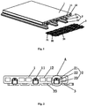
FIG. 1 is a partly exploded view ofEmbodiment 1 of the present invention; -
FIG. 2 is a main structural view ofEmbodiment 1 of the present invention; -
FIG. 3 is a close-up view of Area A ofFIG. 2 ; -
FIG. 4 is a partly exploded view ofEmbodiment 2 of the present invention; -
FIG. 5 is a main structural view ofEmbodiment 2 of the present invention; -
FIG. 6 is a close-up view of Area A' ofFIG. 5 ; - (Components In The
Drawings: 1 , Floor Tile; 2, Support Assembly; 2', Support Assembly; 3, Base Plate; 4, Heat Conducting Cable; 11, Grooves; 12, Hollow-Out Portion; 21, Heat Conducting Piece; 21', Heat Conducting Piece; 22, Reflecting Film; 23, Positioning Support; 23', Positioning Support; 231, Retaining Trough; 232, Positioning And Heat-Dissipating Fin; 31, Buckle Block; 32, Buckle Socket; 33, Positioning Notch). - The invention as well as a preferred mode of use, further objectives and advantages thereof will be best understood by reference to the following detailed description of illustrative embodiments when read in conjunction with the accompanying drawings.
- Referring to
FIG. 1 and FIG. 2 , in a first embodiment, the present invention provides a floor integrated system for working with an electric heating device. The system comprises afloor tile 1. Thefloor tile 1 has its bottom surface formed with a plurality ofgrooves 11 that are spaced and extend in parallel. Each of thegrooves 11 has a U-shaped cross-section. Thefloor tile 1 has its middle part provided with a plurality of square cross-sectional hollow-outportion 12, so as to effectively reduce weight and save material used. Thefloor tile 1 has its bottom surface connected to abase plate 3. Between each of thegrooves 11 and thebase plate 3, there is asupport assembly 2 arranged. Thesupport assembly 2 includes aheat conducting piece 21 and apositioning support 23 mounted in an up-and-down lapping mode. Between theheat conducting piece 21 and thepositioning support 23, there is a reflectingfilm 22 arranged. The reflectingfilm 22 may be a piece of aluminum foil or aluminum oxide film, so as to effectively reflect and retain the heat generated inside theheat conducting piece 21, thereby preventing overall heat energy from flowing away and thereby enhancing heat utilization. Therein, thepositioning support 23 is a rectangular cross-sectional hollow profile. The hollow profile may be made of aluminum or stainless steel or aluminum alloy, provided it is light in weight, firm in structure, and versatile. Thebase plate 3 is a net-structure plate piece, and has its top surface provided with a plurality of spacedpositioning notches 33 that correspond to thegrooves 11 of thefloor tile 1, thereby effectively positioning thesupport assembly 2 from above and from below. Such structural positioning eliminates the risk of deviation and uneven distribution of pipes caused by manual positioning during construction. Thebase plate 3 has its periphery provided withbuckle sockets 32 and buckle blocks 31. Thebuckle block 31 is a T-shaped tenon, and thebuckle socket 32 is a T-shaped mortise that meshes with thecorresponding buckle block 31. Therebyplural base plates 3 can be connected in multiple directions, so as to realize modularized installation that features accurate positioning, reduced installation time, convenient operation and high quality result. - As shown in
FIG. 3 , theheat conducting piece 21 is a semicircular cross-sectional profile, with its outer top surface fittingly nesting along the inner wall of the correspondinggroove 11. Theheat conducting piece 21 has the inner wall at the two ends of its semicircular structure provided withpositioning steps 212 and positioningwedges 213, and has the outer wall at its middle part provided with achase 211, for fittingly receiving an external heat conducting cable 4, so that the heat conducting cable 4 can contact tightly with the bottom surface of thefloor tile 1, thereby maximizing heat radiation and ensuring good warmth keeping. Thepositioning support 23 has lower parts of its two laterals provided with positioning and heat-dissipatingfins 232 that are configured to be fittingly received in thepositioning notches 33 of thebase plate 3. Thepositioning support 23 has upper parts of its two laterals provided with retainingtroughs 231 that correspond to the positioningwedges 213. The positioning steps 212 of theheat conducting piece 21 and the upper surface of thepositioning support 23 abut against and thereby retain each other. In addition, with the combination between the positioningwedges 213 and the retainingtroughs 231, theheat conducting piece 21 and thepositioning support 23 are assembled firmly. The reflectingfilm 22 arranged between the conductingpiece 21 and thepositioning support 23 further enhance overall combination. Moreover, the modularized installation is convenient to perform and ensures easy repair and replacement in the future. The replaced components can be recycled, making the system favorable to environmental protection and resource conservation. - As shown in
FIG. 4 andFIG. 5 , in a second embodiment, the present invention provides a floor integrated system working with a water heating device. The system comprises afloor tile 1, a support assembly 2' and abase plate 3. Thefloor tile 1 and thebase plate 3 are identical to their counterparts in the first embodiment, so the signal structural design are applicable to both electric heating and water heating modules, making the entire system featuring reduced components, high price-performance ratio, and possibility of convenient after service. - As shown in
FIG. 6 , the support assembly 2' includes a heat conducting piece 21' and a positioning support 23'. Between the heat conducting piece 21' and the positioning support 23' there is also a reflectingfilm 22 arranged for heat insulation and warmth keeping. The heat conducting piece 21' is a tubular profile for hot water to circulate therein and conduct heat. The positioning support 23' is a rectangular cross-sectional hollow profile having a relatively small thickness. It has lower parts at two laterals thereof provided with positioning and heat-dissipatingfins 232 that are also configured to be fittingly received in thepositioning notches 33 of thebase plate 3. By changing only two components, the system can be shifted from electric heating use to water heating use. The structural module can be disassembled to have the components replaced easily without generating any construction waste. Moreover, the floor tile structure can be recycled and reused. With the disclosed system, a floor heating structure can be used for both water heating and electric heating applications, making the product versatile and inexpensive to manufacture. Other advantages of the present invention includes convenient repair, easy installation, low frictional loss among components, high heat-transmitting capacity, good thermal and pressure resistance, excellent low temperature resistance, hot-cool dual purpose, superior qualitative stability and impact resistance, as well as promising market prospect. - The present invention has been described with reference to the preferred embodiments and it is understood that the embodiments are not intended to limit the scope of the present invention as defined by the appended claims.
Claims (8)
- A floor integrated system, comprising a floor tile (1) a support assembly and a base plate (3), wherein the floor tile (1) has a bottom surface formed with a plurality of grooves (11) and is connected to the base plate (3), wherein the support assembly (2) is arranged between the grooves (11) and the base plate (3), and the support assembly (2) includes a heat conducting piece (21) and a positioning support (23) mounted in an up-and-down lapping mode, characterized in that a reflecting film (22) is arranged between the heat conducting piece (21) and the positioning support (23), and in that the positioning support (23) is a rectangular cross-sectional hollow profile, and has lower parts at two laterals thereof provided with positioning and heat-dissipating fins (232).
- The floor integrated system of claim 1, being characterized in that: the heat conducting piece (21) is a semicircular cross-sectional profile wherein the heat conducting piece (21) has an inner wall at two ends thereof provided with positioning steps (212) and positioning wedges (213) and has outer wall at a middle part thereof provided with a chase (211) for fittingly receiving an external heat conducting cable.
- The floor integrated system of claim 2, being characterized in that: the positioning support (23) has upper parts at two laterals thereof provided with retaining troughs (231) for engaging with the positioning wedges (213).
- The floor integrated system of claim 1, being characterized in that: the heat conducting piece (21) is a tubular profile for hot water to circulate therein and conduct heat.
- The floor integrated system of claim 1, being characterized in that: the base plate (3) is a net-structure plate piece that has a top surface thereof provided with a plurality of positioning notches (33) adapted to fittingly receive the heat-dissipating fins (232) and has a periphery thereof provided with buckle sockets (32) and buckle blocks (31).
- The floor integrated system of claim 5, being characterized in that: each of the buckle blocks (31) is of a T-shaped tenon, and each of the buckle sockets (32) is a T-shaped mortise that meshes with the corresponding buckle block (31).
- The floor integrated system of claim 1, being characterized in that: the floor tile (1) has a middle part thereof provided with a plurality of square cross-sectional hollow-out portions (12).
- The floor integrated system of claim 1, being characterized in that: the groove (11) has a U-shaped cross-section.
Applications Claiming Priority (2)
| Application Number | Priority Date | Filing Date | Title |
|---|---|---|---|
| CN201310205657.7A CN103267315B (en) | 2013-05-29 | 2013-05-29 | Recycled constant-temperature ceramic floor integrated system |
| PCT/CN2013/001348 WO2014190460A1 (en) | 2013-05-29 | 2013-11-07 | Recycling constant-temperature ceramic floor integrated system |
Publications (3)
| Publication Number | Publication Date |
|---|---|
| EP2988070A1 EP2988070A1 (en) | 2016-02-24 |
| EP2988070A4 EP2988070A4 (en) | 2017-03-15 |
| EP2988070B1 true EP2988070B1 (en) | 2019-03-13 |
Family
ID=49010958
Family Applications (1)
| Application Number | Title | Priority Date | Filing Date |
|---|---|---|---|
| EP13885755.2A Active EP2988070B1 (en) | 2013-05-29 | 2013-11-07 | Floor-integrated system |
Country Status (4)
| Country | Link |
|---|---|
| US (1) | US9896843B2 (en) |
| EP (1) | EP2988070B1 (en) |
| CN (1) | CN103267315B (en) |
| WO (1) | WO2014190460A1 (en) |
Families Citing this family (26)
| Publication number | Priority date | Publication date | Assignee | Title |
|---|---|---|---|---|
| CN103267315B (en) * | 2013-05-29 | 2014-09-24 | 福建省乐普陶板制造有限公司 | Recycled constant-temperature ceramic floor integrated system |
| US10358778B2 (en) | 2015-02-06 | 2019-07-23 | Michael Gregory Theodore, Jr. | Temperature controlled structure assembly |
| CN104864455A (en) * | 2015-06-08 | 2015-08-26 | 四川省新万兴瓷业有限公司 | Bottom surface guniting floor heating brick and production process thereof |
| CN105113758A (en) * | 2015-08-28 | 2015-12-02 | 腾志理 | Antiskid floor tile |
| CN105401709B (en) * | 2015-11-30 | 2017-12-12 | 福建省乐普陶板制造有限公司 | The floor heating tiles integrated system and its rapid installation process that can be recycled |
| CN106760382B (en) * | 2016-12-14 | 2022-11-25 | 浙江亚厦装饰股份有限公司 | A modular electrothermal film floor heating composite board and its paving method |
| SE542133C2 (en) | 2017-05-22 | 2020-03-03 | Heat Click Company Ab | Heat panel, heating system and method for installing the system |
| CN107917455A (en) * | 2017-12-29 | 2018-04-17 | 福州启辰阳光建材有限公司 | One kind fever integrated floor |
| CN108301590A (en) * | 2018-03-14 | 2018-07-20 | 中山市阳日电热科技发展有限公司 | A kind of stable structure and the uniform heating floor that generates heat |
| CN108252486A (en) * | 2018-03-27 | 2018-07-06 | 上海金洛海洋工程有限公司 | Modular floor heating component |
| DE102018122813B4 (en) * | 2018-09-18 | 2021-02-25 | Airbus Operations Gmbh | Floor system for a vehicle |
| CN109577594A (en) * | 2018-11-20 | 2019-04-05 | 北京博天子睿科技有限公司 | Air conditioner floor component and its bracket, heat preservation module |
| CN109577600B (en) * | 2018-12-21 | 2020-07-17 | 变形积木(北京)科技有限公司 | Ground installation structure and method |
| CN110006094A (en) * | 2019-05-08 | 2019-07-12 | 湖州练市皇盛木业有限公司 | A kind of heating floor and its production technology of fast heating |
| DE102019114831A1 (en) * | 2019-06-03 | 2020-12-03 | Hornbach Baumarkt Ag | Floor covering with at least one connecting element |
| CN110317041B (en) * | 2019-07-10 | 2022-03-01 | 福建省乐普陶板制造有限公司 | Waste ceramic waste recovery and re-sintering ceramic plate and preparation method thereof |
| CN110259037B (en) * | 2019-07-23 | 2023-09-12 | 佛山市东鹏陶瓷有限公司 | A ceramic tile laying device and its laying method |
| CN110230379B (en) * | 2019-07-23 | 2023-10-03 | 佛山市东鹏陶瓷有限公司 | A sound-insulating ceramic tile laying device and its laying method |
| CN110607888A (en) * | 2019-09-25 | 2019-12-24 | 金螳螂精装科技(苏州)有限公司 | A tile-concrete integrated board hanging wall keel wall connection and leveling device |
| SE544813C2 (en) * | 2020-02-04 | 2022-11-29 | Satisfactory Ab | A floor system, a tile of a floor system, and an underneath segment of a floor system |
| CN112538944A (en) * | 2020-11-10 | 2021-03-23 | 东莞市唯美陶瓷工业园有限公司 | Heating ceramic tile, ceramic tile structure and preparation method of heating ceramic tile |
| DE202021101965U1 (en) * | 2021-04-12 | 2021-05-18 | ABC Keramik H & R Berentelg GmbH & Co. KG | Facade panel with heat exchanger groove |
| CN113404254A (en) * | 2021-07-20 | 2021-09-17 | 河北融舟科技发展有限公司 | Floor mounting structure at water collector |
| CN113431295A (en) * | 2021-07-31 | 2021-09-24 | 北京住总第三开发建设有限公司 | Assembly type dry method ground system construction process and floor heating protective layer |
| US11891803B1 (en) * | 2023-01-12 | 2024-02-06 | Astra Capital Incorporated | Modular platform deck for traffic |
| CN116164320A (en) * | 2023-02-22 | 2023-05-26 | 中核同辐(长春)辐射技术有限公司 | A kind of graphene radiation cross-linked geothermal pipe and preparation method thereof |
Family Cites Families (57)
| Publication number | Priority date | Publication date | Assignee | Title |
|---|---|---|---|---|
| US2799481A (en) * | 1953-07-29 | 1957-07-16 | Charles H Becker | Unit for a heating floor |
| US3795272A (en) * | 1971-04-17 | 1974-03-05 | F Kahn | Construction member for a heated floor and floor assembled therefrom |
| US4635710A (en) * | 1984-02-02 | 1987-01-13 | William Shelley | Linear radiant ceiling panel |
| US4766951A (en) * | 1984-12-13 | 1988-08-30 | Airtex Corp | Radiant, linear panels |
| US4759402A (en) * | 1987-08-17 | 1988-07-26 | Aero Tech Manufacturing Inc. | Modular construction for radiant panel |
| DE3837562C2 (en) * | 1988-11-04 | 1997-11-20 | Eht Siegmund Gmbh | Area element for a heated cavity floor |
| US5597033A (en) * | 1993-06-15 | 1997-01-28 | Cali; Philip | Baseboard heater |
| US5454428A (en) * | 1993-11-22 | 1995-10-03 | Radiant Engineering, Inc. | Hydronic radiant heat distribution panel and system |
| US5829516A (en) * | 1993-12-15 | 1998-11-03 | Aavid Thermal Products, Inc. | Liquid cooled heat sink for cooling electronic components |
| US5879491A (en) * | 1994-10-11 | 1999-03-09 | Yuki Japan Co., Ltd. | Method of installing a floor heating apparatus |
| US5862854A (en) * | 1995-01-27 | 1999-01-26 | Rhp Systems, Inc. | Radiant heating panel |
| US6910526B1 (en) * | 1995-10-06 | 2005-06-28 | Barcol-Air Ag | Contact element and ceiling element for a heating and cooling ceiling |
| DK172362B1 (en) * | 1996-10-24 | 1998-04-14 | Bjarne Kongsgaard | Heating element for a floor |
| US5931381A (en) * | 1997-05-23 | 1999-08-03 | Fiedrich; Joachim | For radiant floor, wall and ceiling hydronic heating and/or cooling systems using metal plates that are heated or cooled by attached tubing that is fed hot or cold water, techniques of improving performance and avoiding condensation when cooling |
| US6330980B1 (en) * | 1997-11-03 | 2001-12-18 | Joachim Fiedrich | Dry installation of a radiant floor or wall hydronic heating system, metal radiating plates that attach to the edges of side-by-side boards and provide metal slots for holding hot water tubing |
| JP2001020510A (en) * | 1999-07-07 | 2001-01-23 | Eidai Co Ltd | Heating flooring |
| US6283382B1 (en) * | 2000-08-15 | 2001-09-04 | Michael Fitzemeyer | Radiant heating system pipe mounting plate |
| JP2002221328A (en) * | 2001-01-25 | 2002-08-09 | Eidai Co Ltd | Heating flooring |
| US8382004B2 (en) * | 2001-04-04 | 2013-02-26 | Graftech International Holdings Inc. | Flexible graphite flooring heat spreader |
| US20040026525A1 (en) * | 2002-05-20 | 2004-02-12 | Joachim Fiedrich | In radiant wall and ceiling hydronic room heating or cooling systems, using tubing that is fed hot or cold water, the tubing is embedded in gypsum or cement wallboard in intimate thermal contact therewith so that the wallboard heats or cools the room |
| US6726115B1 (en) * | 2003-01-13 | 2004-04-27 | Watts Radiant, Inc. | Radiant heating system for subfloor installation |
| CA2466624C (en) * | 2003-05-07 | 2007-01-02 | Dale H. Pickard | Hydronic radiant heat tubing receptacle and heat distribution panel system |
| US6969832B1 (en) * | 2003-05-19 | 2005-11-29 | Daughtry Sr Timothy Douglas | Radiant floor heating and cooling system clip |
| ITBL20030007A1 (en) * | 2003-05-30 | 2004-11-30 | Rold Adelio Da | HEATING SYSTEM WITH VECTOR FLUID DISTRIBUTED IN FINISHED FLOORING PLANKS. |
| US7406801B2 (en) * | 2004-02-04 | 2008-08-05 | Karl Zeng | Watertight decking |
| JP3660350B1 (en) * | 2004-07-23 | 2005-06-15 | スリー・アール・テック・ジャパン株式会社 | Heat exchanger and air conditioner |
| CA2622582A1 (en) * | 2005-09-14 | 2007-03-22 | Uponor, Inc. | Radiant heating system and method |
| US7900416B1 (en) * | 2006-03-30 | 2011-03-08 | Connor Sport Court International, Inc. | Floor tile with load bearing lattice |
| US7832159B1 (en) * | 2006-06-06 | 2010-11-16 | Kayhart Paul H | Radiant in-floor heating system |
| US20090294601A1 (en) * | 2006-06-09 | 2009-12-03 | Asker Hojlund Pedersen | Mounting Clamp For A Floor Heating System |
| US8020783B2 (en) * | 2006-07-19 | 2011-09-20 | Backman Jr James Joseph | Radiant mat grid |
| DE202006015397U1 (en) * | 2006-10-04 | 2006-12-07 | Blanke Gmbh & Co. Kg | Multilayer structure system e.g. for flooring of underfloor heating, has under and lateral plate formed construction unit for admission of pipes of under-floor heating and on surface of plate construction unit uncoupling mat is arranged |
| US8025240B2 (en) * | 2006-10-19 | 2011-09-27 | Keller Komfort Radiant Systems, Inc. | Radiant heat flooring system |
| US7992623B2 (en) * | 2007-01-10 | 2011-08-09 | Keller Komfort Radiant Systems, Inc. | Radiant heat wall covering system |
| ITBO20070096A1 (en) * | 2007-02-20 | 2008-08-21 | Paolo Campagna | HEAT EXCHANGE SYSTEM, MODULAR, MODULAR AND LIMITED INPUT, PARTICULARLY SUITABLE FOR AIR CONDITIONING OF ENVIRONMENTS. |
| DE102007011194B3 (en) * | 2007-03-06 | 2008-09-04 | Winkler, Wolfram, Dipl.-Ing. Dr. | Locating clip for pipes in under-floor central heating system has two sets of jaws separated by a wire insertion gap |
| US8256690B2 (en) * | 2007-04-27 | 2012-09-04 | Talbott Solar And Radiant Homes, Inc. | Radiant heating and cooling panel |
| US20100300028A1 (en) * | 2007-12-18 | 2010-12-02 | Innovation Central Pty Ltd | Improved protection barrier and components thereof |
| US8499823B1 (en) * | 2008-04-18 | 2013-08-06 | One Source | Twin heat transfer tubing retention panel |
| US20100237157A1 (en) * | 2009-03-21 | 2010-09-23 | Zhaojun Guo | Ground heating flooring with internal heating conduction structure |
| IT1393538B1 (en) * | 2009-03-27 | 2012-04-27 | Messana | MODULAR PREFABRICATED RADIANT PANEL WITH BUILT-IN COLLECTORS. |
| US8650832B2 (en) * | 2010-03-24 | 2014-02-18 | Joachim Fiedrich | In-wall hydronic thermal control system and installation method |
| US9091489B2 (en) * | 2010-05-14 | 2015-07-28 | Paragon Space Development Corporation | Radiator systems |
| US9404665B1 (en) * | 2010-08-30 | 2016-08-02 | Khart Panels LLC | Radiant panel system having increased efficiency |
| US8881476B2 (en) * | 2011-04-25 | 2014-11-11 | BTU Comfort Systems, LLC. | Panels having multiple channel structures |
| EP2679485B1 (en) * | 2012-06-26 | 2016-08-10 | Airbus Operations GmbH | Floor panel with integrated cable channel |
| CN103062825B (en) * | 2013-02-01 | 2015-02-25 | 卡尔玛地板(苏州)有限公司 | Heat energy floor |
| KR101294934B1 (en) | 2013-03-13 | 2013-08-08 | 김혜정 | Korean floor heating system |
| CN203385082U (en) | 2013-05-29 | 2014-01-08 | 福建省乐普陶板制造有限公司 | Trough structure capable of effectively improving heat energy efficiency |
| CN203385086U (en) | 2013-05-29 | 2014-01-08 | 福建省乐普陶板制造有限公司 | Positioning structure capable of effectively insulating heat |
| CN203385065U (en) * | 2013-05-29 | 2014-01-08 | 福建省乐普陶板制造有限公司 | Recycled constant temperature ceramic floor integrated system |
| CN203347181U (en) | 2013-05-29 | 2013-12-18 | 福建省乐普陶板制造有限公司 | Thermal insulation dampproof and soundproof base plate support |
| CN203385085U (en) | 2013-05-29 | 2014-01-08 | 福建省乐普陶板制造有限公司 | Mounting protective structure for heat conduction cable |
| CN103267315B (en) | 2013-05-29 | 2014-09-24 | 福建省乐普陶板制造有限公司 | Recycled constant-temperature ceramic floor integrated system |
| US8973328B2 (en) * | 2013-07-12 | 2015-03-10 | Macneil Ip Llc | Floor tile expansion joint |
| US10458727B2 (en) * | 2013-11-18 | 2019-10-29 | Bruce Gregory | Heat transfer using flexible fluid conduit |
| US20150225962A1 (en) * | 2014-02-07 | 2015-08-13 | Crane Composites, Inc. | Interlocking panel system |
-
2013
- 2013-05-29 CN CN201310205657.7A patent/CN103267315B/en not_active Expired - Fee Related
- 2013-11-07 WO PCT/CN2013/001348 patent/WO2014190460A1/en not_active Ceased
- 2013-11-07 US US14/894,351 patent/US9896843B2/en active Active
- 2013-11-07 EP EP13885755.2A patent/EP2988070B1/en active Active
Non-Patent Citations (1)
| Title |
|---|
| None * |
Also Published As
| Publication number | Publication date |
|---|---|
| EP2988070A1 (en) | 2016-02-24 |
| WO2014190460A1 (en) | 2014-12-04 |
| CN103267315A (en) | 2013-08-28 |
| CN103267315B (en) | 2014-09-24 |
| US20160115691A1 (en) | 2016-04-28 |
| EP2988070A4 (en) | 2017-03-15 |
| US9896843B2 (en) | 2018-02-20 |
Similar Documents
| Publication | Publication Date | Title |
|---|---|---|
| US9896843B2 (en) | Recycling constant-temperature ceramic floor integrated system | |
| CN103262262B (en) | Hybrid Solar Panel | |
| US20140096763A1 (en) | Modular, fluid thermal transfer device | |
| CA2837373C (en) | Modular, fluid thermal transfer device | |
| US20140076514A1 (en) | Modular heating structure that can be fitted to the interior walls of buildings | |
| KR20140037701A (en) | Heat transfer panel for heating prefabricated | |
| KR101654126B1 (en) | Method for constructing ondol flooring of building and apartment house | |
| KR20160064927A (en) | Heat source pipe, and floor heating and cooling system | |
| RU2552975C2 (en) | Floor heating (cooling) system | |
| JP5921891B2 (en) | Panel heat exchanger for underground heat source heat pump | |
| CN105066233A (en) | Skirting type heating radiator using air energy | |
| CN104633808A (en) | Heating and cooling dualpurpose floor heating module | |
| JP2011174659A (en) | Heat storage type warm water floor heating device | |
| CN111692627A (en) | Base plate and underfloor heating system for heating containing guide module | |
| CN105042680B (en) | Air energy radiator | |
| CN209194841U (en) | A kind of novel energy-conserving building materials | |
| CN211977000U (en) | Floor radiation heating system based on micro heat pipe array | |
| JP2013117327A (en) | Ultra-lightweight solar energy utilization system | |
| EP3736503B1 (en) | Flexible water-based wall-surface heating and cooling system | |
| KR101110690B1 (en) | the soler collector using a heat pipe with a circulation circuit on the inside | |
| JP6505471B2 (en) | Underfloor temperature control system and building | |
| CN205688750U (en) | A kind of temperature control floor | |
| CN204901928U (en) | Adopt ground payment to a porter formula heating radiator of air ability | |
| CN215112889U (en) | High-efficiency radiation cooling and heating plate | |
| CN217635839U (en) | Floor heating installation structure convenient to install |
Legal Events
| Date | Code | Title | Description |
|---|---|---|---|
| PUAI | Public reference made under article 153(3) epc to a published international application that has entered the european phase |
Free format text: ORIGINAL CODE: 0009012 |
|
| 17P | Request for examination filed |
Effective date: 20151117 |
|
| AK | Designated contracting states |
Kind code of ref document: A1 Designated state(s): AL AT BE BG CH CY CZ DE DK EE ES FI FR GB GR HR HU IE IS IT LI LT LU LV MC MK MT NL NO PL PT RO RS SE SI SK SM TR |
|
| AX | Request for extension of the european patent |
Extension state: BA ME |
|
| DAX | Request for extension of the european patent (deleted) | ||
| A4 | Supplementary search report drawn up and despatched |
Effective date: 20170210 |
|
| RIC1 | Information provided on ipc code assigned before grant |
Ipc: E04F 15/08 20060101ALI20170206BHEP Ipc: F24D 13/02 20060101AFI20170206BHEP Ipc: F24D 3/14 20060101ALI20170206BHEP Ipc: E04F 15/18 20060101ALI20170206BHEP |
|
| STAA | Information on the status of an ep patent application or granted ep patent |
Free format text: STATUS: EXAMINATION IS IN PROGRESS |
|
| 17Q | First examination report despatched |
Effective date: 20171201 |
|
| GRAP | Despatch of communication of intention to grant a patent |
Free format text: ORIGINAL CODE: EPIDOSNIGR1 |
|
| STAA | Information on the status of an ep patent application or granted ep patent |
Free format text: STATUS: GRANT OF PATENT IS INTENDED |
|
| INTG | Intention to grant announced |
Effective date: 20180717 |
|
| RIN1 | Information on inventor provided before grant (corrected) |
Inventor name: WU, JINYI Inventor name: PENG, XINGHUA Inventor name: ZHANG, MOUSEN |
|
| GRAJ | Information related to disapproval of communication of intention to grant by the applicant or resumption of examination proceedings by the epo deleted |
Free format text: ORIGINAL CODE: EPIDOSDIGR1 |
|
| GRAP | Despatch of communication of intention to grant a patent |
Free format text: ORIGINAL CODE: EPIDOSNIGR1 |
|
| INTG | Intention to grant announced |
Effective date: 20181004 |
|
| GRAS | Grant fee paid |
Free format text: ORIGINAL CODE: EPIDOSNIGR3 |
|
| GRAA | (expected) grant |
Free format text: ORIGINAL CODE: 0009210 |
|
| STAA | Information on the status of an ep patent application or granted ep patent |
Free format text: STATUS: THE PATENT HAS BEEN GRANTED |
|
| AK | Designated contracting states |
Kind code of ref document: B1 Designated state(s): AL AT BE BG CH CY CZ DE DK EE ES FI FR GB GR HR HU IE IS IT LI LT LU LV MC MK MT NL NO PL PT RO RS SE SI SK SM TR |
|
| REG | Reference to a national code |
Ref country code: GB Ref legal event code: FG4D |
|
| REG | Reference to a national code |
Ref country code: CH Ref legal event code: EP Ref country code: AT Ref legal event code: REF Ref document number: 1108237 Country of ref document: AT Kind code of ref document: T Effective date: 20190315 |
|
| REG | Reference to a national code |
Ref country code: IE Ref legal event code: FG4D |
|
| REG | Reference to a national code |
Ref country code: DE Ref legal event code: R096 Ref document number: 602013052486 Country of ref document: DE |
|
| REG | Reference to a national code |
Ref country code: NL Ref legal event code: MP Effective date: 20190313 |
|
| REG | Reference to a national code |
Ref country code: LT Ref legal event code: MG4D |
|
| PG25 | Lapsed in a contracting state [announced via postgrant information from national office to epo] |
Ref country code: SE Free format text: LAPSE BECAUSE OF FAILURE TO SUBMIT A TRANSLATION OF THE DESCRIPTION OR TO PAY THE FEE WITHIN THE PRESCRIBED TIME-LIMIT Effective date: 20190313 Ref country code: NO Free format text: LAPSE BECAUSE OF FAILURE TO SUBMIT A TRANSLATION OF THE DESCRIPTION OR TO PAY THE FEE WITHIN THE PRESCRIBED TIME-LIMIT Effective date: 20190613 Ref country code: FI Free format text: LAPSE BECAUSE OF FAILURE TO SUBMIT A TRANSLATION OF THE DESCRIPTION OR TO PAY THE FEE WITHIN THE PRESCRIBED TIME-LIMIT Effective date: 20190313 Ref country code: LT Free format text: LAPSE BECAUSE OF FAILURE TO SUBMIT A TRANSLATION OF THE DESCRIPTION OR TO PAY THE FEE WITHIN THE PRESCRIBED TIME-LIMIT Effective date: 20190313 |
|
| PG25 | Lapsed in a contracting state [announced via postgrant information from national office to epo] |
Ref country code: BG Free format text: LAPSE BECAUSE OF FAILURE TO SUBMIT A TRANSLATION OF THE DESCRIPTION OR TO PAY THE FEE WITHIN THE PRESCRIBED TIME-LIMIT Effective date: 20190613 Ref country code: GR Free format text: LAPSE BECAUSE OF FAILURE TO SUBMIT A TRANSLATION OF THE DESCRIPTION OR TO PAY THE FEE WITHIN THE PRESCRIBED TIME-LIMIT Effective date: 20190614 Ref country code: NL Free format text: LAPSE BECAUSE OF FAILURE TO SUBMIT A TRANSLATION OF THE DESCRIPTION OR TO PAY THE FEE WITHIN THE PRESCRIBED TIME-LIMIT Effective date: 20190313 Ref country code: LV Free format text: LAPSE BECAUSE OF FAILURE TO SUBMIT A TRANSLATION OF THE DESCRIPTION OR TO PAY THE FEE WITHIN THE PRESCRIBED TIME-LIMIT Effective date: 20190313 Ref country code: HR Free format text: LAPSE BECAUSE OF FAILURE TO SUBMIT A TRANSLATION OF THE DESCRIPTION OR TO PAY THE FEE WITHIN THE PRESCRIBED TIME-LIMIT Effective date: 20190313 Ref country code: RS Free format text: LAPSE BECAUSE OF FAILURE TO SUBMIT A TRANSLATION OF THE DESCRIPTION OR TO PAY THE FEE WITHIN THE PRESCRIBED TIME-LIMIT Effective date: 20190313 |
|
| REG | Reference to a national code |
Ref country code: AT Ref legal event code: MK05 Ref document number: 1108237 Country of ref document: AT Kind code of ref document: T Effective date: 20190313 |
|
| PG25 | Lapsed in a contracting state [announced via postgrant information from national office to epo] |
Ref country code: RO Free format text: LAPSE BECAUSE OF FAILURE TO SUBMIT A TRANSLATION OF THE DESCRIPTION OR TO PAY THE FEE WITHIN THE PRESCRIBED TIME-LIMIT Effective date: 20190313 Ref country code: AL Free format text: LAPSE BECAUSE OF FAILURE TO SUBMIT A TRANSLATION OF THE DESCRIPTION OR TO PAY THE FEE WITHIN THE PRESCRIBED TIME-LIMIT Effective date: 20190313 Ref country code: CZ Free format text: LAPSE BECAUSE OF FAILURE TO SUBMIT A TRANSLATION OF THE DESCRIPTION OR TO PAY THE FEE WITHIN THE PRESCRIBED TIME-LIMIT Effective date: 20190313 Ref country code: IT Free format text: LAPSE BECAUSE OF FAILURE TO SUBMIT A TRANSLATION OF THE DESCRIPTION OR TO PAY THE FEE WITHIN THE PRESCRIBED TIME-LIMIT Effective date: 20190313 Ref country code: EE Free format text: LAPSE BECAUSE OF FAILURE TO SUBMIT A TRANSLATION OF THE DESCRIPTION OR TO PAY THE FEE WITHIN THE PRESCRIBED TIME-LIMIT Effective date: 20190313 Ref country code: ES Free format text: LAPSE BECAUSE OF FAILURE TO SUBMIT A TRANSLATION OF THE DESCRIPTION OR TO PAY THE FEE WITHIN THE PRESCRIBED TIME-LIMIT Effective date: 20190313 Ref country code: PT Free format text: LAPSE BECAUSE OF FAILURE TO SUBMIT A TRANSLATION OF THE DESCRIPTION OR TO PAY THE FEE WITHIN THE PRESCRIBED TIME-LIMIT Effective date: 20190713 Ref country code: SK Free format text: LAPSE BECAUSE OF FAILURE TO SUBMIT A TRANSLATION OF THE DESCRIPTION OR TO PAY THE FEE WITHIN THE PRESCRIBED TIME-LIMIT Effective date: 20190313 |
|
| PG25 | Lapsed in a contracting state [announced via postgrant information from national office to epo] |
Ref country code: PL Free format text: LAPSE BECAUSE OF FAILURE TO SUBMIT A TRANSLATION OF THE DESCRIPTION OR TO PAY THE FEE WITHIN THE PRESCRIBED TIME-LIMIT Effective date: 20190313 Ref country code: SM Free format text: LAPSE BECAUSE OF FAILURE TO SUBMIT A TRANSLATION OF THE DESCRIPTION OR TO PAY THE FEE WITHIN THE PRESCRIBED TIME-LIMIT Effective date: 20190313 |
|
| REG | Reference to a national code |
Ref country code: DE Ref legal event code: R097 Ref document number: 602013052486 Country of ref document: DE |
|
| PG25 | Lapsed in a contracting state [announced via postgrant information from national office to epo] |
Ref country code: IS Free format text: LAPSE BECAUSE OF FAILURE TO SUBMIT A TRANSLATION OF THE DESCRIPTION OR TO PAY THE FEE WITHIN THE PRESCRIBED TIME-LIMIT Effective date: 20190713 Ref country code: AT Free format text: LAPSE BECAUSE OF FAILURE TO SUBMIT A TRANSLATION OF THE DESCRIPTION OR TO PAY THE FEE WITHIN THE PRESCRIBED TIME-LIMIT Effective date: 20190313 |
|
| PLBE | No opposition filed within time limit |
Free format text: ORIGINAL CODE: 0009261 |
|
| STAA | Information on the status of an ep patent application or granted ep patent |
Free format text: STATUS: NO OPPOSITION FILED WITHIN TIME LIMIT |
|
| PG25 | Lapsed in a contracting state [announced via postgrant information from national office to epo] |
Ref country code: DK Free format text: LAPSE BECAUSE OF FAILURE TO SUBMIT A TRANSLATION OF THE DESCRIPTION OR TO PAY THE FEE WITHIN THE PRESCRIBED TIME-LIMIT Effective date: 20190313 |
|
| 26N | No opposition filed |
Effective date: 20191216 |
|
| PG25 | Lapsed in a contracting state [announced via postgrant information from national office to epo] |
Ref country code: SI Free format text: LAPSE BECAUSE OF FAILURE TO SUBMIT A TRANSLATION OF THE DESCRIPTION OR TO PAY THE FEE WITHIN THE PRESCRIBED TIME-LIMIT Effective date: 20190313 |
|
| PG25 | Lapsed in a contracting state [announced via postgrant information from national office to epo] |
Ref country code: TR Free format text: LAPSE BECAUSE OF FAILURE TO SUBMIT A TRANSLATION OF THE DESCRIPTION OR TO PAY THE FEE WITHIN THE PRESCRIBED TIME-LIMIT Effective date: 20190313 |
|
| REG | Reference to a national code |
Ref country code: CH Ref legal event code: PL |
|
| PG25 | Lapsed in a contracting state [announced via postgrant information from national office to epo] |
Ref country code: LI Free format text: LAPSE BECAUSE OF NON-PAYMENT OF DUE FEES Effective date: 20191130 Ref country code: CH Free format text: LAPSE BECAUSE OF NON-PAYMENT OF DUE FEES Effective date: 20191130 Ref country code: LU Free format text: LAPSE BECAUSE OF NON-PAYMENT OF DUE FEES Effective date: 20191107 Ref country code: MC Free format text: LAPSE BECAUSE OF FAILURE TO SUBMIT A TRANSLATION OF THE DESCRIPTION OR TO PAY THE FEE WITHIN THE PRESCRIBED TIME-LIMIT Effective date: 20190313 |
|
| REG | Reference to a national code |
Ref country code: BE Ref legal event code: MM Effective date: 20191130 |
|
| GBPC | Gb: european patent ceased through non-payment of renewal fee |
Effective date: 20191107 |
|
| PG25 | Lapsed in a contracting state [announced via postgrant information from national office to epo] |
Ref country code: GB Free format text: LAPSE BECAUSE OF NON-PAYMENT OF DUE FEES Effective date: 20191107 Ref country code: FR Free format text: LAPSE BECAUSE OF NON-PAYMENT OF DUE FEES Effective date: 20191130 Ref country code: IE Free format text: LAPSE BECAUSE OF NON-PAYMENT OF DUE FEES Effective date: 20191107 |
|
| PG25 | Lapsed in a contracting state [announced via postgrant information from national office to epo] |
Ref country code: BE Free format text: LAPSE BECAUSE OF NON-PAYMENT OF DUE FEES Effective date: 20191130 |
|
| PG25 | Lapsed in a contracting state [announced via postgrant information from national office to epo] |
Ref country code: CY Free format text: LAPSE BECAUSE OF FAILURE TO SUBMIT A TRANSLATION OF THE DESCRIPTION OR TO PAY THE FEE WITHIN THE PRESCRIBED TIME-LIMIT Effective date: 20190313 |
|
| PG25 | Lapsed in a contracting state [announced via postgrant information from national office to epo] |
Ref country code: HU Free format text: LAPSE BECAUSE OF FAILURE TO SUBMIT A TRANSLATION OF THE DESCRIPTION OR TO PAY THE FEE WITHIN THE PRESCRIBED TIME-LIMIT; INVALID AB INITIO Effective date: 20131107 Ref country code: MT Free format text: LAPSE BECAUSE OF FAILURE TO SUBMIT A TRANSLATION OF THE DESCRIPTION OR TO PAY THE FEE WITHIN THE PRESCRIBED TIME-LIMIT Effective date: 20190313 |
|
| PG25 | Lapsed in a contracting state [announced via postgrant information from national office to epo] |
Ref country code: MK Free format text: LAPSE BECAUSE OF FAILURE TO SUBMIT A TRANSLATION OF THE DESCRIPTION OR TO PAY THE FEE WITHIN THE PRESCRIBED TIME-LIMIT Effective date: 20190313 |
|
| PGFP | Annual fee paid to national office [announced via postgrant information from national office to epo] |
Ref country code: DE Payment date: 20251217 Year of fee payment: 13 |