EP2987906B1 - Pinned fly ring for rotary drum washer and method of manufacture - Google Patents
Pinned fly ring for rotary drum washer and method of manufacture Download PDFInfo
- Publication number
- EP2987906B1 EP2987906B1 EP15181937.2A EP15181937A EP2987906B1 EP 2987906 B1 EP2987906 B1 EP 2987906B1 EP 15181937 A EP15181937 A EP 15181937A EP 2987906 B1 EP2987906 B1 EP 2987906B1
- Authority
- EP
- European Patent Office
- Prior art keywords
- ring
- holes
- diameter
- fly
- fastener
- Prior art date
- Legal status (The legal status is an assumption and is not a legal conclusion. Google has not performed a legal analysis and makes no representation as to the accuracy of the status listed.)
- Active
Links
Images


Classifications
-
- D—TEXTILES; PAPER
- D21—PAPER-MAKING; PRODUCTION OF CELLULOSE
- D21D—TREATMENT OF THE MATERIALS BEFORE PASSING TO THE PAPER-MAKING MACHINE
- D21D1/00—Methods of beating or refining; Beaters of the Hollander type
- D21D1/20—Methods of refining
- D21D1/40—Washing the fibres
Definitions
- the present invention relates to a rotary drum filtering apparatus, and more particularly to the drum structure of a rotary drum filtering apparatus, such as, for example, rotary drum filters, thickeners, washers and the like of the type employed for filtering a slurry such as pulp stock.
- a rotary drum filtering apparatus such as, for example, rotary drum filters, thickeners, washers and the like of the type employed for filtering a slurry such as pulp stock.
- a rotary drum filtering apparatus of this general type has included a drum structure that supports a circumferential filter medium and contains filtrate compartments communicating with the openings in the filter medium for receiving liquid drained through the latter.
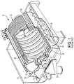
- FIG. 1 A rotary drum filtering apparatus, such as a rotary drum washer 10, is illustrated in FIG. 1 .
- the traditional vacuum drum washer 10 includes a tank 14 having a baffled inlet box 18 and an inlet lip 22. Pulp entering the drum washer 10 passes over the lip 22 into an area 26 around a central drum 30.
- the central drum 30 is comprised of a plurality of fly rings 34 held together spaced apart, the outer circumference of the drum supporting washer decking 38. Pulp accumulates on the decking 38 and then is removed from the decking by a takeoff 42.
- the takeoff 42 deposits the pulp into an area 46 where a repulper 50 transports the pulp for further processing.
- the fly ring is an integral part of the rotary washer drum's structure. It is located on the inside of the drum and its purpose is to maintain the round cross-section required to resist the loading seen by the drum while in operation.
- the manufacturing process to make a fly ring 34 has been stagnating for decades.
- the traditional rotary drum washer fly ring manufacturing methods involve laser cutting, welding, machining, and straightening. Although laser cutting is used, the laser cutting, together with further processing, has not produced fly ring with an outer circumference within needed tight tolerances.
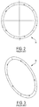
- This prior fly ring construction illustrated in FIGS. 2 and 3 consisted of 5 laser cut segments that were assembled by grinding a weld preparation on each end of each ring segment, welding the ring segment ends together, grinding the weld, and then straightening the ring. The fly ring would then be machined to the proper finished outside diameter. This process is extremely labor intensive.
- this ring involves the following steps:
- the new manufacturing method of this disclosure takes advantage of the accuracy of an improved method of laser cutting and eliminates welding, machining, and straightening while maintaining very tight tolerances.
- the new method also uses a specially designed custom fastener that secures the fly ring segments together to form a precise ring. Elimination of the weld allows the fly ring to be assembled by a non-skilled tradesperson in a fraction of the time.
- the fly ring comprises a plurality of ring segments, each ring segment being laser cut. Each ring segment has a first end which overlaps a second end of an adjacent ring segment, forming a lapped joint. Each ring segment first and second end has at least two spaced apart through-holes, the through-holes of the first end being aligned with the through-holes of the second end.
- a custom fastener extends through the first end and second end aligned through-holes.
- FIGS. 4 through 8 of the drawings Illustrated in the FIGS. 4 through 8 of the drawings is a fly ring 100 adapted to be used in a rotary drum washer, such as the one illustrated in FIG. 1 , the fly ring 100 comprising a plurality of ring segments 104.
- each ring segment 104 is identical to each other, but in other embodiments (not shown), each ring segment length can be different.
- Each ring segment 104 is laser cut, and, as illustrated in FIGS. 4, 5 , 6 and 8B , has a first end 108 which overlaps a second end 112 of an adjacent ring segment, forming a lapped joint 116. As illustrated in FIGS.
- each ring segment first and second end has at least two spaced apart through-holes 120 and 124, the through-holes of the first end being aligned with the through-holes of the second end.
- a custom fastener 130 extends through the first end and second end aligned through-holes.
- the custom fastener 130 comprises a bolt with a head 134 on one side of the lapped joint 116, and a washer 140 and a nut 144 on the other side of the lapped joint 116.
- the method comprises the following steps. First, laser cutting the plurality of arc shaped ring segments 104 out of a metal plate, each ring segment 104 having an outer circumference dimension within a predetermined tight tolerance. At least two through-holes 120 and 124 are also laser cut into each end of each segment 104.
- the ends of the ring segments 104 are then overlapped so that the assembled ring segments form a complete fly ring 100. Because of the tight tolerance cut dimension of the outer arc of each ring segment 104, the ring 100 has a predetermined outer circumference within a given tight tolerance.
- the custom fastener 130 is driven through each of the at least two through-holes in each end of each ring segment.
- the custom fastener 130 is then secured in each hole by placing the washer 140 and threading the nut 144 onto the end of the fastener 130, so that the assembled segments form the ring 100.
- the alignment of the edges of the inner circumference of the ring segments is not crucial, but the alignment of the outer circumference of the ring segments is.
- the custom fastener 130 comprises a bolt having the head 134.
- the custom fastener 130 also includes a first diameter portion 150 adjacent the head 134 and with a first diameter, and a neck portion 154 adjacent the first diameter portion 150 with a smaller diameter than the first diameter.
- the custom fastener 130 also includes a third threaded diameter portion 158 adjacent the neck portion 154, the third diameter portion 158 having a third diameter greater than the neck portion diameter and less than the first diameter.
- the end of the first diameter portion adjacent the neck portion has a first lead-in chamfer 160, and the end of the custom fastener opposite the head end has a lead-in chamfer 164.
- Each of these lead-in chamfers aid in securing the ring segments together by accommodating and realigning any misalignment in the through-holes in the end of the rings segments.
- the disclosed process modifies conventional laser cutting to improve its precision so that the laser cut segments can be used to form a properly dimensioned drum. More particularly, in the disclosed process, the laser cutting is speed optimized to obtain the desired tolerance and finish. The speed will vary depending on the material and power of the laser. This improved laser cutting permits the precision needed to accurately cut the ring segments. The ring segments can then be joined at a lap joint to form the precise shape needed for the drum.
- This pinned fly ring takes advantage of this high precision laser cutting process and eliminates the need for welding, straightening, and machining while not compromising structural integrity.
- the new design comprises laser cut ring segments and custom designed fasteners. Unlike the traditional fly ring, the joints are lap joints with pre-laser cut holes.
- the joints between the ring segments are overlapped.
- the holes cut by laser cutting are then aligned.
- a custom faster is then used to secure the lapped segment ends to one another.
- the custom fastener includes a chamfered portion which forces the aligned openings to orient themselves so the precise drum outer circumference can be achieved.
- the custom fastener is used to maintain the tight tolerance required between the hole and the shank of the bolt.
- Typical purchased fasteners do not have the high tolerance required to get the proper fit.
- the neck portion between the fastener head and the threaded shank is a thread run-out groove. Because it is impossible to thread completely to a shoulder, the groove provides a means to end the thread and still tighten the nut completely.
- the custom designed fasteners are driven into place and secured by a nut.
- the assembly process comprises three easy steps.
- the new assembly process can be completed in a fraction of the time and does not require special skill (such as welding) to complete.
Landscapes
- Paper (AREA)
- Laser Beam Processing (AREA)
Description
- The present invention relates to a rotary drum filtering apparatus, and more particularly to the drum structure of a rotary drum filtering apparatus, such as, for example, rotary drum filters, thickeners, washers and the like of the type employed for filtering a slurry such as pulp stock.
- Conventionally, a rotary drum filtering apparatus of this general type has included a drum structure that supports a circumferential filter medium and contains filtrate compartments communicating with the openings in the filter medium for receiving liquid drained through the latter.
- A rotary drum filtering apparatus, such as a
rotary drum washer 10, is illustrated inFIG. 1 . The traditionalvacuum drum washer 10 includes atank 14 having a baffledinlet box 18 and aninlet lip 22. Pulp entering thedrum washer 10 passes over thelip 22 into anarea 26 around acentral drum 30. Thecentral drum 30 is comprised of a plurality offly rings 34 held together spaced apart, the outer circumference of the drum supportingwasher decking 38. Pulp accumulates on thedecking 38 and then is removed from the decking by atakeoff 42. Thetakeoff 42 deposits the pulp into anarea 46 where arepulper 50 transports the pulp for further processing. - The fly ring is an integral part of the rotary washer drum's structure. It is located on the inside of the drum and its purpose is to maintain the round cross-section required to resist the loading seen by the drum while in operation.
- The manufacturing process to make a
fly ring 34 has been stagnating for decades. The traditional rotary drum washer fly ring manufacturing methods involve laser cutting, welding, machining, and straightening. Although laser cutting is used, the laser cutting, together with further processing, has not produced fly ring with an outer circumference within needed tight tolerances. - This prior fly ring construction illustrated in
FIGS. 2 and 3 consisted of 5 laser cut segments that were assembled by grinding a weld preparation on each end of each ring segment, welding the ring segment ends together, grinding the weld, and then straightening the ring. The fly ring would then be machined to the proper finished outside diameter. This process is extremely labor intensive. - More particularly, the manufacturing of this ring involves the following steps:
- 1.
- Cut sections of the ring out of raw plate.
- 2.
- Produce weld preparations of both sides of the ring sections.
- 3.
- Position/ Fixture the plates.
- 4.
- Weld each joint on one side.
- 5.
- Grind weld flat.
- 6.
- Flip over ring.
- 7.
- Weld each joint on opposite side.
- 8.
- Grind weld flat.
- 9.
- Straighten ring.
- 10.
- Machine outside diameter to finished dimension.
- The new manufacturing method of this disclosure takes advantage of the accuracy of an improved method of laser cutting and eliminates welding, machining, and straightening while maintaining very tight tolerances. The new method also uses a specially designed custom fastener that secures the fly ring segments together to form a precise ring. Elimination of the weld allows the fly ring to be assembled by a non-skilled tradesperson in a fraction of the time.
- More particularly, disclosed is a fly ring adapted to be used in a rotary drum filtering apparatus, and a method of forming such a fly ring. The fly ring comprises a plurality of ring segments, each ring segment being laser cut. Each ring segment has a first end which overlaps a second end of an adjacent ring segment, forming a lapped joint. Each ring segment first and second end has at least two spaced apart through-holes, the through-holes of the first end being aligned with the through-holes of the second end. A custom fastener extends through the first end and second end aligned through-holes.
-
-
FIG. 1 is a perspective view of a pulp vacuum washer. -
FIG. 2 is a top view of a prior art concentric ring. -
FIG. 3 is a perspective view of the ring shown inFIG. 2 . -
FIG. 4 is a side view of an overlapping joint of a fly ring according to this disclosure. -
FIG. 5 is a top view of the joint ofFIG. 4 . -
FIG. 6 is a bottom view of the overlapping joint ofFIG. 4 . -
FIG. 7A is a side view of a custom fastener used to connect the two ring segments. -
FIG. 7B is an end view of the custom fastener shown inFIG. 7A . -
FIG. 8A is an enlarged view of a pinned fly ring according to this disclosure. -
FIG. 8B is a side view of the ring shown inFIG. 8A . -
FIG. 8C is a cross-section of the overlapping joint of the ring segments shown inFIG. 8A . - Before one embodiment of the disclosure is explained in detail, it is to be understood that the disclosure is not limited in its application to the details of the construction and the arrangements of components set forth in the following description or illustrated in the drawings. The disclosure is capable of other embodiments and of being practiced or being carried out in various ways. Also, it is to be understood that the phraseology and terminology used herein is for the purpose of description and should not be regarded as limiting. Use of "including" and "comprising" and variations thereof as used herein is meant to encompass the items listed thereafter and equivalents thereof as well as additional items. Use of "consisting of" and variations thereof as used herein is meant to encompass only the items listed thereafter and equivalents thereof. Further, it is to be understood that such terms as "forward", "rearward", "left", "right", "upward", "downward", "side", "top" and "bottom", etc., are words of convenience and are not to be construed as limiting terms.
- Illustrated in the
FIGS. 4 through 8 of the drawings is afly ring 100 adapted to be used in a rotary drum washer, such as the one illustrated inFIG. 1 , thefly ring 100 comprising a plurality ofring segments 104. In the disclosedfly ring 100, eachring segment 104 is identical to each other, but in other embodiments (not shown), each ring segment length can be different. Eachring segment 104 is laser cut, and, as illustrated inFIGS. 4, 5 ,6 and8B , has afirst end 108 which overlaps asecond end 112 of an adjacent ring segment, forming a lapped joint 116. As illustrated inFIGS. 8A, 8B and 8C , each ring segment first and second end has at least two spaced apart through-holes custom fastener 130 extends through the first end and second end aligned through-holes. Thecustom fastener 130 comprises a bolt with ahead 134 on one side of the lapped joint 116, and awasher 140 and anut 144 on the other side of the lapped joint 116. - Also disclosed is a method of forming the
fly ring 100 for a rotary drum washer. The method comprises the following steps. First, laser cutting the plurality of arc shapedring segments 104 out of a metal plate, eachring segment 104 having an outer circumference dimension within a predetermined tight tolerance. At least two through-holes segment 104. - The ends of the
ring segments 104 are then overlapped so that the assembled ring segments form acomplete fly ring 100. Because of the tight tolerance cut dimension of the outer arc of eachring segment 104, thering 100 has a predetermined outer circumference within a given tight tolerance. - After overlapping one ring segment end over another ring segment end, the
custom fastener 130 is driven through each of the at least two through-holes in each end of each ring segment. Thecustom fastener 130 is then secured in each hole by placing thewasher 140 and threading thenut 144 onto the end of thefastener 130, so that the assembled segments form thering 100. As can be seen inFIGS. 5 and6 , the alignment of the edges of the inner circumference of the ring segments is not crucial, but the alignment of the outer circumference of the ring segments is. - As illustrated in
FIGS. 7A and 7B , thecustom fastener 130 comprises a bolt having thehead 134. Thecustom fastener 130 also includes afirst diameter portion 150 adjacent thehead 134 and with a first diameter, and aneck portion 154 adjacent thefirst diameter portion 150 with a smaller diameter than the first diameter. Thecustom fastener 130 also includes a third threadeddiameter portion 158 adjacent theneck portion 154, thethird diameter portion 158 having a third diameter greater than the neck portion diameter and less than the first diameter. - The end of the first diameter portion adjacent the neck portion has a first lead-in
chamfer 160, and the end of the custom fastener opposite the head end has a lead-inchamfer 164. Each of these lead-in chamfers aid in securing the ring segments together by accommodating and realigning any misalignment in the through-holes in the end of the rings segments. - Conventional cutting of ring segments by laser cutting failed to produce rings with the precise dimensions needed to accurately form a functional drum. The disclosed process modifies conventional laser cutting to improve its precision so that the laser cut segments can be used to form a properly dimensioned drum. More particularly, in the disclosed process, the laser cutting is speed optimized to obtain the desired tolerance and finish. The speed will vary depending on the material and power of the laser. This improved laser cutting permits the precision needed to accurately cut the ring segments. The ring segments can then be joined at a lap joint to form the precise shape needed for the drum.
- This pinned fly ring takes advantage of this high precision laser cutting process and eliminates the need for welding, straightening, and machining while not compromising structural integrity. The new design comprises laser cut ring segments and custom designed fasteners. Unlike the traditional fly ring, the joints are lap joints with pre-laser cut holes.
- After the ring segments are cut using the improved laser cutting, the joints between the ring segments are overlapped. The holes cut by laser cutting are then aligned. A custom faster is then used to secure the lapped segment ends to one another. The custom fastener includes a chamfered portion which forces the aligned openings to orient themselves so the precise drum outer circumference can be achieved.
- The custom fastener is used to maintain the tight tolerance required between the hole and the shank of the bolt. Typical purchased fasteners do not have the high tolerance required to get the proper fit.
- The neck portion between the fastener head and the threaded shank is a thread run-out groove. Because it is impossible to thread completely to a shoulder, the groove provides a means to end the thread and still tighten the nut completely.
- The custom designed fasteners are driven into place and secured by a nut.
- The assembly process comprises three easy steps.
- 1. Position the rings.
- 2. Drive the custom fasteners through the holes.
- 3. Fasten with a nut.
- The new assembly process can be completed in a fraction of the time and does not require special skill (such as welding) to complete.
- Various other features of this disclosure are set forth in the following claims.
Claims (5)
- A fly ring (100) adapted to be used in a rotary drum filtering apparatus, the fly ring (100) comprising a plurality of ring segments (104), each ring segment (104) being laser cut, and having a first end (108) which overlaps a second end (112) of an adjacent ring segment (104), and forming a lapped joint (116), each ring segment (104) first and second end (112) having at least two spaced apart through-holes (120, 124), the through-holes (120, 124) of the first end (108) being aligned with the through-holes (120, 124) of the second end (112), and a custom fastener (130) extending through the first end (108) and second end (112) aligned through-holes (120, 124), the custom fastener (130) comprising a bolt with a head (134) on one side of the lapped joint (116), and a washer (140) and a nut (144) on the other side of the lapped joint (116).
- A fly ring (100) according to Claim 1 wherein the custom fastener (130) has a lead-in chamfer (160, 164) to further force alignment of the through-holes (120, 124).
- A fly ring (100) according to Claim 1 wherein the custom fastener (130) comprises a bolt having a head (134), a first diameter portion (150) adjacent the head (134) and with a first diameter, a neck portion (154) adjacent the first diameter portion with a smaller diameter than the first diameter, and a third threaded diameter portion (158) adjacent the neck portion, the third diameter portion (158) having a third diameter greater than the neck portion diameter and less than the first diameter.
- A fly ring (100) according to Claim 3 wherein the end of the first diameter portion (150) adjacent the neck portion (154) has a lead-in chamfer (160), and wherein the end of the custom fastener (130) opposite the head (134) end has a lead-in chamfer (164).
- A method of forming a fly ring (100) for a rotary drum filtering apparatus, the method comprising the steps of:- laser cutting a plurality of arc shaped ring segments (104) out of a metal plate, each ring segment (104) having an outer circumference dimension within a predetermined tight tolerance, and at least two through-holes (120, 124) in each end of each segment,- overlapping the ends of the ring segments (104) so that all of the assembled segments form a complete ring, the ring having a predetermined outer circumference within a given tight tolerance,- passing a custom fastener (130) through each of the at least two through-holes (120, 124) in each end of each ring segment (104) and securing each fastener in each hole, so that the assembled segments form the ring.
Applications Claiming Priority (2)
| Application Number | Priority Date | Filing Date | Title |
|---|---|---|---|
| US201462040788P | 2014-08-22 | 2014-08-22 | |
| US201414831544A | 2015-08-20 | 2015-08-20 |
Publications (2)
| Publication Number | Publication Date |
|---|---|
| EP2987906A1 EP2987906A1 (en) | 2016-02-24 |
| EP2987906B1 true EP2987906B1 (en) | 2016-12-14 |
Family
ID=54010890
Family Applications (1)
| Application Number | Title | Priority Date | Filing Date |
|---|---|---|---|
| EP15181937.2A Active EP2987906B1 (en) | 2014-08-22 | 2015-08-21 | Pinned fly ring for rotary drum washer and method of manufacture |
Country Status (1)
| Country | Link |
|---|---|
| EP (1) | EP2987906B1 (en) |
Family Cites Families (1)
| Publication number | Priority date | Publication date | Assignee | Title |
|---|---|---|---|---|
| US5582728A (en) * | 1995-11-01 | 1996-12-10 | Tristar Industries Ltd. | Pressure washer drum |
-
2015
- 2015-08-21 EP EP15181937.2A patent/EP2987906B1/en active Active
Non-Patent Citations (1)
| Title |
|---|
| None * |
Also Published As
| Publication number | Publication date |
|---|---|
| EP2987906A1 (en) | 2016-02-24 |
Similar Documents
| Publication | Publication Date | Title |
|---|---|---|
| EP3251787B1 (en) | Method for producing a component of a rotary machine and component produced according to such a method | |
| US2450493A (en) | Turbine rotor and its method of manufacture | |
| WO2009106200A1 (en) | Piston for internal combustion engines, produced by means of a multi-orbital friction welding method | |
| KR102293186B1 (en) | method for manufacturing brush seal | |
| CN102211248A (en) | Oil drill rod connector, drill rod, inertia friction welding process and jig | |
| WO2008076007A1 (en) | A method of manufacturing a wall structure and a machining tool | |
| RU2348506C2 (en) | Abrasive tool | |
| EP2669042A1 (en) | Method for producing a workpiece using a cutting device | |
| CA2901524C (en) | Pinned fly ring for rotary drum washer and method of manufacture | |
| CN104308438B (en) | A kind of fluid torque-converter lid wheel assembly contiguous block weld jig and technique thereof | |
| KR20160005553A (en) | A rotation part of rotary machine and method for manufacturing rotation part of rotary machine | |
| DE102008039113B3 (en) | A method of joining a single-crystal device to a polycrystalline device and turbine blade | |
| CH698051B1 (en) | A process for the preparation of a nozzle box assembly half for a steam turbine. | |
| EP2987906A1 (en) | Pinned fly ring for rotary drum washer and method of manufacture | |
| CN101111343A (en) | Friction Stir Welding Tools | |
| US7507933B2 (en) | Method for fabricating a rotor shaft | |
| US2362364A (en) | Method of serrating metallic bodies | |
| DE102013216354B4 (en) | Method of manufacturing a vane ring and vane ring | |
| US11992888B2 (en) | Tool for cutting teeth or for dressing of a fine machining tool having a set of external teeth | |
| RU2355545C2 (en) | Manufacturing method of gear cluster | |
| JP2019018251A (en) | Hob cutter | |
| CN204954070U (en) | Wheel anchor clamps of gerar grinding machine tool machining wheel type usefulness | |
| KR20150109146A (en) | A complex cutter for chamfering | |
| RU2485374C1 (en) | Manufacturing method of brush seal | |
| EP2408584B1 (en) | Method for producing an integrally bladed rotor, rotor and apparatus for carrying out the method |
Legal Events
| Date | Code | Title | Description |
|---|---|---|---|
| PUAI | Public reference made under article 153(3) epc to a published international application that has entered the european phase |
Free format text: ORIGINAL CODE: 0009012 |
|
| AK | Designated contracting states |
Kind code of ref document: A1 Designated state(s): AL AT BE BG CH CY CZ DE DK EE ES FI FR GB GR HR HU IE IS IT LI LT LU LV MC MK MT NL NO PL PT RO RS SE SI SK SM TR |
|
| AX | Request for extension of the european patent |
Extension state: BA ME |
|
| GRAP | Despatch of communication of intention to grant a patent |
Free format text: ORIGINAL CODE: EPIDOSNIGR1 |
|
| 17P | Request for examination filed |
Effective date: 20160609 |
|
| RBV | Designated contracting states (corrected) |
Designated state(s): AL AT BE BG CH CY CZ DE DK EE ES FI FR GB GR HR HU IE IS IT LI LT LU LV MC MK MT NL NO PL PT RO RS SE SI SK SM TR |
|
| RIC1 | Information provided on ipc code assigned before grant |
Ipc: D21D 1/40 20060101AFI20160701BHEP |
|
| INTG | Intention to grant announced |
Effective date: 20160720 |
|
| RIN1 | Information on inventor provided before grant (corrected) |
Inventor name: TARDIE, I, MICHAEL ALAN Inventor name: MERCHEL, III, FRANK JOHN Inventor name: CLEMENT, JOEL KIMMETT |
|
| GRAS | Grant fee paid |
Free format text: ORIGINAL CODE: EPIDOSNIGR3 |
|
| GRAA | (expected) grant |
Free format text: ORIGINAL CODE: 0009210 |
|
| AK | Designated contracting states |
Kind code of ref document: B1 Designated state(s): AL AT BE BG CH CY CZ DE DK EE ES FI FR GB GR HR HU IE IS IT LI LT LU LV MC MK MT NL NO PL PT RO RS SE SI SK SM TR |
|
| REG | Reference to a national code |
Ref country code: GB Ref legal event code: FG4D |
|
| REG | Reference to a national code |
Ref country code: CH Ref legal event code: EP |
|
| REG | Reference to a national code |
Ref country code: IE Ref legal event code: FG4D |
|
| REG | Reference to a national code |
Ref country code: AT Ref legal event code: REF Ref document number: 853688 Country of ref document: AT Kind code of ref document: T Effective date: 20170115 |
|
| REG | Reference to a national code |
Ref country code: DE Ref legal event code: R096 Ref document number: 602015000995 Country of ref document: DE |
|
| PG25 | Lapsed in a contracting state [announced via postgrant information from national office to epo] |
Ref country code: LV Free format text: LAPSE BECAUSE OF FAILURE TO SUBMIT A TRANSLATION OF THE DESCRIPTION OR TO PAY THE FEE WITHIN THE PRESCRIBED TIME-LIMIT Effective date: 20161214 |
|
| REG | Reference to a national code |
Ref country code: SE Ref legal event code: TRGR |
|
| REG | Reference to a national code |
Ref country code: LT Ref legal event code: MG4D |
|
| REG | Reference to a national code |
Ref country code: NL Ref legal event code: MP Effective date: 20161214 |
|
| PG25 | Lapsed in a contracting state [announced via postgrant information from national office to epo] |
Ref country code: GR Free format text: LAPSE BECAUSE OF FAILURE TO SUBMIT A TRANSLATION OF THE DESCRIPTION OR TO PAY THE FEE WITHIN THE PRESCRIBED TIME-LIMIT Effective date: 20170315 Ref country code: LT Free format text: LAPSE BECAUSE OF FAILURE TO SUBMIT A TRANSLATION OF THE DESCRIPTION OR TO PAY THE FEE WITHIN THE PRESCRIBED TIME-LIMIT Effective date: 20161214 Ref country code: NO Free format text: LAPSE BECAUSE OF FAILURE TO SUBMIT A TRANSLATION OF THE DESCRIPTION OR TO PAY THE FEE WITHIN THE PRESCRIBED TIME-LIMIT Effective date: 20170314 |
|
| PG25 | Lapsed in a contracting state [announced via postgrant information from national office to epo] |
Ref country code: RS Free format text: LAPSE BECAUSE OF FAILURE TO SUBMIT A TRANSLATION OF THE DESCRIPTION OR TO PAY THE FEE WITHIN THE PRESCRIBED TIME-LIMIT Effective date: 20161214 Ref country code: HR Free format text: LAPSE BECAUSE OF FAILURE TO SUBMIT A TRANSLATION OF THE DESCRIPTION OR TO PAY THE FEE WITHIN THE PRESCRIBED TIME-LIMIT Effective date: 20161214 |
|
| PG25 | Lapsed in a contracting state [announced via postgrant information from national office to epo] |
Ref country code: NL Free format text: LAPSE BECAUSE OF FAILURE TO SUBMIT A TRANSLATION OF THE DESCRIPTION OR TO PAY THE FEE WITHIN THE PRESCRIBED TIME-LIMIT Effective date: 20161214 |
|
| PG25 | Lapsed in a contracting state [announced via postgrant information from national office to epo] |
Ref country code: SK Free format text: LAPSE BECAUSE OF FAILURE TO SUBMIT A TRANSLATION OF THE DESCRIPTION OR TO PAY THE FEE WITHIN THE PRESCRIBED TIME-LIMIT Effective date: 20161214 Ref country code: CZ Free format text: LAPSE BECAUSE OF FAILURE TO SUBMIT A TRANSLATION OF THE DESCRIPTION OR TO PAY THE FEE WITHIN THE PRESCRIBED TIME-LIMIT Effective date: 20161214 Ref country code: RO Free format text: LAPSE BECAUSE OF FAILURE TO SUBMIT A TRANSLATION OF THE DESCRIPTION OR TO PAY THE FEE WITHIN THE PRESCRIBED TIME-LIMIT Effective date: 20161214 Ref country code: IS Free format text: LAPSE BECAUSE OF FAILURE TO SUBMIT A TRANSLATION OF THE DESCRIPTION OR TO PAY THE FEE WITHIN THE PRESCRIBED TIME-LIMIT Effective date: 20170414 Ref country code: EE Free format text: LAPSE BECAUSE OF FAILURE TO SUBMIT A TRANSLATION OF THE DESCRIPTION OR TO PAY THE FEE WITHIN THE PRESCRIBED TIME-LIMIT Effective date: 20161214 |
|
| PG25 | Lapsed in a contracting state [announced via postgrant information from national office to epo] |
Ref country code: IT Free format text: LAPSE BECAUSE OF FAILURE TO SUBMIT A TRANSLATION OF THE DESCRIPTION OR TO PAY THE FEE WITHIN THE PRESCRIBED TIME-LIMIT Effective date: 20161214 Ref country code: BE Free format text: LAPSE BECAUSE OF FAILURE TO SUBMIT A TRANSLATION OF THE DESCRIPTION OR TO PAY THE FEE WITHIN THE PRESCRIBED TIME-LIMIT Effective date: 20161214 Ref country code: PT Free format text: LAPSE BECAUSE OF FAILURE TO SUBMIT A TRANSLATION OF THE DESCRIPTION OR TO PAY THE FEE WITHIN THE PRESCRIBED TIME-LIMIT Effective date: 20170414 Ref country code: BG Free format text: LAPSE BECAUSE OF FAILURE TO SUBMIT A TRANSLATION OF THE DESCRIPTION OR TO PAY THE FEE WITHIN THE PRESCRIBED TIME-LIMIT Effective date: 20170314 Ref country code: ES Free format text: LAPSE BECAUSE OF FAILURE TO SUBMIT A TRANSLATION OF THE DESCRIPTION OR TO PAY THE FEE WITHIN THE PRESCRIBED TIME-LIMIT Effective date: 20161214 Ref country code: SM Free format text: LAPSE BECAUSE OF FAILURE TO SUBMIT A TRANSLATION OF THE DESCRIPTION OR TO PAY THE FEE WITHIN THE PRESCRIBED TIME-LIMIT Effective date: 20161214 Ref country code: PL Free format text: LAPSE BECAUSE OF FAILURE TO SUBMIT A TRANSLATION OF THE DESCRIPTION OR TO PAY THE FEE WITHIN THE PRESCRIBED TIME-LIMIT Effective date: 20161214 |
|
| REG | Reference to a national code |
Ref country code: DE Ref legal event code: R097 Ref document number: 602015000995 Country of ref document: DE |
|
| PLBE | No opposition filed within time limit |
Free format text: ORIGINAL CODE: 0009261 |
|
| STAA | Information on the status of an ep patent application or granted ep patent |
Free format text: STATUS: NO OPPOSITION FILED WITHIN TIME LIMIT |
|
| 26N | No opposition filed |
Effective date: 20170915 |
|
| PG25 | Lapsed in a contracting state [announced via postgrant information from national office to epo] |
Ref country code: DK Free format text: LAPSE BECAUSE OF FAILURE TO SUBMIT A TRANSLATION OF THE DESCRIPTION OR TO PAY THE FEE WITHIN THE PRESCRIBED TIME-LIMIT Effective date: 20161214 |
|
| PG25 | Lapsed in a contracting state [announced via postgrant information from national office to epo] |
Ref country code: SI Free format text: LAPSE BECAUSE OF FAILURE TO SUBMIT A TRANSLATION OF THE DESCRIPTION OR TO PAY THE FEE WITHIN THE PRESCRIBED TIME-LIMIT Effective date: 20161214 |
|
| REG | Reference to a national code |
Ref country code: DE Ref legal event code: R119 Ref document number: 602015000995 Country of ref document: DE |
|
| PG25 | Lapsed in a contracting state [announced via postgrant information from national office to epo] |
Ref country code: MC Free format text: LAPSE BECAUSE OF FAILURE TO SUBMIT A TRANSLATION OF THE DESCRIPTION OR TO PAY THE FEE WITHIN THE PRESCRIBED TIME-LIMIT Effective date: 20161214 |
|
| REG | Reference to a national code |
Ref country code: FR Ref legal event code: ST Effective date: 20180430 |
|
| REG | Reference to a national code |
Ref country code: IE Ref legal event code: MM4A |
|
| PG25 | Lapsed in a contracting state [announced via postgrant information from national office to epo] |
Ref country code: LU Free format text: LAPSE BECAUSE OF NON-PAYMENT OF DUE FEES Effective date: 20170821 |
|
| PG25 | Lapsed in a contracting state [announced via postgrant information from national office to epo] |
Ref country code: IE Free format text: LAPSE BECAUSE OF NON-PAYMENT OF DUE FEES Effective date: 20170821 Ref country code: DE Free format text: LAPSE BECAUSE OF NON-PAYMENT OF DUE FEES Effective date: 20180301 |
|
| PG25 | Lapsed in a contracting state [announced via postgrant information from national office to epo] |
Ref country code: FR Free format text: LAPSE BECAUSE OF NON-PAYMENT OF DUE FEES Effective date: 20170831 |
|
| PG25 | Lapsed in a contracting state [announced via postgrant information from national office to epo] |
Ref country code: MT Free format text: LAPSE BECAUSE OF NON-PAYMENT OF DUE FEES Effective date: 20170821 |
|
| REG | Reference to a national code |
Ref country code: AT Ref legal event code: UEP Ref document number: 853688 Country of ref document: AT Kind code of ref document: T Effective date: 20161214 |
|
| REG | Reference to a national code |
Ref country code: CH Ref legal event code: PL |
|
| PG25 | Lapsed in a contracting state [announced via postgrant information from national office to epo] |
Ref country code: LI Free format text: LAPSE BECAUSE OF NON-PAYMENT OF DUE FEES Effective date: 20180831 Ref country code: CH Free format text: LAPSE BECAUSE OF NON-PAYMENT OF DUE FEES Effective date: 20180831 |
|
| PG25 | Lapsed in a contracting state [announced via postgrant information from national office to epo] |
Ref country code: HU Free format text: LAPSE BECAUSE OF FAILURE TO SUBMIT A TRANSLATION OF THE DESCRIPTION OR TO PAY THE FEE WITHIN THE PRESCRIBED TIME-LIMIT; INVALID AB INITIO Effective date: 20150821 |
|
| PG25 | Lapsed in a contracting state [announced via postgrant information from national office to epo] |
Ref country code: CY Free format text: LAPSE BECAUSE OF FAILURE TO SUBMIT A TRANSLATION OF THE DESCRIPTION OR TO PAY THE FEE WITHIN THE PRESCRIBED TIME-LIMIT Effective date: 20161214 |
|
| PG25 | Lapsed in a contracting state [announced via postgrant information from national office to epo] |
Ref country code: MK Free format text: LAPSE BECAUSE OF FAILURE TO SUBMIT A TRANSLATION OF THE DESCRIPTION OR TO PAY THE FEE WITHIN THE PRESCRIBED TIME-LIMIT Effective date: 20161214 |
|
| PG25 | Lapsed in a contracting state [announced via postgrant information from national office to epo] |
Ref country code: TR Free format text: LAPSE BECAUSE OF FAILURE TO SUBMIT A TRANSLATION OF THE DESCRIPTION OR TO PAY THE FEE WITHIN THE PRESCRIBED TIME-LIMIT Effective date: 20161214 |
|
| GBPC | Gb: european patent ceased through non-payment of renewal fee |
Effective date: 20190821 |
|
| PG25 | Lapsed in a contracting state [announced via postgrant information from national office to epo] |
Ref country code: AL Free format text: LAPSE BECAUSE OF FAILURE TO SUBMIT A TRANSLATION OF THE DESCRIPTION OR TO PAY THE FEE WITHIN THE PRESCRIBED TIME-LIMIT Effective date: 20161214 |
|
| PG25 | Lapsed in a contracting state [announced via postgrant information from national office to epo] |
Ref country code: GB Free format text: LAPSE BECAUSE OF NON-PAYMENT OF DUE FEES Effective date: 20190821 |
|
| PGFP | Annual fee paid to national office [announced via postgrant information from national office to epo] |
Ref country code: FI Payment date: 20250820 Year of fee payment: 11 |
|
| PGFP | Annual fee paid to national office [announced via postgrant information from national office to epo] |
Ref country code: AT Payment date: 20250819 Year of fee payment: 11 |
|
| PGFP | Annual fee paid to national office [announced via postgrant information from national office to epo] |
Ref country code: SE Payment date: 20250819 Year of fee payment: 11 |