EP2987728B1 - Airplane suspension cowling structure with wing-mounted arrangement - Google Patents
Airplane suspension cowling structure with wing-mounted arrangement Download PDFInfo
- Publication number
- EP2987728B1 EP2987728B1 EP14855661.6A EP14855661A EP2987728B1 EP 2987728 B1 EP2987728 B1 EP 2987728B1 EP 14855661 A EP14855661 A EP 14855661A EP 2987728 B1 EP2987728 B1 EP 2987728B1
- Authority
- EP
- European Patent Office
- Prior art keywords
- wing
- suspension
- fairing
- airplane
- leading edge
- Prior art date
- Legal status (The legal status is an assumption and is not a legal conclusion. Google has not performed a legal analysis and makes no representation as to the accuracy of the status listed.)
- Active
Links
Images
Classifications
-
- B—PERFORMING OPERATIONS; TRANSPORTING
- B64—AIRCRAFT; AVIATION; COSMONAUTICS
- B64D—EQUIPMENT FOR FITTING IN OR TO AIRCRAFT; FLIGHT SUITS; PARACHUTES; ARRANGEMENT OR MOUNTING OF POWER PLANTS OR PROPULSION TRANSMISSIONS IN AIRCRAFT
- B64D29/00—Power-plant nacelles, fairings or cowlings
- B64D29/02—Power-plant nacelles, fairings or cowlings associated with wings
-
- B—PERFORMING OPERATIONS; TRANSPORTING
- B64—AIRCRAFT; AVIATION; COSMONAUTICS
- B64C—AEROPLANES; HELICOPTERS
- B64C7/00—Structures or fairings not otherwise provided for
- B64C7/02—Nacelles
-
- B—PERFORMING OPERATIONS; TRANSPORTING
- B64—AIRCRAFT; AVIATION; COSMONAUTICS
- B64D—EQUIPMENT FOR FITTING IN OR TO AIRCRAFT; FLIGHT SUITS; PARACHUTES; ARRANGEMENT OR MOUNTING OF POWER PLANTS OR PROPULSION TRANSMISSIONS IN AIRCRAFT
- B64D27/00—Arrangement or mounting of power plants in aircraft; Aircraft characterised by the type or position of power plants
- B64D27/40—Arrangements for mounting power plants in aircraft
- B64D27/402—Arrangements for mounting power plants in aircraft comprising box like supporting frames, e.g. pylons or arrangements for embracing the power plant
Definitions
- the present invention generally relates to the field of airplane aerodynamic configuration design, and more particularly to a fairing structure, especially a front fairing structure, for an airplane suspension with a wing-mounted arrangement.
- Awing is an important part of an airplane for providing a lift force to the airplane.
- both an upper surface and a lower surface of the wing can generate a lift force, and the upper surface is the main lift force surface.
- the suspension is a part connecting an engine and the wing.
- a fairing aerodynamic surface of the suspension is a directly visible part exposed outside of the suspension.
- the fairing aerodynamic surface G' of the suspension 20 generally extends from a start point P close to a leading edge of an engine nacelle 10 towards the rear part of the airplane in the airflow direction, and has an inner side surface and an outer side surface.
- a rear part of the fairing aerodynamic surface G' at the lower surface 32 of the wing and close to a trailing edge of the wing 30 shrinks to be a line or a surface with a relative small width.
- the main difficulty of mounting the engine to the wing in a close range lies in the arrangement of the suspension having certain inner space.
- the fairing aerodynamic surface G' of the suspension extends rewards to the upper surface of the wing at a substantially the same maximum height H max after rising to the maximum height position, that is to say, an intersecting point O' between the fairing aerodynamic surface G' and the leading edge 31 of the wing is located on the upper surface of the wing, which will cause disturbance to the wing 30, specifically the upper surface of the wing, thereby reducing the lift force of the airplane and decreasing the performance of the airplane.
- the disturbance to the upper surface of the wing needs to be reduced if the engine is desired to be mounted to the wing in a close range.
- a fairing surface which is similar to that description of Figs. 1 and 2 is disclosed in FR 2 899 201 A1 .
- the vertical section line of the front fairing is curved, ascending along the airflow direction to a maximum height position at the upper surface of the wing.
- the suspension comprises structures needed by suspending the engine of the airplane, and inner systems, electrical cables, seals and structure members that are necessary for maintaining the operation of the engine and the airplane, and these components has a certain requirements for the inner space of the suspension.
- inner systems, electrical cables, seals and structure members that are necessary for maintaining the operation of the engine and the airplane, and these components has a certain requirements for the inner space of the suspension.
- the length of the landing gear is increased since the distance between the engine and the leading edge of the wing is increased, which will increase the weight and the fuel consumption of the airplane, reduce the payload of the airplane and affect the carrying capacity of the airplane.
- the height of the landing gear is not increased, thus the disadvantageous influence in the first solution can be avoided, but the flight performance of the airplane is reduced.
- the suspension when the suspension extends rearwards to the position above the wing, the suspension will cause a flow separation on the upper surface of the wing in the case of small angle of attack so that the drag force is increased, or causes a flow separation at a large area on the upper surface of the wing in the case of large angle of attack so that the pitching up of the moment happens in advance, which will endanger the safety of the airplane, thus the second solution has a significant influence on the upper surface of the wing.
- the disadvantages influence caused by increasing the length of the landing gear in the first solution and the disturbance to the upper surface of the wing in the second solution can be avoided, but increasing the width of the suspension can reduce the area of the cross section of the flow-out channel of the engine, which will block the flowing in the engine and reduce the engine thrust, thereby reducing the propulsive efficiency of the engine.
- WO8401347A1 discloses that an auxiliary device is arranged close to the fairing of the suspension, which can reduce the disadvantageous influence on the lift characteristic of the airplane due to the suspension extending to the position above the wing by inducing impact wave on the upper surface of the wing.
- US3960345 discloses that a fin is provided to the nacelle surface of the wing, which can suppress the vortex caused by the engine or the suspension extending to the position above the wing, increase the lift force and drag force of the airplane, enhance the stability, and reduce the disadvantageous influence on the airplane due to the downwash.
- US 3968946A discloses that a movable fairing is provided to fill the gap between the fixed fairing and the leading edge slat when the engine or the suspension extends to the upper surface of the wing.
- the above solutions disclosed in the above patents overcome the disadvantageous influences due to the suspension extending to the position above the wing by adding an additional device, which may increase the additional weight of the airplane, reduce the airplane payload, and reduce the carrying performance of the airplane.
- the present invention provides an airplane suspension fairing structure with a wing-mounted arrangement, which can maintain or enhance the aerodynamic performance of the airplane while mounting the engine to the wing in a close range.
- the suspension of the airplane does not need to have a large space everywhere for containing the components such as inner systems, electrical cables, seals and structure members.
- the space at some relatively important position needs to be larger than that at other positions.
- a larger seal assembly therein requires a larger inner space, thus the requirement for a larger inner space only exists at the specific position (for example, the position of the firewall of the suspension).
- the present invention is proposed to overcome the defects in the prior art by improving the airplane suspension fairing structure.
- the present invention provides an airplane suspension fairing structure with a wing-mounted arrangement, the fairing structure comprising a front fairing which is placed in front of a leading edge of a wing and a rear fairing which is placed at the back of the leading edge of the wing, wherein a vertical section line of the front fairing is a curved line and rises to the maximum height position from a start point close to an engine nacelle in the airflow direction and then descends and extends to a position below a lower surface of the wing.
- the maximum height position is the position where the suspension requires a maximum inner space.
- the maximum height position is a first position where is higher than an upper surface of the wing.
- the vertical section line of the front fairing is S-shaped having a curvature that is reversed after descending to a second position from the first position in the airflow direction, descending to a minimum position of the reversed curvature at a third position, and extending to a position below the lower surface of the wing at a fourth position.
- a ratio of a height difference between the first position and the fourth position to a distance between the start point and the fourth position is no more than 0.016.
- a ratio of a distance between the first position and the fourth position to the distance between the start point and the fourth position is no more than 0.3.
- the vertical section line of the front fairing of the suspension is designed to be a curved line, preferably S-shaped, and only at the position (for example, the position close to the firewall) where a relatively large inner space is needed, the height of the fairing is increased to meet the requirement for the inner space of the suspension, thus when the fairing aerodynamic surface of the suspension reaches the leading edge of the wing, the longitudinal height of the suspension is below the leading edge of the wing, so that the engine can be mounted to the wing in a close range, the landing gear of the airplane does not need to be lengthened, and extra devices do not need to be added, thus there is no additional weight.
- the fairing aerodynamic surface of the suspension cannot extend to the upper surface of the wing, so that the disturbance of the suspension to the wing is avoided during cruising flight. Additionally, the width of the suspension is not increased, thus there is no disadvantageous influence on the engine thrust efficiency. Moreover, the present invention enables the suspension to have necessary arrangement space (enveloping structure and firewall pipe) while maintaining a good flight performance of the airplane.
- the improving design for a fairing structure of a suspension 20 can be implemented by configuring a vertical section line G of a front fairing of the suspension to be S-shaped.
- the front fairing is higher than a leading edge line of the wing
- the longitudinal height of the suspension 20 is gradually reduced in the airflow direction
- the leading edge 31 maintains a complete wing head, thereby avoiding the influence due to the aerodynamic configuration of the suspension 20.
- the superficial airflow of the suspension 20 flows along the surface of the suspension, and the suspension 20 guides the airflow to flow below the leading edge 31, thereby effectively reducing or avoiding the disturbance of the superficial airflow of the suspension 20 to the upper surface 33 of the wing.
- the vertical section line G of the suspension 20 starts from a front point P.
- the vertical section line G rises gradually and reaches a maximum height H max at a position where the suspension 20 needs to have a maximum inner space, that is, the maximum height position of the suspension 20, i.e., a first position S01 (for example, the location of the firewall).
- the maximum height H max is higher than the leading edge 31 of the wing.
- the vertical section line G descends slowly, and a curvature of the vertical section line G is reversed at a second position S02, that is to say, the vertical section line G is transformed to a concave curve from a convex curve.
- the vertical section line G descends to a minimum position of the convex curve at a third position S03, rises smoothly and contacts the wing and extends below the leading edge 31 of the wing at a fourth position S04.
- the vertical section line G of the suspension 20 is configured to be S-shaped.
- the advantage of this configuration lies in that after the suspension 20 reaches the maximum position, a space is left in the area along the airflow direction so that the height of the suspension 20 can be restored and transited to gradually extend to the position below the leading edge 31 of the wing, and finally terminate at the lower surface 32 of the wing.
- the intersecting point O between the vertical section line G of the suspension 20 and the leading edge 31 of the wing is located below the leading edge 31 of the wing.
- the vertical section line G of the suspension 20 intersects with the lower surface 32 of the wing at the point O at the fourth position S04.
- the distance between the front start point P of the vertical section line G of the suspension 20 and the fourth position S04 is denoted as L.
- the second position S02 where the curvature is reversed is generally located in front of the point O, and has a distance LR from the point O, that is to say, the distance between the first position S01 and the fourth position S04 of the suspension 20 is denoted as LR, and the difference between the heights of the suspension 20 at the first position S01 and at the fourth position S04 is denoted as ⁇ H.
- ⁇ H/L is defined as a relative height of the suspension 20, which is a dimensionless number for describing the convex degree of the S-shaped front fairing.
- parameter ⁇ H/L is a value typically no more than 0.016. The meaning of the parameter ⁇ H/L lies in limiting the height of the convex part of the vertical section line G of the suspension 20, preventing the generated wake flows being too high and avoiding the disadvantageous influence on the downstream wing.
- LR/L is defined as a space recovering factor, which is a dimensionless number.
- parameter LR/L is a value typically no more than 0.3.
- This parameter is used to describe the size of the space of the S-shaped front fairing between the maximum point (i.e., the first position S01) and the position extending to the position below the leading edge of the wing. The meaning of this parameter lies in enabling the suspension 20 to smoothly restore to the lower surface of the wing from the maximum point, avoiding the disadvantageous pressure gradient, and ensuring the aerodynamic performance of the airplane.
- Fig. 5 also illustrates a schematic curvature profile of the vertical section line G of the front fairing of the suspension 20.
- the person skilled in the art can design the size of the curvature of the convex curve and the concave curve respectively depending on the actual requirements, and thereby change the height at the first position S01 and the third position S03 to achieve different space and/or airflow distribution.
Landscapes
- Engineering & Computer Science (AREA)
- Aviation & Aerospace Engineering (AREA)
- Toys (AREA)
- Professional, Industrial, Or Sporting Protective Garments (AREA)
- Structures Of Non-Positive Displacement Pumps (AREA)
Description
- The present invention generally relates to the field of airplane aerodynamic configuration design, and more particularly to a fairing structure, especially a front fairing structure, for an airplane suspension with a wing-mounted arrangement.
- Awing is an important part of an airplane for providing a lift force to the airplane. During the flight of the airplane, both an upper surface and a lower surface of the wing can generate a lift force, and the upper surface is the main lift force surface. In order to maintain the efficiency of generating lift force of the wing, disturbance to the upper surface of the wing should be avoided as much as possible. In the wing-mounted arrangement, the suspension is a part connecting an engine and the wing. A fairing aerodynamic surface of the suspension is a directly visible part exposed outside of the suspension. As shown in
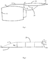
Figs.1-2 , the fairing aerodynamic surface G' of thesuspension 20 generally extends from a start point P close to a leading edge of anengine nacelle 10 towards the rear part of the airplane in the airflow direction, and has an inner side surface and an outer side surface. A rear part of the fairing aerodynamic surface G' at thelower surface 32 of the wing and close to a trailing edge of thewing 30 shrinks to be a line or a surface with a relative small width. As for the airplane with a wing-mounted arrangement, the main difficulty of mounting the engine to the wing in a close range lies in the arrangement of the suspension having certain inner space. In the prior art as shown inFigs.1 and 2 , the fairing aerodynamic surface G' of the suspension extends rewards to the upper surface of the wing at a substantially the same maximum height Hmax after rising to the maximum height position, that is to say, an intersecting point O' between the fairing aerodynamic surface G' and the leadingedge 31 of the wing is located on the upper surface of the wing, which will cause disturbance to thewing 30, specifically the upper surface of the wing, thereby reducing the lift force of the airplane and decreasing the performance of the airplane. Thus, the disturbance to the upper surface of the wing needs to be reduced if the engine is desired to be mounted to the wing in a close range. - A fairing surface which is similar to that description of
Figs. 1 and 2 is disclosed inFR 2 899 201 A1 - For facilitating the description, the fairing aerodynamic surface of the suspension will be abbreviated to "suspension" in the following description.
- The suspension comprises structures needed by suspending the engine of the airplane, and inner systems, electrical cables, seals and structure members that are necessary for maintaining the operation of the engine and the airplane, and these components has a certain requirements for the inner space of the suspension. In order to ensure the inner space of the suspension, the following solutions are generally utilized:
- 1. The distance between the engine and the leading edge of the wing is increased, so that the inner space of the suspension is increased, and thus the suspension is kept under the leading edge of the wing;
- 2. The suspension has a relative large height and extends rearwards to a position above the leading edge of the wing, that is to say, the suspension extends to the upper surface of the wing;
- 3. The suspension is kept below the leading edge of the wing, but the width of the suspension needs to be increased.
- These solutions have both advantages and disadvantages. In the first solution, the length of the landing gear is increased since the distance between the engine and the leading edge of the wing is increased, which will increase the weight and the fuel consumption of the airplane, reduce the payload of the airplane and affect the carrying capacity of the airplane. In the second solution, the height of the landing gear is not increased, thus the disadvantageous influence in the first solution can be avoided, but the flight performance of the airplane is reduced. That is to say, when the suspension extends rearwards to the position above the wing, the suspension will cause a flow separation on the upper surface of the wing in the case of small angle of attack so that the drag force is increased, or causes a flow separation at a large area on the upper surface of the wing in the case of large angle of attack so that the pitching up of the moment happens in advance, which will endanger the safety of the airplane, thus the second solution has a significant influence on the upper surface of the wing. In the third solution, the disadvantages influence caused by increasing the length of the landing gear in the first solution and the disturbance to the upper surface of the wing in the second solution can be avoided, but increasing the width of the suspension can reduce the area of the cross section of the flow-out channel of the engine, which will block the flowing in the engine and reduce the engine thrust, thereby reducing the propulsive efficiency of the engine.
- In order to eliminate or reduce the disadvantageous influence caused by the suspension extending to the position above the wing,
WO8401347A1 US3960345 discloses that a fin is provided to the nacelle surface of the wing, which can suppress the vortex caused by the engine or the suspension extending to the position above the wing, increase the lift force and drag force of the airplane, enhance the stability, and reduce the disadvantageous influence on the airplane due to the downwash.US 3968946A discloses that a movable fairing is provided to fill the gap between the fixed fairing and the leading edge slat when the engine or the suspension extends to the upper surface of the wing. The above solutions disclosed in the above patents overcome the disadvantageous influences due to the suspension extending to the position above the wing by adding an additional device, which may increase the additional weight of the airplane, reduce the airplane payload, and reduce the carrying performance of the airplane. - In order to overcome the above defects existing in the prior art, the present invention provides an airplane suspension fairing structure with a wing-mounted arrangement, which can maintain or enhance the aerodynamic performance of the airplane while mounting the engine to the wing in a close range.
- In the practical engineering, the suspension of the airplane does not need to have a large space everywhere for containing the components such as inner systems, electrical cables, seals and structure members. Actually, the space at some relatively important position needs to be larger than that at other positions. For example, at the interface between a fire area and a non-fire area of the suspension, due to the existence of the firewall, a larger seal assembly therein requires a larger inner space, thus the requirement for a larger inner space only exists at the specific position (for example, the position of the firewall of the suspension). With regard to the above circumstances, the present invention is proposed to overcome the defects in the prior art by improving the airplane suspension fairing structure.
- According to the invention, the present invention provides an airplane suspension fairing structure with a wing-mounted arrangement, the fairing structure comprising a front fairing which is placed in front of a leading edge of a wing and a rear fairing which is placed at the back of the leading edge of the wing, wherein a vertical section line of the front fairing is a curved line and rises to the maximum height position from a start point close to an engine nacelle in the airflow direction and then descends and extends to a position below a lower surface of the wing.
- Advantageously, the maximum height position is the position where the suspension requires a maximum inner space.
- According to the invention, the maximum height position is a first position where is higher than an upper surface of the wing.
- According to the invention, the vertical section line of the front fairing is S-shaped having a curvature that is reversed after descending to a second position from the first position in the airflow direction, descending to a minimum position of the reversed curvature at a third position, and extending to a position below the lower surface of the wing at a fourth position.
- Advantageously, a ratio of a height difference between the first position and the fourth position to a distance between the start point and the fourth position is no more than 0.016.
- Advantageously, a ratio of a distance between the first position and the fourth position to the distance between the start point and the fourth position is no more than 0.3.
- In the present invention, the vertical section line of the front fairing of the suspension is designed to be a curved line, preferably S-shaped, and only at the position (for example, the position close to the firewall) where a relatively large inner space is needed, the height of the fairing is increased to meet the requirement for the inner space of the suspension, thus when the fairing aerodynamic surface of the suspension reaches the leading edge of the wing, the longitudinal height of the suspension is below the leading edge of the wing, so that the engine can be mounted to the wing in a close range, the landing gear of the airplane does not need to be lengthened, and extra devices do not need to be added, thus there is no additional weight. The fairing aerodynamic surface of the suspension cannot extend to the upper surface of the wing, so that the disturbance of the suspension to the wing is avoided during cruising flight. Additionally, the width of the suspension is not increased, thus there is no disadvantageous influence on the engine thrust efficiency. Moreover, the present invention enables the suspension to have necessary arrangement space (enveloping structure and firewall pipe) while maintaining a good flight performance of the airplane.
- Other characteristics and advantages will become apparent from the following description of the invention. In the figures, the same reference signs indicate the same or similar parts, in which:
- Fig. 1
- is a schematic view of an engine and a wing connected by an airplane suspension with a wing-mounted arrangement, illustrating a fairing structure of the airplane suspension in the prior art;
- Fig. 2
- is a schematic view of an aerodynamic surface of a front fairing of a suspension in the prior art;
- Fig. 3
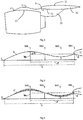
- is a schematic view of an engine and a wing connected by a fairing structure of a suspension according to the present invention;
- Fig. 4
- is a schematic view of an aerodynamic surface of a front fairing of a suspension according to the present invention;
- Fig. 5
- is a view similar to
Fig.4 , illustrating a curvature profile of the aerodynamic surface of the front fairing of the suspension. - The following description will describe an airplane suspension fairing structure with a wing-mounted arrangement. In the following description, some orientation terms, such as "left", "right", "top", "bottom", "front", "back", "guide", "forwards", and "backwards", are used with reference to the directions shown in the drawings, and the orientation terms are used as example rather than limitation. However, it should be appreciated that the described embodiments are only used to illustrate the special form for implementing and applying the present invention in an exemplary manner, rather than limit the scope of the present invention.
- Referring to
Figs. 3 and 4 , according to one preferred embodiment of the present invention, the improving design for a fairing structure of asuspension 20 can be implemented by configuring a vertical section line G of a front fairing of the suspension to be S-shaped. In this way, the front fairing is higher than a leading edge line of the wing, the longitudinal height of thesuspension 20 is gradually reduced in the airflow direction, and the leadingedge 31 maintains a complete wing head, thereby avoiding the influence due to the aerodynamic configuration of thesuspension 20. Additionally, the superficial airflow of thesuspension 20 flows along the surface of the suspension, and thesuspension 20 guides the airflow to flow below the leadingedge 31, thereby effectively reducing or avoiding the disturbance of the superficial airflow of thesuspension 20 to theupper surface 33 of the wing. - Specifically, the vertical section line G of the
suspension 20 starts from a front point P. The vertical section line G rises gradually and reaches a maximum height Hmax at a position where thesuspension 20 needs to have a maximum inner space, that is, the maximum height position of thesuspension 20, i.e., a first position S01 (for example, the location of the firewall). The maximum height Hmax is higher than the leadingedge 31 of the wing. Then, the vertical section line G descends slowly, and a curvature of the vertical section line G is reversed at a second position S02, that is to say, the vertical section line G is transformed to a concave curve from a convex curve. Then, the vertical section line G descends to a minimum position of the convex curve at a third position S03, rises smoothly and contacts the wing and extends below the leadingedge 31 of the wing at a fourth position S04. In this way, the vertical section line G of thesuspension 20 is configured to be S-shaped. The advantage of this configuration lies in that after thesuspension 20 reaches the maximum position, a space is left in the area along the airflow direction so that the height of thesuspension 20 can be restored and transited to gradually extend to the position below the leadingedge 31 of the wing, and finally terminate at thelower surface 32 of the wing. As shown inFigs.3 and 4 , the intersecting point O between the vertical section line G of thesuspension 20 and the leadingedge 31 of the wing is located below the leadingedge 31 of the wing. - The following description will define some parameters and introduce the above preferred embodiments with reference to
Figs. 4 and 5 . - The vertical section line G of the
suspension 20 intersects with thelower surface 32 of the wing at the point O at the fourth position S04. The distance between the front start point P of the vertical section line G of thesuspension 20 and the fourth position S04 is denoted as L. The second position S02 where the curvature is reversed is generally located in front of the point O, and has a distance LR from the point O, that is to say, the distance between the first position S01 and the fourth position S04 of thesuspension 20 is denoted as LR, and the difference between the heights of thesuspension 20 at the first position S01 and at the fourth position S04 is denoted as ΔH. - ΔH/L is defined as a relative height of the
suspension 20, which is a dimensionless number for describing the convex degree of the S-shaped front fairing. In some embodiments, parameter ΔH/L is a value typically no more than 0.016. The meaning of the parameter ΔH/L lies in limiting the height of the convex part of the vertical section line G of thesuspension 20, preventing the generated wake flows being too high and avoiding the disadvantageous influence on the downstream wing. - LR/L is defined as a space recovering factor, which is a dimensionless number. In some embodiments, parameter LR/L is a value typically no more than 0.3. This parameter is used to describe the size of the space of the S-shaped front fairing between the maximum point (i.e., the first position S01) and the position extending to the position below the leading edge of the wing. The meaning of this parameter lies in enabling the
suspension 20 to smoothly restore to the lower surface of the wing from the maximum point, avoiding the disadvantageous pressure gradient, and ensuring the aerodynamic performance of the airplane. -
Fig. 5 also illustrates a schematic curvature profile of the vertical section line G of the front fairing of thesuspension 20. The person skilled in the art can design the size of the curvature of the convex curve and the concave curve respectively depending on the actual requirements, and thereby change the height at the first position S01 and the third position S03 to achieve different space and/or airflow distribution. - The above illustrates and describes basic principles, main features and advantages of the present invention. Those skilled in the art should appreciate that the above embodiments do not limit the present invention in any form. Technical solutions obtained by equivalent substitution or equivalent variations all fall within the scope of the present invention.
Claims (3)
- An airplane suspension (20) fairing structure with a wing-mounted arrangement, in combination with a wing and an engine nacelle (10), the fairing structure connecting the engine nacelle (10) and the wing, the wing having a lower surface (32) and an upper surface (33), the fairing structure comprising a front fairing located in front of the leading edge (31) of the wing and a rear fairing located at the back of the leading edge (31) of the wing, wherein a vertical cross section line (G) of the front fairing is curved, ascending along airflow direction from a start point (P) close to the engine nacelle (10) to a maximum height position and then descending and extending to the lower surface (32) of the wing;
wherein the maximum height position is a first position (S01) which is higher than the leading edge (31) of the wing;
wherein the maximum height position is the position where the airplane suspension (20) requires a maximum inner space;
wherein the vertical cross section line (G) of the front fairing is S-shaped having a curvature that is reversed after descending to a second position (S02) from the first position (S01) in the airflow direction, descending to a minimum position of the reversed curvature at a third position (S03), and extending to the lower surface (32) of the wing at a fourth position (S04). - The airplane suspension (20) fairing structure in combination with the wing and the engine nacelle (10) according to Claim 1, wherein the ratio of the height difference (△H) between the first position (S01) and the fourth position (S04) to the distance (L) between the start point (P) and the fourth position (S04) is no more than 0.016.
- The airplane suspension (20) fairing structure in combination with the wing and the engine nacelle (10) according to Claim 2, wherein the ratio of the distance (LR) between the first position (S01) and the fourth position (S04) to the distance (L) between the start point (P) and the fourth position (S04) is no more than 0.3.
Applications Claiming Priority (2)
| Application Number | Priority Date | Filing Date | Title |
|---|---|---|---|
| CN201310509001.4A CN103612769B (en) | 2013-10-24 | 2013-10-24 | Fairing structure of suspension in wing suspension layout aircraft |
| PCT/CN2014/085418 WO2015058586A1 (en) | 2013-10-24 | 2014-08-28 | Airplane suspension cowling structure with wing-mounted arrangement |
Publications (3)
| Publication Number | Publication Date |
|---|---|
| EP2987728A1 EP2987728A1 (en) | 2016-02-24 |
| EP2987728A4 EP2987728A4 (en) | 2016-12-14 |
| EP2987728B1 true EP2987728B1 (en) | 2018-09-19 |
Family
ID=50163499
Family Applications (1)
| Application Number | Title | Priority Date | Filing Date |
|---|---|---|---|
| EP14855661.6A Active EP2987728B1 (en) | 2013-10-24 | 2014-08-28 | Airplane suspension cowling structure with wing-mounted arrangement |
Country Status (4)
| Country | Link |
|---|---|
| US (1) | US9950803B2 (en) |
| EP (1) | EP2987728B1 (en) |
| CN (1) | CN103612769B (en) |
| WO (1) | WO2015058586A1 (en) |
Families Citing this family (6)
| Publication number | Priority date | Publication date | Assignee | Title |
|---|---|---|---|---|
| CN103612769B (en) | 2013-10-24 | 2016-09-21 | 中国商用飞机有限责任公司 | Fairing structure of suspension in wing suspension layout aircraft |
| FR3064605A1 (en) * | 2017-03-28 | 2018-10-05 | Airbus Operations | METAL FIRE JOINTING SYSTEM FOR AN AIRCRAFT ENGINE ATTACHMENT |
| CN113291457B (en) * | 2021-05-19 | 2023-09-05 | 中航西安飞机工业集团股份有限公司 | Aircraft nose fairing structure and aircraft attitude control method |
| CN114516404B (en) * | 2022-02-14 | 2024-04-09 | 中国商用飞机有限责任公司 | Hanging fairing |
| US12448139B2 (en) * | 2023-01-17 | 2025-10-21 | General Electric Company | Open rotor pylon fairing |
| EP4467462A1 (en) * | 2023-05-19 | 2024-11-27 | Airbus Operations (S.A.S.) | Aircraft fairing comprising a removable panel and a compressible seal, aircraft comprising at least one such fairing |
Citations (1)
| Publication number | Priority date | Publication date | Assignee | Title |
|---|---|---|---|---|
| FR2899201A1 (en) * | 2006-03-31 | 2007-10-05 | Airbus France Sas | Aircraft`s e.g. twin-engine aircraft, wing arrangement, has zone including projection delimiting channel, where air flow is accelerated through channel and is evacuated in direction privileged under wing, between surface of wing and nacelle |
Family Cites Families (15)
| Publication number | Priority date | Publication date | Assignee | Title |
|---|---|---|---|---|
| US3968946A (en) | 1975-03-31 | 1976-07-13 | The Boeing Company | Extendable aerodynamic fairing |
| US3960345A (en) | 1975-05-16 | 1976-06-01 | Grumman Aerospace Corporation | Means to reduce and/or eliminate vortices, caused by wing body combinations |
| US4410150A (en) | 1980-03-03 | 1983-10-18 | General Electric Company | Drag-reducing nacelle |
| US4489905A (en) * | 1981-09-30 | 1984-12-25 | The Boeing Company | Nacelle-pylon configuration for an aircraft and method of using the same |
| DE3279243D1 (en) | 1982-09-30 | 1989-01-05 | Boeing Co | Shock inducing pod for causing flow separation |
| US5524847A (en) * | 1993-09-07 | 1996-06-11 | United Technologies Corporation | Nacelle and mounting arrangement for an aircraft engine |
| FR2734868B1 (en) * | 1995-06-02 | 1997-08-14 | Hurel Dubois Avions | TWO-DOOR PUSH-INVERTER ASSEMBLY |
| FR2903666B1 (en) * | 2006-07-11 | 2008-10-10 | Airbus France Sas | AIRCRAFT ENGINE ASSEMBLY COMPRISING AERODYNAMIC JOINT COVERAGE MOUNTED ON TWO SEPARATE ELEMENTS |
| US20080296432A1 (en) * | 2007-06-04 | 2008-12-04 | Kernkamp Industries Corporation | Method of extending length of aircraft to increase interior space |
| FR2921342B1 (en) | 2007-09-20 | 2010-03-12 | Airbus France | LOWER REAR AERODYNAMIC FAIRING FOR AN AIRCRAFT ENGINE CLAMPING DEVICE |
| US8469309B2 (en) * | 2008-12-24 | 2013-06-25 | General Electric Company | Monolithic structure for mounting aircraft engine |
| US9057286B2 (en) | 2010-03-30 | 2015-06-16 | United Technologies Corporation | Non-circular aft nacelle cowling geometry |
| FR2977237B1 (en) * | 2011-06-28 | 2014-11-21 | Airbus Operations Sas | REAR AERODYNAMIC FAIRING OF A MATERIAL FOR CONNECTING AN AIRCRAFT ENGINE |
| FR2981636B1 (en) * | 2011-10-19 | 2013-12-27 | Airbus Operations Sas | AERODYNAMIC REAR FITTING FOR AN AIRCRAFT ENGINE HANDLING DEVICE, COMPRISING A THERMAL SHIELD CAPABLE OF FREE DILATION |
| CN103612769B (en) * | 2013-10-24 | 2016-09-21 | 中国商用飞机有限责任公司 | Fairing structure of suspension in wing suspension layout aircraft |
-
2013
- 2013-10-24 CN CN201310509001.4A patent/CN103612769B/en active Active
-
2014
- 2014-08-28 US US14/893,717 patent/US9950803B2/en active Active
- 2014-08-28 WO PCT/CN2014/085418 patent/WO2015058586A1/en not_active Ceased
- 2014-08-28 EP EP14855661.6A patent/EP2987728B1/en active Active
Patent Citations (1)
| Publication number | Priority date | Publication date | Assignee | Title |
|---|---|---|---|---|
| FR2899201A1 (en) * | 2006-03-31 | 2007-10-05 | Airbus France Sas | Aircraft`s e.g. twin-engine aircraft, wing arrangement, has zone including projection delimiting channel, where air flow is accelerated through channel and is evacuated in direction privileged under wing, between surface of wing and nacelle |
Also Published As
| Publication number | Publication date |
|---|---|
| CN103612769A (en) | 2014-03-05 |
| WO2015058586A1 (en) | 2015-04-30 |
| US9950803B2 (en) | 2018-04-24 |
| EP2987728A4 (en) | 2016-12-14 |
| EP2987728A1 (en) | 2016-02-24 |
| CN103612769B (en) | 2016-09-21 |
| US20160114897A1 (en) | 2016-04-28 |
Similar Documents
| Publication | Publication Date | Title |
|---|---|---|
| US9950803B2 (en) | Airplane suspension cowling structure with wing-mounted arrangement | |
| US4706910A (en) | Combined riblet and lebu drag reduction system | |
| EP2418148B1 (en) | Aircraft having a lambda-box wing configuration | |
| EP3261923B1 (en) | Airframe-integrated propeller-driven propulsion systems | |
| EP2757039B1 (en) | Fuselage and method for reducing drag | |
| US8186619B2 (en) | Airplane engine pylon comprising at least one protruding element to generate a vortex of the airflow | |
| EP2322419A1 (en) | Wing structure for wig vehicle | |
| EP2490934B1 (en) | Aircraft horizontal stabiliser fitted with leading-edge strake | |
| CA2647762C (en) | Aircraft wing arrangement comprising an engine attachment strut defining in the front zone a lateral air flow channel | |
| US20090261198A1 (en) | Pylon for suspending a turboengine | |
| JP3980775B2 (en) | Aircraft wave resistance reduction method | |
| US20180170508A1 (en) | Lift generating fuselage for aircraft | |
| US6834830B2 (en) | Main wing structure | |
| EP2987721A1 (en) | Nose cone structure for pylon of aircraft with wing-hung layout | |
| EP1371550B1 (en) | Trailing edge shape of laminar-flow airfoil | |
| EP3279082A1 (en) | Aircraft having supporting fuselage | |
| CN102167152B (en) | Leading edge aligned aircraft wingtip device | |
| US20110180672A1 (en) | Airplane with aerodynamic stall-prevention layout and pertinent longitudinal stability arrangement | |
| US20110206528A1 (en) | Wing Structure for WIG Vehicle | |
| CN102167153B (en) | trailing edge aligned aircraft wingtip device | |
| CN102167154B (en) | Wingtip device of airplane | |
| CN102941927B (en) | Axial-symmetry blunt body returner | |
| EP2684797B1 (en) | Airplane wingtip device | |
| EP0120009B1 (en) | Shock inducing pod for causing flow separation | |
| KR102798621B1 (en) | Aircraft and related manufacturing methods |
Legal Events
| Date | Code | Title | Description |
|---|---|---|---|
| PUAI | Public reference made under article 153(3) epc to a published international application that has entered the european phase |
Free format text: ORIGINAL CODE: 0009012 |
|
| 17P | Request for examination filed |
Effective date: 20151119 |
|
| AK | Designated contracting states |
Kind code of ref document: A1 Designated state(s): AL AT BE BG CH CY CZ DE DK EE ES FI FR GB GR HR HU IE IS IT LI LT LU LV MC MK MT NL NO PL PT RO RS SE SI SK SM TR |
|
| AX | Request for extension of the european patent |
Extension state: BA ME |
|
| RIC1 | Information provided on ipc code assigned before grant |
Ipc: B64D 29/02 20060101AFI20161103BHEP Ipc: B64C 7/02 20060101ALI20161103BHEP |
|
| A4 | Supplementary search report drawn up and despatched |
Effective date: 20161114 |
|
| DAX | Request for extension of the european patent (deleted) | ||
| STAA | Information on the status of an ep patent application or granted ep patent |
Free format text: STATUS: EXAMINATION IS IN PROGRESS |
|
| 17Q | First examination report despatched |
Effective date: 20170919 |
|
| RIC1 | Information provided on ipc code assigned before grant |
Ipc: B64C 7/02 20060101ALI20180207BHEP Ipc: B64D 27/26 20060101ALI20180207BHEP Ipc: B64D 29/02 20060101AFI20180207BHEP |
|
| GRAP | Despatch of communication of intention to grant a patent |
Free format text: ORIGINAL CODE: EPIDOSNIGR1 |
|
| STAA | Information on the status of an ep patent application or granted ep patent |
Free format text: STATUS: GRANT OF PATENT IS INTENDED |
|
| INTG | Intention to grant announced |
Effective date: 20180403 |
|
| GRAS | Grant fee paid |
Free format text: ORIGINAL CODE: EPIDOSNIGR3 |
|
| GRAA | (expected) grant |
Free format text: ORIGINAL CODE: 0009210 |
|
| STAA | Information on the status of an ep patent application or granted ep patent |
Free format text: STATUS: THE PATENT HAS BEEN GRANTED |
|
| AK | Designated contracting states |
Kind code of ref document: B1 Designated state(s): AL AT BE BG CH CY CZ DE DK EE ES FI FR GB GR HR HU IE IS IT LI LT LU LV MC MK MT NL NO PL PT RO RS SE SI SK SM TR |
|
| REG | Reference to a national code |
Ref country code: GB Ref legal event code: FG4D |
|
| REG | Reference to a national code |
Ref country code: CH Ref legal event code: EP |
|
| REG | Reference to a national code |
Ref country code: AT Ref legal event code: REF Ref document number: 1042956 Country of ref document: AT Kind code of ref document: T Effective date: 20181015 |
|
| REG | Reference to a national code |
Ref country code: IE Ref legal event code: FG4D |
|
| REG | Reference to a national code |
Ref country code: DE Ref legal event code: R096 Ref document number: 602014032752 Country of ref document: DE |
|
| REG | Reference to a national code |
Ref country code: NL Ref legal event code: MP Effective date: 20180919 |
|
| PG25 | Lapsed in a contracting state [announced via postgrant information from national office to epo] |
Ref country code: SE Free format text: LAPSE BECAUSE OF FAILURE TO SUBMIT A TRANSLATION OF THE DESCRIPTION OR TO PAY THE FEE WITHIN THE PRESCRIBED TIME-LIMIT Effective date: 20180919 Ref country code: GR Free format text: LAPSE BECAUSE OF FAILURE TO SUBMIT A TRANSLATION OF THE DESCRIPTION OR TO PAY THE FEE WITHIN THE PRESCRIBED TIME-LIMIT Effective date: 20181220 Ref country code: FI Free format text: LAPSE BECAUSE OF FAILURE TO SUBMIT A TRANSLATION OF THE DESCRIPTION OR TO PAY THE FEE WITHIN THE PRESCRIBED TIME-LIMIT Effective date: 20180919 Ref country code: RS Free format text: LAPSE BECAUSE OF FAILURE TO SUBMIT A TRANSLATION OF THE DESCRIPTION OR TO PAY THE FEE WITHIN THE PRESCRIBED TIME-LIMIT Effective date: 20180919 Ref country code: LT Free format text: LAPSE BECAUSE OF FAILURE TO SUBMIT A TRANSLATION OF THE DESCRIPTION OR TO PAY THE FEE WITHIN THE PRESCRIBED TIME-LIMIT Effective date: 20180919 Ref country code: BG Free format text: LAPSE BECAUSE OF FAILURE TO SUBMIT A TRANSLATION OF THE DESCRIPTION OR TO PAY THE FEE WITHIN THE PRESCRIBED TIME-LIMIT Effective date: 20181219 Ref country code: NO Free format text: LAPSE BECAUSE OF FAILURE TO SUBMIT A TRANSLATION OF THE DESCRIPTION OR TO PAY THE FEE WITHIN THE PRESCRIBED TIME-LIMIT Effective date: 20181219 |
|
| REG | Reference to a national code |
Ref country code: LT Ref legal event code: MG4D |
|
| PG25 | Lapsed in a contracting state [announced via postgrant information from national office to epo] |
Ref country code: AL Free format text: LAPSE BECAUSE OF FAILURE TO SUBMIT A TRANSLATION OF THE DESCRIPTION OR TO PAY THE FEE WITHIN THE PRESCRIBED TIME-LIMIT Effective date: 20180919 Ref country code: HR Free format text: LAPSE BECAUSE OF FAILURE TO SUBMIT A TRANSLATION OF THE DESCRIPTION OR TO PAY THE FEE WITHIN THE PRESCRIBED TIME-LIMIT Effective date: 20180919 Ref country code: LV Free format text: LAPSE BECAUSE OF FAILURE TO SUBMIT A TRANSLATION OF THE DESCRIPTION OR TO PAY THE FEE WITHIN THE PRESCRIBED TIME-LIMIT Effective date: 20180919 |
|
| REG | Reference to a national code |
Ref country code: AT Ref legal event code: MK05 Ref document number: 1042956 Country of ref document: AT Kind code of ref document: T Effective date: 20180919 |
|
| PG25 | Lapsed in a contracting state [announced via postgrant information from national office to epo] |
Ref country code: NL Free format text: LAPSE BECAUSE OF FAILURE TO SUBMIT A TRANSLATION OF THE DESCRIPTION OR TO PAY THE FEE WITHIN THE PRESCRIBED TIME-LIMIT Effective date: 20180919 Ref country code: AT Free format text: LAPSE BECAUSE OF FAILURE TO SUBMIT A TRANSLATION OF THE DESCRIPTION OR TO PAY THE FEE WITHIN THE PRESCRIBED TIME-LIMIT Effective date: 20180919 Ref country code: EE Free format text: LAPSE BECAUSE OF FAILURE TO SUBMIT A TRANSLATION OF THE DESCRIPTION OR TO PAY THE FEE WITHIN THE PRESCRIBED TIME-LIMIT Effective date: 20180919 Ref country code: IS Free format text: LAPSE BECAUSE OF FAILURE TO SUBMIT A TRANSLATION OF THE DESCRIPTION OR TO PAY THE FEE WITHIN THE PRESCRIBED TIME-LIMIT Effective date: 20190119 Ref country code: PL Free format text: LAPSE BECAUSE OF FAILURE TO SUBMIT A TRANSLATION OF THE DESCRIPTION OR TO PAY THE FEE WITHIN THE PRESCRIBED TIME-LIMIT Effective date: 20180919 Ref country code: ES Free format text: LAPSE BECAUSE OF FAILURE TO SUBMIT A TRANSLATION OF THE DESCRIPTION OR TO PAY THE FEE WITHIN THE PRESCRIBED TIME-LIMIT Effective date: 20180919 Ref country code: RO Free format text: LAPSE BECAUSE OF FAILURE TO SUBMIT A TRANSLATION OF THE DESCRIPTION OR TO PAY THE FEE WITHIN THE PRESCRIBED TIME-LIMIT Effective date: 20180919 Ref country code: CZ Free format text: LAPSE BECAUSE OF FAILURE TO SUBMIT A TRANSLATION OF THE DESCRIPTION OR TO PAY THE FEE WITHIN THE PRESCRIBED TIME-LIMIT Effective date: 20180919 Ref country code: IT Free format text: LAPSE BECAUSE OF FAILURE TO SUBMIT A TRANSLATION OF THE DESCRIPTION OR TO PAY THE FEE WITHIN THE PRESCRIBED TIME-LIMIT Effective date: 20180919 |
|
| PG25 | Lapsed in a contracting state [announced via postgrant information from national office to epo] |
Ref country code: SM Free format text: LAPSE BECAUSE OF FAILURE TO SUBMIT A TRANSLATION OF THE DESCRIPTION OR TO PAY THE FEE WITHIN THE PRESCRIBED TIME-LIMIT Effective date: 20180919 Ref country code: PT Free format text: LAPSE BECAUSE OF FAILURE TO SUBMIT A TRANSLATION OF THE DESCRIPTION OR TO PAY THE FEE WITHIN THE PRESCRIBED TIME-LIMIT Effective date: 20190119 Ref country code: SK Free format text: LAPSE BECAUSE OF FAILURE TO SUBMIT A TRANSLATION OF THE DESCRIPTION OR TO PAY THE FEE WITHIN THE PRESCRIBED TIME-LIMIT Effective date: 20180919 |
|
| REG | Reference to a national code |
Ref country code: DE Ref legal event code: R097 Ref document number: 602014032752 Country of ref document: DE |
|
| PLBE | No opposition filed within time limit |
Free format text: ORIGINAL CODE: 0009261 |
|
| STAA | Information on the status of an ep patent application or granted ep patent |
Free format text: STATUS: NO OPPOSITION FILED WITHIN TIME LIMIT |
|
| PG25 | Lapsed in a contracting state [announced via postgrant information from national office to epo] |
Ref country code: DK Free format text: LAPSE BECAUSE OF FAILURE TO SUBMIT A TRANSLATION OF THE DESCRIPTION OR TO PAY THE FEE WITHIN THE PRESCRIBED TIME-LIMIT Effective date: 20180919 |
|
| 26N | No opposition filed |
Effective date: 20190620 |
|
| PG25 | Lapsed in a contracting state [announced via postgrant information from national office to epo] |
Ref country code: SI Free format text: LAPSE BECAUSE OF FAILURE TO SUBMIT A TRANSLATION OF THE DESCRIPTION OR TO PAY THE FEE WITHIN THE PRESCRIBED TIME-LIMIT Effective date: 20180919 |
|
| PG25 | Lapsed in a contracting state [announced via postgrant information from national office to epo] |
Ref country code: TR Free format text: LAPSE BECAUSE OF FAILURE TO SUBMIT A TRANSLATION OF THE DESCRIPTION OR TO PAY THE FEE WITHIN THE PRESCRIBED TIME-LIMIT Effective date: 20180919 |
|
| PG25 | Lapsed in a contracting state [announced via postgrant information from national office to epo] |
Ref country code: LI Free format text: LAPSE BECAUSE OF NON-PAYMENT OF DUE FEES Effective date: 20190831 Ref country code: MC Free format text: LAPSE BECAUSE OF FAILURE TO SUBMIT A TRANSLATION OF THE DESCRIPTION OR TO PAY THE FEE WITHIN THE PRESCRIBED TIME-LIMIT Effective date: 20180919 Ref country code: LU Free format text: LAPSE BECAUSE OF NON-PAYMENT OF DUE FEES Effective date: 20190828 Ref country code: CH Free format text: LAPSE BECAUSE OF NON-PAYMENT OF DUE FEES Effective date: 20190831 |
|
| REG | Reference to a national code |
Ref country code: BE Ref legal event code: MM Effective date: 20190831 |
|
| PG25 | Lapsed in a contracting state [announced via postgrant information from national office to epo] |
Ref country code: IE Free format text: LAPSE BECAUSE OF NON-PAYMENT OF DUE FEES Effective date: 20190828 |
|
| PG25 | Lapsed in a contracting state [announced via postgrant information from national office to epo] |
Ref country code: BE Free format text: LAPSE BECAUSE OF NON-PAYMENT OF DUE FEES Effective date: 20190831 |
|
| PG25 | Lapsed in a contracting state [announced via postgrant information from national office to epo] |
Ref country code: CY Free format text: LAPSE BECAUSE OF FAILURE TO SUBMIT A TRANSLATION OF THE DESCRIPTION OR TO PAY THE FEE WITHIN THE PRESCRIBED TIME-LIMIT Effective date: 20180919 |
|
| PG25 | Lapsed in a contracting state [announced via postgrant information from national office to epo] |
Ref country code: HU Free format text: LAPSE BECAUSE OF FAILURE TO SUBMIT A TRANSLATION OF THE DESCRIPTION OR TO PAY THE FEE WITHIN THE PRESCRIBED TIME-LIMIT; INVALID AB INITIO Effective date: 20140828 Ref country code: MT Free format text: LAPSE BECAUSE OF FAILURE TO SUBMIT A TRANSLATION OF THE DESCRIPTION OR TO PAY THE FEE WITHIN THE PRESCRIBED TIME-LIMIT Effective date: 20180919 |
|
| PG25 | Lapsed in a contracting state [announced via postgrant information from national office to epo] |
Ref country code: MK Free format text: LAPSE BECAUSE OF FAILURE TO SUBMIT A TRANSLATION OF THE DESCRIPTION OR TO PAY THE FEE WITHIN THE PRESCRIBED TIME-LIMIT Effective date: 20180919 |
|
| PGFP | Annual fee paid to national office [announced via postgrant information from national office to epo] |
Ref country code: DE Payment date: 20250819 Year of fee payment: 12 |
|
| PGFP | Annual fee paid to national office [announced via postgrant information from national office to epo] |
Ref country code: GB Payment date: 20250722 Year of fee payment: 12 |
|
| PGFP | Annual fee paid to national office [announced via postgrant information from national office to epo] |
Ref country code: FR Payment date: 20250722 Year of fee payment: 12 |