EP2987698A1 - Vehicle control device for electric rolling stock - Google Patents
Vehicle control device for electric rolling stock Download PDFInfo
- Publication number
- EP2987698A1 EP2987698A1 EP13882445.3A EP13882445A EP2987698A1 EP 2987698 A1 EP2987698 A1 EP 2987698A1 EP 13882445 A EP13882445 A EP 13882445A EP 2987698 A1 EP2987698 A1 EP 2987698A1
- Authority
- EP
- European Patent Office
- Prior art keywords
- width
- hole
- control device
- vehicle control
- pair
- Prior art date
- Legal status (The legal status is an assumption and is not a legal conclusion. Google has not performed a legal analysis and makes no representation as to the accuracy of the status listed.)
- Granted
Links
Images


Classifications
-
- H—ELECTRICITY
- H05—ELECTRIC TECHNIQUES NOT OTHERWISE PROVIDED FOR
- H05K—PRINTED CIRCUITS; CASINGS OR CONSTRUCTIONAL DETAILS OF ELECTRIC APPARATUS; MANUFACTURE OF ASSEMBLAGES OF ELECTRICAL COMPONENTS
- H05K5/00—Casings, cabinets or drawers for electric apparatus
- H05K5/06—Hermetically-sealed casings
- H05K5/069—Other details of the casing, e.g. wall structure, passage for a connector, a cable, a shaft
-
- B—PERFORMING OPERATIONS; TRANSPORTING
- B60—VEHICLES IN GENERAL
- B60R—VEHICLES, VEHICLE FITTINGS, OR VEHICLE PARTS, NOT OTHERWISE PROVIDED FOR
- B60R16/00—Electric or fluid circuits specially adapted for vehicles and not otherwise provided for; Arrangement of elements of electric or fluid circuits specially adapted for vehicles and not otherwise provided for
- B60R16/02—Electric or fluid circuits specially adapted for vehicles and not otherwise provided for; Arrangement of elements of electric or fluid circuits specially adapted for vehicles and not otherwise provided for electric constitutive elements
- B60R16/023—Electric or fluid circuits specially adapted for vehicles and not otherwise provided for; Arrangement of elements of electric or fluid circuits specially adapted for vehicles and not otherwise provided for electric constitutive elements for transmission of signals between vehicle parts or subsystems
- B60R16/0239—Electronic boxes
-
- B—PERFORMING OPERATIONS; TRANSPORTING
- B61—RAILWAYS
- B61C—LOCOMOTIVES; MOTOR RAILCARS
- B61C17/00—Arrangement or disposition of parts; Details or accessories not otherwise provided for; Use of control gear and control systems
-
- H—ELECTRICITY
- H05—ELECTRIC TECHNIQUES NOT OTHERWISE PROVIDED FOR
- H05K—PRINTED CIRCUITS; CASINGS OR CONSTRUCTIONAL DETAILS OF ELECTRIC APPARATUS; MANUFACTURE OF ASSEMBLAGES OF ELECTRICAL COMPONENTS
- H05K5/00—Casings, cabinets or drawers for electric apparatus
- H05K5/02—Details
- H05K5/0204—Mounting supporting structures on the outside of casings
-
- H—ELECTRICITY
- H05—ELECTRIC TECHNIQUES NOT OTHERWISE PROVIDED FOR
- H05K—PRINTED CIRCUITS; CASINGS OR CONSTRUCTIONAL DETAILS OF ELECTRIC APPARATUS; MANUFACTURE OF ASSEMBLAGES OF ELECTRICAL COMPONENTS
- H05K5/00—Casings, cabinets or drawers for electric apparatus
- H05K5/02—Details
- H05K5/0213—Venting apertures; Constructional details thereof
- H05K5/0214—Venting apertures; Constructional details thereof with means preventing penetration of rain water or dust
-
- H—ELECTRICITY
- H05—ELECTRIC TECHNIQUES NOT OTHERWISE PROVIDED FOR
- H05K—PRINTED CIRCUITS; CASINGS OR CONSTRUCTIONAL DETAILS OF ELECTRIC APPARATUS; MANUFACTURE OF ASSEMBLAGES OF ELECTRICAL COMPONENTS
- H05K5/00—Casings, cabinets or drawers for electric apparatus
- H05K5/02—Details
- H05K5/0217—Mechanical details of casings
-
- H—ELECTRICITY
- H05—ELECTRIC TECHNIQUES NOT OTHERWISE PROVIDED FOR
- H05K—PRINTED CIRCUITS; CASINGS OR CONSTRUCTIONAL DETAILS OF ELECTRIC APPARATUS; MANUFACTURE OF ASSEMBLAGES OF ELECTRICAL COMPONENTS
- H05K7/00—Constructional details common to different types of electric apparatus
- H05K7/14—Mounting supporting structure in casing or on frame or rack
- H05K7/1422—Printed circuit boards receptacles, e.g. stacked structures, electronic circuit modules or box like frames
- H05K7/1427—Housings
- H05K7/1432—Housings specially adapted for power drive units or power converters
- H05K7/14325—Housings specially adapted for power drive units or power converters for cabinets or racks
Definitions
- the present disclosure relates to a vehicle control device for electric rolling stock provided with a draining member.
- a control device provided under the floor of a railway vehicle needs to be airtight in order to prevent infiltration of dust and rainwater from the outside.
- the vehicle control device disclosed in Patent Literature 1 is housed inside a vehicle control equipment casing having an opening in the ceiling, and the opening of the vehicle control equipment casing is connected to an opening in the bottom surface of a sealed room provided on the undersurface of the vehicle's framework.
- the railway vehicle control device disclosed in Patent Literature 2 includes inside the device a mechanism having a heat-radiating function while preventing infiltration of rainwater, and has a structure such that the mechanism containing a dividing protrusion (watertight weir) provided in the opening for preventing infiltration of rainwater does not protrude to the outside.
- the vehicle control device for electric rolling stock according to the present disclosure mounted on electric rolling stock and for controlling the electric rolling stock includes a housing with a through-hole formed in the bottom surface; and a draining member that is inserted into the through-hole and is held in a state protruding from both openings of the through-hole.
- FIG. 1 is a cross-sectional view of a vehicle control device for electric rolling stock provided with a draining member according to an embodiment of the present disclosure.
- the draining member 1 is inserted from the outside of a housing, for example, into a through-hole formed in a vehicle control device 2 for electric rolling stock (hereafter referred to simply as the vehicle control device), and is held in a state protruding from both openings of the through-hole.
- the top side is the inside of the housing of the vehicle control device 2 and the bottom side is the outside of the housing of the vehicle control device 2.
- the vehicle control device 2 is mounted on electric rolling stock and controls the electric rolling stock.
- FIG. 2 is a frontal view of the draining member according to the embodiment.
- FIG. 3 is a frontal view of the draining member according to the embodiment in a state in which pressure is applied in a direction closing an increased width portion.
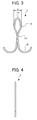
- FIG. 4 is a side view of the draining member according to the embodiment.
- the draining member 1 is formed of a pair of elastic members extending separately from a connecting location, mutually connected (hereafter referred to as the connecting location) 11 and facing each other across a space.
- the draining member 1 may be formed by bending an elastic member such as a single stainless steel wire and/or the like, or may be formed by connecting one end of a pair of elastic members through welding and/or the like.
- the material of which the draining member 1 is formed is not limited to stainless steel, and may be metal such as aluminum, copper, iron and/or the like, or may be resin.
- a width c of the connecting location 11 is smaller than a width b of the through-hole, and the width between the pair of elastic members facing each other is varied from the connecting location 11 toward the ends of the elastic members, reaching a narrow portion 13 smaller than the width b of the through-hole after passing an increased width portion 12 greater than the width b of the through-hole. That is to say, the width a of the increased width portion 12 is greater than the width b of the through-hole, and the width d of the narrow portion 13 is smaller than the width b of the through-hole.
- a leg portion 14 beyond the narrow portion 13 of the pair of elastic members facing each other has a maximum width e greater than the width b of the through-hole.
- the draining member 1 is made of elastic members, and consequently deforms as illustrated in FIG. 3 when pressure is applied in a direction closing the increased width portion 12.
- the pair of elastic members of the leg portion 14 is each bent in a direction separating from the center of the width of the pair of elastic members facing each other.
- the width of the increased width portion 12 becomes a', where a' is less than the width b of the through-hole. That is to say, when pressure of at least a threshold value is applied in a direction closing the increased width portion 12 of the draining member 1, the width a' of the increased width portion 12 is smaller than the width b of the through-hole, so it is possible to insert the draining member 1 into the through-hole from the outside of the housing of the vehicle control device 2.
- the draining member 1 being held does not indicate that the draining member 1 is in a state in which the draining member 1 strictly does not move, but rather means that the draining member 1 does not fall out of the through-hole due to vibrations and/or the like generated while the vehicle is moving, for example.
- the draining member 1 By simply forming through-holes in the housing of the vehicle control device 2, there are cases in which water does not drain due to the water's surface tension, but by the draining member 1 being held in a state protruding from both openings of the through-hole, it is possible to more efficiently drain the inside of the housing of the vehicle control device 2.
- the minimum distance between two locations; one in which the width of the pair of elastic members facing each other between the increased width portion 12 and the narrow portion 13 matches the width of the through-hole, and the other in which the width of the pair of elastic members of the leg portion 14 facing each other is equal to or greater than the width of the through-hole, is at least a threshold value that is greater than the thickness of the housing of the vehicle control device 2.
- a distance g between the location where the width of the pair of elastic members facing each other between the increased width portion 12 and the narrow portion 13 matches the width b of the through-hole and the location where the width of the pair of elastic members facing each other is a maximum in the leg portion 14 is the above-described minimum distance.
- the above-described minimum distance g is equal to or greater than a threshold value greater than a thickness f of the housing of the vehicle control device 2, it is possible for draining of the inside of the housing of the vehicle control device 2 to be accomplished more efficiently because the draining member 1 vibrates in the direction of insertion into the housing of the vehicle control device 2 due to vibrations generated while the vehicle is moving, for example.
- the threshold value can be freely-determined in the light of draining efficiency.
- FIG. 5 is a cross-sectional view of the vehicle control device for electric rolling stock provided with the draining member according to the embodiment.
- the shape of the leg portion 14 differs from that of the draining member 1 illustrated in FIG. 1 .
- a distance g' between a location where the width of the pair of elastic members facing each other between the increased width portion 12 and the narrow portion 13 matches the width b of the through-hole and a location where the width of the pair of elastic members facing each other in the leg portion 14 matches the width b of the through-hole is the above-described minimum distance.
- FIG. 6 is a cross-sectional view along the railroad tie direction of a vehicle provided with the control device for electric rolling stock according to the embodiment.
- Through-holes are formed in the bottom surface of the vehicle control device 2, and each of the draining members 1 is inserted into each of the through-holes and held in place.
- the vehicle control device 2 is attached to the bottom side of a framework 4 of a vehicle 3.
- the size of the vehicle control device 2, the number of through-holes, the surface where the through-holes are formed and the method of attachment to the vehicle 3 are arbitrary and not limited to the example illustrated in FIG. 6 .
- FIG. 7 is an oblique view of the vehicle control device for electric rolling stock according to the embodiment. Dashed-dotted lines indicate compartments inside the vehicle control device 2. As indicated by black dots in FIG. 7 , at least one through-hole is formed in each compartmentalized space in the bottom surface of the vehicle control device 2.
- the position and number of through-holes can be freely-determined in accordance with the area of the compartmentalized bottom surface and the necessity of airtightness of the vehicle control device 2. For example, it would be fine to form through-holes in four corners or two corners of the bottom surface. When through-holes are formed in four corners or two corners, it is possible to drain water more efficiently in accordance with the gradient of the railway track of the vehicle.
- through-holes 4 mm in diameter may be formed in the four corners of the bottom surface of the vehicle control device 2.
- FIG. 8 is an oblique view of the vehicle control device for electric rolling stock according to the embodiment. Dashed-dotted lines indicate compartments inside the vehicle control device 2, and black dots indicate through-holes.
- a frame 5 is connected to the outside of the housing surface where the through-holes are formed.
- the length in the insertion direction of the portion protruding to the outside of the housing of the vehicle control device 2 is shorter than the length of the frame 5 in the insertion direction. That is to say, of the draining members 1 illustrated in FIG.
- the length h in the insertion direction of the portion protruding to the outside of the housing of the vehicle control device 2 is shorter than the length i in the insertion direction of the frame 5 illustrated in FIG. 8 . Consequently, even if the vehicle control device 2 is placed on the ground, the draining members 1 do not penetrate any further into the inside of the housing of the vehicle control device 2.
- the shape of the frame 5 is arbitrary and is not limited to the example of FIG. 8 .
- FIG. 9 is a frontal view illustrating a different example of a draining member according to the embodiment.
- the pair of elastic members of the leg portion 14 of the draining member 1 illustrated in FIG. 9 is bent in a U-shape in a direction separating from the center of the width where the two face each other. By bending this portion into a U-shape, it is possible to prevent injuries to fingers when inserting the draining member 1 into a through-hole by applying a force is equal to or greater than a threshold value in the direction for closing the increased width portion 12 for example by pinching the leg portion 14.
- FIG. 10 is a frontal view illustrating a different example of a draining member according to the embodiment.
- a portion of each of the pair of elastic members of the leg portion 14 of the draining member 1 illustrated in FIG. 10 is bent into an arc centered on a point where the distance from the connecting location 11 is large compared to the above-described portion.
- the points in which the width of the pair of elastic members facing each other is equal to or greater than the width of the through-hole, and distance from portions in which the width of the pair of elastic members facing each other between the increased width portion 12 and the narrow portion 13 matches the width of the through-hole is a minimum are positioned at the location bent into the above-described arc shape.
- FIG. 10 because a portion of the draining member 1 that contacts the housing of the vehicle control device 2 when the draining member 1 vibrates in the insertion direction is bent into an arc shape, it is possible to prevent damage to the housing of the vehicle control device 2.
- the draining member 1 according to the embodiment may be inserted into the inside of the housing from the outside of the housing by applying a force of at least a threshold value in the direction for closing the increased width portion 12, so that it is possible to shorten work time when doing the insertion.
- the work of putting in and taking out the draining member 1 according to the embodiment is accomplished from outside of the housing, so it is possible to prevent the draining member 1 from entering the inside of the housing or the draining member 1 being left behind inside the housing when removal work is done.
- the shape of the draining member 1 is not limited to the shapes disclosed in FIG. 2 , FIG. 9 and FIG. 10 .
- the shape of the draining member 1 needs not have left-right symmetry.
- the thickness of the elastic members may be freely-determined in the light of draining efficiency based on the surface area of the through-holes.
- the present disclosure is suitably utilized in an apparatus provided with a draining member and through-holes for draining.
Landscapes
- Engineering & Computer Science (AREA)
- Microelectronics & Electronic Packaging (AREA)
- Mechanical Engineering (AREA)
- Automation & Control Theory (AREA)
- Transportation (AREA)
- Casings For Electric Apparatus (AREA)
- Electric Propulsion And Braking For Vehicles (AREA)
- Current-Collector Devices For Electrically Propelled Vehicles (AREA)
Abstract
Description
- The present disclosure relates to a vehicle control device for electric rolling stock provided with a draining member.
- A control device provided under the floor of a railway vehicle needs to be airtight in order to prevent infiltration of dust and rainwater from the outside.
- The vehicle control device disclosed in Patent Literature 1 is housed inside a vehicle control equipment casing having an opening in the ceiling, and the opening of the vehicle control equipment casing is connected to an opening in the bottom surface of a sealed room provided on the undersurface of the vehicle's framework. The railway vehicle control device disclosed in
Patent Literature 2 includes inside the device a mechanism having a heat-radiating function while preventing infiltration of rainwater, and has a structure such that the mechanism containing a dividing protrusion (watertight weir) provided in the opening for preventing infiltration of rainwater does not protrude to the outside. -
- Patent Literature 1: Unexamined
Japanese Patent Application Kokai Publication No. 2000-258513 - Patent Literature 2: Unexamined
Japanese Patent Application Kokai Publication No. 2007-017357 - When water enters the inside of the housing of the control device due to deterioration of the packing and/or the like, for example, draining of the inside of the housing of the control device becomes necessary. With the art disclosed in
Patent Literature 1 andPatent Literature 2, it is impossible to accomplish draining of the inside of the housing of the control device while the vehicle is moving, for example. - In consideration of the foregoing, it is an objective of the present disclosure to improve draining efficiency.
- In order to accomplish the above objective, the vehicle control device for electric rolling stock according to the present disclosure mounted on electric rolling stock and for controlling the electric rolling stock includes a housing with a through-hole formed in the bottom surface; and a draining member that is inserted into the through-hole and is held in a state protruding from both openings of the through-hole.
- With the present disclosure, it is possible to improve draining efficiency.
-
-
FIG. 1 is a cross-sectional view of a vehicle control device for electric rolling stock provided with a draining member according to an embodiment of the present disclosure; -
FIG. 2 is a frontal view of the draining member according to the embodiment; -
FIG. 3 is a frontal view of the draining member according to the embodiment in a state in which pressure is applied in a direction closing an increased width portion; -
FIG. 4 is a side view of the draining member according to the embodiment; -
FIG. 5 is a cross-sectional view of the vehicle control device for electric rolling stock provided with the draining member according to the embodiment; -
FIG. 6 is a cross-sectional view along the railroad tie direction of a vehicle provided with the vehicle control device for electric rolling stock according to the embodiment; -
FIG. 7 is an oblique view of the vehicle control device for electric rolling stock according to the embodiment; -
FIG. 8 is an oblique view of the vehicle control device for electric rolling stock according to the embodiment; -
FIG. 9 is a frontal view illustrating a different example of the draining member according to the embodiment; and -
FIG. 10 is a frontal view illustrating a different example of the draining member according to the embodiment. - Below, embodiments of the present disclosure are described in detail with reference to the drawings. In the drawings, portions that are the same or equivalent are labeled with the same reference symbols.
-
FIG. 1 is a cross-sectional view of a vehicle control device for electric rolling stock provided with a draining member according to an embodiment of the present disclosure. The drainingmember 1 is inserted from the outside of a housing, for example, into a through-hole formed in avehicle control device 2 for electric rolling stock (hereafter referred to simply as the vehicle control device), and is held in a state protruding from both openings of the through-hole. InFIG. 1 , the top side is the inside of the housing of thevehicle control device 2 and the bottom side is the outside of the housing of thevehicle control device 2. Thevehicle control device 2 is mounted on electric rolling stock and controls the electric rolling stock.FIG. 2 is a frontal view of the draining member according to the embodiment.FIG. 3 is a frontal view of the draining member according to the embodiment in a state in which pressure is applied in a direction closing an increased width portion.FIG. 4 is a side view of the draining member according to the embodiment. - The draining
member 1 is formed of a pair of elastic members extending separately from a connecting location, mutually connected (hereafter referred to as the connecting location) 11 and facing each other across a space. The drainingmember 1 may be formed by bending an elastic member such as a single stainless steel wire and/or the like, or may be formed by connecting one end of a pair of elastic members through welding and/or the like. The material of which thedraining member 1 is formed is not limited to stainless steel, and may be metal such as aluminum, copper, iron and/or the like, or may be resin. - In a state in which no force other than gravity is applied to the draining
member 1, a width c of the connectinglocation 11 is smaller than a width b of the through-hole, and the width between the pair of elastic members facing each other is varied from the connectinglocation 11 toward the ends of the elastic members, reaching anarrow portion 13 smaller than the width b of the through-hole after passing an increasedwidth portion 12 greater than the width b of the through-hole. That is to say, the width a of the increasedwidth portion 12 is greater than the width b of the through-hole, and the width d of thenarrow portion 13 is smaller than the width b of the through-hole. Aleg portion 14 beyond thenarrow portion 13 of the pair of elastic members facing each other has a maximum width e greater than the width b of the through-hole. The drainingmember 1 is made of elastic members, and consequently deforms as illustrated inFIG. 3 when pressure is applied in a direction closing the increasedwidth portion 12. In the examples illustrated inFIGS. 2 and3 , the pair of elastic members of theleg portion 14 is each bent in a direction separating from the center of the width of the pair of elastic members facing each other. - As illustrated in
FIG. 3 , when pressure of at least a threshold value is applied in a direction closing the increasedwidth portion 12 of the drainingmember 1, the width of the increasedwidth portion 12 becomes a', where a' is less than the width b of the through-hole. That is to say, when pressure of at least a threshold value is applied in a direction closing the increasedwidth portion 12 of the drainingmember 1, the width a' of the increasedwidth portion 12 is smaller than the width b of the through-hole, so it is possible to insert the drainingmember 1 into the through-hole from the outside of the housing of thevehicle control device 2. When pressure is no longer applied in the direction for closing the increasedwidth portion 12 with the drainingmember 1 in a state protruding from both openings of the through-hole, the drainingmember 1 is held in a state protruding from both openings of the through-hole, as illustrated inFIG. 1 . - In this embodiment, the
draining member 1 being held does not indicate that thedraining member 1 is in a state in which thedraining member 1 strictly does not move, but rather means that thedraining member 1 does not fall out of the through-hole due to vibrations and/or the like generated while the vehicle is moving, for example. By simply forming through-holes in the housing of thevehicle control device 2, there are cases in which water does not drain due to the water's surface tension, but by the drainingmember 1 being held in a state protruding from both openings of the through-hole, it is possible to more efficiently drain the inside of the housing of thevehicle control device 2. - In the draining
member 1, the minimum distance between two locations; one in which the width of the pair of elastic members facing each other between the increasedwidth portion 12 and thenarrow portion 13 matches the width of the through-hole, and the other in which the width of the pair of elastic members of theleg portion 14 facing each other is equal to or greater than the width of the through-hole, is at least a threshold value that is greater than the thickness of the housing of thevehicle control device 2. In the example inFIG. 1 , a distance g between the location where the width of the pair of elastic members facing each other between the increasedwidth portion 12 and thenarrow portion 13 matches the width b of the through-hole and the location where the width of the pair of elastic members facing each other is a maximum in theleg portion 14 is the above-described minimum distance. By making the above-described minimum distance g is equal to or greater than a threshold value greater than a thickness f of the housing of thevehicle control device 2, it is possible for draining of the inside of the housing of thevehicle control device 2 to be accomplished more efficiently because the drainingmember 1 vibrates in the direction of insertion into the housing of thevehicle control device 2 due to vibrations generated while the vehicle is moving, for example. The threshold value can be freely-determined in the light of draining efficiency. -
FIG. 5 is a cross-sectional view of the vehicle control device for electric rolling stock provided with the draining member according to the embodiment. In the drainingmember 1 illustrated inFIG. 5 , the shape of theleg portion 14 differs from that of thedraining member 1 illustrated inFIG. 1 . In the example inFIG. 5 , a distance g' between a location where the width of the pair of elastic members facing each other between the increasedwidth portion 12 and thenarrow portion 13 matches the width b of the through-hole and a location where the width of the pair of elastic members facing each other in theleg portion 14 matches the width b of the through-hole is the above-described minimum distance. By making the above-described minimum distance g' is equal to or greater than a threshold value greater than the thickness f of the housing of thevehicle control device 2, similarly to the above-described case, it is possible for draining of the inside of the housing of thevehicle control device 2 to be accomplished more efficiently. -
FIG. 6 is a cross-sectional view along the railroad tie direction of a vehicle provided with the control device for electric rolling stock according to the embodiment. Through-holes are formed in the bottom surface of thevehicle control device 2, and each of the drainingmembers 1 is inserted into each of the through-holes and held in place. Thevehicle control device 2 is attached to the bottom side of aframework 4 of avehicle 3. The size of thevehicle control device 2, the number of through-holes, the surface where the through-holes are formed and the method of attachment to thevehicle 3 are arbitrary and not limited to the example illustrated inFIG. 6 . -
FIG. 7 is an oblique view of the vehicle control device for electric rolling stock according to the embodiment. Dashed-dotted lines indicate compartments inside thevehicle control device 2. As indicated by black dots inFIG. 7 , at least one through-hole is formed in each compartmentalized space in the bottom surface of thevehicle control device 2. The position and number of through-holes can be freely-determined in accordance with the area of the compartmentalized bottom surface and the necessity of airtightness of thevehicle control device 2. For example, it would be fine to form through-holes in four corners or two corners of the bottom surface. When through-holes are formed in four corners or two corners, it is possible to drain water more efficiently in accordance with the gradient of the railway track of the vehicle. In addition, it would be fine to make an incline in the bottom surface of thevehicle control device 2 and to form through-holes in a location on the bottom side of the incline. The shape of the through-holes is arbitrary, and is determined in the light of draining efficiency and the airtightness of thevehicle control device 2. For example, through-holes 4 mm in diameter may be formed in the four corners of the bottom surface of thevehicle control device 2. -
FIG. 8 is an oblique view of the vehicle control device for electric rolling stock according to the embodiment. Dashed-dotted lines indicate compartments inside thevehicle control device 2, and black dots indicate through-holes. In the housing of thevehicle control device 2, aframe 5 is connected to the outside of the housing surface where the through-holes are formed. Of the drainingmembers 1 inserted into and held in the through-holes in thevehicle control device 2 illustrated inFIG. 8 , the length in the insertion direction of the portion protruding to the outside of the housing of thevehicle control device 2 is shorter than the length of theframe 5 in the insertion direction. That is to say, of the drainingmembers 1 illustrated inFIG. 1 , the length h in the insertion direction of the portion protruding to the outside of the housing of thevehicle control device 2 is shorter than the length i in the insertion direction of theframe 5 illustrated inFIG. 8 . Consequently, even if thevehicle control device 2 is placed on the ground, the drainingmembers 1 do not penetrate any further into the inside of the housing of thevehicle control device 2. The shape of theframe 5 is arbitrary and is not limited to the example ofFIG. 8 . -
FIG. 9 is a frontal view illustrating a different example of a draining member according to the embodiment. The pair of elastic members of theleg portion 14 of the drainingmember 1 illustrated inFIG. 9 is bent in a U-shape in a direction separating from the center of the width where the two face each other. By bending this portion into a U-shape, it is possible to prevent injuries to fingers when inserting the drainingmember 1 into a through-hole by applying a force is equal to or greater than a threshold value in the direction for closing the increasedwidth portion 12 for example by pinching theleg portion 14. -
FIG. 10 is a frontal view illustrating a different example of a draining member according to the embodiment. A portion of each of the pair of elastic members of theleg portion 14 of the drainingmember 1 illustrated inFIG. 10 is bent into an arc centered on a point where the distance from the connectinglocation 11 is large compared to the above-described portion. In theleg portion 14, the points in which the width of the pair of elastic members facing each other is equal to or greater than the width of the through-hole, and distance from portions in which the width of the pair of elastic members facing each other between the increasedwidth portion 12 and thenarrow portion 13 matches the width of the through-hole is a minimum are positioned at the location bent into the above-described arc shape. As illustrated inFIG. 10 , because a portion of the drainingmember 1 that contacts the housing of thevehicle control device 2 when the drainingmember 1 vibrates in the insertion direction is bent into an arc shape, it is possible to prevent damage to the housing of thevehicle control device 2. - For example, when a cotter pin is used as the draining member, in order for the cotter pin to be inserted into and held in a through-hole formed in the housing, it is necessary for the leg parts of the cotter pin to be inserted first from inside the housing, causing the cotter pin to protrude from both openings of the through-hole, and for the leg parts of the cotter pin to be bent in different directions from the outside of the housing. In addition, the work of bending the leg parts of the cotter pin is painstaking work using pliers and requires time. In contrast, the draining
member 1 according to the embodiment may be inserted into the inside of the housing from the outside of the housing by applying a force of at least a threshold value in the direction for closing the increasedwidth portion 12, so that it is possible to shorten work time when doing the insertion. In addition, the work of putting in and taking out the drainingmember 1 according to the embodiment is accomplished from outside of the housing, so it is possible to prevent the drainingmember 1 from entering the inside of the housing or the drainingmember 1 being left behind inside the housing when removal work is done. - The shape of the draining
member 1 is not limited to the shapes disclosed inFIG. 2 ,FIG. 9 and FIG. 10 . The shape of the drainingmember 1 needs not have left-right symmetry. The thickness of the elastic members may be freely-determined in the light of draining efficiency based on the surface area of the through-holes. - As explained above, with the
vehicle control device 2 provided with the drainingmember 1 according to the embodiment of the present disclosure, it is possible to improve draining efficiency. - The foregoing describes some example embodiments for explanatory purposes. Although the foregoing discussion has presented specific embodiments, persons skilled in the art will recognize that changes may be made in form and detail without departing from the broader spirit and scope of the invention. Accordingly, the specification and drawings are to be regarded in an illustrative rather than a restrictive sense. This detailed description, therefore, is not to be taken in a limiting sense, and the scope of the invention is defined only by the included claims, along with the full range of equivalents to which such claims are entitled.
- The present disclosure is suitably utilized in an apparatus provided with a draining member and through-holes for draining.
-
- 1
- Draining member
- 2
- Vehicle control device for electric rolling stock
- 3
- Vehicle
- 4
- Framework
- 5
- Frame
- 11
- Connecting location
- 12
- Increased width portion
- 13
- Narrow portion
- 14
- Leg portion
Claims (7)
- A vehicle control device for electric rolling stock mounted on the electric rolling stock and for controlling the electric rolling stock, the vehicle control device comprising:a housing with a through-hole formed in the bottom surface thereof; anda draining member that is inserted into the through-hole and is held in a state protruding from both openings of the through-hole.
- The vehicle control device for electric rolling stock according to Claim 1, wherein:the draining member is formed of a pair of elastic members extending separately from a connecting location, mutually connected, and facing each other across a space;the connecting location has a width smaller than a width of the through-hole, and the width between the pair of elastic members facing each other is varied from the connecting location toward the ends of the elastic members, reaching a narrow portion of which the width is smaller than the width of the through-hole via an increased width portion of which the width is greater than the width of the through-hole, and a leg portion beyond the narrow portion have a maximum width of the pair of elastic members facing each other that is greater than the width of the through-hole;a minimum distance between two locations; one in which the width of the pair of elastic member facing each other between the increased width portion and the narrow portion matches the width of the through-hole, and the other in which the width of the pair of elastic members of the leg portion facing each other is equal to or greater than the width of the through-hole, is equal to or greater than a threshold value that is greater than a thickness of the housing; andwhen a pressure equal to or greater than a threshold value is applied in a direction for closing the increased width portion, the width of the increased width portion becomes smaller than the width of the through-hole.
- The vehicle control device for electric rolling stock according to Claim 2, wherein each of the pair of elastic members of the leg portion is bent in a direction separating from the center of the width where the pair face each other.
- The vehicle control device for electric rolling stock according to Claim 2, wherein each of the pair of elastic members of the leg portion is bent in into a U-shape in a direction separating from the center of the width where the pair face each other.
- The vehicle control device for electric rolling stock according to Claim 2, wherein a portion of each of the pair of elastic members of the leg portion is bent in an arc shape centered on a point where the distance from the connecting location is greater than the distance between the portion and the connecting location, and in the leg portion, the points in which the width of the pair of elastic members facing each other is equal to or greater than the width of the through-hole, and distance from portions in which the width of the pair of elastic members facing each other between the increased width portion and the narrow portion matches the width of the through-hole is a minimum are positioned at the location bent into the arc shape.
- The vehicle control device for electric rolling stock according to Claim 1, further comprising a frame connected to the outside of the surface in which the through-hole is formed;
wherein in the draining member, the length in the insertion direction of the portion protruding to the outside of the housing is shorter than a length in the insertion direction of the frame. - The vehicle control device for electric rolling stock according to Claim 1, wherein:the housing includes compartments dividing the space inside; andat least one through-hole is formed in the bottom surface of the spaces divided by the compartments.
Applications Claiming Priority (1)
| Application Number | Priority Date | Filing Date | Title |
|---|---|---|---|
| PCT/JP2013/061447 WO2014170980A1 (en) | 2013-04-18 | 2013-04-18 | Vehicle control device for electric rolling stock |
Publications (3)
| Publication Number | Publication Date |
|---|---|
| EP2987698A1 true EP2987698A1 (en) | 2016-02-24 |
| EP2987698A4 EP2987698A4 (en) | 2016-11-16 |
| EP2987698B1 EP2987698B1 (en) | 2018-09-05 |
Family
ID=51730951
Family Applications (1)
| Application Number | Title | Priority Date | Filing Date |
|---|---|---|---|
| EP13882445.3A Active EP2987698B1 (en) | 2013-04-18 | 2013-04-18 | Vehicle control device for electric rolling stock |
Country Status (4)
| Country | Link |
|---|---|
| US (1) | US9504178B2 (en) |
| EP (1) | EP2987698B1 (en) |
| JP (1) | JP5959730B2 (en) |
| WO (1) | WO2014170980A1 (en) |
Families Citing this family (1)
| Publication number | Priority date | Publication date | Assignee | Title |
|---|---|---|---|---|
| CN106379335B (en) * | 2016-12-06 | 2024-07-02 | 中车长春轨道客车股份有限公司 | Fixed mounting structure of motor train unit air cylinder module |
Family Cites Families (16)
| Publication number | Priority date | Publication date | Assignee | Title |
|---|---|---|---|---|
| JPS549814A (en) * | 1977-06-24 | 1979-01-25 | Mitsubishi Electric Corp | Cooler of electric apparatus for car |
| JPS6039342Y2 (en) * | 1977-07-20 | 1985-11-25 | 日産ディーゼル工業株式会社 | Vehicle noise reduction device |
| JPS5423413A (en) | 1977-07-25 | 1979-02-22 | Toshiba Corp | Adaptive facsimile encoding system |
| JPS5698713U (en) * | 1979-12-28 | 1981-08-04 | ||
| JPS6031008B2 (en) | 1980-01-09 | 1985-07-19 | 赤井電機株式会社 | High frequency characteristic compensation method in hole head |
| JPS5871255A (en) * | 1981-10-23 | 1983-04-27 | 株式会社日立製作所 | Vehicle control box |
| JP3543662B2 (en) | 1999-03-09 | 2004-07-14 | 日産自動車株式会社 | SOC calculation method for secondary battery for electric vehicle |
| JP2001095129A (en) * | 1999-09-22 | 2001-04-06 | Yazaki Corp | Drainage structure of electrical junction box |
| DE19956675A1 (en) * | 1999-11-25 | 2001-05-31 | Daimler Chrysler Ag | Plastic housing for holding an assembly with electrical and electronic components on a circuit board |
| JP4014794B2 (en) | 2000-10-19 | 2007-11-28 | 東芝トランスポートエンジニアリング株式会社 | Railway vehicle control device box |
| JP2006168534A (en) * | 2004-12-16 | 2006-06-29 | Toshiba Corp | Vehicle control apparatus and railway vehicle using the same |
| JP2007017357A (en) | 2005-07-08 | 2007-01-25 | Toyota Central Res & Dev Lab Inc | Battery remaining capacity detection method and battery remaining capacity detection apparatus |
| US20090065248A1 (en) * | 2007-09-07 | 2009-03-12 | Bill Finley | Devices, systems, and/or methods for electrically coupling an electric motor |
| JP5435733B2 (en) | 2010-05-07 | 2014-03-05 | 日東工業株式会社 | Electrical equipment storage box |
| JP2012116211A (en) * | 2010-11-29 | 2012-06-21 | Toyo Electric Mfg Co Ltd | Control device for railroad vehicle |
| JP2013065789A (en) * | 2011-09-20 | 2013-04-11 | Hitachi Cable Ltd | Drain structure |
-
2013
- 2013-04-18 US US14/763,289 patent/US9504178B2/en active Active
- 2013-04-18 EP EP13882445.3A patent/EP2987698B1/en active Active
- 2013-04-18 WO PCT/JP2013/061447 patent/WO2014170980A1/en not_active Ceased
- 2013-04-18 JP JP2015512241A patent/JP5959730B2/en active Active
Also Published As
| Publication number | Publication date |
|---|---|
| US9504178B2 (en) | 2016-11-22 |
| JPWO2014170980A1 (en) | 2017-02-16 |
| EP2987698B1 (en) | 2018-09-05 |
| WO2014170980A1 (en) | 2014-10-23 |
| US20150351274A1 (en) | 2015-12-03 |
| EP2987698A4 (en) | 2016-11-16 |
| JP5959730B2 (en) | 2016-08-02 |
Similar Documents
| Publication | Publication Date | Title |
|---|---|---|
| JP6157645B2 (en) | High voltage assembly | |
| US9688290B2 (en) | Electric rail car door structure | |
| MX2017002611A (en) | Cooling member for lighting and/or signalling system. | |
| US9504178B2 (en) | Vehicle control device for electric rolling stock | |
| CA2563402A1 (en) | Electrical connection box | |
| US9337561B2 (en) | Contact element for a plug type connector and arrangement comprising a contact element | |
| EP3118878B1 (en) | Electronic device and manufacturing method therefor | |
| EP2874254A1 (en) | Protector | |
| CN107887359B (en) | Lead frame | |
| US9879721B2 (en) | Slide rail assembly and sliding assistance device thereof | |
| WO2007053808A3 (en) | Method and apparatus for electromagnetic confinement of molten metal in horizontal casting systems | |
| JP2019115108A (en) | Coating film separation device | |
| KR101741586B1 (en) | Crossbar Structure of Electro-magnetic Contactor | |
| JP2006086224A (en) | FIXING DEVICE AND ELECTRONIC DEVICE HAVING THE SAME | |
| JP6327992B2 (en) | Electromagnetic relay | |
| JP6368629B2 (en) | Railway vehicle | |
| EP3360750A1 (en) | Self-cooled reactor apparatus | |
| JP5792655B2 (en) | Power converter for vehicle | |
| JP2017114667A (en) | Jamb installation structure of elevator | |
| US10236428B2 (en) | Lead frame | |
| KR20200026510A (en) | Coaming device | |
| US20170077978A1 (en) | Bentable Device Having Rigid Receiving Space and Electronic Apparatus | |
| KR101344262B1 (en) | Unit and system for removing the coil and vibrator of the vibration tester | |
| JP4914960B2 (en) | Sealing of control equipment | |
| JP2005191257A (en) | Substrate mold structure |
Legal Events
| Date | Code | Title | Description |
|---|---|---|---|
| PUAI | Public reference made under article 153(3) epc to a published international application that has entered the european phase |
Free format text: ORIGINAL CODE: 0009012 |
|
| 17P | Request for examination filed |
Effective date: 20150803 |
|
| AK | Designated contracting states |
Kind code of ref document: A1 Designated state(s): AL AT BE BG CH CY CZ DE DK EE ES FI FR GB GR HR HU IE IS IT LI LT LU LV MC MK MT NL NO PL PT RO RS SE SI SK SM TR |
|
| AX | Request for extension of the european patent |
Extension state: BA ME |
|
| DAX | Request for extension of the european patent (deleted) | ||
| A4 | Supplementary search report drawn up and despatched |
Effective date: 20161019 |
|
| RIC1 | Information provided on ipc code assigned before grant |
Ipc: H05K 5/02 20060101ALI20161013BHEP Ipc: H02G 3/16 20060101ALI20161013BHEP Ipc: B60R 16/023 20060101ALI20161013BHEP Ipc: B61C 17/00 20060101ALI20161013BHEP Ipc: B61C 17/12 20060101AFI20161013BHEP |
|
| RIC1 | Information provided on ipc code assigned before grant |
Ipc: B61C 17/00 20060101ALI20180313BHEP Ipc: B60R 16/023 20060101ALI20180313BHEP Ipc: H02G 3/16 20060101ALI20180313BHEP Ipc: B61C 17/12 20060101AFI20180313BHEP Ipc: H05K 5/02 20060101ALI20180313BHEP |
|
| GRAP | Despatch of communication of intention to grant a patent |
Free format text: ORIGINAL CODE: EPIDOSNIGR1 |
|
| STAA | Information on the status of an ep patent application or granted ep patent |
Free format text: STATUS: GRANT OF PATENT IS INTENDED |
|
| INTG | Intention to grant announced |
Effective date: 20180420 |
|
| GRAS | Grant fee paid |
Free format text: ORIGINAL CODE: EPIDOSNIGR3 |
|
| GRAA | (expected) grant |
Free format text: ORIGINAL CODE: 0009210 |
|
| STAA | Information on the status of an ep patent application or granted ep patent |
Free format text: STATUS: THE PATENT HAS BEEN GRANTED |
|
| AK | Designated contracting states |
Kind code of ref document: B1 Designated state(s): AL AT BE BG CH CY CZ DE DK EE ES FI FR GB GR HR HU IE IS IT LI LT LU LV MC MK MT NL NO PL PT RO RS SE SI SK SM TR |
|
| REG | Reference to a national code |
Ref country code: GB Ref legal event code: FG4D |
|
| REG | Reference to a national code |
Ref country code: CH Ref legal event code: EP |
|
| REG | Reference to a national code |
Ref country code: AT Ref legal event code: REF Ref document number: 1037442 Country of ref document: AT Kind code of ref document: T Effective date: 20180915 |
|
| REG | Reference to a national code |
Ref country code: DE Ref legal event code: R096 Ref document number: 602013043384 Country of ref document: DE |
|
| REG | Reference to a national code |
Ref country code: IE Ref legal event code: FG4D |
|
| REG | Reference to a national code |
Ref country code: NL Ref legal event code: MP Effective date: 20180905 |
|
| REG | Reference to a national code |
Ref country code: LT Ref legal event code: MG4D |
|
| PG25 | Lapsed in a contracting state [announced via postgrant information from national office to epo] |
Ref country code: LT Free format text: LAPSE BECAUSE OF FAILURE TO SUBMIT A TRANSLATION OF THE DESCRIPTION OR TO PAY THE FEE WITHIN THE PRESCRIBED TIME-LIMIT Effective date: 20180905 Ref country code: RS Free format text: LAPSE BECAUSE OF FAILURE TO SUBMIT A TRANSLATION OF THE DESCRIPTION OR TO PAY THE FEE WITHIN THE PRESCRIBED TIME-LIMIT Effective date: 20180905 Ref country code: BG Free format text: LAPSE BECAUSE OF FAILURE TO SUBMIT A TRANSLATION OF THE DESCRIPTION OR TO PAY THE FEE WITHIN THE PRESCRIBED TIME-LIMIT Effective date: 20181205 Ref country code: NO Free format text: LAPSE BECAUSE OF FAILURE TO SUBMIT A TRANSLATION OF THE DESCRIPTION OR TO PAY THE FEE WITHIN THE PRESCRIBED TIME-LIMIT Effective date: 20181205 Ref country code: SE Free format text: LAPSE BECAUSE OF FAILURE TO SUBMIT A TRANSLATION OF THE DESCRIPTION OR TO PAY THE FEE WITHIN THE PRESCRIBED TIME-LIMIT Effective date: 20180905 Ref country code: GR Free format text: LAPSE BECAUSE OF FAILURE TO SUBMIT A TRANSLATION OF THE DESCRIPTION OR TO PAY THE FEE WITHIN THE PRESCRIBED TIME-LIMIT Effective date: 20181206 Ref country code: FI Free format text: LAPSE BECAUSE OF FAILURE TO SUBMIT A TRANSLATION OF THE DESCRIPTION OR TO PAY THE FEE WITHIN THE PRESCRIBED TIME-LIMIT Effective date: 20180905 |
|
| REG | Reference to a national code |
Ref country code: AT Ref legal event code: MK05 Ref document number: 1037442 Country of ref document: AT Kind code of ref document: T Effective date: 20180905 |
|
| PG25 | Lapsed in a contracting state [announced via postgrant information from national office to epo] |
Ref country code: HR Free format text: LAPSE BECAUSE OF FAILURE TO SUBMIT A TRANSLATION OF THE DESCRIPTION OR TO PAY THE FEE WITHIN THE PRESCRIBED TIME-LIMIT Effective date: 20180905 Ref country code: AL Free format text: LAPSE BECAUSE OF FAILURE TO SUBMIT A TRANSLATION OF THE DESCRIPTION OR TO PAY THE FEE WITHIN THE PRESCRIBED TIME-LIMIT Effective date: 20180905 Ref country code: LV Free format text: LAPSE BECAUSE OF FAILURE TO SUBMIT A TRANSLATION OF THE DESCRIPTION OR TO PAY THE FEE WITHIN THE PRESCRIBED TIME-LIMIT Effective date: 20180905 |
|
| PG25 | Lapsed in a contracting state [announced via postgrant information from national office to epo] |
Ref country code: CZ Free format text: LAPSE BECAUSE OF FAILURE TO SUBMIT A TRANSLATION OF THE DESCRIPTION OR TO PAY THE FEE WITHIN THE PRESCRIBED TIME-LIMIT Effective date: 20180905 Ref country code: RO Free format text: LAPSE BECAUSE OF FAILURE TO SUBMIT A TRANSLATION OF THE DESCRIPTION OR TO PAY THE FEE WITHIN THE PRESCRIBED TIME-LIMIT Effective date: 20180905 Ref country code: IT Free format text: LAPSE BECAUSE OF FAILURE TO SUBMIT A TRANSLATION OF THE DESCRIPTION OR TO PAY THE FEE WITHIN THE PRESCRIBED TIME-LIMIT Effective date: 20180905 Ref country code: NL Free format text: LAPSE BECAUSE OF FAILURE TO SUBMIT A TRANSLATION OF THE DESCRIPTION OR TO PAY THE FEE WITHIN THE PRESCRIBED TIME-LIMIT Effective date: 20180905 Ref country code: AT Free format text: LAPSE BECAUSE OF FAILURE TO SUBMIT A TRANSLATION OF THE DESCRIPTION OR TO PAY THE FEE WITHIN THE PRESCRIBED TIME-LIMIT Effective date: 20180905 Ref country code: PL Free format text: LAPSE BECAUSE OF FAILURE TO SUBMIT A TRANSLATION OF THE DESCRIPTION OR TO PAY THE FEE WITHIN THE PRESCRIBED TIME-LIMIT Effective date: 20180905 Ref country code: IS Free format text: LAPSE BECAUSE OF FAILURE TO SUBMIT A TRANSLATION OF THE DESCRIPTION OR TO PAY THE FEE WITHIN THE PRESCRIBED TIME-LIMIT Effective date: 20190105 Ref country code: EE Free format text: LAPSE BECAUSE OF FAILURE TO SUBMIT A TRANSLATION OF THE DESCRIPTION OR TO PAY THE FEE WITHIN THE PRESCRIBED TIME-LIMIT Effective date: 20180905 Ref country code: ES Free format text: LAPSE BECAUSE OF FAILURE TO SUBMIT A TRANSLATION OF THE DESCRIPTION OR TO PAY THE FEE WITHIN THE PRESCRIBED TIME-LIMIT Effective date: 20180905 |
|
| PG25 | Lapsed in a contracting state [announced via postgrant information from national office to epo] |
Ref country code: PT Free format text: LAPSE BECAUSE OF FAILURE TO SUBMIT A TRANSLATION OF THE DESCRIPTION OR TO PAY THE FEE WITHIN THE PRESCRIBED TIME-LIMIT Effective date: 20190105 Ref country code: SM Free format text: LAPSE BECAUSE OF FAILURE TO SUBMIT A TRANSLATION OF THE DESCRIPTION OR TO PAY THE FEE WITHIN THE PRESCRIBED TIME-LIMIT Effective date: 20180905 Ref country code: SK Free format text: LAPSE BECAUSE OF FAILURE TO SUBMIT A TRANSLATION OF THE DESCRIPTION OR TO PAY THE FEE WITHIN THE PRESCRIBED TIME-LIMIT Effective date: 20180905 |
|
| REG | Reference to a national code |
Ref country code: DE Ref legal event code: R097 Ref document number: 602013043384 Country of ref document: DE |
|
| PLBE | No opposition filed within time limit |
Free format text: ORIGINAL CODE: 0009261 |
|
| STAA | Information on the status of an ep patent application or granted ep patent |
Free format text: STATUS: NO OPPOSITION FILED WITHIN TIME LIMIT |
|
| PG25 | Lapsed in a contracting state [announced via postgrant information from national office to epo] |
Ref country code: DK Free format text: LAPSE BECAUSE OF FAILURE TO SUBMIT A TRANSLATION OF THE DESCRIPTION OR TO PAY THE FEE WITHIN THE PRESCRIBED TIME-LIMIT Effective date: 20180905 |
|
| 26N | No opposition filed |
Effective date: 20190606 |
|
| PG25 | Lapsed in a contracting state [announced via postgrant information from national office to epo] |
Ref country code: SI Free format text: LAPSE BECAUSE OF FAILURE TO SUBMIT A TRANSLATION OF THE DESCRIPTION OR TO PAY THE FEE WITHIN THE PRESCRIBED TIME-LIMIT Effective date: 20180905 |
|
| REG | Reference to a national code |
Ref country code: CH Ref legal event code: PL |
|
| REG | Reference to a national code |
Ref country code: BE Ref legal event code: MM Effective date: 20190430 |
|
| GBPC | Gb: european patent ceased through non-payment of renewal fee |
Effective date: 20190418 |
|
| PG25 | Lapsed in a contracting state [announced via postgrant information from national office to epo] |
Ref country code: MC Free format text: LAPSE BECAUSE OF FAILURE TO SUBMIT A TRANSLATION OF THE DESCRIPTION OR TO PAY THE FEE WITHIN THE PRESCRIBED TIME-LIMIT Effective date: 20180905 Ref country code: LU Free format text: LAPSE BECAUSE OF NON-PAYMENT OF DUE FEES Effective date: 20190418 |
|
| PG25 | Lapsed in a contracting state [announced via postgrant information from national office to epo] |
Ref country code: GB Free format text: LAPSE BECAUSE OF NON-PAYMENT OF DUE FEES Effective date: 20190418 Ref country code: CH Free format text: LAPSE BECAUSE OF NON-PAYMENT OF DUE FEES Effective date: 20190430 Ref country code: LI Free format text: LAPSE BECAUSE OF NON-PAYMENT OF DUE FEES Effective date: 20190430 |
|
| PG25 | Lapsed in a contracting state [announced via postgrant information from national office to epo] |
Ref country code: FR Free format text: LAPSE BECAUSE OF NON-PAYMENT OF DUE FEES Effective date: 20190430 Ref country code: BE Free format text: LAPSE BECAUSE OF NON-PAYMENT OF DUE FEES Effective date: 20190430 |
|
| PG25 | Lapsed in a contracting state [announced via postgrant information from national office to epo] |
Ref country code: TR Free format text: LAPSE BECAUSE OF FAILURE TO SUBMIT A TRANSLATION OF THE DESCRIPTION OR TO PAY THE FEE WITHIN THE PRESCRIBED TIME-LIMIT Effective date: 20180905 |
|
| PG25 | Lapsed in a contracting state [announced via postgrant information from national office to epo] |
Ref country code: IE Free format text: LAPSE BECAUSE OF NON-PAYMENT OF DUE FEES Effective date: 20190418 |
|
| PG25 | Lapsed in a contracting state [announced via postgrant information from national office to epo] |
Ref country code: CY Free format text: LAPSE BECAUSE OF FAILURE TO SUBMIT A TRANSLATION OF THE DESCRIPTION OR TO PAY THE FEE WITHIN THE PRESCRIBED TIME-LIMIT Effective date: 20180905 |
|
| PG25 | Lapsed in a contracting state [announced via postgrant information from national office to epo] |
Ref country code: HU Free format text: LAPSE BECAUSE OF FAILURE TO SUBMIT A TRANSLATION OF THE DESCRIPTION OR TO PAY THE FEE WITHIN THE PRESCRIBED TIME-LIMIT; INVALID AB INITIO Effective date: 20130418 Ref country code: MT Free format text: LAPSE BECAUSE OF FAILURE TO SUBMIT A TRANSLATION OF THE DESCRIPTION OR TO PAY THE FEE WITHIN THE PRESCRIBED TIME-LIMIT Effective date: 20180905 |
|
| REG | Reference to a national code |
Ref country code: DE Ref legal event code: R084 Ref document number: 602013043384 Country of ref document: DE |
|
| PG25 | Lapsed in a contracting state [announced via postgrant information from national office to epo] |
Ref country code: MK Free format text: LAPSE BECAUSE OF FAILURE TO SUBMIT A TRANSLATION OF THE DESCRIPTION OR TO PAY THE FEE WITHIN THE PRESCRIBED TIME-LIMIT Effective date: 20180905 |
|
| P01 | Opt-out of the competence of the unified patent court (upc) registered |
Effective date: 20230512 |
|
| PGFP | Annual fee paid to national office [announced via postgrant information from national office to epo] |
Ref country code: DE Payment date: 20250305 Year of fee payment: 13 |