EP2987626A1 - Spinal implant and method for manufacturing the same - Google Patents
Spinal implant and method for manufacturing the same Download PDFInfo
- Publication number
- EP2987626A1 EP2987626A1 EP15181570.1A EP15181570A EP2987626A1 EP 2987626 A1 EP2987626 A1 EP 2987626A1 EP 15181570 A EP15181570 A EP 15181570A EP 2987626 A1 EP2987626 A1 EP 2987626A1
- Authority
- EP
- European Patent Office
- Prior art keywords
- spinal implant
- protrusions
- bearing surface
- end portion
- relative
- Prior art date
- Legal status (The legal status is an assumption and is not a legal conclusion. Google has not performed a legal analysis and makes no representation as to the accuracy of the status listed.)
- Granted
Links
Images




Classifications
-
- A—HUMAN NECESSITIES
- A61—MEDICAL OR VETERINARY SCIENCE; HYGIENE
- A61F—FILTERS IMPLANTABLE INTO BLOOD VESSELS; PROSTHESES; DEVICES PROVIDING PATENCY TO, OR PREVENTING COLLAPSING OF, TUBULAR STRUCTURES OF THE BODY, e.g. STENTS; ORTHOPAEDIC, NURSING OR CONTRACEPTIVE DEVICES; FOMENTATION; TREATMENT OR PROTECTION OF EYES OR EARS; BANDAGES, DRESSINGS OR ABSORBENT PADS; FIRST-AID KITS
- A61F2/00—Filters implantable into blood vessels; Prostheses, i.e. artificial substitutes or replacements for parts of the body; Appliances for connecting them with the body; Devices providing patency to, or preventing collapsing of, tubular structures of the body, e.g. stents
- A61F2/02—Prostheses implantable into the body
- A61F2/30—Joints
- A61F2/44—Joints for the spine, e.g. vertebrae, spinal discs
- A61F2/4455—Joints for the spine, e.g. vertebrae, spinal discs for the fusion of spinal bodies, e.g. intervertebral fusion of adjacent spinal bodies, e.g. fusion cages
- A61F2/447—Joints for the spine, e.g. vertebrae, spinal discs for the fusion of spinal bodies, e.g. intervertebral fusion of adjacent spinal bodies, e.g. fusion cages substantially parallelepipedal, e.g. having a rectangular or trapezoidal cross-section
-
- A—HUMAN NECESSITIES
- A61—MEDICAL OR VETERINARY SCIENCE; HYGIENE
- A61F—FILTERS IMPLANTABLE INTO BLOOD VESSELS; PROSTHESES; DEVICES PROVIDING PATENCY TO, OR PREVENTING COLLAPSING OF, TUBULAR STRUCTURES OF THE BODY, e.g. STENTS; ORTHOPAEDIC, NURSING OR CONTRACEPTIVE DEVICES; FOMENTATION; TREATMENT OR PROTECTION OF EYES OR EARS; BANDAGES, DRESSINGS OR ABSORBENT PADS; FIRST-AID KITS
- A61F2/00—Filters implantable into blood vessels; Prostheses, i.e. artificial substitutes or replacements for parts of the body; Appliances for connecting them with the body; Devices providing patency to, or preventing collapsing of, tubular structures of the body, e.g. stents
- A61F2/02—Prostheses implantable into the body
- A61F2/30—Joints
- A61F2/30767—Special external or bone-contacting surface, e.g. coating for improving bone ingrowth
- A61F2/30771—Special external or bone-contacting surface, e.g. coating for improving bone ingrowth applied in original prostheses, e.g. holes or grooves
-
- A—HUMAN NECESSITIES
- A61—MEDICAL OR VETERINARY SCIENCE; HYGIENE
- A61F—FILTERS IMPLANTABLE INTO BLOOD VESSELS; PROSTHESES; DEVICES PROVIDING PATENCY TO, OR PREVENTING COLLAPSING OF, TUBULAR STRUCTURES OF THE BODY, e.g. STENTS; ORTHOPAEDIC, NURSING OR CONTRACEPTIVE DEVICES; FOMENTATION; TREATMENT OR PROTECTION OF EYES OR EARS; BANDAGES, DRESSINGS OR ABSORBENT PADS; FIRST-AID KITS
- A61F2/00—Filters implantable into blood vessels; Prostheses, i.e. artificial substitutes or replacements for parts of the body; Appliances for connecting them with the body; Devices providing patency to, or preventing collapsing of, tubular structures of the body, e.g. stents
- A61F2/02—Prostheses implantable into the body
- A61F2/30—Joints
- A61F2/44—Joints for the spine, e.g. vertebrae, spinal discs
-
- B—PERFORMING OPERATIONS; TRANSPORTING
- B29—WORKING OF PLASTICS; WORKING OF SUBSTANCES IN A PLASTIC STATE IN GENERAL
- B29C—SHAPING OR JOINING OF PLASTICS; SHAPING OF MATERIAL IN A PLASTIC STATE, NOT OTHERWISE PROVIDED FOR; AFTER-TREATMENT OF THE SHAPED PRODUCTS, e.g. REPAIRING
- B29C64/00—Additive manufacturing, i.e. manufacturing of three-dimensional [3D] objects by additive deposition, additive agglomeration or additive layering, e.g. by 3D printing, stereolithography or selective laser sintering
- B29C64/10—Processes of additive manufacturing
- B29C64/141—Processes of additive manufacturing using only solid materials
- B29C64/153—Processes of additive manufacturing using only solid materials using layers of powder being selectively joined, e.g. by selective laser sintering or melting
-
- B—PERFORMING OPERATIONS; TRANSPORTING
- B33—ADDITIVE MANUFACTURING TECHNOLOGY
- B33Y—ADDITIVE MANUFACTURING, i.e. MANUFACTURING OF THREE-DIMENSIONAL [3D] OBJECTS BY ADDITIVE DEPOSITION, ADDITIVE AGGLOMERATION OR ADDITIVE LAYERING, e.g. BY 3D PRINTING, STEREOLITHOGRAPHY OR SELECTIVE LASER SINTERING
- B33Y10/00—Processes of additive manufacturing
-
- B—PERFORMING OPERATIONS; TRANSPORTING
- B33—ADDITIVE MANUFACTURING TECHNOLOGY
- B33Y—ADDITIVE MANUFACTURING, i.e. MANUFACTURING OF THREE-DIMENSIONAL [3D] OBJECTS BY ADDITIVE DEPOSITION, ADDITIVE AGGLOMERATION OR ADDITIVE LAYERING, e.g. BY 3D PRINTING, STEREOLITHOGRAPHY OR SELECTIVE LASER SINTERING
- B33Y80/00—Products made by additive manufacturing
-
- A—HUMAN NECESSITIES
- A61—MEDICAL OR VETERINARY SCIENCE; HYGIENE
- A61F—FILTERS IMPLANTABLE INTO BLOOD VESSELS; PROSTHESES; DEVICES PROVIDING PATENCY TO, OR PREVENTING COLLAPSING OF, TUBULAR STRUCTURES OF THE BODY, e.g. STENTS; ORTHOPAEDIC, NURSING OR CONTRACEPTIVE DEVICES; FOMENTATION; TREATMENT OR PROTECTION OF EYES OR EARS; BANDAGES, DRESSINGS OR ABSORBENT PADS; FIRST-AID KITS
- A61F2/00—Filters implantable into blood vessels; Prostheses, i.e. artificial substitutes or replacements for parts of the body; Appliances for connecting them with the body; Devices providing patency to, or preventing collapsing of, tubular structures of the body, e.g. stents
- A61F2/02—Prostheses implantable into the body
- A61F2/30—Joints
- A61F2/3094—Designing or manufacturing processes
-
- A—HUMAN NECESSITIES
- A61—MEDICAL OR VETERINARY SCIENCE; HYGIENE
- A61F—FILTERS IMPLANTABLE INTO BLOOD VESSELS; PROSTHESES; DEVICES PROVIDING PATENCY TO, OR PREVENTING COLLAPSING OF, TUBULAR STRUCTURES OF THE BODY, e.g. STENTS; ORTHOPAEDIC, NURSING OR CONTRACEPTIVE DEVICES; FOMENTATION; TREATMENT OR PROTECTION OF EYES OR EARS; BANDAGES, DRESSINGS OR ABSORBENT PADS; FIRST-AID KITS
- A61F2/00—Filters implantable into blood vessels; Prostheses, i.e. artificial substitutes or replacements for parts of the body; Appliances for connecting them with the body; Devices providing patency to, or preventing collapsing of, tubular structures of the body, e.g. stents
- A61F2/02—Prostheses implantable into the body
- A61F2/30—Joints
- A61F2002/30001—Additional features of subject-matter classified in A61F2/28, A61F2/30 and subgroups thereof
- A61F2002/30108—Shapes
- A61F2002/30199—Three-dimensional shapes
- A61F2002/30205—Three-dimensional shapes conical
-
- A—HUMAN NECESSITIES
- A61—MEDICAL OR VETERINARY SCIENCE; HYGIENE
- A61F—FILTERS IMPLANTABLE INTO BLOOD VESSELS; PROSTHESES; DEVICES PROVIDING PATENCY TO, OR PREVENTING COLLAPSING OF, TUBULAR STRUCTURES OF THE BODY, e.g. STENTS; ORTHOPAEDIC, NURSING OR CONTRACEPTIVE DEVICES; FOMENTATION; TREATMENT OR PROTECTION OF EYES OR EARS; BANDAGES, DRESSINGS OR ABSORBENT PADS; FIRST-AID KITS
- A61F2/00—Filters implantable into blood vessels; Prostheses, i.e. artificial substitutes or replacements for parts of the body; Appliances for connecting them with the body; Devices providing patency to, or preventing collapsing of, tubular structures of the body, e.g. stents
- A61F2/02—Prostheses implantable into the body
- A61F2/30—Joints
- A61F2002/30001—Additional features of subject-matter classified in A61F2/28, A61F2/30 and subgroups thereof
- A61F2002/30316—The prosthesis having different structural features at different locations within the same prosthesis; Connections between prosthetic parts; Special structural features of bone or joint prostheses not otherwise provided for
- A61F2002/30317—The prosthesis having different structural features at different locations within the same prosthesis
- A61F2002/30322—The prosthesis having different structural features at different locations within the same prosthesis differing in surface structures
-
- A—HUMAN NECESSITIES
- A61—MEDICAL OR VETERINARY SCIENCE; HYGIENE
- A61F—FILTERS IMPLANTABLE INTO BLOOD VESSELS; PROSTHESES; DEVICES PROVIDING PATENCY TO, OR PREVENTING COLLAPSING OF, TUBULAR STRUCTURES OF THE BODY, e.g. STENTS; ORTHOPAEDIC, NURSING OR CONTRACEPTIVE DEVICES; FOMENTATION; TREATMENT OR PROTECTION OF EYES OR EARS; BANDAGES, DRESSINGS OR ABSORBENT PADS; FIRST-AID KITS
- A61F2/00—Filters implantable into blood vessels; Prostheses, i.e. artificial substitutes or replacements for parts of the body; Appliances for connecting them with the body; Devices providing patency to, or preventing collapsing of, tubular structures of the body, e.g. stents
- A61F2/02—Prostheses implantable into the body
- A61F2/30—Joints
- A61F2002/30001—Additional features of subject-matter classified in A61F2/28, A61F2/30 and subgroups thereof
- A61F2002/30316—The prosthesis having different structural features at different locations within the same prosthesis; Connections between prosthetic parts; Special structural features of bone or joint prostheses not otherwise provided for
- A61F2002/30535—Special structural features of bone or joint prostheses not otherwise provided for
- A61F2002/30593—Special structural features of bone or joint prostheses not otherwise provided for hollow
-
- A—HUMAN NECESSITIES
- A61—MEDICAL OR VETERINARY SCIENCE; HYGIENE
- A61F—FILTERS IMPLANTABLE INTO BLOOD VESSELS; PROSTHESES; DEVICES PROVIDING PATENCY TO, OR PREVENTING COLLAPSING OF, TUBULAR STRUCTURES OF THE BODY, e.g. STENTS; ORTHOPAEDIC, NURSING OR CONTRACEPTIVE DEVICES; FOMENTATION; TREATMENT OR PROTECTION OF EYES OR EARS; BANDAGES, DRESSINGS OR ABSORBENT PADS; FIRST-AID KITS
- A61F2/00—Filters implantable into blood vessels; Prostheses, i.e. artificial substitutes or replacements for parts of the body; Appliances for connecting them with the body; Devices providing patency to, or preventing collapsing of, tubular structures of the body, e.g. stents
- A61F2/02—Prostheses implantable into the body
- A61F2/30—Joints
- A61F2/30767—Special external or bone-contacting surface, e.g. coating for improving bone ingrowth
- A61F2/30771—Special external or bone-contacting surface, e.g. coating for improving bone ingrowth applied in original prostheses, e.g. holes or grooves
- A61F2002/30841—Sharp anchoring protrusions for impaction into the bone, e.g. sharp pins, spikes
-
- A—HUMAN NECESSITIES
- A61—MEDICAL OR VETERINARY SCIENCE; HYGIENE
- A61F—FILTERS IMPLANTABLE INTO BLOOD VESSELS; PROSTHESES; DEVICES PROVIDING PATENCY TO, OR PREVENTING COLLAPSING OF, TUBULAR STRUCTURES OF THE BODY, e.g. STENTS; ORTHOPAEDIC, NURSING OR CONTRACEPTIVE DEVICES; FOMENTATION; TREATMENT OR PROTECTION OF EYES OR EARS; BANDAGES, DRESSINGS OR ABSORBENT PADS; FIRST-AID KITS
- A61F2/00—Filters implantable into blood vessels; Prostheses, i.e. artificial substitutes or replacements for parts of the body; Appliances for connecting them with the body; Devices providing patency to, or preventing collapsing of, tubular structures of the body, e.g. stents
- A61F2/02—Prostheses implantable into the body
- A61F2/30—Joints
- A61F2/30767—Special external or bone-contacting surface, e.g. coating for improving bone ingrowth
- A61F2/30771—Special external or bone-contacting surface, e.g. coating for improving bone ingrowth applied in original prostheses, e.g. holes or grooves
- A61F2002/30878—Special external or bone-contacting surface, e.g. coating for improving bone ingrowth applied in original prostheses, e.g. holes or grooves with non-sharp protrusions, for instance contacting the bone for anchoring, e.g. keels, pegs, pins, posts, shanks, stems, struts
-
- A—HUMAN NECESSITIES
- A61—MEDICAL OR VETERINARY SCIENCE; HYGIENE
- A61F—FILTERS IMPLANTABLE INTO BLOOD VESSELS; PROSTHESES; DEVICES PROVIDING PATENCY TO, OR PREVENTING COLLAPSING OF, TUBULAR STRUCTURES OF THE BODY, e.g. STENTS; ORTHOPAEDIC, NURSING OR CONTRACEPTIVE DEVICES; FOMENTATION; TREATMENT OR PROTECTION OF EYES OR EARS; BANDAGES, DRESSINGS OR ABSORBENT PADS; FIRST-AID KITS
- A61F2/00—Filters implantable into blood vessels; Prostheses, i.e. artificial substitutes or replacements for parts of the body; Appliances for connecting them with the body; Devices providing patency to, or preventing collapsing of, tubular structures of the body, e.g. stents
- A61F2/02—Prostheses implantable into the body
- A61F2/30—Joints
- A61F2/30767—Special external or bone-contacting surface, e.g. coating for improving bone ingrowth
- A61F2/30771—Special external or bone-contacting surface, e.g. coating for improving bone ingrowth applied in original prostheses, e.g. holes or grooves
- A61F2002/30878—Special external or bone-contacting surface, e.g. coating for improving bone ingrowth applied in original prostheses, e.g. holes or grooves with non-sharp protrusions, for instance contacting the bone for anchoring, e.g. keels, pegs, pins, posts, shanks, stems, struts
- A61F2002/30891—Plurality of protrusions
- A61F2002/30894—Plurality of protrusions inclined obliquely with respect to each other
-
- A—HUMAN NECESSITIES
- A61—MEDICAL OR VETERINARY SCIENCE; HYGIENE
- A61F—FILTERS IMPLANTABLE INTO BLOOD VESSELS; PROSTHESES; DEVICES PROVIDING PATENCY TO, OR PREVENTING COLLAPSING OF, TUBULAR STRUCTURES OF THE BODY, e.g. STENTS; ORTHOPAEDIC, NURSING OR CONTRACEPTIVE DEVICES; FOMENTATION; TREATMENT OR PROTECTION OF EYES OR EARS; BANDAGES, DRESSINGS OR ABSORBENT PADS; FIRST-AID KITS
- A61F2/00—Filters implantable into blood vessels; Prostheses, i.e. artificial substitutes or replacements for parts of the body; Appliances for connecting them with the body; Devices providing patency to, or preventing collapsing of, tubular structures of the body, e.g. stents
- A61F2/02—Prostheses implantable into the body
- A61F2/30—Joints
- A61F2/3094—Designing or manufacturing processes
- A61F2002/30968—Sintering
-
- A—HUMAN NECESSITIES
- A61—MEDICAL OR VETERINARY SCIENCE; HYGIENE
- A61F—FILTERS IMPLANTABLE INTO BLOOD VESSELS; PROSTHESES; DEVICES PROVIDING PATENCY TO, OR PREVENTING COLLAPSING OF, TUBULAR STRUCTURES OF THE BODY, e.g. STENTS; ORTHOPAEDIC, NURSING OR CONTRACEPTIVE DEVICES; FOMENTATION; TREATMENT OR PROTECTION OF EYES OR EARS; BANDAGES, DRESSINGS OR ABSORBENT PADS; FIRST-AID KITS
- A61F2/00—Filters implantable into blood vessels; Prostheses, i.e. artificial substitutes or replacements for parts of the body; Appliances for connecting them with the body; Devices providing patency to, or preventing collapsing of, tubular structures of the body, e.g. stents
- A61F2/02—Prostheses implantable into the body
- A61F2/30—Joints
- A61F2/3094—Designing or manufacturing processes
- A61F2002/3097—Designing or manufacturing processes using laser
-
- B—PERFORMING OPERATIONS; TRANSPORTING
- B29—WORKING OF PLASTICS; WORKING OF SUBSTANCES IN A PLASTIC STATE IN GENERAL
- B29K—INDEXING SCHEME ASSOCIATED WITH SUBCLASSES B29B, B29C OR B29D, RELATING TO MOULDING MATERIALS OR TO MATERIALS FOR MOULDS, REINFORCEMENTS, FILLERS OR PREFORMED PARTS, e.g. INSERTS
- B29K2071/00—Use of polyethers, e.g. PEEK, i.e. polyether-etherketone or PEK, i.e. polyetherketone or derivatives thereof, as moulding material
-
- B—PERFORMING OPERATIONS; TRANSPORTING
- B29—WORKING OF PLASTICS; WORKING OF SUBSTANCES IN A PLASTIC STATE IN GENERAL
- B29L—INDEXING SCHEME ASSOCIATED WITH SUBCLASS B29C, RELATING TO PARTICULAR ARTICLES
- B29L2031/00—Other particular articles
- B29L2031/753—Medical equipment; Accessories therefor
- B29L2031/7532—Artificial members, protheses
Definitions
- the present invention relates to a medical interbody implant, and more specifically relates to a spinal implant that defines a bearing surface configured to inhibit movement of the implant relative to one or more adjacent vertebra and to promote fusion of the adjacent vertebra to the spinal implant.
- the present invention further relates to a method of manufacturing a spinal implant, and more specifically a method of using selective laser sintering to manufacture a spinal implant having the bearing surface.
- Spinal fusion is a surgical technique in which a spinal implant is used to join one or more vertebrae.
- the spinal implant is surgically inserted between the vertebrae in order to maintain spine alignment and intervertebral disc height.
- FIG. 1 illustrates a prior art spinal implant 1 inserted between adjacent first and second vertebrae 2, 3.
- the spinal implant can be made from various different materials, including, for example, a plastic and/or a metal (e.g., titanium).
- the spinal implant fuse with bearing surfaces defined on opposing ends of the spinal implant.
- the fusion process typically takes between 6 to 12 months after surgery.
- the post-surgery fusion process can be augmented by the placement of screws, rods, plates, and/or cages related to one or more of the vertebrae in order to stabilize the vertebrae and facilitate bone fusion.
- a disadvantage of known spinal implants is that external forces can cause a movement (also known as “slippage” or “floating") of the spinal implant relative to one or more of the vertebrae.
- the likelihood of such a translation is particularly high during the period between 6 to 12 months after surgery, when the fusion process typically takes place.
- Such movement is disadvantageous, because the positioning of the spinal implant relative to the vertebrae requires a high degree of precision in order to provide the desired therapeutic effect. Any unwanted movement can negatively impact any therapeutic and any benefit to the patient.
- FIG. 2 illustrates a prior art spinal implant 1 having a top bearing surface 4 that defines a plurality of linear grooves and ridges 5 in the top bearing surface 4 of the prior art spinal implant 1.
- the grooves and ridges 5 aid in inhibiting movement of the spinal implant 1 relative to a vertebra (not shown) in a widthwise direction extending perpendicular to the grooves and ridges 5.
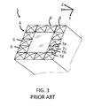
- FIG. 3 illustrates another prior art spinal implant 1 having a top bearing surface 4 that defines a plurality of pyramids 6 extending therefrom.
- the pyramids 6 aid in inhibiting movement of the spinal implant 1 relative to a vertebra (not shown) in a lengthwise-extending direction in which opposing first and second faces 7a, 7 b of the pyramid 6 are directed, and a widthwise-extending direction in which opposing third and fourth faces 7c, 7d of the pyramid 6 are directed.
- the pyramids 6 do not inhibit movement of the spinal implant 1 relative to the vertebra in other directions parallel to a plane defined by the bearing surface 4, or in a heightwise-extending vertical direction relative to the plane.
- a spinal implant that includes a body extending in direction at least substantially along a body axis, between a first end portion and a second end portion.
- the spinal implant also includes a first bearing surface disposed relative to the first end portion, and defining a first relief pattern that is configured to inhibit movement of the spinal implant relative to one or more vertebrae in at least substantially all directions.
- a method for manufacturing a spinal implant includes the step of selective laser sintering a body extending in direction at least substantially along a body axis, between a first end portion and a second end portion, and having a first bearing surface disposed relative to the first end portion, the first bearing surface defining a first relief pattern that is configured to inhibit movement of the spinal implant relative to one or more vertebrae in at least substantially all directions.
- the present disclosure describes a spinal implant 10, and a method for manufacturing the spinal implant 10.
- the present disclosure describes aspects of the present invention with reference to the exemplary embodiments illustrated in the drawings; however, aspects of the present invention are not limited to the exemplary embodiments illustrated in the drawings.
- the present disclosure may describe one or more features as having a length extending relative to an x-axis, a width extending relative to a y-axis, and/or a height extending relative to a z-axis.
- the drawings illustrate the respective axes.
- the spinal implant 10 includes a first bearing surface 12 and a second bearing surface 14 positioned at opposing ends of the spinal implant 10.
- the first and second bearing surfaces 12, 14 each define a relief pattern that is configured to inhibit movement of the spinal implant 10 relative to one or more vertebrae in at least substantially all directions.
- the present spinal implant 10 thus offers significant advantages over prior art spinal implants, which only prevent such movement in some directions.
- the spinal implant 10 includes a body 16 that: (ii) extends in a lengthwise direction between a first side surface 18 and a second side surface 20; (iii) extends in a widthwise direction between a front surface 22 and a rear surface 24; and (iii) extends in a heightwise direction between a first end portion 26 and an opposing second end portion 28 at least substantially along a body axis 30.
- the first bearing surface 12 is disposed relative to the first end portion 26, and the second bearing surface 14 is disposed relative to the second end portion 28.
- the distance between the first and second end portions 28, 30 is equal to or less than approximately 3 inches.
- the first and second bearing surfaces 12, 14 each define a plurality of protrusions 32 integrally connected therewith, and extending therefrom, which collectively define the respective relief patterns of the first and second bearing surfaces 12, 14.
- the protrusions 32 each have an at least generally conical shape.
- the protrusions 32 each define a base 34 integrally connected to the respective bearing surface 12, 14, and a tip 36 at a distal end of the protrusion 32.
- the base 34 defines a base width 38
- the tip 36 defines a tip width 40.
- the base width 38 is greater than the tip width 40.
- each protrusion 32 is truncated, blunted, and/or rounded.
- the base 34 of each protrusion 32 defines a tapered or convex surface that provides a smooth and/or rounded transition between the surface of the protrusion 32 and the respective bearing surface 12, 14 with which it is integrally formed.
- At least one of the protrusions 32 is configured such that the tip 36 of the protrusion 32 overhangs the base 34 of the protrusion 32. That is, the tip 36 of the protrusion 32 passes through a plane extending perpendicular to the respective bearing surface 12, 14 at the perimeter of the protrusion base 34.
- the protrusions 32 can have a tooth-like or hook-like conical shape.
- the protrusions 32 can effectively form a "hook" that can engage a vertebra in an interlocking event, which can thereby inhibit relative movement of the spinal implant 10 relative to the vertebra along an axis at least substantially perpendicular to the respective bearing surface 12, 14 of the spinal implant 10.
- the protrusions 32 each extend along a protrusion axis 42 that passes through the apex of the protrusion 32.
- One or more of the protrusions 32 are oriented obliquely relative to the respective bearing surface 12, 14 with which they are integrally formed. That is, the respective protrusion axes 42 are disposed at one or more non-parallel and non-perpendicular angles 44 relative to the body axis 30.
- the protrusions 32 on a respective bearing surface 12, 14 can define a plurality of different angles 44 between the respective protrusion axes 42 and the respective bearing surface 12, 14.
- the angles 44 of the protrusions 32 can be randomly selected (e.g., by a drafting program or the like), or can have the appearance of being randomly selected, within a predetermined range (e.g., between 10° and 80°).
- the protrusions 32 on a respective bearing surface 12, 14 can be oriented in a plurality of different directions relative to the body axis 30.
- the respective protrusion axes 42 collectively extend in generally all directions towards and/or away from the body axis 30.
- the respective protrusion axes 42 intersect with the respective planes defined by each of the first side surface 18, the second side surface 20, the front surface 22, and the rear surface 24 of the body 16 at a plurality of different lengthwise, widthwise, and/or heightwise positions on the respective planes.
- the orientation of the protrusions 32 can be randomly selected (e.g., by a drafting program or the like), or can have the appearance of being randomly selected.
- the protrusions 32 each define a height 46 equal to the distance extending between the respective bearing surface 12, 14 and the tip 36 of the respective protrusion 32 in a direction at least substantially parallel to the body axis 30.
- the heights 46 of the protrusions 32 can vary depending on the procedure for which the spinal implant 10 is to be used, one or more physiological facts of the patient (e.g., sizes of the patient's vertebrae), and/or one or more other design considerations. In some embodiments, for example, the heights 46 of the protrusions 32 are between 1 mm and 3 mm. In some embodiments (see FIGS. 8 and 12 ), the protrusions 32 all have substantially the same height 46.
- the respective protrusions 32 of at least one of the first and second bearing surfaces 12, 14 have a plurality of different heights 46a, 46b.
- the different heights 46 can be achieved by varying the height at which one or more of the protrusions 32 are truncated, blunted, and/or rounded.
- the different heights 46 can additionally or alternatively be achieved by providing the base 34 of one or more of the protrusions 32 with a different shape relative to the bases 34of the other protrusions 32 on the respective bearing surface 12, 14, and/or by providing one or more protrusions 32 with a different angle 44 relative to the other protrusions 32 on the respective bearing surface 12, 14.
- the protrusions 32 can have heights 46 that are randomly selected (or that have the appearance of being randomly selected) to be with a predetermine height range (e.g., 1 mm to 3 mm).
- the body 16 of the spinal implant 10 includes an aperture 48 extending between the first and second bearing surfaces 12, 14.
- a known fixation device (not shown) can be used to prevent movement of the spinal implant 10 relative to one or more vertebrae.
- a method for manufacturing the spinal implant 10 involves use of selective laser sintering (SLS), which is an additive manufacturing technique that uses electromagnetic radiation from a laser to fuse small particles of powders into a mass that has a desired three-dimensional shape.
- SLS selective laser sintering
- the present method involves the following steps, the order of which can vary: (i) using a laser to selectively fuse powdered material by scanning two-dimensional cross-sections according to a three dimensional digital description of the part (also known as a "build file") on the surface of a powder bed; (ii) after a cross-section is scanned, lowering the powder bed by one layer thickness; (iii) applying a new layer of material; and (iv) rescanning the powder bed. Steps (i)-(iv) are repeated until the desired three-dimensional shape part is completed.
- the powder bed used in the method includes a polymeric powder material, including, for example, a polyaryletherketone (“PAEK”) powder material.
- PEAK powder materials are particularly useful here because they are characterized by a low flammability, a good biocompatibility, and a high resistance against hydrolysis and radiation. The thermal resistance at elevated temperatures as well as the chemical resistance distinguishes PAEK materials from ordinary plastic powders.
- a PAEK powder material can include be one or more powder materials selected from the group consisting of polyetheretherketone (“PEEK”), polyetherketone ketone (“PEKK”), polyetherketone (“PEK”), polyetheretherketoneketone (“PEEKK”) or polyetherketoneetherketoneketone (“PEKEKK”).
- PEKK powder material available under the brand name OXPEKK® from Oxford Performance Materials, Inc. in South Windsor, Connecticut.
- Specimens fabricated from OXPEKK® polymer have been subjected to biocompatibility testing according to ISO 10993 and USP ⁇ 85> standards, and have met all applicable criteria for devices with permanent bone and tissue body contact with the additional potential to contact the cerebrospinal fluid.
- test specimens have been subjected to a successful sterilization validation.
- PEKK is a copolymer (AB type EKK/EKK).
- the examples described herein pertain to the 60/40 PEKK copolymer sold under brand name OXPEKK®. It should be understood, however, that the present invention is not limited to any specific blend of PEKK resin, and that different blends may be used.
- the method can additionally or alternatively include one or more of the following steps, the order of which can vary: (a) verifying that that the unused PEKK powder material is adequately dry; (b) loading the unused PEKK powder material into a SLS machine; (c) loading the PEKK powder material is loaded into a hopper, or the like, from which an SLS machine can distribute sequential layers of powder onto a powder bed of the SLS machine for sintering; (d) loading the part geometries (also known as the "build definition") into a computer associated with the SLS machine; (e) pre-heating the SLS machine according to known methods; (f) setting the bed temperature to a temperature as determined by characterization of the PEKK powder material; (g) setting the laser power to a power specified by the vendor and/or to a power determined from earlier runs of the SLS process; (h) setting a powder layer thickness (e.g., 125 microns); (i) after the layer-wise build
Landscapes
- Health & Medical Sciences (AREA)
- Engineering & Computer Science (AREA)
- Biomedical Technology (AREA)
- Orthopedic Medicine & Surgery (AREA)
- Materials Engineering (AREA)
- Chemical & Material Sciences (AREA)
- Manufacturing & Machinery (AREA)
- Heart & Thoracic Surgery (AREA)
- General Health & Medical Sciences (AREA)
- Oral & Maxillofacial Surgery (AREA)
- Cardiology (AREA)
- Vascular Medicine (AREA)
- Life Sciences & Earth Sciences (AREA)
- Animal Behavior & Ethology (AREA)
- Transplantation (AREA)
- Public Health (AREA)
- Veterinary Medicine (AREA)
- Neurology (AREA)
- Physics & Mathematics (AREA)
- Optics & Photonics (AREA)
- Mechanical Engineering (AREA)
- Prostheses (AREA)
Abstract
Description
- The present disclosure claims priority to
U.S. Provisional Patent Application No. 62/039,148, filed August 19, 2014 - The present invention relates to a medical interbody implant, and more specifically relates to a spinal implant that defines a bearing surface configured to inhibit movement of the implant relative to one or more adjacent vertebra and to promote fusion of the adjacent vertebra to the spinal implant. The present invention further relates to a method of manufacturing a spinal implant, and more specifically a method of using selective laser sintering to manufacture a spinal implant having the bearing surface.
- Spinal fusion is a surgical technique in which a spinal implant is used to join one or more vertebrae. In preparation for the spinal fusion, the one or more intervertebral discs between the vertebrae are removed. The spinal implant is surgically inserted between the vertebrae in order to maintain spine alignment and intervertebral disc height.
FIG. 1 , for example, illustrates a prior artspinal implant 1 inserted between adjacent first andsecond vertebrae - A disadvantage of known spinal implants is that external forces can cause a movement (also known as "slippage" or "floating") of the spinal implant relative to one or more of the vertebrae. The likelihood of such a translation is particularly high during the period between 6 to 12 months after surgery, when the fusion process typically takes place. Such movement is disadvantageous, because the positioning of the spinal implant relative to the vertebrae requires a high degree of precision in order to provide the desired therapeutic effect. Any unwanted movement can negatively impact any therapeutic and any benefit to the patient.
- It is known to form a relief pattern on one or more bearing surfaces of the spinal implant in an attempt to inhibit movement of the spinal implant relative to a vertebra in a direction extending parallel and/or perpendicular to a bearing surface of the vertebra.
FIG. 2 , for example, illustrates a prior artspinal implant 1 having a top bearingsurface 4 that defines a plurality of linear grooves andridges 5 in the top bearingsurface 4 of the prior artspinal implant 1. The grooves andridges 5 aid in inhibiting movement of thespinal implant 1 relative to a vertebra (not shown) in a widthwise direction extending perpendicular to the grooves andridges 5. However, the grooves andridges 5 do not inhibit movement of thespinal implant 1 relative to a vertebra (not shown) in a lengthwise direction extending parallel to the grooves andridges 5 or in other directions parallel to a plane defined by the top bearingsurface 4.FIG. 3 illustrates another prior artspinal implant 1 having a top bearingsurface 4 that defines a plurality ofpyramids 6 extending therefrom. Thepyramids 6 aid in inhibiting movement of thespinal implant 1 relative to a vertebra (not shown) in a lengthwise-extending direction in which opposing first andsecond faces pyramid 6 are directed, and a widthwise-extending direction in which opposing third andfourth faces pyramid 6 are directed. However, thepyramids 6 do not inhibit movement of thespinal implant 1 relative to the vertebra in other directions parallel to a plane defined by thebearing surface 4, or in a heightwise-extending vertical direction relative to the plane. - Aspects of the present invention are directed to these and other problems.
- According to an aspect of the present invention, a spinal implant is provided that includes a body extending in direction at least substantially along a body axis, between a first end portion and a second end portion. The spinal implant also includes a first bearing surface disposed relative to the first end portion, and defining a first relief pattern that is configured to inhibit movement of the spinal implant relative to one or more vertebrae in at least substantially all directions.
- According to another aspect of the present invention, a method for manufacturing a spinal implant is provided that includes the step of selective laser sintering a body extending in direction at least substantially along a body axis, between a first end portion and a second end portion, and having a first bearing surface disposed relative to the first end portion, the first bearing surface defining a first relief pattern that is configured to inhibit movement of the spinal implant relative to one or more vertebrae in at least substantially all directions.
- In addition to, or as an alternative to, one or more of the features described above, further aspects of the present invention can include one or more of the following features, individually or in combination:
- the spinal implant further includes second bearing surface disposed relative to the second end portion, and defining a second relief pattern that is configured to inhibit movement of the spinal implant relative to one or more vertebrae in at least substantially all directions;
- the first bearing surface defines a plurality of protrusions integrally connected therewith, and extending therefrom, which collectively define the first relief pattern;
- the plurality of protrusions each have an at least generally conical shape, and each defining a base integrally connected to the first bearing surface, and a tip at a distal end of the respective protrusion;
- the base defines a base width, the tip defines a tip width, and the base width is greater than the tip width;
- at least one of the plurality of protrusions is configured such that the tip overhangs the base;
- at least one of the plurality of protrusions has a hook-like conical shape;
- the tip is truncated, blunted, and/or rounded;
- the base defines a tapered and/or convex surface that provides a smooth and/or rounded transition between the surface of the respective protrusion and the firts bearing surface;
- each of the plurality of protrusions extends along a protrusion axis that passes through an apex of the respective protrusion;
- at least one of the plurality of protrusions is oriented obliquely relative to the first bearing surface;
- the plurality of protrusions define a plurality of angles between the respective protrusions and the first bearing surface;
- the respective angles are randomly selected to be within a predetermined range of angles;
- the plurality of protrusions are oriented in a plurality of different directions relative to the body axis;
- the respective orientations are randomly selected;
- each of the plurality of protrusions extends along a protrusion axis that passes through an apex of the respective protrusion; and the respective protrusion axes extend in generally all directions towards and/or away from the body axis;
- the body defines a plurality of side surfaces extending substantially perpendicular to the first bearing surface between the first end portion and the second portion of the body; and the respective protrusion axes of the plurality of protrusions intersect with respective planes defined by each of the plurality of side surfaces at a plurality of positions on the respective planes;
- the plurality of protrusions define a plurality of heights extending between their respective tips and the first bearing surface;
- the respective heights are randomly selected;
- the respective heights of the plurality of protrusions is between 1 mm and 3 mm;
- the selective laser sintering step involves using a laser to selectively fuse a polymeric powder material;
- the polymeric powdered material is a polyaryletherketone ("PAEK") powder material; and
- the PAEK powder material includes at least one material selected from the group consisting of: polyetheretherketone ("PEEK"), polyetherketone ketone ("PEKK"), polyetherketone ("PEK"), polyetheretherketoneketone ("PEEKK") or polyetherketoneetherketoneketone ("PEKEKK").
- These and other aspects of the present invention will become apparent in light of the drawings and detailed description provided below.
-
-
FIG. 1 illustrates a perspective view of a human spine with a prior art spinal implant. -
FIG. 2 illustrates a perspective view of another prior art spinal implant. -
FIG. 3 illustrates a perspective view of another prior art spinal implant. -
FIG. 4 illustrates a front elevation view of a first embodiment of the present spinal implant. -
FIG. 5 illustrates a perspective view of the spinal implant ofFIG. 4 . -
FIG. 6 illustrates a perspective view of the top end portion of the spinal implant ofFIG. 4 . -
FIG. 7 illustrates a plan view of the top end portion of the spinal implant ofFIG. 4 . -
FIG. 8 illustrates a front elevation view of the top end portion of the spinal implant ofFIG. 4 . -
FIG. 9 illustrates a side elevation view of the top end portion of the spinal implant ofFIG. 4 . -
FIG. 10 illustrates a plan view of the bottom end portion of the spinal implant ofFIG. 4 . -
FIG. 11 illustrates a perspective view of the top end portion of a second embodiment of the present spinal implant. -
FIG. 12 illustrates a side elevation view of the top end portion of the spinal implant ofFIG. 11 . -
FIG. 13 illustrates a perspective view of the top end portion of a third embodiment of the present spinal implant. -
FIG. 14 illustrates a plan view of the top end portion of a fourth embodiment of the present spinal implant. -
FIG. 15 illustrates a front elevation view of the top end portion of the spinal implant ofFIG. 14 . - Referring to
FIGS. 4-15 , the present disclosure describes aspinal implant 10, and a method for manufacturing thespinal implant 10. - The present disclosure describes aspects of the present invention with reference to the exemplary embodiments illustrated in the drawings; however, aspects of the present invention are not limited to the exemplary embodiments illustrated in the drawings. The present disclosure may describe one or more features as having a length extending relative to an x-axis, a width extending relative to a y-axis, and/or a height extending relative to a z-axis. The drawings illustrate the respective axes.
- Referring to
FIGS. 4 and 5 , thespinal implant 10 includes afirst bearing surface 12 and asecond bearing surface 14 positioned at opposing ends of thespinal implant 10. The first and second bearing surfaces 12, 14 each define a relief pattern that is configured to inhibit movement of thespinal implant 10 relative to one or more vertebrae in at least substantially all directions. The presentspinal implant 10 thus offers significant advantages over prior art spinal implants, which only prevent such movement in some directions. - The
spinal implant 10 includes abody 16 that: (ii) extends in a lengthwise direction between afirst side surface 18 and asecond side surface 20; (iii) extends in a widthwise direction between afront surface 22 and arear surface 24; and (iii) extends in a heightwise direction between afirst end portion 26 and an opposingsecond end portion 28 at least substantially along abody axis 30. Thefirst bearing surface 12 is disposed relative to thefirst end portion 26, and thesecond bearing surface 14 is disposed relative to thesecond end portion 28. The distance between the first andsecond end portions - The first and second bearing surfaces 12, 14 each define a plurality of
protrusions 32 integrally connected therewith, and extending therefrom, which collectively define the respective relief patterns of the first and second bearing surfaces 12, 14. - Referring to
FIGS. 8 and12 , theprotrusions 32 each have an at least generally conical shape. Theprotrusions 32 each define a base 34 integrally connected to therespective bearing surface tip 36 at a distal end of theprotrusion 32. Thebase 34 defines abase width 38, and thetip 36 defines atip width 40. Thebase width 38 is greater than thetip width 40. - In some embodiments (see
FIGS. 4-12 and14-15 ), thetip 36 of eachprotrusion 32 is truncated, blunted, and/or rounded. In some embodiments (seeFIGS. 6 ,8 ,9 , etc.), thebase 34 of eachprotrusion 32 defines a tapered or convex surface that provides a smooth and/or rounded transition between the surface of theprotrusion 32 and therespective bearing surface - In some embodiments (see, e.g.,
FIG. 13 ), at least one of theprotrusions 32 is configured such that thetip 36 of theprotrusion 32 overhangs thebase 34 of theprotrusion 32. That is, thetip 36 of theprotrusion 32 passes through a plane extending perpendicular to therespective bearing surface protrusion base 34. In some of these and other embodiments, theprotrusions 32 can have a tooth-like or hook-like conical shape. In such embodiments, theprotrusions 32 can effectively form a "hook" that can engage a vertebra in an interlocking event, which can thereby inhibit relative movement of thespinal implant 10 relative to the vertebra along an axis at least substantially perpendicular to therespective bearing surface spinal implant 10. - Referring to
FIGS. 6 ,8 , and11-13 , theprotrusions 32 each extend along aprotrusion axis 42 that passes through the apex of theprotrusion 32. One or more of theprotrusions 32 are oriented obliquely relative to therespective bearing surface non-perpendicular angles 44 relative to thebody axis 30. - Referring to
FIGS. 8 and12 , in some embodiments, theprotrusions 32 on arespective bearing surface different angles 44 between the respective protrusion axes 42 and therespective bearing surface angles 44 of theprotrusions 32 can be randomly selected (e.g., by a drafting program or the like), or can have the appearance of being randomly selected, within a predetermined range (e.g., between 10° and 80°). - Referring to
FIGS. 6 ,11 ,13 , and14 , in some embodiments, theprotrusions 32 on arespective bearing surface body axis 30. In some embodiments, the respective protrusion axes 42 collectively extend in generally all directions towards and/or away from thebody axis 30. In some embodiments, the respective protrusion axes 42 intersect with the respective planes defined by each of thefirst side surface 18, thesecond side surface 20, thefront surface 22, and therear surface 24 of thebody 16 at a plurality of different lengthwise, widthwise, and/or heightwise positions on the respective planes. In such embodiments, the orientation of theprotrusions 32 can be randomly selected (e.g., by a drafting program or the like), or can have the appearance of being randomly selected. - Referring to
FIGS. 8 ,12 , and15 , theprotrusions 32 each define aheight 46 equal to the distance extending between therespective bearing surface tip 36 of therespective protrusion 32 in a direction at least substantially parallel to thebody axis 30. Theheights 46 of theprotrusions 32 can vary depending on the procedure for which thespinal implant 10 is to be used, one or more physiological facts of the patient (e.g., sizes of the patient's vertebrae), and/or one or more other design considerations. In some embodiments, for example, theheights 46 of theprotrusions 32 are between 1 mm and 3 mm. In some embodiments (seeFIGS. 8 and12 ), theprotrusions 32 all have substantially thesame height 46. In other embodiments (seeFIG. 15 ), therespective protrusions 32 of at least one of the first and second bearing surfaces 12, 14 have a plurality ofdifferent heights different heights 46 can be achieved by varying the height at which one or more of theprotrusions 32 are truncated, blunted, and/or rounded. Thedifferent heights 46 can additionally or alternatively be achieved by providing thebase 34 of one or more of theprotrusions 32 with a different shape relative to the bases 34of theother protrusions 32 on therespective bearing surface more protrusions 32 with adifferent angle 44 relative to theother protrusions 32 on therespective bearing surface protrusions 32 can haveheights 46 that are randomly selected (or that have the appearance of being randomly selected) to be with a predetermine height range (e.g., 1 mm to 3 mm). - In some embodiments, including the illustrated embodiments, the
body 16 of thespinal implant 10 includes anaperture 48 extending between the first and second bearing surfaces 12, 14. - In some embodiments, a known fixation device (not shown) can be used to prevent movement of the
spinal implant 10 relative to one or more vertebrae. - The cost and logistics of manufacturing a
spinal implant 10 havingprotrusions 32 as described above (e.g., withtips 36 that overhang the bases 34) makes conventional manufacturing techniques (e.g., subtractive manufacturing techniques, machining, etc.) impossible. Accordingly, a method for manufacturing thespinal implant 10 involves use of selective laser sintering (SLS), which is an additive manufacturing technique that uses electromagnetic radiation from a laser to fuse small particles of powders into a mass that has a desired three-dimensional shape. - The present method involves the following steps, the order of which can vary: (i) using a laser to selectively fuse powdered material by scanning two-dimensional cross-sections according to a three dimensional digital description of the part (also known as a "build file") on the surface of a powder bed; (ii) after a cross-section is scanned, lowering the powder bed by one layer thickness; (iii) applying a new layer of material; and (iv) rescanning the powder bed. Steps (i)-(iv) are repeated until the desired three-dimensional shape part is completed.
- The powder bed used in the method includes a polymeric powder material, including, for example, a polyaryletherketone ("PAEK") powder material. PEAK powder materials are particularly useful here because they are characterized by a low flammability, a good biocompatibility, and a high resistance against hydrolysis and radiation. The thermal resistance at elevated temperatures as well as the chemical resistance distinguishes PAEK materials from ordinary plastic powders. A PAEK powder material can include be one or more powder materials selected from the group consisting of polyetheretherketone ("PEEK"), polyetherketone ketone ("PEKK"), polyetherketone ("PEK"), polyetheretherketoneketone ("PEEKK") or polyetherketoneetherketoneketone ("PEKEKK").
- In some embodiments, it can be especially advantageous to use a PEKK powder material, available under the brand name OXPEKK® from Oxford Performance Materials, Inc. in South Windsor, Connecticut. Specimens fabricated from OXPEKK® polymer have been subjected to biocompatibility testing according to ISO 10993 and USP <85> standards, and have met all applicable criteria for devices with permanent bone and tissue body contact with the additional potential to contact the cerebrospinal fluid. Such test specimens have been subjected to a successful sterilization validation. It should be understood that there are different blends of PEKK powder materials. Unlike other PAEK materials, PEKK is a copolymer (AB type EKK/EKK). The examples described herein pertain to the 60/40 PEKK copolymer sold under brand name OXPEKK®. It should be understood, however, that the present invention is not limited to any specific blend of PEKK resin, and that different blends may be used.
- In embodiments in which the method involves an unused PEKK powder material, the method can additionally or alternatively include one or more of the following steps, the order of which can vary: (a) verifying that that the unused PEKK powder material is adequately dry; (b) loading the unused PEKK powder material into a SLS machine; (c) loading the PEKK powder material is loaded into a hopper, or the like, from which an SLS machine can distribute sequential layers of powder onto a powder bed of the SLS machine for sintering; (d) loading the part geometries (also known as the "build definition") into a computer associated with the SLS machine; (e) pre-heating the SLS machine according to known methods; (f) setting the bed temperature to a temperature as determined by characterization of the PEKK powder material; (g) setting the laser power to a power specified by the vendor and/or to a power determined from earlier runs of the SLS process; (h) setting a powder layer thickness (e.g., 125 microns); (i) after the layer-wise build is performed, cooling the resulting powder cake at a controlled rate (e.g., between 1 and 100 degrees Celsius per hour); (j) after powder cake has achieve at least substantially room temperature, removing the spinal implant 10 therefrom. Regarding step (i), it should be appreciated by a person having ordinary skill in the art that the rate of cooling depends on the dimensions of the cake, with deeper beds typically requiring more time to cool.
- While several embodiments have been disclosed, it will be apparent to those of ordinary skill in the art that aspects of the present invention include many more embodiments and implementations. Accordingly, aspects of the present invention are not to be restricted except in light of the attached claims and their equivalents. It will also be apparent to those of ordinary skill in the art that variations and modifications can be made without departing from the true scope of the present disclosure. For example, in some instances, one or more features disclosed in connection with one embodiment can be used alone or in combination with one or more features of one or more other embodiments.
Claims (24)
- A spinal implant (10), comprising:a body (16) extending in direction at least substantially along a body axis (30), between a first end portion (26) and a second end portion (28);a first bearing surface (12) disposed relative to the first end portion (26), and defining a first relief pattern that is configured to inhibit movement of the spinal implant (10) relative to one or more vertebrae (2, 3) in at least substantially all directions.
- The spinal implant (10) of claim 1, further comprising a second bearing surface (14) disposed relative to the second end portion (28), and defining a second relief pattern that is configured to inhibit movement of the spinal implant (10) relative to one or more vertebrae (2, 3) in at least substantially all directions.
- The spinal implant (10) of claim 1, wherein the first bearing surface (12) defines a plurality of protrusions (32) integrally connected therewith, and extending therefrom, which collectively define the first relief pattern.
- The spinal implant (10) of claim 1, wherein the plurality of protrusions (32) each have an at least generally conical shape, and each defining a base (34) integrally connected to the first bearing surface (12), and a tip (36) at a distal end of the respective protrusion.
- The spinal implant (10) of claim 4, wherein the base (34) defines a base width (38), the tip (36) defines a tip width (40), and the base width is greater than the tip width.
- The spinal implant (10) of claim 4, wherein at least one of the plurality of protrusions (32) is configured such that the tip (36) overhangs the base (34).
- The spinal implant (10) of claim 4, wherein at least one of the plurality of protrusions (32) has a hook-like conical shape.
- The spinal implant (10) of claim 4, wherein the tip (36) is truncated, blunted, and/or rounded.
- The spinal implant (10) of claim 4, wherein the base (34) defines a tapered and/or convex surface that provides a smooth and/or rounded transition between the surface of the respective protrusion (32) and the firts bearing surface (12).
- The spinal implant (10) of claim 4, wherein each of the plurality of protrusions (32) extends along a protrusion axis (42) that passes through an apex of the respective protrusion.
- The spinal implant (10) of claim 4, wherein at least one of the plurality of protrusions (32) is oriented obliquely relative to the first bearing surface (12).
- The spinal implant (10) of claim 11, wherein the plurality of protrusions (32) define a plurality of angles (44) between the respective protrusions and the first bearing surface (12).
- The spinal implant (10) of claim 12, wherein the respective angles (44) are randomly selected to be within a predetermined range of angles.
- The spinal implant (10) of claim 4, wherein the plurality of protrusions (32) are oriented in a plurality of different directions relative to the body axis (30).
- The spinal implant (10) of claim 14, wherein the respective orientations are randomly selected.
- The spinal implant (10) of claim 14, wherein each of the plurality of protrusions (32) extends along a protrusion axis (42) that passes through an apex of the respective protrusion; and
wherein the respective protrusion axes (42) extend in generally all directions towards and/or away from the body axis (30). - The spinal implant (10) of claim 16, wherein the body (16) defines a plurality of side surfaces (18, 20, 22, 24) extending substantially perpendicular to the first bearing surface (12) between the first end portion (26) and the second portion (28) of the body; and
wherein the respective protrusion axes (42) of the plurality of protrusions (32) intersect with respective planes defined by each of the plurality of side surfaces (18, 20, 22, 24) at a plurality of positions on the respective planes. - The spinal implant (10) of claim 4, wherein the plurality of protrusions (32) define a plurality of heights (46) extending between their respective tips (36) and the first bearing surface (12).
- The spinal implant (10) of claim 18, wherein the respective heights (46) are randomly selected.
- The spinal implant (10) of claim 1, wherein the respective heights (46) of the plurality of protrusions (32) is between 1 mm and 3 mm.
- A method for manufacturing a spinal implant (10), comprising:selective laser sintering a body (16) extending in direction at least substantially along a body axis (30), between a first end portion (26) and a second end portion (28), and having a first bearing surface (12) disposed relative to the first end portion, the first bearing surface (12) defining a first relief pattern that is configured to inhibit movement of the spinal implant (10) relative to one or more vertebrae (2, 3) in at least substantially all directions.
- The method of claim 21, wherein the selective laser sintering step involves using a laser to selectively fuse a polymeric powder material.
- The method of claim 22, wherein the polymeric powdered material is a polyaryletherketone ("PAEK") powder material.
- The method of claim 23, wherein the PAEK powder material includes at least one material selected from the group consisting of:polyetheretherketone ("PEEK"), polyetherketone ketone ("PEKK"),polyetherketone ("PEK"), polyetheretherketoneketone ("PEEKK") orpolyetherketoneetherketoneketone ("PEKEKK").
Applications Claiming Priority (2)
| Application Number | Priority Date | Filing Date | Title |
|---|---|---|---|
| US201462039148P | 2014-08-19 | 2014-08-19 | |
| US14/828,099 US10105240B2 (en) | 2014-08-19 | 2015-08-17 | Spinal implant and method for fabricating the same |
Publications (2)
| Publication Number | Publication Date |
|---|---|
| EP2987626A1 true EP2987626A1 (en) | 2016-02-24 |
| EP2987626B1 EP2987626B1 (en) | 2020-05-13 |
Family
ID=53938175
Family Applications (1)
| Application Number | Title | Priority Date | Filing Date |
|---|---|---|---|
| EP15181570.1A Active EP2987626B1 (en) | 2014-08-19 | 2015-08-19 | Spinal implant and method for manufacturing the same |
Country Status (2)
| Country | Link |
|---|---|
| US (2) | US10105240B2 (en) |
| EP (1) | EP2987626B1 (en) |
Cited By (1)
| Publication number | Priority date | Publication date | Assignee | Title |
|---|---|---|---|---|
| CN108606860A (en) * | 2018-05-22 | 2018-10-02 | 广州迈普再生医学科技股份有限公司 | A kind of 3D printing Invasive lumbar fusion device of personalization and preparation method thereof |
Families Citing this family (32)
| Publication number | Priority date | Publication date | Assignee | Title |
|---|---|---|---|---|
| US10524928B2 (en) * | 2015-12-15 | 2020-01-07 | Globus Medical, Inc | Stabilized intervertebral spacer |
| USD816844S1 (en) | 2017-06-29 | 2018-05-01 | American Medical Ortho Systems LLC | Lumbar interbody implant |
| USD841167S1 (en) | 2017-08-16 | 2019-02-19 | American Medical Ortho Systems LLC | Lumbar interbody implant |
| EP3678602A4 (en) | 2017-09-08 | 2021-10-06 | Pioneer Surgical Technology, Inc. | INTERVERTEBRAL IMPLANTS, INSTRUMENTS AND PROCESSES |
| USD907771S1 (en) | 2017-10-09 | 2021-01-12 | Pioneer Surgical Technology, Inc. | Intervertebral implant |
| US10183442B1 (en) | 2018-03-02 | 2019-01-22 | Additive Device, Inc. | Medical devices and methods for producing the same |
| USD870889S1 (en) | 2018-03-02 | 2019-12-24 | Restor3D, Inc. | Cutout airway stent |
| USD870890S1 (en) | 2018-03-02 | 2019-12-24 | Restor3D, Inc. | Spiral airway stent |
| USD871577S1 (en) | 2018-03-02 | 2019-12-31 | Restor3D, Inc. | Studded airway stent |
| USD870888S1 (en) | 2018-03-02 | 2019-12-24 | Restor3D, Inc. | Accordion airway stent |
| US10555819B2 (en) | 2018-05-08 | 2020-02-11 | Globus Medical, Inc. | Intervertebral spinal implant |
| US10744003B2 (en) | 2018-05-08 | 2020-08-18 | Globus Medical, Inc. | Intervertebral spinal implant |
| US10682238B2 (en) | 2018-05-08 | 2020-06-16 | Globus Medical, Inc. | Intervertebral spinal implant |
| US11039931B2 (en) | 2019-02-01 | 2021-06-22 | Globus Medical, Inc. | Intervertebral spinal implant |
| US10889053B1 (en) | 2019-03-25 | 2021-01-12 | Restor3D, Inc. | Custom surgical devices and method for manufacturing the same |
| NL2023241B1 (en) * | 2019-05-31 | 2020-12-07 | Petrus Stegmann Johann | Intervertebral fusion cage |
| USD920516S1 (en) | 2020-01-08 | 2021-05-25 | Restor3D, Inc. | Osteotomy wedge |
| USD920517S1 (en) | 2020-01-08 | 2021-05-25 | Restor3D, Inc. | Osteotomy wedge |
| US10772732B1 (en) | 2020-01-08 | 2020-09-15 | Restor3D, Inc. | Sheet based triply periodic minimal surface implants for promoting osseointegration and methods for producing same |
| USD920515S1 (en) | 2020-01-08 | 2021-05-25 | Restor3D, Inc. | Spinal implant |
| US11499124B2 (en) | 2020-03-13 | 2022-11-15 | YFY Consumer Products, Co. | Solid granules used for cleaning agents |
| US11850144B1 (en) | 2022-09-28 | 2023-12-26 | Restor3D, Inc. | Ligament docking implants and processes for making and using same |
| US11806028B1 (en) | 2022-10-04 | 2023-11-07 | Restor3D, Inc. | Surgical guides and processes for producing and using the same |
| USD1051384S1 (en) | 2023-03-24 | 2024-11-12 | Restor3D, Inc. | Bone fixation pin |
| USD1053353S1 (en) | 2023-03-24 | 2024-12-03 | Restor3D, Inc. | Orthopedic screw |
| USD1118931S1 (en) * | 2023-03-31 | 2026-03-17 | Restor3D, Inc. | Orthopedic implant |
| USD1122446S1 (en) | 2023-05-10 | 2026-04-14 | Restor3D, Inc. | Talus implant |
| USD1124342S1 (en) | 2023-05-10 | 2026-04-28 | Restor3D, Inc. | Talus implant |
| USD1052732S1 (en) | 2023-05-25 | 2024-11-26 | Restor3D, Inc. | Subtalar wedge |
| US11960266B1 (en) | 2023-08-23 | 2024-04-16 | Restor3D, Inc. | Patient-specific medical devices and additive manufacturing processes for producing the same |
| US12591216B1 (en) | 2024-02-02 | 2026-03-31 | Restor3D, Inc. | Patient-specific medical devices based on bone density and processes for producing the same |
| US12605251B1 (en) | 2025-03-28 | 2026-04-21 | Restor3D, Inc. | Patient-specific shoulder implants and processes for producing and using the same |
Citations (4)
| Publication number | Priority date | Publication date | Assignee | Title |
|---|---|---|---|---|
| US20100217395A1 (en) * | 2006-07-24 | 2010-08-26 | Rudolf Bertagnoli | Intervertebral implant with keel |
| WO2011126490A1 (en) * | 2010-04-09 | 2011-10-13 | Synthes Usa, Llc | Endplate of an intervertebral implant and implant |
| WO2013085947A1 (en) * | 2011-12-05 | 2013-06-13 | Oxford Performance Materials, Llc | Method for processing paek and articles manufactured from the same |
| WO2014018325A1 (en) * | 2012-07-25 | 2014-01-30 | Titan Spine, Llc | Implants having three distinct surfaces |
Family Cites Families (13)
| Publication number | Priority date | Publication date | Assignee | Title |
|---|---|---|---|---|
| AU2001275253A1 (en) * | 2000-06-05 | 2001-12-17 | Laser Fire | Orthopedic implant and method of making metal articles |
| WO2004016217A2 (en) * | 2002-08-15 | 2004-02-26 | David Gerber | Controlled artificial intervertebral disc implant |
| US8814939B2 (en) * | 2005-05-06 | 2014-08-26 | Titan Spine, Llc | Implants having three distinct surfaces |
| US7927373B2 (en) * | 2005-10-31 | 2011-04-19 | Depuy Spine, Inc. | Intervertebral disc prosthesis |
| US8202320B2 (en) * | 2005-10-31 | 2012-06-19 | Depuy Spine, Inc. | Intervertebral disc prosthesis |
| US7850736B2 (en) * | 2006-04-13 | 2010-12-14 | Warsaw Orthopedic, Inc. | Vertebral fusion implants and methods of use |
| BRPI0820129B8 (en) * | 2007-12-19 | 2021-06-22 | Angiotech Pharm Inc | process of formation of a self-retaining suture and self-retaining suture |
| KR20110009216A (en) * | 2008-05-05 | 2011-01-27 | 스피날모우션, 인코포레이티드 | Polyaryletherketone artificial intervertebral disc |
| US20110035010A1 (en) * | 2009-08-07 | 2011-02-10 | Ebi, Llc | Toroid-shaped spinal disc |
| WO2011016989A2 (en) * | 2009-08-07 | 2011-02-10 | Ebi, Llc | Toroid-shaped spinal disc |
| US9301853B2 (en) * | 2010-04-09 | 2016-04-05 | DePuy Synthes Products, Inc. | Holder for implantation and extraction of prosthesis |
| CA2880825C (en) * | 2012-03-20 | 2021-03-16 | Titan Spine, Llc | Friction-fit spinal endplate and endplate-preserving method |
| US10507119B2 (en) * | 2013-12-19 | 2019-12-17 | Aesculap Implant Systems, Llc | Spinal interbody device, system and method |
-
2015
- 2015-08-17 US US14/828,099 patent/US10105240B2/en active Active
- 2015-08-19 EP EP15181570.1A patent/EP2987626B1/en active Active
-
2018
- 2018-09-20 US US16/136,968 patent/US10881529B2/en active Active
Patent Citations (4)
| Publication number | Priority date | Publication date | Assignee | Title |
|---|---|---|---|---|
| US20100217395A1 (en) * | 2006-07-24 | 2010-08-26 | Rudolf Bertagnoli | Intervertebral implant with keel |
| WO2011126490A1 (en) * | 2010-04-09 | 2011-10-13 | Synthes Usa, Llc | Endplate of an intervertebral implant and implant |
| WO2013085947A1 (en) * | 2011-12-05 | 2013-06-13 | Oxford Performance Materials, Llc | Method for processing paek and articles manufactured from the same |
| WO2014018325A1 (en) * | 2012-07-25 | 2014-01-30 | Titan Spine, Llc | Implants having three distinct surfaces |
Cited By (1)
| Publication number | Priority date | Publication date | Assignee | Title |
|---|---|---|---|---|
| CN108606860A (en) * | 2018-05-22 | 2018-10-02 | 广州迈普再生医学科技股份有限公司 | A kind of 3D printing Invasive lumbar fusion device of personalization and preparation method thereof |
Also Published As
| Publication number | Publication date |
|---|---|
| EP2987626B1 (en) | 2020-05-13 |
| US10105240B2 (en) | 2018-10-23 |
| US20160051371A1 (en) | 2016-02-25 |
| US20190015217A1 (en) | 2019-01-17 |
| US10881529B2 (en) | 2021-01-05 |
Similar Documents
| Publication | Publication Date | Title |
|---|---|---|
| US10881529B2 (en) | Spinal implant and method for fabricating the same | |
| US12053186B2 (en) | Spring-fit surgical guides | |
| US20230191689A1 (en) | Porous Structures Produced By Additive Layer Manufacturing | |
| JP6590788B2 (en) | Composite interbody device and method | |
| US12251145B2 (en) | Flexible construct for femoral reconstruction | |
| US8142508B1 (en) | Spinal cage having deployable member which is removable | |
| US20130184826A1 (en) | Bioabsorbable enclosures | |
| US12508134B2 (en) | Augmented, just-in-time, patient-specific implant manufacture | |
| US20160095710A1 (en) | Implants comprising anchoring elements | |
| JP2020533070A (en) | Intervertebral implants, instruments, and methods | |
| CN111565916A (en) | System and method for manufacturing spinal implant | |
| CN111936087A (en) | Surface texture of three-dimensional porous structure for bone ingrowth and method of making | |
| WO2014090908A1 (en) | Surgical guiding tools for orthopedic surgery and systems and methods of manufacturing the same | |
| EP3157470B1 (en) | Corpectomy implants with roughened bioactive lateral surfaces | |
| EP3758634B1 (en) | Spinal implants with customized density and 3D printing of spinal implants | |
| CN106137462B (en) | Particulate heterogeneous bone substitute material and method of making free-form porous body | |
| WO2011060312A2 (en) | Controlled randomized porous structures and methods for making same | |
| WO2015049385A2 (en) | Surgical guide system | |
| CN107174325B (en) | Spinal Fixation Components | |
| US20150359637A1 (en) | Micro and macro texturing of machined objects | |
| CN106137358B (en) | Bone engaging member | |
| RU2669860C1 (en) | Formed membrane for osteoplastics manufacturing method | |
| KR20160016372A (en) | Spinal implant cage and manufacturing method thereof |
Legal Events
| Date | Code | Title | Description |
|---|---|---|---|
| PUAI | Public reference made under article 153(3) epc to a published international application that has entered the european phase |
Free format text: ORIGINAL CODE: 0009012 |
|
| AK | Designated contracting states |
Kind code of ref document: A1 Designated state(s): AL AT BE BG CH CY CZ DE DK EE ES FI FR GB GR HR HU IE IS IT LI LT LU LV MC MK MT NL NO PL PT RO RS SE SI SK SM TR |
|
| AX | Request for extension of the european patent |
Extension state: BA ME |
|
| 17P | Request for examination filed |
Effective date: 20160818 |
|
| RBV | Designated contracting states (corrected) |
Designated state(s): AL AT BE BG CH CY CZ DE DK EE ES FI FR GB GR HR HU IE IS IT LI LT LU LV MC MK MT NL NO PL PT RO RS SE SI SK SM TR |
|
| STAA | Information on the status of an ep patent application or granted ep patent |
Free format text: STATUS: EXAMINATION IS IN PROGRESS |
|
| 17Q | First examination report despatched |
Effective date: 20190628 |
|
| REG | Reference to a national code |
Ref country code: DE Ref legal event code: R079 Ref document number: 602015052653 Country of ref document: DE Free format text: PREVIOUS MAIN CLASS: B29C0067040000 Ipc: A61F0002300000 |
|
| RIC1 | Information provided on ipc code assigned before grant |
Ipc: B29K 71/00 20060101ALI20191008BHEP Ipc: B29C 64/153 20170101ALI20191008BHEP Ipc: B33Y 80/00 20150101ALI20191008BHEP Ipc: A61F 2/30 20060101AFI20191008BHEP Ipc: B29L 31/00 20060101ALI20191008BHEP Ipc: A61F 2/44 20060101ALI20191008BHEP Ipc: B33Y 10/00 20150101ALI20191008BHEP |
|
| GRAP | Despatch of communication of intention to grant a patent |
Free format text: ORIGINAL CODE: EPIDOSNIGR1 |
|
| STAA | Information on the status of an ep patent application or granted ep patent |
Free format text: STATUS: GRANT OF PATENT IS INTENDED |
|
| INTG | Intention to grant announced |
Effective date: 20191128 |
|
| GRAS | Grant fee paid |
Free format text: ORIGINAL CODE: EPIDOSNIGR3 |
|
| GRAA | (expected) grant |
Free format text: ORIGINAL CODE: 0009210 |
|
| STAA | Information on the status of an ep patent application or granted ep patent |
Free format text: STATUS: THE PATENT HAS BEEN GRANTED |
|
| AK | Designated contracting states |
Kind code of ref document: B1 Designated state(s): AL AT BE BG CH CY CZ DE DK EE ES FI FR GB GR HR HU IE IS IT LI LT LU LV MC MK MT NL NO PL PT RO RS SE SI SK SM TR |
|
| REG | Reference to a national code |
Ref country code: GB Ref legal event code: FG4D |
|
| REG | Reference to a national code |
Ref country code: CH Ref legal event code: EP |
|
| REG | Reference to a national code |
Ref country code: DE Ref legal event code: R096 Ref document number: 602015052653 Country of ref document: DE |
|
| REG | Reference to a national code |
Ref country code: AT Ref legal event code: REF Ref document number: 1269270 Country of ref document: AT Kind code of ref document: T Effective date: 20200615 |
|
| REG | Reference to a national code |
Ref country code: LT Ref legal event code: MG4D |
|
| REG | Reference to a national code |
Ref country code: NL Ref legal event code: MP Effective date: 20200513 |
|
| PG25 | Lapsed in a contracting state [announced via postgrant information from national office to epo] |
Ref country code: FI Free format text: LAPSE BECAUSE OF FAILURE TO SUBMIT A TRANSLATION OF THE DESCRIPTION OR TO PAY THE FEE WITHIN THE PRESCRIBED TIME-LIMIT Effective date: 20200513 Ref country code: GR Free format text: LAPSE BECAUSE OF FAILURE TO SUBMIT A TRANSLATION OF THE DESCRIPTION OR TO PAY THE FEE WITHIN THE PRESCRIBED TIME-LIMIT Effective date: 20200814 Ref country code: NO Free format text: LAPSE BECAUSE OF FAILURE TO SUBMIT A TRANSLATION OF THE DESCRIPTION OR TO PAY THE FEE WITHIN THE PRESCRIBED TIME-LIMIT Effective date: 20200813 Ref country code: IS Free format text: LAPSE BECAUSE OF FAILURE TO SUBMIT A TRANSLATION OF THE DESCRIPTION OR TO PAY THE FEE WITHIN THE PRESCRIBED TIME-LIMIT Effective date: 20200913 Ref country code: PT Free format text: LAPSE BECAUSE OF FAILURE TO SUBMIT A TRANSLATION OF THE DESCRIPTION OR TO PAY THE FEE WITHIN THE PRESCRIBED TIME-LIMIT Effective date: 20200914 Ref country code: LT Free format text: LAPSE BECAUSE OF FAILURE TO SUBMIT A TRANSLATION OF THE DESCRIPTION OR TO PAY THE FEE WITHIN THE PRESCRIBED TIME-LIMIT Effective date: 20200513 Ref country code: SE Free format text: LAPSE BECAUSE OF FAILURE TO SUBMIT A TRANSLATION OF THE DESCRIPTION OR TO PAY THE FEE WITHIN THE PRESCRIBED TIME-LIMIT Effective date: 20200513 |
|
| PG25 | Lapsed in a contracting state [announced via postgrant information from national office to epo] |
Ref country code: RS Free format text: LAPSE BECAUSE OF FAILURE TO SUBMIT A TRANSLATION OF THE DESCRIPTION OR TO PAY THE FEE WITHIN THE PRESCRIBED TIME-LIMIT Effective date: 20200513 Ref country code: BG Free format text: LAPSE BECAUSE OF FAILURE TO SUBMIT A TRANSLATION OF THE DESCRIPTION OR TO PAY THE FEE WITHIN THE PRESCRIBED TIME-LIMIT Effective date: 20200813 Ref country code: HR Free format text: LAPSE BECAUSE OF FAILURE TO SUBMIT A TRANSLATION OF THE DESCRIPTION OR TO PAY THE FEE WITHIN THE PRESCRIBED TIME-LIMIT Effective date: 20200513 Ref country code: LV Free format text: LAPSE BECAUSE OF FAILURE TO SUBMIT A TRANSLATION OF THE DESCRIPTION OR TO PAY THE FEE WITHIN THE PRESCRIBED TIME-LIMIT Effective date: 20200513 |
|
| REG | Reference to a national code |
Ref country code: AT Ref legal event code: MK05 Ref document number: 1269270 Country of ref document: AT Kind code of ref document: T Effective date: 20200513 |
|
| PG25 | Lapsed in a contracting state [announced via postgrant information from national office to epo] |
Ref country code: NL Free format text: LAPSE BECAUSE OF FAILURE TO SUBMIT A TRANSLATION OF THE DESCRIPTION OR TO PAY THE FEE WITHIN THE PRESCRIBED TIME-LIMIT Effective date: 20200513 Ref country code: AL Free format text: LAPSE BECAUSE OF FAILURE TO SUBMIT A TRANSLATION OF THE DESCRIPTION OR TO PAY THE FEE WITHIN THE PRESCRIBED TIME-LIMIT Effective date: 20200513 |
|
| PG25 | Lapsed in a contracting state [announced via postgrant information from national office to epo] |
Ref country code: SM Free format text: LAPSE BECAUSE OF FAILURE TO SUBMIT A TRANSLATION OF THE DESCRIPTION OR TO PAY THE FEE WITHIN THE PRESCRIBED TIME-LIMIT Effective date: 20200513 Ref country code: EE Free format text: LAPSE BECAUSE OF FAILURE TO SUBMIT A TRANSLATION OF THE DESCRIPTION OR TO PAY THE FEE WITHIN THE PRESCRIBED TIME-LIMIT Effective date: 20200513 Ref country code: DK Free format text: LAPSE BECAUSE OF FAILURE TO SUBMIT A TRANSLATION OF THE DESCRIPTION OR TO PAY THE FEE WITHIN THE PRESCRIBED TIME-LIMIT Effective date: 20200513 Ref country code: AT Free format text: LAPSE BECAUSE OF FAILURE TO SUBMIT A TRANSLATION OF THE DESCRIPTION OR TO PAY THE FEE WITHIN THE PRESCRIBED TIME-LIMIT Effective date: 20200513 Ref country code: ES Free format text: LAPSE BECAUSE OF FAILURE TO SUBMIT A TRANSLATION OF THE DESCRIPTION OR TO PAY THE FEE WITHIN THE PRESCRIBED TIME-LIMIT Effective date: 20200513 Ref country code: RO Free format text: LAPSE BECAUSE OF FAILURE TO SUBMIT A TRANSLATION OF THE DESCRIPTION OR TO PAY THE FEE WITHIN THE PRESCRIBED TIME-LIMIT Effective date: 20200513 Ref country code: CZ Free format text: LAPSE BECAUSE OF FAILURE TO SUBMIT A TRANSLATION OF THE DESCRIPTION OR TO PAY THE FEE WITHIN THE PRESCRIBED TIME-LIMIT Effective date: 20200513 Ref country code: IT Free format text: LAPSE BECAUSE OF FAILURE TO SUBMIT A TRANSLATION OF THE DESCRIPTION OR TO PAY THE FEE WITHIN THE PRESCRIBED TIME-LIMIT Effective date: 20200513 |
|
| REG | Reference to a national code |
Ref country code: DE Ref legal event code: R097 Ref document number: 602015052653 Country of ref document: DE |
|
| PG25 | Lapsed in a contracting state [announced via postgrant information from national office to epo] |
Ref country code: PL Free format text: LAPSE BECAUSE OF FAILURE TO SUBMIT A TRANSLATION OF THE DESCRIPTION OR TO PAY THE FEE WITHIN THE PRESCRIBED TIME-LIMIT Effective date: 20200513 Ref country code: SK Free format text: LAPSE BECAUSE OF FAILURE TO SUBMIT A TRANSLATION OF THE DESCRIPTION OR TO PAY THE FEE WITHIN THE PRESCRIBED TIME-LIMIT Effective date: 20200513 |
|
| PLBE | No opposition filed within time limit |
Free format text: ORIGINAL CODE: 0009261 |
|
| STAA | Information on the status of an ep patent application or granted ep patent |
Free format text: STATUS: NO OPPOSITION FILED WITHIN TIME LIMIT |
|
| PG25 | Lapsed in a contracting state [announced via postgrant information from national office to epo] |
Ref country code: MC Free format text: LAPSE BECAUSE OF FAILURE TO SUBMIT A TRANSLATION OF THE DESCRIPTION OR TO PAY THE FEE WITHIN THE PRESCRIBED TIME-LIMIT Effective date: 20200513 |
|
| REG | Reference to a national code |
Ref country code: CH Ref legal event code: PL |
|
| 26N | No opposition filed |
Effective date: 20210216 |
|
| PG25 | Lapsed in a contracting state [announced via postgrant information from national office to epo] |
Ref country code: CH Free format text: LAPSE BECAUSE OF NON-PAYMENT OF DUE FEES Effective date: 20200831 Ref country code: LU Free format text: LAPSE BECAUSE OF NON-PAYMENT OF DUE FEES Effective date: 20200819 Ref country code: LI Free format text: LAPSE BECAUSE OF NON-PAYMENT OF DUE FEES Effective date: 20200831 |
|
| REG | Reference to a national code |
Ref country code: BE Ref legal event code: MM Effective date: 20200831 |
|
| PG25 | Lapsed in a contracting state [announced via postgrant information from national office to epo] |
Ref country code: SI Free format text: LAPSE BECAUSE OF FAILURE TO SUBMIT A TRANSLATION OF THE DESCRIPTION OR TO PAY THE FEE WITHIN THE PRESCRIBED TIME-LIMIT Effective date: 20200513 |
|
| PG25 | Lapsed in a contracting state [announced via postgrant information from national office to epo] |
Ref country code: IE Free format text: LAPSE BECAUSE OF NON-PAYMENT OF DUE FEES Effective date: 20200819 Ref country code: BE Free format text: LAPSE BECAUSE OF NON-PAYMENT OF DUE FEES Effective date: 20200831 |
|
| PGFP | Annual fee paid to national office [announced via postgrant information from national office to epo] |
Ref country code: FR Payment date: 20210823 Year of fee payment: 7 |
|
| PGFP | Annual fee paid to national office [announced via postgrant information from national office to epo] |
Ref country code: GB Payment date: 20210824 Year of fee payment: 7 Ref country code: DE Payment date: 20210819 Year of fee payment: 7 |
|
| PG25 | Lapsed in a contracting state [announced via postgrant information from national office to epo] |
Ref country code: TR Free format text: LAPSE BECAUSE OF FAILURE TO SUBMIT A TRANSLATION OF THE DESCRIPTION OR TO PAY THE FEE WITHIN THE PRESCRIBED TIME-LIMIT Effective date: 20200513 Ref country code: MT Free format text: LAPSE BECAUSE OF FAILURE TO SUBMIT A TRANSLATION OF THE DESCRIPTION OR TO PAY THE FEE WITHIN THE PRESCRIBED TIME-LIMIT Effective date: 20200513 Ref country code: CY Free format text: LAPSE BECAUSE OF FAILURE TO SUBMIT A TRANSLATION OF THE DESCRIPTION OR TO PAY THE FEE WITHIN THE PRESCRIBED TIME-LIMIT Effective date: 20200513 |
|
| PG25 | Lapsed in a contracting state [announced via postgrant information from national office to epo] |
Ref country code: MK Free format text: LAPSE BECAUSE OF FAILURE TO SUBMIT A TRANSLATION OF THE DESCRIPTION OR TO PAY THE FEE WITHIN THE PRESCRIBED TIME-LIMIT Effective date: 20200513 |
|
| REG | Reference to a national code |
Ref country code: DE Ref legal event code: R119 Ref document number: 602015052653 Country of ref document: DE |
|
| GBPC | Gb: european patent ceased through non-payment of renewal fee |
Effective date: 20220819 |
|
| PG25 | Lapsed in a contracting state [announced via postgrant information from national office to epo] |
Ref country code: FR Free format text: LAPSE BECAUSE OF NON-PAYMENT OF DUE FEES Effective date: 20220831 Ref country code: DE Free format text: LAPSE BECAUSE OF NON-PAYMENT OF DUE FEES Effective date: 20230301 |
|
| PG25 | Lapsed in a contracting state [announced via postgrant information from national office to epo] |
Ref country code: GB Free format text: LAPSE BECAUSE OF NON-PAYMENT OF DUE FEES Effective date: 20220819 |