EP2987591A2 - Robot motion data processing system using motion data reduction/restoration compatible to hardware limits - Google Patents
Robot motion data processing system using motion data reduction/restoration compatible to hardware limits Download PDFInfo
- Publication number
- EP2987591A2 EP2987591A2 EP15150597.1A EP15150597A EP2987591A2 EP 2987591 A2 EP2987591 A2 EP 2987591A2 EP 15150597 A EP15150597 A EP 15150597A EP 2987591 A2 EP2987591 A2 EP 2987591A2
- Authority
- EP
- European Patent Office
- Prior art keywords
- motion data
- restoration
- data
- robot
- trajectory
- Prior art date
- Legal status (The legal status is an assumption and is not a legal conclusion. Google has not performed a legal analysis and makes no representation as to the accuracy of the status listed.)
- Granted
Links
Images




Classifications
-
- B—PERFORMING OPERATIONS; TRANSPORTING
- B25—HAND TOOLS; PORTABLE POWER-DRIVEN TOOLS; MANIPULATORS
- B25J—MANIPULATORS; CHAMBERS PROVIDED WITH MANIPULATION DEVICES
- B25J9/00—Program-controlled manipulators
- B25J9/16—Program controls
- B25J9/1656—Program controls characterised by programming, planning systems for manipulators
- B25J9/1664—Program controls characterised by programming, planning systems for manipulators characterised by motion, path, trajectory planning
-
- B—PERFORMING OPERATIONS; TRANSPORTING
- B25—HAND TOOLS; PORTABLE POWER-DRIVEN TOOLS; MANIPULATORS
- B25J—MANIPULATORS; CHAMBERS PROVIDED WITH MANIPULATION DEVICES
- B25J19/00—Accessories fitted to manipulators, e.g. for monitoring, for viewing; Safety devices combined with or specially adapted for use in connection with manipulators
-
- B—PERFORMING OPERATIONS; TRANSPORTING
- B25—HAND TOOLS; PORTABLE POWER-DRIVEN TOOLS; MANIPULATORS
- B25J—MANIPULATORS; CHAMBERS PROVIDED WITH MANIPULATION DEVICES
- B25J9/00—Program-controlled manipulators
- B25J9/0081—Program-controlled manipulators with leader teach-in means
-
- B—PERFORMING OPERATIONS; TRANSPORTING
- B25—HAND TOOLS; PORTABLE POWER-DRIVEN TOOLS; MANIPULATORS
- B25J—MANIPULATORS; CHAMBERS PROVIDED WITH MANIPULATION DEVICES
- B25J9/00—Program-controlled manipulators
- B25J9/16—Program controls
-
- B—PERFORMING OPERATIONS; TRANSPORTING
- B25—HAND TOOLS; PORTABLE POWER-DRIVEN TOOLS; MANIPULATORS
- B25J—MANIPULATORS; CHAMBERS PROVIDED WITH MANIPULATION DEVICES
- B25J9/00—Program-controlled manipulators
- B25J9/16—Program controls
- B25J9/1628—Program controls characterised by the control loop
- B25J9/163—Program controls characterised by the control loop learning, adaptive, model based, rule based expert control
-
- B—PERFORMING OPERATIONS; TRANSPORTING
- B25—HAND TOOLS; PORTABLE POWER-DRIVEN TOOLS; MANIPULATORS
- B25J—MANIPULATORS; CHAMBERS PROVIDED WITH MANIPULATION DEVICES
- B25J9/00—Program-controlled manipulators
- B25J9/16—Program controls
- B25J9/1628—Program controls characterised by the control loop
- B25J9/1653—Program controls characterised by the control loop parameters identification, estimation, stiffness, accuracy, error analysis
-
- B—PERFORMING OPERATIONS; TRANSPORTING
- B25—HAND TOOLS; PORTABLE POWER-DRIVEN TOOLS; MANIPULATORS
- B25J—MANIPULATORS; CHAMBERS PROVIDED WITH MANIPULATION DEVICES
- B25J9/00—Program-controlled manipulators
- B25J9/16—Program controls
- B25J9/1656—Program controls characterised by programming, planning systems for manipulators
- B25J9/1671—Program controls characterised by programming, planning systems for manipulators characterised by simulation, either to verify existing program or to create and verify new program, CAD/CAM oriented, graphic oriented programming systems
-
- B—PERFORMING OPERATIONS; TRANSPORTING
- B25—HAND TOOLS; PORTABLE POWER-DRIVEN TOOLS; MANIPULATORS
- B25J—MANIPULATORS; CHAMBERS PROVIDED WITH MANIPULATION DEVICES
- B25J9/00—Program-controlled manipulators
- B25J9/16—Program controls
- B25J9/1679—Program controls characterised by the tasks executed
- B25J9/1689—Teleoperation
-
- G—PHYSICS
- G05—CONTROLLING; REGULATING
- G05B—CONTROL OR REGULATING SYSTEMS IN GENERAL; FUNCTIONAL ELEMENTS OF SUCH SYSTEMS; MONITORING OR TESTING ARRANGEMENTS FOR SUCH SYSTEMS OR ELEMENTS
- G05B2219/00—Program-control systems
- G05B2219/30—Nc systems
- G05B2219/33—Director till display
- G05B2219/33272—Conversion, transformation of data before and after interpolator
-
- G—PHYSICS
- G05—CONTROLLING; REGULATING
- G05B—CONTROL OR REGULATING SYSTEMS IN GENERAL; FUNCTIONAL ELEMENTS OF SUCH SYSTEMS; MONITORING OR TESTING ARRANGEMENTS FOR SUCH SYSTEMS OR ELEMENTS
- G05B2219/00—Program-control systems
- G05B2219/30—Nc systems
- G05B2219/36—Nc in input of data, input key till input tape
- G05B2219/36043—Correction or modification of program
-
- G—PHYSICS
- G05—CONTROLLING; REGULATING
- G05B—CONTROL OR REGULATING SYSTEMS IN GENERAL; FUNCTIONAL ELEMENTS OF SUCH SYSTEMS; MONITORING OR TESTING ARRANGEMENTS FOR SUCH SYSTEMS OR ELEMENTS
- G05B2219/00—Program-control systems
- G05B2219/30—Nc systems
- G05B2219/40—Robotics, robotics mapping to robotics vision
- G05B2219/40435—Extract minimum number of via points from a trajectory
-
- G—PHYSICS
- G05—CONTROLLING; REGULATING
- G05B—CONTROL OR REGULATING SYSTEMS IN GENERAL; FUNCTIONAL ELEMENTS OF SUCH SYSTEMS; MONITORING OR TESTING ARRANGEMENTS FOR SUCH SYSTEMS OR ELEMENTS
- G05B2219/00—Program-control systems
- G05B2219/30—Nc systems
- G05B2219/40—Robotics, robotics mapping to robotics vision
- G05B2219/40512—Real time path planning, trajectory generation
-
- Y—GENERAL TAGGING OF NEW TECHNOLOGICAL DEVELOPMENTS; GENERAL TAGGING OF CROSS-SECTIONAL TECHNOLOGIES SPANNING OVER SEVERAL SECTIONS OF THE IPC; TECHNICAL SUBJECTS COVERED BY FORMER USPC CROSS-REFERENCE ART COLLECTIONS [XRACs] AND DIGESTS
- Y10—TECHNICAL SUBJECTS COVERED BY FORMER USPC
- Y10S—TECHNICAL SUBJECTS COVERED BY FORMER USPC CROSS-REFERENCE ART COLLECTIONS [XRACs] AND DIGESTS
- Y10S901/00—Robots
- Y10S901/02—Arm motion controller
- Y10S901/03—Teaching system
Definitions
- the present disclosure relates to a robot motion data processing system, and more particularly, to a robot motion data processing system for processing motion data, generated for operating a robot, in consideration of hardware limits.
- a "smart robot” is being developed to perform highly-developed operations in more diverse environments, without being limited to an industrial robot having a simple workspace and simple operation patterns.
- the smart robot is, for example, a robot (slave) which imitates a motion of a human (master) as it is.
- a motion of a human is performed continuously along a trajectory and thus may be expressed as a successive motion trajectory.
- data about the successive motion trajectory of the master should be split as small as possible and then transmitted to the slave over as numerous times as possible. It is known that data should be transmitted at least 100 times per second in order to obtain real-time synchronization between a source and a target.
- the present disclosure is directed to providing a motion data processing system compatible for a control target, namely a robot.
- a robot motion data processing system which includes: a data extraction module for intermittently extracting restoration motion data from a successive input motion trajectory formed for controlling a motion of a robot; and a data restoration module for restoring an output motion trajectory approximate to the input motion trajectory by using restoration motion data extracted from the data extraction module.
- the output motion trajectory is restored to satisfy a condition that the robot operating according to the output motion trajectory does not exceed a hardware operation limit of the robot.
- the data restoration module may be configured to: generate an estimated trajectory estimated based on a received first restoration motion data; and when a second restoration motion data is received in succession to the first restoration motion data, generate a tracking trajectory, which tracks the second restoration motion data, based on the second restoration motion data and a current robot motion data indicated by an end point of the estimated trajectory, thereby generating the output motion trajectory connecting from the estimated trajectory to the tracking trajectory in real time.
- the tracking trajectory may be generated to track estimated motion data, which estimates a motion of the robot after a predetermined time from a point when the second restoration motion data is received, based on the second restoration motion data.
- the tracking trajectory may be generated to trace the second restoration motion data with a predetermined time delay within the maximum operation limit of the robot.
- the tracking trajectory may be generated by performing convolution at least once to a restoration function having a distance between a position of the robot indicated by the end point of the estimated trajectory and a position of the robot indicated by the second restoration motion data as an area with a rectangular wave function having an area of 1.
- the tracking trajectory may be generated by performing convolution at least once to a restoration function having a distance between a position of the robot indicated by the end point of the estimated trajectory and a position of the robot indicated by the estimated motion data as an area with a rectangular wave function having an area of 1.
- the data restoration module may generate a tracking trajectory, which tracks the second restoration motion data, based on the first restoration motion data and the second restoration motion data.
- the tracking trajectory may be generated by performing convolution at least once to a restoration function having a distance between a position of the robot indicated by the first restoration motion data and a position of the robot indicated by the second restoration motion data as an area with a rectangular wave function having an area of 1.
- the data extraction module may extract an original motion data from the input motion trajectory at every predetermined sampling time, and extract the restoration motion data through a reducing process in which a partial data is eliminated from the original motion data.
- the data extraction module may be configured to compare the original motion data with the previous data to determine data at which the zero-crossing velocity occurs as an anchor point, and transmit motion data corresponding to the anchor point to the data restoration module as the restoration motion data.
- the original motion data may be compared with previous data to determine data at which the zero-crossing velocity occurs as a candidate anchor point, and when the position of the robot indicated by the two candidate anchor points is spaced apart from the position of the robot indicated by the selected anchor point already confirmed as the restoration motion data to be transmitted over a predetermined distance range, the corresponding candidate anchor point may be determined as a new selected anchor point and transmitted to the data restoration module as restoration motion data corresponding to the selected anchor point.
- the data extraction module may determine motion data, which are located in the predetermined distance range during a predetermined time, among the original motion data in succession to the determined candidate anchor point as candidate anchor points regardless of the zero-crossing.
- the data extraction module may be configured to: set a predetermined error range; and compare motion data in succession to the selected anchor point among the original motion data with the selected anchor point, and when a distance variance is beyond the error range, transmit the corresponding motion data as restoration motion data to the data restoration module.
- the data extraction module may adjust the error range to control a reduction rate of the original motion data.
- the data extraction module may transmit the selected anchor point as restoration motion data to the data restoration module in a maximum reduction mode.
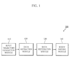
- FIG. 1 is a block diagram showing a robot motion data processing system (hereinafter, also referred to as a "data processing system") 100 according to an embodiment of the present disclosure.
- the data processing system 100 of this embodiment includes a data extraction module 120 for intermittently extracting restoration motion data from a successive input motion trajectory formed for controlling a motion of a robot, and a data restoration module 130 for restoring an output motion trajectory approximate to the input motion trajectory by using restoration motion data extracted from the data extraction module 120.
- the data processing system 100 may further include an input trajectory generation module 110 for generating the input motion trajectory, and a robot driving module 140 for driving the robot according to the output motion trajectory generated from the data restoration module 130.
- the input trajectory generation module 110 may generate a successive input motion trajectory by collecting successive motion information of a human or a master robot ("master”) or generate an input motion trajectory aiming at the motion of the robot by means of a trajectory generating algorithm.
- the input trajectory generation module 110 is not always necessary, and a user may directly design a successive input motion trajectory and input the same to the data extraction module 120.
- Successessive input motion trajectory does not always mean a seamless trajectory over the time, but if all data included in the corresponding trajectory are transmitted through a standard network, an aggregate of data may be included in the successive input motion trajectory if the data forming the trajectory have so little time interval not to substantially control the robot in real time.
- the robot motion data in the input motion trajectory may include position data for indicating a position of the robot and velocity data for indicating velocity of the robot at the position.
- the data extraction module 120 intermittently extracts restoration motion data from the input motion trajectory and transmits the restoration motion data to the data restoration module 130 through a network.
- the network may include either a wireless network or a wired network.
- the data restoration module 130 restores an output motion trajectory approximate to the input motion trajectory by using the restoration motion data extracted from the data extraction module 120.
- the output motion trajectory is restored to satisfy a condition that the robot operating according to the corresponding motion trajectory does not exceed a hardware operation limit of the robot.
- the "hardware operation limit of the robot” may be, for example, a driving limit such as a maximum velocity, a maximum acceleration, a maximum jerk or the like of the robot, a limit in controlled frequency of the robot, or a limit in size of the robot.
- the limit in controlled frequency of the robot and the limit in size of the robot may be relatively easily satisfied.
- restoration is performed only within a limit where the controlled frequency is satisfied, in consideration of time when a reduction signal is received.
- d max (explained later in detail) set during a data reduction process may be received, compared with current d max of the robot and then used as a scaling factor.
- driving limits such as velocity, acceleration, jerk or the like are used, more complicated methods are demanded, as explained later in detail.
- the robot driving module 140 drives the robot according to the output motion trajectory generated by the data restoration module 130.
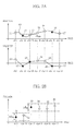
- FIGS. 2A and 2B are graphs for illustrating a motion data reduction method by using the data extraction module 120 according to an embodiment of the present disclosure.
- the data extraction module 120 extracts original motion data from an input motion trajectory 60 at every predetermined sampling time.
- the original motion data includes position data 11 to 17, which represent a position of the robot, and velocity data 21 to 27, which indicate a velocity of the robot.
- the data extraction module 120 may adjust a reduction rate according to a state of the network, and in a non-reduction mode where the reduction rate is 0, all of the original motion data may be transmitted to the data restoration module 130 as restoration motion data.
- the data extraction module 120 of this embodiment performs a reduction process by eliminating a part of the original motion data.
- the restoration motion data is a reduced data obtained by reducing the original motion data.
- a method for finding an anchor point representing minimal samples to maintain a signal characteristic of motion data and/or a so-called “dead band” method for selecting an error range to filter the data is used.
- the position data 11 to 17 of the original motion data are compared with previous data, and data at which the zero-crossing velocity occurs is determined as an anchor point.
- the motion data is discrete data, and thus it is substantially impossible to accurate a point with zero velocity all the time. Therefore, in this embodiment, the anchor point is defined as follows.
- the position data 12, the position data 13 and the position data 16 are data corresponding to the candidate anchor point.
- the candidate anchor point determined at this stage may be determined as an anchor point as it is, and the position data 12, the position data 13 and the position data 16 may be transmitted as restoration motion data to the data restoration module 130.
- the candidate anchor point is determined as above, if the signal value of the corresponding point stays within a given range (d min ) during a predetermined time, successive motion data during the time are also set as candidate anchor points regardless of zero-crossing. This is to consider a situation where a change of the velocity value is maintained in a slight level due to a numerical error or a small velocity value in spite of zero velocity.
- a new signal stays within a given range during t d time, all signals after that time are set as candidate anchor points. Meanwhile, a user may adjust the value ⁇ to determine the time after which signals are set as candidate anchor points. By doing so, a point where a stop state changes into an operating state may be estimated.
- the candidate anchor point obtained as above is spaced apart from the selected anchor point signal already confirmed as an anchor point over a predetermined distance, this is determined as a new selected anchor point.
- the equation y i +1 y a if
- ⁇ d min may be referred to, which is for applying a threshold value to eliminate neighboring points, and d min may be defined by the user.
- states where operation and stop are repeated due to signal noise or very small motion may be filtered off, thereby eliminating unnecessary signals.
- the position data 12, 16 may become respectively data corresponding to the selected anchor point.
- the position data 12, 16 corresponding to the selected anchor point are transmitted as restoration motion data to the data restoration module 130.
- FIG. 2B a method for selecting restoration motion data by reducing original motion data at p, p+1, p+3, p+4, and p+5 time by means of a dead band is schematically illustrated.
- FIG. 2B uses a label different from FIG. 2A (in other words, p is used instead of k).
- a motion data 31 to be transmitted as restoration motion data is confirmed, it is determined based on the motion data 31 whether a distance variance of successive motion data 32 with respect to the motion data 31 is within a predetermined error range ( ⁇ th ). Since the motion data 32 is within the error range ( ⁇ th ), the motion data 32 is not included in the restoration motion data.
- the above determination is repeated to successive motion data, and if a motion data 33 having a distance variance with respect to the motion data 31 beyond the error range ( ⁇ th ) appears, the corresponding motion data is included in the restoration motion data.
- ⁇ represents a threshold value which defines the error range
- ⁇ is a value between 0 and 1 which is defined by the user
- d max represents a maximum length of the robot.
- the user may set d max which represents a maximum value of the signal.
- d max may be determined as a specific hardware value such as a maximum length of the arm of the robot.
- a maximum difference between the original signal and the reduced signal namely a maximum error, may be controlled by adjusting the reduction rate, and thus when setting the reduction rate, the user may estimate the degree of error of the reduced signal in advance.
- the present disclosure allows normalization by d max , and thus consistent reduction is ensured regardless of the signal size.
- the anchor point method and the dead band method may be alternately applied to reduce original motion data.
- FIG. 3 is a flowchart for illustrating an original motion data reduction method according to an embodiment of the present disclosure
- the motion data reduction method may embrace from S110 for obtaining original motion data to S150 for transmitting reduced data.
- the data extraction module 120 obtains original motion data by means of a sensor or another interface device.
- the data extraction module 120 extracts a selected anchor point from the obtained original motion data.
- the data extraction module 120 performs reduction by using a dead band.
- the data extraction module 120 determines whether the compression parameter ( ⁇ ) is 1. If the compression parameter is 1, a maximum reduction rate is applied, and motion data corresponding to the selected anchor point extracted in the above step is transmitted as restoration motion data to the data restoration module 130 (the process proceeds to S150).
- the data extraction module 120 additionally extract data other than the selected anchor point from the original motion data, based on an error range ( ⁇ th ) determined according to a compression parameter.
- the data extraction module 120 determines whether a distance variance of successive data is within the error range, based on a recent selected anchor point. Points indicated by the successive motion data do not have great variances from the selected anchor point and are likely not to give an importance influence on the control of the robot, and thus they are excluded when selecting the restoration motion data. Meanwhile, if variances of the points are beyond the threshold value based on the selected anchor point, these points have great variances from the selected anchor point and are highly likely to give an important influence on the control of the robot. Therefore, motion data representing these points are extracted as restoration motion data.
- the data extraction module 120 transmits the motion data corresponding to the selected anchor point and the motion data newly extracted by the dead band method to the data restoration module 130 as restoration motion data.
- the restoration motion data reduced from the original motion data by the data extraction module 120 are data obtained by omitting many intermediate data from the original motion data in order to reduce data amount to be transmitted and transmission frequency. Therefore, it is actually not easy to control the robot by using only the received restoration motion data, and the intermediate data are interpolated based on the restoration motion data to generate an output motion trajectory approximate to the input motion trajectory in order to control operations of the actual robot.
- a plurality of interpolation data may be inserted among the received reduced data by means of a zero-order-hold method or a linear prediction method to perform restoration.
- the interpolated intermediate data are not data directly received from the data extraction module 120 but data interpolated by means of prediction, which may have an error in comparison to the actual original motion data.
- error may be accumulated as time goes, and when a new restoration motion data is received afterwards, an interval between the previously interpolated data and a new restoration motion data may be seriously great due to the accumulated error.
- the motion data of the robot is controlled to rapidly track the new restoration motion data, a motion according to the control may exceed a physical limit of the robot, which may damage the robot. Therefore, in the present disclosure, in this case, the motion data is restored by using a restoration method which considers hardware limits of the robot between a restoration motion data and data on the output motion trajectory already restored.
- the data restoration module 130 of this embodiment interpolates the restoration motion data to generate an output motion trajectory while satisfying the condition that the restored signal does not exceed physical limits of the robot, for example hardware operation limit of the robot such as velocity, acceleration, jerk or the like.
- This restoration method may use a polynomial.
- a method using a polynomial demands an optimization process in order to consider hardware limits of the robot, which may consume a lot of time in data restoration. Therefore, the method using a polynomial may be more advantageous in a system having a high-performance processor.
- a restoration method using convolution is used.
- FIG. 4 is a graph for illustrating the concept of the data restoration method according to an embodiment of the present disclosure.
- first data (y i ) indicated by a reference number 41 is a currently restored position data and second data (y i+1 ) indicated by a reference number 42 is a restoration motion data which is a newly received position data.
- first data (y i ) and the second data (y i+1 ) may be respectively a current velocity data and a newly received velocity data.
- the data restoration module 130 During a motion data restoring process, the data restoration module 130 generates an output motion trajectory to move the robot from a current position (y i ) to a new position (y i+1 ), and convolution-interpolated data may be inserted among position data (y i , y i+1 ) so that the generated output motion trajectory does not exceed a maximum velocity, a maximum acceleration and a maximum jerk of the robot.
- the data restoration module 130 since the robot is not able to move directly from the current position (y i ) to the new position (y i+1 ) due to the limits of a maximum velocity, a maximum acceleration and a maximum jerk, the data restoration module 130 generates an output motion trajectory 43, which the robot may actually track, by means of convolution interpolation.
- FIGS. 5A to 5C are diagrams for illustrating a convolution interpolation method used for motion trajectory restoration/generation according to an embodiment of the present disclosure.
- the convolution interpolation method may advantageously generate differentiable trajectories successively without departing from physical limits of the robot.
- This convolution interpolation method may be performed by repeatedly applying convolution several times.
- FIG. 5A is a diagram for illustrating a first convolution of the convolution interpolation method according to this embodiment.
- an initial velocity and an initial position are respectively assumed to be 0.
- the output motion trajectory of the robot is generated as a trajectory y 0 (t).
- the trajectory y 0 (t) is continuous but not differentiable, and thus if actual hardware conditions of the robot are taken into consideration, the robot is not able to track the original trajectory y 0 (t) as it is.
- the original trajectory y 0 (t) is converted into a first trajectory y 1 (t).
- the original trajectory y 1 (t) is generated more softly in comparison to the first trajectory y 0 (t). This is because physical limits of the robot are reflected.
- the used convolution function is a convolution function h 1 (t) which is a rectangular wave function of a unit area.
- Equation 2 the convolution is defined as Equation 2 below.
- Trajectories generated through convolution (for example, the first trajectory y 1 (t)) have the following attributes.
- the convolution process may be repeatedly performed to generate a longer trajectory having a gentler duration.
- a secondary convolution is performed to the trajectory y 1 (t) obtained through the first convolution to generate a secondary trajectory y 2 (t).
- the generated trajectory y 2 (t) is gentler than the first trajectory y 1 (t) but has a duration
- k [t/T s]
- m n [t n /T s ]
- T s represents a sampling period
- [x] means a gauss floor function
- a gentler trajectory may be generated by repeating convolution (see FIG. 5C ).
- the repetition frequency of convolution is not limited, and if it is impossible or inadequate for the robot to track a trajectory generated through convolution without change, the convolution may be suitably repeated to solve this problem.
- the user may determine the repetition frequency of convolution in advance, and the convolution is repeatedly performed as much as the predetermined frequency. As described above, if the frequency of convolution increases, a generated trajectory becomes gentler, and the possibility of deviating physical limits of the robot decreases. However, in this case, the time of reaching a final control position is delayed more.
- a duration (t k ) in a k th convolution function at a k th convolution is defined as in Equation 4 below.
- v max k means a system limit of the robot with regard to the k th convolution.
- v max 0 , v max 1 , v max 2 respectively represent a maximum velocity, a maximum acceleration and a maximum jerk of the robot.
- the motion data may be restored by reflecting physical limits of maximum velocity, acceleration and jerk of a driving unit which drives the robot.
- a maximum error namely a maximum error, between the signal restored according to the method described above and the original signal is similar to that set during a reducing process.
- the maximum error is not identical since a signal is not able to be restored identical to the original signal due to a numerical error or the nature of the interpolation method during the restoring process.
- the numerical error or the error caused by interpolation is limited within a predetermined range, the maximum error of the restored signal does not greatly deviate from the maximum error set during the reducing process but has a similar range thereto.
- time is discrete, and thus if the time is smaller than the sampling period (T s ), the time is set to be 0.
- a distance error (e) smaller than a value obtained by multiplying the sampling period (T s ) by the initial velocity (v 0 ) is not processed by the convolution method (a resolution error).
- the maximum resolution error (e max ) is generated when the initial velocity is the maximum velocity of the robot, and this resolution error may be solved by forcibly setting the initial time (to) to be identical to the sampling period (T s ) and calculating the initial velocity (v 0 ) according to a linear prediction method.
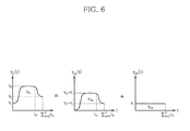
- FIG. 6 is a diagram for illustrating the convolution interpolation method when the initial velocity is not 0.
- the initial velocity of the original trajectory is v i
- the final velocity is v f (but, v i ⁇ 0, v f ⁇ 0).
- the restoration function is divided into a portion (y na (t)) where the initial velocity is 0 and a rectangular wave function portion (y nb (t)) where the initial velocity is not 0.
- the convolution is applied to each portion in the same way as illustrated in FIG. 5 , and then its result is added thereto to obtain an overall convolution result.
- This convolution process may be expressed like Equation 5 below.
- the output motion trajectory is restored from the restoration motion data by using the convolution method described above.
- FIG. 7 is a graph for illustrating a high-speed data restoration/generation method in which a real-time characteristic is emphasized, according to an embodiment of the present disclosure.
- the data restoration module 130 if receiving the first restoration motion data (y i ) from the data extraction module 120, the data restoration module 130 generates an estimated trajectory 51 by interpolating the trajectory by using a general restoration method such as a zero-order-hold method or a linear prediction method, based on the first restoration motion data, and then if successive second restoration motion data (y i+1 ) is received, the data restoration module 130 performs convolution interpolation based on the current motion data (r i (n)) of the robot indicated by the estimated trajectory 51 and the second restoration motion data, thereby generating a tracking trajectory 52 which tracks the second restoration motion data.
- a general restoration method such as a zero-order-hold method or a linear prediction method
- an output motion trajectory 50 connecting from the estimated trajectory 51 to the tracking trajectory 52 is generated in real time.
- the velocity (v i ) may be set to be 0 and be any velocity smaller than the available maximum velocity of the robot, or be velocity data of the robot included in the first restoration motion data.
- the data restoration module 130 generates the output motion trajectory in a way of generating trajectory data (r i (1), r i (2),.., r i (n)) at every constant restoring sampling time (T s ) until a new restoration motion data is received.
- the interpolated motion data (r i (1), r i (2),.., r i (n)) are estimated values, which may have an error from the actual original motion data 60.
- a target position (y i+1 ) (and, a target velocity (v f )) included in the data is detected, and convolution is performed based on the estimated previous restoration data (r i (n)) and the second restoration motion data so that the robot may track the target position (y i+1 ) and the target velocity (v f ) without exceeding the physical limit.
- the restoration data (r i (n)) includes a position of the robot indicated by the estimated trajectory 51 and is estimated in a restoration sampling period just before the second restoration motion data is input.
- a distance (S d ) between the position of the robot indicated by the restoration data (r i (n)) and the position (yi+1) of the robot indicated by the second restoration motion data is used as an area of the original restoration function (for example, So of y 0 (t) in FIG. 5 ), the original restoration function having an initial velocity of v i and a final velocity of v f is set, and then convolution is performed thereto according to the method illustrated in FIG. 5 or FIG. 6 at least once to generate a tracking trajectory 52.
- the robot may move to the position indicated by the second restoration motion data within a range where the tracking trajectory does not exceed the maximum velocity, the maximum acceleration and the maximum jerk of the robot.
- the robot further moves with the velocity (v f ) while the original motion data is being tracked according to the convolution (in FIG. 7 , moves further as much as y i+1 -r i+1 (k)).
- the tracking trajectory 52 is generated to track an estimated motion data (r i+1 (k)), which estimates a motion of the robot after a predetermined time from the point when the second restoration motion data is received, based on the second restoration motion data.
- the information of the estimated motion data (r i+1 (k)), which indicates the position of the robot after a predetermined time (t f ) from a sampling time when the restoration data (r i (n)) is generated, may be predicted.
- convolution is performed to a restoration function having a distance (S k ) between a position of the robot at the restoration data (r i (n)) and a position of the robot indicated by the estimated motion data (r i+1 (k)) as an area, instead of the distance (S d ) between the position of the robot at the restoration data (r i (n)) and the position (y i+1 ) of the robot indicated by the second restoration motion data, at least once to generate a tracking trajectory.
- the area (S k ) of the restoration function may be calculated by Equation 6 below.
- W o max represents an available maximum velocity of the robot
- time (t o ) for performing convolution once may be calculated by Equation 7 below.
- the velocity (v f ) of the robot indicated by the second restoration motion data extracted from the original motion data may exceed the available maximum velocity (w o max ) of the robot.
- the estimated motion data (r i+1 (k)) may not be tracked, and in this case, the tracking trajectory 52 is generated to track the second restoration motion data with the maximum operation limit of the robot after a predetermined time delay.
- convolution is performed to a restoration function having a distance (S d ) between a position of the robot indicated by the restoration data (r i (n)) at the end point of the estimated trajectory and a position of the robot indicated by the estimated motion data (r i+1 (k)) at least once to generate a tracking trajectory.
- the area (S d ) of the restoration function may be calculated by Equation 8 below.
- w o max represents an available maximum velocity of the robot
- time (t o ) for performing convolution once may be calculated by Equation 9 below.
- the tracking trajectory may be generated without exceeding the maximum operation limit of the robot.
- FIG. 8 is a graph for illustrating a precise data restoration method, in which error minimization and accuracy are emphasized, according to another embodiment of the present disclosure.
- FIG. 8 a restoration method for minimizing an error of an original motion data even though a trajectory has a somewhat slow restoration velocity will be described.
- the restoration module 120 performs restoration based on convolution after waiting until at least two restoration motion data are received.
- a first restoration motion data is received at a time t i and a second restoration motion data is received at a time t i+1 .
- the data restoration module 130 does not perform restoration in a time region between t i and t i+1 , and generates a tracking trajectory 62 at the t i+1 time when at least two restoration motion data are completely received.
- an estimated trajectory is not present, and the tracking trajectory 62 serves as an output motion trajectory.
- the trajectory designated by the reference number 61 is an input motion trajectory.
- the tracking trajectory 62 connecting from the first restoration motion data (y i , v i ) to the second restoration motion data (y i+1 , v f ) is generated, the restoration is performed based on convolution so that the robot does not exceed its hardware physical limits even though the robot operates according to the generated tracking trajectory 62.
- a distance (S k ) between a position (y i ) of the robot indicated by the restoration motion data 53 and a position (y i+1 ) of the robot indicated by the second restoration motion data 54 is used as an area of the restoration function (for example, So of y 0 (t) in FIG. 5 ), and the tracking trajectory 62 is generated by performing convolution according to the methods as described above by setting the restoration function having an initial velocity of v i and a final velocity of v f .
- the method is executed slowly in comparison to the high-speed restoration method of FIG. 7 .
- the time (t f ) at which two restoration motion data are received is sufficiently short or a network is not good, the original motion data does not have a great error in comparison to the extracted input motion trajectory 61 since the trajectory is restored based on two definitive restoration motion data.
- FIGS. 9A and 9B are graphs showing simulation results of a motion data processing system according to embodiments of the present disclosure.
- FIG. 9A shows a simulation result when the robot has relatively good hardware performance
- FIG. 9B shows a simulation result when the robot has relatively bad hardware performance.
- a first graph 1 depicts an input motion trajectory
- a second graph 2 depicts a restoration motion data reduced and transmitted according to the data reduction method of this embodiment
- a third graph 3 depicts an output motion trajectory restored according to this embodiment.
- the robot has good hardware performance, available velocity, acceleration and jerk limits of the robot are higher, and thus the trajectory-tracing velocity exhibits relatively more excellent tracking performance. Meanwhile, if the robot has bad hardware performance, available velocity, acceleration and jerk limits of the robot are lower, and thus a greater error occurs between the restored trajectory and the original trajectory.
- the data since reduced data is automatically restored compatible to the performance of the robot, the data may be used regardless of the hardware performance of the robot.
- stable control is ensured since data continuity is ensured up to a level designated by a user, and an error from the original data may be predicted during a reducing or restoring process, thereby ensuring precise control.
Landscapes
- Engineering & Computer Science (AREA)
- Robotics (AREA)
- Mechanical Engineering (AREA)
- Manipulator (AREA)
- Numerical Control (AREA)
Abstract
Description
- The present disclosure relates to a robot motion data processing system, and more particularly, to a robot motion data processing system for processing motion data, generated for operating a robot, in consideration of hardware limits.
- As robots are used in more fields, a "smart robot" is being developed to perform highly-developed operations in more diverse environments, without being limited to an industrial robot having a simple workspace and simple operation patterns.
- The smart robot is, for example, a robot (slave) which imitates a motion of a human (master) as it is.
- A motion of a human is performed continuously along a trajectory and thus may be expressed as a successive motion trajectory.
- In order to allow the slave to imitate a motion of the master most similarly, data about the successive motion trajectory of the master should be split as small as possible and then transmitted to the slave over as numerous times as possible. It is known that data should be transmitted at least 100 times per second in order to obtain real-time synchronization between a source and a target.
- In other words, in case of robot motion data for controlling a robot, an amount of information included therein is small but transmission frequency should be high, different from general sound/image data.
- For real-time robot control, it is a main technical issue how frequently data can be transmitted per unit time.
- This may be satisfied to some extent if a rapid network with excellent performance is constructed. However, there is a limit in aspect of communication technology and hardware in enhancing a transmission velocity of a network.
- For this reason, a study for compressing data to reduce an amount or transmission frequency of the robot motion data is being made to realize real-time control.
- However, a data restoring method compatible for characteristics of a target, which is a robot operating according to a successive trajectory, has not been proposed so much.
- The present disclosure is directed to providing a motion data processing system compatible for a control target, namely a robot.
- In one aspect, there is provided a robot motion data processing system, which includes: a data extraction module for intermittently extracting restoration motion data from a successive input motion trajectory formed for controlling a motion of a robot; and a data restoration module for restoring an output motion trajectory approximate to the input motion trajectory by using restoration motion data extracted from the data extraction module. The output motion trajectory is restored to satisfy a condition that the robot operating according to the output motion trajectory does not exceed a hardware operation limit of the robot.
- According to an embodiment, the data restoration module may be configured to: generate an estimated trajectory estimated based on a received first restoration motion data; and when a second restoration motion data is received in succession to the first restoration motion data, generate a tracking trajectory, which tracks the second restoration motion data, based on the second restoration motion data and a current robot motion data indicated by an end point of the estimated trajectory, thereby generating the output motion trajectory connecting from the estimated trajectory to the tracking trajectory in real time.
- According to an embodiment, the tracking trajectory may be generated to track estimated motion data, which estimates a motion of the robot after a predetermined time from a point when the second restoration motion data is received, based on the second restoration motion data.
- According to an embodiment, when it is determined that the robot does not trace the estimated motion data even though the robot is operated up to a maximum operation limit, the tracking trajectory may be generated to trace the second restoration motion data with a predetermined time delay within the maximum operation limit of the robot.
- According to an embodiment, the tracking trajectory may be generated by performing convolution at least once to a restoration function having a distance between a position of the robot indicated by the end point of the estimated trajectory and a position of the robot indicated by the second restoration motion data as an area with a rectangular wave function having an area of 1.
- According to an embodiment, the tracking trajectory may be generated by performing convolution at least once to a restoration function having a distance between a position of the robot indicated by the end point of the estimated trajectory and a position of the robot indicated by the estimated motion data as an area with a rectangular wave function having an area of 1.
- According to an embodiment, after receiving a first restoration motion data and also receiving a second restoration motion data in succession to the first restoration motion data, the data restoration module may generate a tracking trajectory, which tracks the second restoration motion data, based on the first restoration motion data and the second restoration motion data.
- According to an embodiment, the tracking trajectory may be generated by performing convolution at least once to a restoration function having a distance between a position of the robot indicated by the first restoration motion data and a position of the robot indicated by the second restoration motion data as an area with a rectangular wave function having an area of 1.
- According to an embodiment, the data extraction module may extract an original motion data from the input motion trajectory at every predetermined sampling time, and extract the restoration motion data through a reducing process in which a partial data is eliminated from the original motion data.
- According to an embodiment, the data extraction module may be configured to compare the original motion data with the previous data to determine data at which the zero-crossing velocity occurs as an anchor point, and transmit motion data corresponding to the anchor point to the data restoration module as the restoration motion data.
- According to an embodiment, the original motion data may be compared with previous data to determine data at which the zero-crossing velocity occurs as a candidate anchor point, and when the position of the robot indicated by the two candidate anchor points is spaced apart from the position of the robot indicated by the selected anchor point already confirmed as the restoration motion data to be transmitted over a predetermined distance range, the corresponding candidate anchor point may be determined as a new selected anchor point and transmitted to the data restoration module as restoration motion data corresponding to the selected anchor point.
- According to an embodiment, the data extraction module may determine motion data, which are located in the predetermined distance range during a predetermined time, among the original motion data in succession to the determined candidate anchor point as candidate anchor points regardless of the zero-crossing.
- According to an embodiment, the data extraction module may be configured to: set a predetermined error range; and compare motion data in succession to the selected anchor point among the original motion data with the selected anchor point, and when a distance variance is beyond the error range, transmit the corresponding motion data as restoration motion data to the data restoration module.
- According to an embodiment, the data extraction module may adjust the error range to control a reduction rate of the original motion data.
- According to an embodiment, the data extraction module may transmit the selected anchor point as restoration motion data to the data restoration module in a maximum reduction mode.
-
-
FIG. 1 is a block diagram showing a motion data processing system showing a robot according to an embodiment of the present disclosure. -
FIGS. 2A and 2B are graphs for illustrating a motion data reduction method according to an embodiment of the present disclosure. -
FIG. 3 is a flowchart for illustrating a motion data reduction method according to an embodiment of the present disclosure. -
FIG. 4 is a graph showing a summary of a data restoration/generation method according to an embodiment of the present disclosure. -
FIGS. 5A to 5C and6 are diagrams for illustrating a convolution interpolation method used for data restoration/generation according to an embodiment of the present disclosure. -
FIG. 7 is a graph for illustrating a high-speed data restoration/generation method according to an embodiment of the present disclosure. -
FIG. 8 is a graph for illustrating a precise data restoration/generation method according to another embodiment of the present disclosure. -
FIGS. 9A and 9B are graphs showing simulation results of a reduction/restoration system according to embodiments of the present disclosure. - Hereinafter, embodiments of the present disclosure will be described in detail with reference to the accompanying drawings. Even though the present disclosure is described with reference to an embodiment depicted in the drawings, this is just an example, and the essential configuration and operations of the present disclosure are not limited thereto.
-
FIG. 1 is a block diagram showing a robot motion data processing system (hereinafter, also referred to as a "data processing system") 100 according to an embodiment of the present disclosure. - Referring to
FIG. 1 , thedata processing system 100 of this embodiment includes adata extraction module 120 for intermittently extracting restoration motion data from a successive input motion trajectory formed for controlling a motion of a robot, and adata restoration module 130 for restoring an output motion trajectory approximate to the input motion trajectory by using restoration motion data extracted from thedata extraction module 120. - The
data processing system 100 may further include an inputtrajectory generation module 110 for generating the input motion trajectory, and arobot driving module 140 for driving the robot according to the output motion trajectory generated from thedata restoration module 130. - The input
trajectory generation module 110 may generate a successive input motion trajectory by collecting successive motion information of a human or a master robot ("master") or generate an input motion trajectory aiming at the motion of the robot by means of a trajectory generating algorithm. - The input
trajectory generation module 110 is not always necessary, and a user may directly design a successive input motion trajectory and input the same to thedata extraction module 120. - In this specification, the term "successive input motion trajectory" does not always mean a seamless trajectory over the time, but if all data included in the corresponding trajectory are transmitted through a standard network, an aggregate of data may be included in the successive input motion trajectory if the data forming the trajectory have so little time interval not to substantially control the robot in real time.
- In this embodiment, the robot motion data in the input motion trajectory may include position data for indicating a position of the robot and velocity data for indicating velocity of the robot at the position.
- The
data extraction module 120 intermittently extracts restoration motion data from the input motion trajectory and transmits the restoration motion data to thedata restoration module 130 through a network. - The network may include either a wireless network or a wired network.
- The
data restoration module 130 restores an output motion trajectory approximate to the input motion trajectory by using the restoration motion data extracted from thedata extraction module 120. - In this embodiment, the output motion trajectory is restored to satisfy a condition that the robot operating according to the corresponding motion trajectory does not exceed a hardware operation limit of the robot.
- Here, the "hardware operation limit of the robot" may be, for example, a driving limit such as a maximum velocity, a maximum acceleration, a maximum jerk or the like of the robot, a limit in controlled frequency of the robot, or a limit in size of the robot.
- The limit in controlled frequency of the robot and the limit in size of the robot may be relatively easily satisfied. For example, in case of the limit in controlled frequency, restoration is performed only within a limit where the controlled frequency is satisfied, in consideration of time when a reduction signal is received. Regarding the limit in size of the robot, dmax (explained later in detail) set during a data reduction process may be received, compared with current dmax of the robot and then used as a scaling factor. Meanwhile, when driving limits such as velocity, acceleration, jerk or the like are used, more complicated methods are demanded, as explained later in detail.
- The
robot driving module 140 drives the robot according to the output motion trajectory generated by thedata restoration module 130. - Now, a data processing method of the
data extraction module 120 and thedata restoration module 130 will be described in detail with reference to the accompanying drawings. -
FIGS. 2A and 2B are graphs for illustrating a motion data reduction method by using thedata extraction module 120 according to an embodiment of the present disclosure. - As shown in
FIG. 2A , thedata extraction module 120 extracts original motion data from aninput motion trajectory 60 at every predetermined sampling time. - The original motion data includes
position data 11 to 17, which represent a position of the robot, andvelocity data 21 to 27, which indicate a velocity of the robot. - The
data extraction module 120 may adjust a reduction rate according to a state of the network, and in a non-reduction mode where the reduction rate is 0, all of the original motion data may be transmitted to thedata restoration module 130 as restoration motion data. - However, in order to decrease the amount and frequency of data transmission, the
data extraction module 120 of this embodiment performs a reduction process by eliminating a part of the original motion data. In this embodiment, the restoration motion data is a reduced data obtained by reducing the original motion data. - In this embodiment, for the data reduction, a method for finding an anchor point representing minimal samples to maintain a signal characteristic of motion data and/or a so-called "dead band" method for selecting an error range to filter the data is used.
- First, the method for finding an anchor point will be described. In this embodiment, the
position data 11 to 17 of the original motion data are compared with previous data, and data at which the zero-crossing velocity occurs is determined as an anchor point. - In more detail, in a digital signal system, the motion data is discrete data, and thus it is substantially impossible to accurate a point with zero velocity all the time. Therefore, in this embodiment, the anchor point is defined as follows.
- First, if the equation v(k)·v(k-1)≤ 0 is satisfied, since a point where a current velocity of the data is 0 is passed, the data at that time is assumed as a signal where velocity is 0, and this is determined as a candidate anchor point which is to be determined as the anchor point. In this method, it is possible to estimate a direction change or stop of the robot.
- Referring to
FIG. 2A , theposition data 12, theposition data 13 and theposition data 16 are data corresponding to the candidate anchor point. - The candidate anchor point determined at this stage may be determined as an anchor point as it is, and the
position data 12, theposition data 13 and theposition data 16 may be transmitted as restoration motion data to thedata restoration module 130. - However, in this embodiment, even though the actual velocity is 0, a time condition for confirming the anchor point is added in order to consider a situation where a change of the velocity value is insignificant due to a numerical error or a small velocity value.
- After the candidate anchor point is determined as above, if the signal value of the corresponding point stays within a given range (dmin) during a predetermined time, successive motion data during the time are also set as candidate anchor points regardless of zero-crossing. This is to consider a situation where a change of the velocity value is maintained in a slight level due to a numerical error or a small velocity value in spite of zero velocity. At this time, the equation td = ξ/Ts may be referred to, where 0 ≤ ξ ≤ 1, and Ts represents a sampling time at which one signal is received. For example, 1/Ts may be the number of data generated during 1 second. Therefore, if a new signal stays within a given range during td time, all signals after that time are set as candidate anchor points. Meanwhile, a user may adjust the value ζ to determine the time after which signals are set as candidate anchor points. By doing so, a point where a stop state changes into an operating state may be estimated.
- Subsequently, if the candidate anchor point obtained as above is spaced apart from the selected anchor point signal already confirmed as an anchor point over a predetermined distance, this is determined as a new selected anchor point. At this time, the equation y i+1 = ya if |ya - yi |≥ d minmay be referred to, which is for applying a threshold value to eliminate neighboring points, and dmin may be defined by the user. In this method, states where operation and stop are repeated due to signal noise or very small motion may be filtered off, thereby eliminating unnecessary signals.
- For example, in
FIG. 2A , theposition data position data data restoration module 130. - Hereinafter, a method for reducing original motion data by means of a dead band will be described.
- In the reduction method using an anchor point described above, minimal samples are found to maintain a characteristic of an operation signal. However, in the reduction method using a dead band, signals are transmitted only when other signals are beyond the threshold value.
- Referring to
FIG. 2B , a method for selecting restoration motion data by reducing original motion data at p, p+1, p+3, p+4, and p+5 time by means of a dead band is schematically illustrated. - For generalized explanation,
FIG. 2B uses a label different fromFIG. 2A (in other words, p is used instead of k). - If a
motion data 31 to be transmitted as restoration motion data is confirmed, it is determined based on themotion data 31 whether a distance variance ofsuccessive motion data 32 with respect to themotion data 31 is within a predetermined error range (±δth). Since themotion data 32 is within the error range (±δth), themotion data 32 is not included in the restoration motion data. - The above determination is repeated to successive motion data, and if a
motion data 33 having a distance variance with respect to themotion data 31 beyond the error range (±δth) appears, the corresponding motion data is included in the restoration motion data. - After that, based on the
motion data 33 which is a new restoration motion data, it is determined whether successive data are within the error range (±δth). - In this embodiment, the error range is defined according to
Equation 1.
- Here, δ represents a threshold value which defines the error range, γ is a value between 0 and 1 which is defined by the user, and dmax represents a maximum length of the robot. Meanwhile, if γ is 0, this means that the restoration motion data is identical to the original motion data, and in this case, reduction is not performed at all. Meanwhile, if γ is 1, this means maximum reduction.
- In this method, while maintaining basic characteristics of an operation signal by using the anchor point, it is possible to automatically or manually select a reduction rate between maximum reduction and non-reduction by adjusting the γ value. In an embodiment, in order to adjust the range of γ value, the user may set dmax which represents a maximum value of the signal. dmax may be determined as a specific hardware value such as a maximum length of the arm of the robot. As described above, a maximum difference between the original signal and the reduced signal, namely a maximum error, may be controlled by adjusting the reduction rate, and thus when setting the reduction rate, the user may estimate the degree of error of the reduced signal in advance.
- In this method, the present disclosure allows normalization by dmax, and thus consistent reduction is ensured regardless of the signal size.
- In this embodiment, in order to enhance the reduction efficiency, the anchor point method and the dead band method may be alternately applied to reduce original motion data.
-
FIG. 3 is a flowchart for illustrating an original motion data reduction method according to an embodiment of the present disclosure - Referring to
FIG. 3 , the motion data reduction method may embrace from S110 for obtaining original motion data to S150 for transmitting reduced data. - In
S 110, thedata extraction module 120 obtains original motion data by means of a sensor or another interface device. - In S120, the
data extraction module 120 extracts a selected anchor point from the obtained original motion data. - In S130, the
data extraction module 120 performs reduction by using a dead band. In detail, thedata extraction module 120 determines whether the compression parameter (γ) is 1. If the compression parameter is 1, a maximum reduction rate is applied, and motion data corresponding to the selected anchor point extracted in the above step is transmitted as restoration motion data to the data restoration module 130 (the process proceeds to S150). - Meanwhile, if the compression parameter is not 1, the process proceeds to
S 140 to additionally extract restoration motion data. - In S140, the
data extraction module 120 additionally extract data other than the selected anchor point from the original motion data, based on an error range (±δth) determined according to a compression parameter. - In detail, the
data extraction module 120 determines whether a distance variance of successive data is within the error range, based on a recent selected anchor point. Points indicated by the successive motion data do not have great variances from the selected anchor point and are likely not to give an importance influence on the control of the robot, and thus they are excluded when selecting the restoration motion data. Meanwhile, if variances of the points are beyond the threshold value based on the selected anchor point, these points have great variances from the selected anchor point and are highly likely to give an important influence on the control of the robot. Therefore, motion data representing these points are extracted as restoration motion data. - In S150, the
data extraction module 120 transmits the motion data corresponding to the selected anchor point and the motion data newly extracted by the dead band method to thedata restoration module 130 as restoration motion data. - According to the motion data reduction method as above, it is possible to extract and transmit just far fewer data as reduced data, in comparison to the data reducing method based on human perception proposed in the
non-patent literature 1. - The restoration motion data reduced from the original motion data by the
data extraction module 120 are data obtained by omitting many intermediate data from the original motion data in order to reduce data amount to be transmitted and transmission frequency. Therefore, it is actually not easy to control the robot by using only the received restoration motion data, and the intermediate data are interpolated based on the restoration motion data to generate an output motion trajectory approximate to the input motion trajectory in order to control operations of the actual robot. - For example, according to a sampling period of the original motion data, a plurality of interpolation data may be inserted among the received reduced data by means of a zero-order-hold method or a linear prediction method to perform restoration.
- In this case, the interpolated intermediate data are not data directly received from the
data extraction module 120 but data interpolated by means of prediction, which may have an error in comparison to the actual original motion data. Such error may be accumulated as time goes, and when a new restoration motion data is received afterwards, an interval between the previously interpolated data and a new restoration motion data may be seriously great due to the accumulated error. In this case, if the motion data of the robot is controlled to rapidly track the new restoration motion data, a motion according to the control may exceed a physical limit of the robot, which may damage the robot. Therefore, in the present disclosure, in this case, the motion data is restored by using a restoration method which considers hardware limits of the robot between a restoration motion data and data on the output motion trajectory already restored. - In detail, the
data restoration module 130 of this embodiment interpolates the restoration motion data to generate an output motion trajectory while satisfying the condition that the restored signal does not exceed physical limits of the robot, for example hardware operation limit of the robot such as velocity, acceleration, jerk or the like. - This restoration method may use a polynomial. However, a method using a polynomial demands an optimization process in order to consider hardware limits of the robot, which may consume a lot of time in data restoration. Therefore, the method using a polynomial may be more advantageous in a system having a high-performance processor.
- In order to ensure easy restoration in a system with low performance, in this embodiment, a restoration method using convolution is used.
-
FIG. 4 is a graph for illustrating the concept of the data restoration method according to an embodiment of the present disclosure. - First, it is assumed that first data (yi) indicated by a
reference number 41 is a currently restored position data and second data (yi+1) indicated by areference number 42 is a restoration motion data which is a newly received position data. However, this is just an example, and the first data (yi) and the second data (yi+1) may be respectively a current velocity data and a newly received velocity data. During a motion data restoring process, thedata restoration module 130 generates an output motion trajectory to move the robot from a current position (yi) to a new position (yi+1), and convolution-interpolated data may be inserted among position data (yi, yi+1) so that the generated output motion trajectory does not exceed a maximum velocity, a maximum acceleration and a maximum jerk of the robot. - In other words, since the robot is not able to move directly from the current position (yi) to the new position (yi+1) due to the limits of a maximum velocity, a maximum acceleration and a maximum jerk, the
data restoration module 130 generates anoutput motion trajectory 43, which the robot may actually track, by means of convolution interpolation. - The convolution interpolation method and a motion trajectory generated by the method will be described in more detail later with reference to
FIGS. 5A to 5C . -
FIGS. 5A to 5C are diagrams for illustrating a convolution interpolation method used for motion trajectory restoration/generation according to an embodiment of the present disclosure. - The convolution interpolation method may advantageously generate differentiable trajectories successively without departing from physical limits of the robot. This convolution interpolation method may be performed by repeatedly applying convolution several times.
-
FIG. 5A is a diagram for illustrating a first convolution of the convolution interpolation method according to this embodiment. InFIG. 5A , an initial velocity and an initial position are respectively assumed to be 0. - If the input restoration motion data designates that the robot has a position of So and a velocity at that time is designated as vo, the output motion trajectory of the robot is generated as a trajectory y0(t). At this time, the trajectory y0(t) is continuous but not differentiable, and thus if actual hardware conditions of the robot are taken into consideration, the robot is not able to track the original trajectory y0(t) as it is.
- Therefore, by means of the first convolution, the original trajectory y0(t) is converted into a first trajectory y1(t). As shown in
FIG. 5A , the original trajectory y1(t) is generated more softly in comparison to the first trajectory y0(t). This is because physical limits of the robot are reflected. At this time, the used convolution function is a convolution function h1(t) which is a rectangular wave function of a unit area. - Generally, the convolution is defined as
Equation 2 below.
- Trajectories generated through convolution (for example, the first trajectory y1(t)) have the following attributes.
- 1) Even though the first trajectory y1(t) is gentler than the original trajectory y0(t), the first trajectory y1(t) has a duration (t1+t1) as much as the sum of durations of the original trajectory y0(t) and the convolution function h1(t).
- 2) The first trajectory y1(t) has the same area as the original trajectory y0(t) (S0-S1).
- 3) The maximum size of the first trajectory y1(t) is equal to or smaller than the maximum size of the original trajectory y0(t) (v0 ≥ v1).
- Meanwhile, the convolution process may be repeatedly performed to generate a longer trajectory having a gentler duration.
- In
FIG. 5B , a secondary convolution is performed to the trajectory y1(t) obtained through the first convolution to generate a secondary trajectory y2(t). The generated trajectory y2(t) is gentler than the first trajectory y1(t) but has a duration - (t0+t1+t2) as much as the sum of the duration of the first trajectory y1(t) and the duration of the secondary convolution function h2(t). Meanwhile, similar to the case of the first trajectory y1(t) above, the secondary trajectory y2(t) also has the same area as the first trajectory y1(t) (S0=S1=S2), and the maximum size of the secondary trajectory y2(t) is equal to or smaller than the maximum size of the first trajectory y1(t) (v0 ≥ v1 ≥ v2).
- Such a form where discrete representations of convolution are repeated may be expressed as
Equation 3 below.
- However, k=[t/Ts], mn=[tn/Ts], where Ts represents a sampling period, and [x] means a gauss floor function.
- By using the above method, a gentler trajectory may be generated by repeating convolution (see
FIG. 5C ). The repetition frequency of convolution is not limited, and if it is impossible or inadequate for the robot to track a trajectory generated through convolution without change, the convolution may be suitably repeated to solve this problem. In other case, the user may determine the repetition frequency of convolution in advance, and the convolution is repeatedly performed as much as the predetermined frequency. As described above, if the frequency of convolution increases, a generated trajectory becomes gentler, and the possibility of deviating physical limits of the robot decreases. However, in this case, the time of reaching a final control position is delayed more. - Meanwhile, the
data restoration module 130 of this embodiment sets a parameter of the convolution function, used in the convolution process, in consideration of physical limits of the robot. In detail, referring toFIGS. 5A to 5C , a duration (tk) in a kth convolution function at a kth convolution is defined as inEquation 4 below.
- Here,


- According to the motion data restoration method based on convolution as described above, the motion data may be restored by reflecting physical limits of maximum velocity, acceleration and jerk of a driving unit which drives the robot. A maximum error, namely a maximum error, between the signal restored according to the method described above and the original signal is similar to that set during a reducing process. The maximum error is not identical since a signal is not able to be restored identical to the original signal due to a numerical error or the nature of the interpolation method during the restoring process. However, since the numerical error or the error caused by interpolation is limited within a predetermined range, the maximum error of the restored signal does not greatly deviate from the maximum error set during the reducing process but has a similar range thereto.
- Meanwhile, in the convolution method described above, time is discrete, and thus if the time is smaller than the sampling period (Ts), the time is set to be 0. In other words, a distance error (e) smaller than a value obtained by multiplying the sampling period (Ts) by the initial velocity (v0) is not processed by the convolution method (a resolution error). The maximum resolution error (emax) is generated when the initial velocity is the maximum velocity of the robot, and this resolution error may be solved by forcibly setting the initial time (to) to be identical to the sampling period (Ts) and calculating the initial velocity (v0) according to a linear prediction method.
-
FIG. 6 is a diagram for illustrating the convolution interpolation method when the initial velocity is not 0. InFIG. 6 , the initial velocity of the original trajectory is vi, and the final velocity is vf (but, vi ≠0, vf≠0). - In this case, the restoration function is divided into a portion (yna(t)) where the initial velocity is 0 and a rectangular wave function portion (ynb(t)) where the initial velocity is not 0. In addition, the convolution is applied to each portion in the same way as illustrated in
FIG. 5 , and then its result is added thereto to obtain an overall convolution result. - This convolution process may be expressed like
Equation 5 below.
- In this embodiment, the output motion trajectory is restored from the restoration motion data by using the convolution method described above.
-
FIG. 7 is a graph for illustrating a high-speed data restoration/generation method in which a real-time characteristic is emphasized, according to an embodiment of the present disclosure. - Referring to
FIG. 7 , for real-time high-speed data restoration, if receiving the first restoration motion data (yi) from thedata extraction module 120, thedata restoration module 130 generates an estimatedtrajectory 51 by interpolating the trajectory by using a general restoration method such as a zero-order-hold method or a linear prediction method, based on the first restoration motion data, and then if successive second restoration motion data (yi+1) is received, thedata restoration module 130 performs convolution interpolation based on the current motion data (ri(n)) of the robot indicated by the estimatedtrajectory 51 and the second restoration motion data, thereby generating a trackingtrajectory 52 which tracks the second restoration motion data. - Accordingly, an
output motion trajectory 50 connecting from the estimatedtrajectory 51 to the trackingtrajectory 52 is generated in real time. - For example, it is assumed that the first restoration motion data is received and the target position and the target velocity of the robot at that time are respectively yi, vi. At this time, the
data restoration module 130 restores the motion data of the robot at every predetermined sampling period by using any one of general restoration methods. For example, if the motion data of the robot is restored by means of the linear prediction method, the restored motion data will have a position of yi at t=0 and become a trajectory which proceeds with a velocity of vi. - At this time, the velocity (vi) may be set to be 0 and be any velocity smaller than the available maximum velocity of the robot, or be velocity data of the robot included in the first restoration motion data.
- The
data restoration module 130 generates the output motion trajectory in a way of generating trajectory data (ri(1), ri(2),.., ri(n)) at every constant restoring sampling time (Ts) until a new restoration motion data is received. At this time, the interpolated motion data (ri(1), ri(2),.., ri(n)) are estimated values, which may have an error from the actualoriginal motion data 60. - If the second restoration motion data is received, a target position (yi+1) (and, a target velocity (vf)) included in the data is detected, and convolution is performed based on the estimated previous restoration data (ri(n)) and the second restoration motion data so that the robot may track the target position (yi+1) and the target velocity (vf) without exceeding the physical limit.
- The restoration data (ri(n)) includes a position of the robot indicated by the estimated
trajectory 51 and is estimated in a restoration sampling period just before the second restoration motion data is input. - In detail, a distance (Sd) between the position of the robot indicated by the restoration data (ri(n)) and the position (yi+1) of the robot indicated by the second restoration motion data is used as an area of the original restoration function (for example, So of y0(t) in
FIG. 5 ), the original restoration function having an initial velocity of vi and a final velocity of vf is set, and then convolution is performed thereto according to the method illustrated inFIG. 5 orFIG. 6 at least once to generate a trackingtrajectory 52. - If convolution is performed at least three times to generate the tracking
trajectory 52, the robot may move to the position indicated by the second restoration motion data within a range where the tracking trajectory does not exceed the maximum velocity, the maximum acceleration and the maximum jerk of the robot. - However, if the final velocity (vf) of the robot is not 0 at the point when the second restoration motion data is input, the robot further moves with the velocity (vf) while the original motion data is being tracked according to the convolution (in
FIG. 7 , moves further as much as yi+1-ri+1(k)). - In order to compensate such an additional movement, in this embodiment, the tracking
trajectory 52 is generated to track an estimated motion data (ri+1(k)), which estimates a motion of the robot after a predetermined time from the point when the second restoration motion data is received, based on the second restoration motion data. - Since the position (yi+1) and the velocity (vf) of the robot at the point when the second restoration motion data is received are already known, the information of the estimated motion data (ri+1(k)), which indicates the position of the robot after a predetermined time (tf) from a sampling time when the restoration data (ri(n)) is generated, may be predicted.
- In detail, convolution is performed to a restoration function having a distance (Sk) between a position of the robot at the restoration data (ri(n)) and a position of the robot indicated by the estimated motion data (ri+1(k)) as an area, instead of the distance (Sd) between the position of the robot at the restoration data (ri(n)) and the position (yi+1) of the robot indicated by the second restoration motion data, at least once to generate a tracking trajectory.
- At this time, the area (Sk) of the restoration function may be calculated by
Equation 6 below.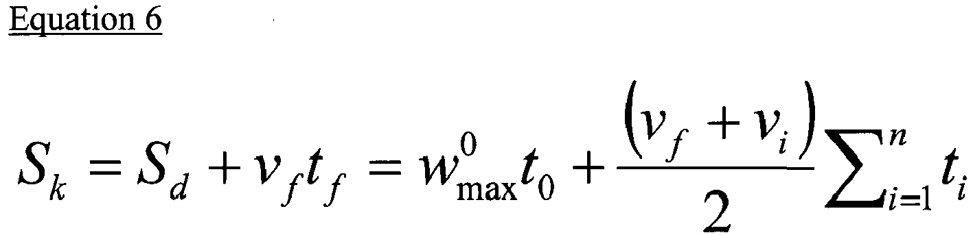
- Here, Wo max represents an available maximum velocity of the robot, and time (to) for performing convolution once may be calculated by Equation 7 below.

- Meanwhile, the velocity (vf) of the robot indicated by the second restoration motion data extracted from the original motion data may exceed the available maximum velocity (wo max) of the robot.
- In this case, even though the robot is operated up to the maximum operation limit, the estimated motion data (ri+1(k)) may not be tracked, and in this case, the tracking
trajectory 52 is generated to track the second restoration motion data with the maximum operation limit of the robot after a predetermined time delay. - In other words, convolution is performed to a restoration function having a distance (Sd) between a position of the robot indicated by the restoration data (ri(n)) at the end point of the estimated trajectory and a position of the robot indicated by the estimated motion data (ri+1(k)) at least once to generate a tracking trajectory.
- At this time, the area (Sd) of the restoration function may be calculated by Equation 8 below.

- Here, wo max represents an available maximum velocity of the robot, and time (to) for performing convolution once may be calculated by Equation 9 below.

- In this embodiment, even though there may be a little time delay in tracking the second restoration motion data, the tracking trajectory may be generated without exceeding the maximum operation limit of the robot.
- Heretofore, an embodiment for high-speed data restoration in which a real-time characteristic is emphasized has been described. In this embodiment, even though an error is generated between the estimated
trajectory 51 restored in an estimated range and theinput motion trajectory 60, if a new restoration motion data is received, the motion data of the robot is instantly corrected to track the original motion data, so as not to deviate physical limits of the robot. - In addition, since motion data is instantly estimated and generated whenever restoration motion data is received, an output motion trajectory may be restored and generated very rapidly to control the robot.
- Meanwhile,
FIG. 8 is a graph for illustrating a precise data restoration method, in which error minimization and accuracy are emphasized, according to another embodiment of the present disclosure. - In
FIG. 8 , a restoration method for minimizing an error of an original motion data even though a trajectory has a somewhat slow restoration velocity will be described. - In the method of
FIG. 8 , therestoration module 120 performs restoration based on convolution after waiting until at least two restoration motion data are received. - For example, it is assumed that a first restoration motion data is received at a time ti and a second restoration motion data is received at a time ti+1. In this case, the
data restoration module 130 does not perform restoration in a time region between ti and ti+1, and generates a trackingtrajectory 62 at the ti+1 time when at least two restoration motion data are completely received. - In this embodiment, an estimated trajectory is not present, and the tracking
trajectory 62 serves as an output motion trajectory. The trajectory designated by thereference number 61 is an input motion trajectory. - At this time, in order to track the
trajectory 61 of the original motion data, the trackingtrajectory 62 connecting from the first restoration motion data (yi, vi) to the second restoration motion data (yi+1, vf) is generated, the restoration is performed based on convolution so that the robot does not exceed its hardware physical limits even though the robot operates according to the generated trackingtrajectory 62. - In
FIG. 8 , a distance (Sk) between a position (yi) of the robot indicated by therestoration motion data 53 and a position (yi+1) of the robot indicated by the secondrestoration motion data 54 is used as an area of the restoration function (for example, So of y0(t) inFIG. 5 ), and the trackingtrajectory 62 is generated by performing convolution according to the methods as described above by setting the restoration function having an initial velocity of vi and a final velocity of vf. - According to the restoration method illustrated in
FIG. 8 , since the trajectory restoration is initiated after the second restoration motion data are received, the method is executed slowly in comparison to the high-speed restoration method ofFIG. 7 . However, if the time (tf) at which two restoration motion data are received is sufficiently short or a network is not good, the original motion data does not have a great error in comparison to the extractedinput motion trajectory 61 since the trajectory is restored based on two definitive restoration motion data. -
FIGS. 9A and 9B are graphs showing simulation results of a motion data processing system according to embodiments of the present disclosure. -
FIG. 9A shows a simulation result when the robot has relatively good hardware performance, andFIG. 9B shows a simulation result when the robot has relatively bad hardware performance. - In
FIGS. 9A and 9B , afirst graph 1 depicts an input motion trajectory, asecond graph 2 depicts a restoration motion data reduced and transmitted according to the data reduction method of this embodiment, and athird graph 3 depicts an output motion trajectory restored according to this embodiment. - If the robot has good hardware performance, available velocity, acceleration and jerk limits of the robot are higher, and thus the trajectory-tracing velocity exhibits relatively more excellent tracking performance. Meanwhile, if the robot has bad hardware performance, available velocity, acceleration and jerk limits of the robot are lower, and thus a greater error occurs between the restored trajectory and the original trajectory.
- However, regardless of the hardware performance, an
output motion trajectory 3 is restored in consideration of physical hardware limits of the robot, and thus it may be found that stability is ensured in aspect of control. - In the motion data processing system of this embodiment, since reduced data is automatically restored compatible to the performance of the robot, the data may be used regardless of the hardware performance of the robot. In addition, stable control is ensured since data continuity is ensured up to a level designated by a user, and an error from the original data may be predicted during a reducing or restoring process, thereby ensuring precise control.
Claims (15)
- A robot motion data processing system, comprising:a data extraction module (120) for intermittently extracting restoration motion data from a successive input motion trajectory formed for controlling a motion of a robot; anda data restoration module (130) for restoring an output motion trajectory approximate to the input motion trajectory by using restoration motion data extracted from the data extraction module,wherein the output motion trajectory is restored to satisfy a condition that the robot operating according to the output motion trajectory does not exceed a hardware operation limit of the robot.
- The robot motion data processing system according to claim 1, wherein the data restoration module (120) is configured to:generate an estimated trajectory estimated based on a received first restoration motion data; andwhen a second restoration motion data is received in succession to the first restoration motion data, generate a tracking trajectory, which tracks the second restoration motion data, based on the second restoration motion data and a current robot motion data indicated by an end point of the estimated trajectory,thereby generating the output motion trajectory connecting from the estimated trajectory to the tracking trajectory in real time.
- The robot motion data processing system according to claim 2,
wherein the tracking trajectory is generated to track estimated motion data, which estimates a motion of the robot after a predetermined time from a point when the second restoration motion data is received, based on the second restoration motion data. - The robot motion data processing system according to claim 3,
wherein when it is determined that the robot does not trace the estimated motion data even though the robot is operated up to a maximum operation limit, the tracking trajectory is generated to trace the second restoration motion data with a predetermined time delay within the maximum operation limit of the robot. - The robot motion data processing system according to claim 2,
wherein the tracking trajectory is generated by performing convolution at least once to a restoration function having a distance between a position of the robot indicated by the end point of the estimated trajectory and a position of the robot indicated by the second restoration motion data as an area with a rectangular wave function having an area of 1. - The robot motion data processing system according to claim 3,
wherein the tracking trajectory is generated by performing convolution at least once to a restoration function having a distance between a position of the robot indicated by the end point of the estimated trajectory and a position of the robot indicated by the estimated motion data as an area with a rectangular wave function having an area of 1. - The robot motion data processing system according to claim 1,
wherein, after receiving a first restoration motion data and also receiving a second restoration motion data in succession to the first restoration motion data, the data restoration module (120) generates a tracking trajectory, which tracks the second restoration motion data, based on the first restoration motion data and the second restoration motion data. - The robot motion data processing system according to claim 7,
wherein the tracking trajectory is generated by performing convolution at least once to a restoration function having a distance between a position of the robot indicated by the first restoration motion data and a position of the robot indicated by the second restoration motion data as an area with a rectangular wave function having an area of 1. - The robot motion data processing system according to one of claims 1 to 8,
wherein the data extraction module (130) extracts an original motion data from the input motion trajectory at every predetermined sampling time, and extracts the restoration motion data through a reducing process in which a partial data is eliminated from the original motion data. - The robot motion data processing system according to claim 9, wherein the data extraction module (130) is configured to:compare the original motion data with previous data to determine data at which the zero-crossing velocity occurs as an anchor point, and
transmit motion data corresponding to the anchor point to the data restoration module (120) as the restoration motion data. - The robot motion data processing system according to claim 10,
wherein the original motion data is compared with previous data to determine data at which the zero-crossing velocity occurs as a candidate anchor point, and wherein when the position of the robot indicated by the two candidate anchor points is spaced apart from the position of the robot indicated by the selected anchor point already confirmed as the restoration motion data to be transmitted over a predetermined distance range, the corresponding candidate anchor point is determined as a new selected anchor point and transmitted to the data restoration module (120) as restoration motion data corresponding to the selected anchor point. - The robot motion data processing system according to claim 11,
wherein the data extraction module (120) determines motion data, which are located in the predetermined distance range during a predetermined time, among the original motion data in succession to the determined candidate anchor point as candidate anchor points regardless of the zero-crossing. - The robot motion data processing system according to claim 12, wherein the data extraction module (130) is configured to:set a predetermined error range; andcompare motion data in succession to the selected anchor point among the original motion data with the selected anchor point, and when a distance variance is beyond the error range, transmit the corresponding motion data as restoration motion data to the data restoration module (120).
- The robot motion data processing system according to claim 13,
wherein the data extraction module (130) adjusts the error range to control a reduction rate of the original motion data. - The robot motion data processing system according to claim 14,
wherein the data extraction module (130) transmits the selected anchor point as restoration motion data to the data restoration module (120) in a maximum reduction mode.
Applications Claiming Priority (1)
| Application Number | Priority Date | Filing Date | Title |
|---|---|---|---|
| KR1020140108497A KR101661599B1 (en) | 2014-08-20 | 2014-08-20 | Robot motion data processing system using motion data reduction/restoration compatible to hardware limits |
Publications (3)
| Publication Number | Publication Date |
|---|---|
| EP2987591A2 true EP2987591A2 (en) | 2016-02-24 |
| EP2987591A3 EP2987591A3 (en) | 2016-09-14 |
| EP2987591B1 EP2987591B1 (en) | 2021-06-30 |
Family
ID=52345068
Family Applications (1)
| Application Number | Title | Priority Date | Filing Date |
|---|---|---|---|
| EP15150597.1A Active EP2987591B1 (en) | 2014-08-20 | 2015-01-09 | Robot motion data processing system using motion data reduction/restoration compatible to hardware limits |
Country Status (3)
| Country | Link |
|---|---|
| US (1) | US9561591B2 (en) |
| EP (1) | EP2987591B1 (en) |
| KR (1) | KR101661599B1 (en) |
Cited By (1)
| Publication number | Priority date | Publication date | Assignee | Title |
|---|---|---|---|---|
| CN109773787A (en) * | 2018-12-29 | 2019-05-21 | 南京埃斯顿机器人工程有限公司 | The Schistosomiasis control method of mechanical equipment and its server system for having learning functionality |
Families Citing this family (8)
| Publication number | Priority date | Publication date | Assignee | Title |
|---|---|---|---|---|
| JP6499273B2 (en) * | 2015-03-20 | 2019-04-10 | 株式会社Fuji | Teaching apparatus and control information generation method |
| JP6708581B2 (en) * | 2017-04-07 | 2020-06-10 | ライフロボティクス株式会社 | Teaching device, display device, teaching program and display program |
| CN109551479B (en) * | 2018-11-30 | 2021-09-14 | 长春工业大学 | Reconfigurable modular flexible mechanical arm trajectory tracking control method based on parameter optimization |
| JP6721922B1 (en) * | 2019-04-23 | 2020-07-15 | Arithmer株式会社 | Designated data generation device, designated data generation method, and designated data generation program |
| EP4013573A1 (en) * | 2019-11-19 | 2022-06-22 | Google LLC | Optimization of motion paths of a robot using vision data |
| CN112847355B (en) * | 2020-12-31 | 2022-08-12 | 山东大学 | A DMP-based robot bolt screwing method and system |
| US20220326022A1 (en) * | 2021-04-07 | 2022-10-13 | Lsc Ecosystem Corporation | Speed-based trajectory reduction method and device for reducing trajectory data according to speeds of trajectory points |
| EP4326496A1 (en) * | 2021-05-25 | 2024-02-28 | Siemens Aktiengesellschaft | Auto-generation of path constraints for grasp stability |
Family Cites Families (10)
| Publication number | Priority date | Publication date | Assignee | Title |
|---|---|---|---|---|
| US5046022A (en) | 1988-03-10 | 1991-09-03 | The Regents Of The University Of Michigan | Tele-autonomous system and method employing time/position synchrony/desynchrony |
| KR940002206B1 (en) * | 1991-01-26 | 1994-03-19 | 삼성전자 주식회사 | Robot Trajectory Generation Method Using Convolution |
| KR101021470B1 (en) * | 2008-12-02 | 2011-03-15 | 주식회사 케이엠씨로보틱스 | Method and apparatus for generating robot motion data using image data |
| TW201031507A (en) | 2009-02-25 | 2010-09-01 | Micro Star Int Co Ltd | Control apparatus of a multi-axial joint and control method thereof |
| FR2960075B1 (en) * | 2010-05-14 | 2012-06-15 | Staubli Sa Ets | METHOD FOR CONTROLLING AN AUTOMATED WORKING CELL |
| WO2013035244A1 (en) * | 2011-09-06 | 2013-03-14 | パナソニック株式会社 | Robotic arm control device and control method, robot, control program and integrated electronic circuit |
| KR101330049B1 (en) | 2012-03-06 | 2013-11-18 | 한국기계연구원 | Postprocessing method of direct teaching trajectory in industrial robot |
| KR101390819B1 (en) * | 2013-04-26 | 2014-05-07 | 한국과학기술연구원 | System and method for generating trajectory of robot using convolution operation |
| RU2743044C1 (en) * | 2014-02-20 | 2021-02-12 | Марк ОЛЕЙНИК | Robotic kitchen system |
| US10518409B2 (en) * | 2014-09-02 | 2019-12-31 | Mark Oleynik | Robotic manipulation methods and systems for executing a domain-specific application in an instrumented environment with electronic minimanipulation libraries |
-
2014
- 2014-08-20 KR KR1020140108497A patent/KR101661599B1/en not_active Expired - Fee Related
- 2014-12-23 US US14/581,433 patent/US9561591B2/en not_active Expired - Fee Related
-
2015
- 2015-01-09 EP EP15150597.1A patent/EP2987591B1/en active Active
Non-Patent Citations (1)
| Title |
|---|
| None |
Cited By (1)
| Publication number | Priority date | Publication date | Assignee | Title |
|---|---|---|---|---|
| CN109773787A (en) * | 2018-12-29 | 2019-05-21 | 南京埃斯顿机器人工程有限公司 | The Schistosomiasis control method of mechanical equipment and its server system for having learning functionality |
Also Published As
| Publication number | Publication date |
|---|---|
| KR20160022659A (en) | 2016-03-02 |
| US20160052132A1 (en) | 2016-02-25 |
| EP2987591A3 (en) | 2016-09-14 |
| US9561591B2 (en) | 2017-02-07 |
| EP2987591B1 (en) | 2021-06-30 |
| KR101661599B1 (en) | 2016-10-04 |
Similar Documents
| Publication | Publication Date | Title |
|---|---|---|
| US9561591B2 (en) | Robot motion data processing system using motion data reduction/restoration compatible to hardware limits | |
| Steinbring et al. | Progressive Gaussian filtering using explicit likelihoods | |
| RU2015112126A (en) | DEVICE AND METHOD FOR PROVIDING AN INFORMED EVALUATION OF PROBABILITY AND PRESENCE OF MULTI-CHANNEL SPEECH | |
| CN103760556B (en) | Based on the multi-target cognitive tracking of centralized MIMO radar | |
| CN103674001B (en) | A kind of optical fibre gyro denoising method based on strengthening self-adaptation time-frequency method | |
| CN107263473A (en) | A kind of man-machine interaction method based on virtual reality | |
| KR20230115027A (en) | System and Method for Improving Indoor Positioning Accuracy of UWB and AMCL based Mobile Robot | |
| CN104318072B (en) | QKF-MMF (Quantitative Kalman Filtering-Multi Method Fusion) based multi-sensor quantitative fusion method | |
| DE102019106190A1 (en) | Decompression of ultrasonic signals that have been compressed by means of signal object classes | |
| EP3904998B1 (en) | Synchronous control device, synchronous control system, synchronous control method, and simulation device | |
| CN114488195B (en) | Blind area range detection method and device for automatic driving vehicle and electronic equipment | |
| US12596976B2 (en) | Operations management system and operations management method | |
| CN115469303A (en) | Cognitive biological radar method and device for detecting human body posture and vital signs | |
| JP2014211330A (en) | Target tracking device and target tracking method | |
| CN103259471B (en) | Method for driving stepping motor based on smooth self-adaptation | |
| CN103376444B (en) | Human behavior feature recognition method and device | |
| JP2017125749A (en) | Signal processing device, radar receiver, signal processing method, and program | |
| US20190190760A1 (en) | Method and Apparatus for Determining Peak Power, Peak-To-Average Power Ratio | |
| CN103914628B (en) | A kind of Space teleoperation system output state Forecasting Methodology | |
| JP6524371B1 (en) | Filtering device, sensor device, filtering method and program | |
| JP2021001759A (en) | Signal tracking device, signal tracking system, signal tracking program, and signal tracking method | |
| JP2017049082A (en) | Group tracking device, group tracking method and program | |
| KR101390819B1 (en) | System and method for generating trajectory of robot using convolution operation | |
| Masood et al. | An efficient algorithm for robust curve fitting using cubic Bezier curves | |
| CN115633306A (en) | A positioning correction method and device for multi-region UWB signals |
Legal Events
| Date | Code | Title | Description |
|---|---|---|---|
| PUAI | Public reference made under article 153(3) epc to a published international application that has entered the european phase |
Free format text: ORIGINAL CODE: 0009012 |
|
| 17P | Request for examination filed |
Effective date: 20150129 |
|
| AK | Designated contracting states |
Kind code of ref document: A2 Designated state(s): AL AT BE BG CH CY CZ DE DK EE ES FI FR GB GR HR HU IE IS IT LI LT LU LV MC MK MT NL NO PL PT RO RS SE SI SK SM TR |
|
| AX | Request for extension of the european patent |
Extension state: BA ME |
|
| PUAL | Search report despatched |
Free format text: ORIGINAL CODE: 0009013 |
|
| AK | Designated contracting states |
Kind code of ref document: A3 Designated state(s): AL AT BE BG CH CY CZ DE DK EE ES FI FR GB GR HR HU IE IS IT LI LT LU LV MC MK MT NL NO PL PT RO RS SE SI SK SM TR |
|
| AX | Request for extension of the european patent |
Extension state: BA ME |
|
| RIC1 | Information provided on ipc code assigned before grant |
Ipc: B25J 9/16 20060101AFI20160808BHEP Ipc: B25J 9/00 20060101ALI20160808BHEP |
|
| GRAP | Despatch of communication of intention to grant a patent |
Free format text: ORIGINAL CODE: EPIDOSNIGR1 |
|
| STAA | Information on the status of an ep patent application or granted ep patent |
Free format text: STATUS: GRANT OF PATENT IS INTENDED |
|
| INTG | Intention to grant announced |
Effective date: 20210115 |
|
| GRAS | Grant fee paid |
Free format text: ORIGINAL CODE: EPIDOSNIGR3 |
|
| GRAA | (expected) grant |
Free format text: ORIGINAL CODE: 0009210 |
|
| STAA | Information on the status of an ep patent application or granted ep patent |
Free format text: STATUS: THE PATENT HAS BEEN GRANTED |
|
| AK | Designated contracting states |
Kind code of ref document: B1 Designated state(s): AL AT BE BG CH CY CZ DE DK EE ES FI FR GB GR HR HU IE IS IT LI LT LU LV MC MK MT NL NO PL PT RO RS SE SI SK SM TR |
|
| REG | Reference to a national code |
Ref country code: CH Ref legal event code: EP |
|
| REG | Reference to a national code |
Ref country code: AT Ref legal event code: REF Ref document number: 1405916 Country of ref document: AT Kind code of ref document: T Effective date: 20210715 Ref country code: DE Ref legal event code: R096 Ref document number: 602015070788 Country of ref document: DE |
|
| REG | Reference to a national code |
Ref country code: IE Ref legal event code: FG4D |
|
| REG | Reference to a national code |
Ref country code: LT Ref legal event code: MG9D |
|
| PG25 | Lapsed in a contracting state [announced via postgrant information from national office to epo] |
Ref country code: HR Free format text: LAPSE BECAUSE OF FAILURE TO SUBMIT A TRANSLATION OF THE DESCRIPTION OR TO PAY THE FEE WITHIN THE PRESCRIBED TIME-LIMIT Effective date: 20210630 Ref country code: BG Free format text: LAPSE BECAUSE OF FAILURE TO SUBMIT A TRANSLATION OF THE DESCRIPTION OR TO PAY THE FEE WITHIN THE PRESCRIBED TIME-LIMIT Effective date: 20210930 Ref country code: FI Free format text: LAPSE BECAUSE OF FAILURE TO SUBMIT A TRANSLATION OF THE DESCRIPTION OR TO PAY THE FEE WITHIN THE PRESCRIBED TIME-LIMIT Effective date: 20210630 |
|
| REG | Reference to a national code |
Ref country code: NL Ref legal event code: MP Effective date: 20210630 |
|
| REG | Reference to a national code |
Ref country code: AT Ref legal event code: MK05 Ref document number: 1405916 Country of ref document: AT Kind code of ref document: T Effective date: 20210630 |
|
| PG25 | Lapsed in a contracting state [announced via postgrant information from national office to epo] |
Ref country code: LV Free format text: LAPSE BECAUSE OF FAILURE TO SUBMIT A TRANSLATION OF THE DESCRIPTION OR TO PAY THE FEE WITHIN THE PRESCRIBED TIME-LIMIT Effective date: 20210630 Ref country code: GR Free format text: LAPSE BECAUSE OF FAILURE TO SUBMIT A TRANSLATION OF THE DESCRIPTION OR TO PAY THE FEE WITHIN THE PRESCRIBED TIME-LIMIT Effective date: 20211001 Ref country code: SE Free format text: LAPSE BECAUSE OF FAILURE TO SUBMIT A TRANSLATION OF THE DESCRIPTION OR TO PAY THE FEE WITHIN THE PRESCRIBED TIME-LIMIT Effective date: 20210630 Ref country code: RS Free format text: LAPSE BECAUSE OF FAILURE TO SUBMIT A TRANSLATION OF THE DESCRIPTION OR TO PAY THE FEE WITHIN THE PRESCRIBED TIME-LIMIT Effective date: 20210630 Ref country code: NO Free format text: LAPSE BECAUSE OF FAILURE TO SUBMIT A TRANSLATION OF THE DESCRIPTION OR TO PAY THE FEE WITHIN THE PRESCRIBED TIME-LIMIT Effective date: 20210930 |
|
| PG25 | Lapsed in a contracting state [announced via postgrant information from national office to epo] |
Ref country code: SM Free format text: LAPSE BECAUSE OF FAILURE TO SUBMIT A TRANSLATION OF THE DESCRIPTION OR TO PAY THE FEE WITHIN THE PRESCRIBED TIME-LIMIT Effective date: 20210630 Ref country code: SK Free format text: LAPSE BECAUSE OF FAILURE TO SUBMIT A TRANSLATION OF THE DESCRIPTION OR TO PAY THE FEE WITHIN THE PRESCRIBED TIME-LIMIT Effective date: 20210630 Ref country code: EE Free format text: LAPSE BECAUSE OF FAILURE TO SUBMIT A TRANSLATION OF THE DESCRIPTION OR TO PAY THE FEE WITHIN THE PRESCRIBED TIME-LIMIT Effective date: 20210630 Ref country code: CZ Free format text: LAPSE BECAUSE OF FAILURE TO SUBMIT A TRANSLATION OF THE DESCRIPTION OR TO PAY THE FEE WITHIN THE PRESCRIBED TIME-LIMIT Effective date: 20210630 Ref country code: AT Free format text: LAPSE BECAUSE OF FAILURE TO SUBMIT A TRANSLATION OF THE DESCRIPTION OR TO PAY THE FEE WITHIN THE PRESCRIBED TIME-LIMIT Effective date: 20210630 Ref country code: ES Free format text: LAPSE BECAUSE OF FAILURE TO SUBMIT A TRANSLATION OF THE DESCRIPTION OR TO PAY THE FEE WITHIN THE PRESCRIBED TIME-LIMIT Effective date: 20210630 Ref country code: NL Free format text: LAPSE BECAUSE OF FAILURE TO SUBMIT A TRANSLATION OF THE DESCRIPTION OR TO PAY THE FEE WITHIN THE PRESCRIBED TIME-LIMIT Effective date: 20210630 Ref country code: PT Free format text: LAPSE BECAUSE OF FAILURE TO SUBMIT A TRANSLATION OF THE DESCRIPTION OR TO PAY THE FEE WITHIN THE PRESCRIBED TIME-LIMIT Effective date: 20211102 Ref country code: RO Free format text: LAPSE BECAUSE OF FAILURE TO SUBMIT A TRANSLATION OF THE DESCRIPTION OR TO PAY THE FEE WITHIN THE PRESCRIBED TIME-LIMIT Effective date: 20210630 |
|
| PG25 | Lapsed in a contracting state [announced via postgrant information from national office to epo] |
Ref country code: PL Free format text: LAPSE BECAUSE OF FAILURE TO SUBMIT A TRANSLATION OF THE DESCRIPTION OR TO PAY THE FEE WITHIN THE PRESCRIBED TIME-LIMIT Effective date: 20210630 |
|
| REG | Reference to a national code |
Ref country code: DE Ref legal event code: R097 Ref document number: 602015070788 Country of ref document: DE |
|
| PG25 | Lapsed in a contracting state [announced via postgrant information from national office to epo] |
Ref country code: DK Free format text: LAPSE BECAUSE OF FAILURE TO SUBMIT A TRANSLATION OF THE DESCRIPTION OR TO PAY THE FEE WITHIN THE PRESCRIBED TIME-LIMIT Effective date: 20210630 |
|
| PLBE | No opposition filed within time limit |
Free format text: ORIGINAL CODE: 0009261 |
|
| STAA | Information on the status of an ep patent application or granted ep patent |
Free format text: STATUS: NO OPPOSITION FILED WITHIN TIME LIMIT |
|
| PG25 | Lapsed in a contracting state [announced via postgrant information from national office to epo] |
Ref country code: AL Free format text: LAPSE BECAUSE OF FAILURE TO SUBMIT A TRANSLATION OF THE DESCRIPTION OR TO PAY THE FEE WITHIN THE PRESCRIBED TIME-LIMIT Effective date: 20210630 |
|
| 26N | No opposition filed |
Effective date: 20220331 |
|
| PG25 | Lapsed in a contracting state [announced via postgrant information from national office to epo] |
Ref country code: IT Free format text: LAPSE BECAUSE OF FAILURE TO SUBMIT A TRANSLATION OF THE DESCRIPTION OR TO PAY THE FEE WITHIN THE PRESCRIBED TIME-LIMIT Effective date: 20210630 |
|
| PG25 | Lapsed in a contracting state [announced via postgrant information from national office to epo] |
Ref country code: MC Free format text: LAPSE BECAUSE OF FAILURE TO SUBMIT A TRANSLATION OF THE DESCRIPTION OR TO PAY THE FEE WITHIN THE PRESCRIBED TIME-LIMIT Effective date: 20210630 |
|
| REG | Reference to a national code |
Ref country code: CH Ref legal event code: PL |
|
| REG | Reference to a national code |
Ref country code: BE Ref legal event code: MM Effective date: 20220131 |
|
| PG25 | Lapsed in a contracting state [announced via postgrant information from national office to epo] |
Ref country code: LU Free format text: LAPSE BECAUSE OF NON-PAYMENT OF DUE FEES Effective date: 20220109 |
|
| PG25 | Lapsed in a contracting state [announced via postgrant information from national office to epo] |
Ref country code: BE Free format text: LAPSE BECAUSE OF NON-PAYMENT OF DUE FEES Effective date: 20220131 |
|
| PG25 | Lapsed in a contracting state [announced via postgrant information from national office to epo] |
Ref country code: LI Free format text: LAPSE BECAUSE OF NON-PAYMENT OF DUE FEES Effective date: 20220131 Ref country code: CH Free format text: LAPSE BECAUSE OF NON-PAYMENT OF DUE FEES Effective date: 20220131 |
|
| PG25 | Lapsed in a contracting state [announced via postgrant information from national office to epo] |
Ref country code: IE Free format text: LAPSE BECAUSE OF NON-PAYMENT OF DUE FEES Effective date: 20220109 |
|
| PG25 | Lapsed in a contracting state [announced via postgrant information from national office to epo] |
Ref country code: LT Free format text: LAPSE BECAUSE OF FAILURE TO SUBMIT A TRANSLATION OF THE DESCRIPTION OR TO PAY THE FEE WITHIN THE PRESCRIBED TIME-LIMIT Effective date: 20210630 |
|
| PG25 | Lapsed in a contracting state [announced via postgrant information from national office to epo] |
Ref country code: HU Free format text: LAPSE BECAUSE OF FAILURE TO SUBMIT A TRANSLATION OF THE DESCRIPTION OR TO PAY THE FEE WITHIN THE PRESCRIBED TIME-LIMIT; INVALID AB INITIO Effective date: 20150109 |
|
| PG25 | Lapsed in a contracting state [announced via postgrant information from national office to epo] |
Ref country code: MK Free format text: LAPSE BECAUSE OF FAILURE TO SUBMIT A TRANSLATION OF THE DESCRIPTION OR TO PAY THE FEE WITHIN THE PRESCRIBED TIME-LIMIT Effective date: 20210630 Ref country code: CY Free format text: LAPSE BECAUSE OF FAILURE TO SUBMIT A TRANSLATION OF THE DESCRIPTION OR TO PAY THE FEE WITHIN THE PRESCRIBED TIME-LIMIT Effective date: 20210630 |
|
| PG25 | Lapsed in a contracting state [announced via postgrant information from national office to epo] |
Ref country code: TR Free format text: LAPSE BECAUSE OF FAILURE TO SUBMIT A TRANSLATION OF THE DESCRIPTION OR TO PAY THE FEE WITHIN THE PRESCRIBED TIME-LIMIT Effective date: 20210630 |
|
| PG25 | Lapsed in a contracting state [announced via postgrant information from national office to epo] |
Ref country code: MT Free format text: LAPSE BECAUSE OF FAILURE TO SUBMIT A TRANSLATION OF THE DESCRIPTION OR TO PAY THE FEE WITHIN THE PRESCRIBED TIME-LIMIT Effective date: 20210630 |
|
| PGFP | Annual fee paid to national office [announced via postgrant information from national office to epo] |
Ref country code: GB Payment date: 20241223 Year of fee payment: 11 |
|
| PGFP | Annual fee paid to national office [announced via postgrant information from national office to epo] |
Ref country code: FR Payment date: 20241224 Year of fee payment: 11 |
|
| PGFP | Annual fee paid to national office [announced via postgrant information from national office to epo] |
Ref country code: DE Payment date: 20241223 Year of fee payment: 11 |