EP2987570A1 - Component casting - Google Patents
Component casting Download PDFInfo
- Publication number
- EP2987570A1 EP2987570A1 EP15170445.9A EP15170445A EP2987570A1 EP 2987570 A1 EP2987570 A1 EP 2987570A1 EP 15170445 A EP15170445 A EP 15170445A EP 2987570 A1 EP2987570 A1 EP 2987570A1
- Authority
- EP
- European Patent Office
- Prior art keywords
- mould
- projections
- mould portion
- recesses
- tang
- Prior art date
- Legal status (The legal status is an assumption and is not a legal conclusion. Google has not performed a legal analysis and makes no representation as to the accuracy of the status listed.)
- Granted
Links
Images



Classifications
-
- B—PERFORMING OPERATIONS; TRANSPORTING
- B22—CASTING; POWDER METALLURGY
- B22D—CASTING OF METALS; CASTING OF OTHER SUBSTANCES BY THE SAME PROCESSES OR DEVICES
- B22D27/00—Treating the metal in the mould while it is molten or ductile ; Pressure or vacuum casting
- B22D27/04—Influencing the temperature of the metal, e.g. by heating or cooling the mould
- B22D27/045—Directionally solidified castings
-
- B—PERFORMING OPERATIONS; TRANSPORTING
- B22—CASTING; POWDER METALLURGY
- B22C—FOUNDRY MOULDING
- B22C9/00—Moulds or cores; Moulding processes
- B22C9/02—Sand moulds or like moulds for shaped castings
- B22C9/04—Use of lost patterns
-
- B—PERFORMING OPERATIONS; TRANSPORTING
- B22—CASTING; POWDER METALLURGY
- B22D—CASTING OF METALS; CASTING OF OTHER SUBSTANCES BY THE SAME PROCESSES OR DEVICES
- B22D25/00—Special casting characterised by the nature of the product
- B22D25/02—Special casting characterised by the nature of the product by its peculiarity of shape; of works of art
-
- B—PERFORMING OPERATIONS; TRANSPORTING
- B22—CASTING; POWDER METALLURGY
- B22D—CASTING OF METALS; CASTING OF OTHER SUBSTANCES BY THE SAME PROCESSES OR DEVICES
- B22D25/00—Special casting characterised by the nature of the product
- B22D25/06—Special casting characterised by the nature of the product by its physical properties
-
- F—MECHANICAL ENGINEERING; LIGHTING; HEATING; WEAPONS; BLASTING
- F01—MACHINES OR ENGINES IN GENERAL; ENGINE PLANTS IN GENERAL; STEAM ENGINES
- F01D—NON-POSITIVE DISPLACEMENT MACHINES OR ENGINES, e.g. STEAM TURBINES
- F01D5/00—Blades; Blade-carrying members; Heating, heat-insulating, cooling or antivibration means on the blades or the members
- F01D5/12—Blades
- F01D5/14—Form or construction
- F01D5/141—Shape, i.e. outer, aerodynamic form
-
- F—MECHANICAL ENGINEERING; LIGHTING; HEATING; WEAPONS; BLASTING
- F05—INDEXING SCHEMES RELATING TO ENGINES OR PUMPS IN VARIOUS SUBCLASSES OF CLASSES F01-F04
- F05D—INDEXING SCHEME FOR ASPECTS RELATING TO NON-POSITIVE-DISPLACEMENT MACHINES OR ENGINES, GAS-TURBINES OR JET-PROPULSION PLANTS
- F05D2220/00—Application
- F05D2220/30—Application in turbines
-
- F—MECHANICAL ENGINEERING; LIGHTING; HEATING; WEAPONS; BLASTING
- F05—INDEXING SCHEMES RELATING TO ENGINES OR PUMPS IN VARIOUS SUBCLASSES OF CLASSES F01-F04
- F05D—INDEXING SCHEME FOR ASPECTS RELATING TO NON-POSITIVE-DISPLACEMENT MACHINES OR ENGINES, GAS-TURBINES OR JET-PROPULSION PLANTS
- F05D2230/00—Manufacture
- F05D2230/20—Manufacture essentially without removing material
- F05D2230/21—Manufacture essentially without removing material by casting
-
- F—MECHANICAL ENGINEERING; LIGHTING; HEATING; WEAPONS; BLASTING
- F05—INDEXING SCHEMES RELATING TO ENGINES OR PUMPS IN VARIOUS SUBCLASSES OF CLASSES F01-F04
- F05D—INDEXING SCHEME FOR ASPECTS RELATING TO NON-POSITIVE-DISPLACEMENT MACHINES OR ENGINES, GAS-TURBINES OR JET-PROPULSION PLANTS
- F05D2260/00—Function
- F05D2260/20—Heat transfer, e.g. cooling
- F05D2260/221—Improvement of heat transfer
- F05D2260/2214—Improvement of heat transfer by increasing the heat transfer surface
- F05D2260/22141—Improvement of heat transfer by increasing the heat transfer surface using fins or ribs
Definitions
- the present invention relates to component casting and, more particularly to component casting of directional solidification or single crystal components for engines such as a turbine blade having a portion with a reduced cross-sectional area e.g. a tang portion.
- the investment casting process is used to create metal components, e.g. turbine blades, by pouring molten metal into a ceramic shell of the desired final shape and subsequently removing the ceramic shell.
- the process is an evolution of the lost-wax process whereby a component of the size and shape required in metal is manufactured using a wax pattern die into which molten wax is injected.
- the wax pattern is then dipped in ceramic slurry to create a ceramic shell on the wax pattern.
- the wax is removed and the shell fired to harden it.
- the resulting ceramic shell has an open cavity of the size and shape of the final component into which the metal can be poured.
- the ceramic shell is subsequently removed, either physically or chemically.
- a technique called directional solidification is used. This involves use of a spiral, "pig-tail" selector to initiate single crystal or grain growth followed by subsequent withdrawal of the mould (e.g. the ceramic shell) containing the cooling cast component from a heating zone into a cooling zone (having a chill plate) within a vacuum furnace at a predetermined rate such that the temperature gradient within the cast component is closely controlled.
- the mould e.g. the ceramic shell
- the cooling zone having a chill plate
- the "mushy zone” at the interface between the molten and solid metal in the cooling casting must be a calm (stagnant) interface with a flat temperature gradient in order to achieve a single crystal structure with no discontinuities.
- EP1452251-A1 It is known from EP1452251-A1 to provide a horizontally oriented, displaced radiation deflector element in a mould for component casting.
- the radiation deflector element acts to reduce heat transfer between downward facing surfaces of the cast component (above the portions having a reduced cross sectional area) and the chill plate in the cooling zone of the furnace during directional solidification by acting as a barrier between the heating and cooling zones and reflecting heat back into the downward facing surfaces in the heating zone. This helps control (increase) the temperature gradient across the "mushy zone” which, in turn, helps reduce defects in the single crystal component by reducing buoyancy-induced defects such as freckling, sliver grains or high angle grain boundaries.
- the present invention provides a mould for component casting using a directional solidification process, said mould comprising at least one mould portion defining a cavity with a reduced cross-sectional area which defines the shape of an element to be removed from the component in a subsequent manufacturing step, wherein said at least one mould portion comprises at least one recess which further reduces the cross-sectional area of the cavity and increases the surface area of the at least one mould portion or wherein said at least one mould portion comprises a plurality of projections which increase the surface area of the least one mould portion, such that, in use, the radiative heat loss from said at least one mould portion during said process is increased.
- the mould of the first aspect can be used in a method of component casting using a directional solidification process comprising forming a mould, the mould having at least one mould portion defining a cavity with a reduced cross-sectional area which defines the shape of an element to be removed from the component in a subsequent manufacturing step, wherein said at least one mould portion comprises at least one recess which further reduces the cross-sectional area of the cavity and increases the surface area of the at least one mould portion or wherein said at least one mould portion comprises a plurality of projections which increase the surface area of the least one mould portion thereby increasing radiative heat loss from said at least one mould portion during said process.
- the thermal mass of the portion of the cast component contained with the mould portion is reduced and the surface area of the mould portion is increased such that, during cooling of the cast component in the directional solidification process, the amount and rate of radiative heat loss from the mould portion in the cooling zone is increased.
- the surface area of the mould portion is increased such that, during cooling of the cast component in the directional solidification process, the amount and rate of radiative heat loss from the mould portion in the cooling zone is increased. This helps control (increase) the thermal gradient across the liquid/solid interface thus limiting defects in the single crystal structure of the component.
- the element defined by the at least one mould portion may be a tang which serves not only to provide improved control of the temperature gradient, but can be used to support the component in post casting machining or surface finishing operations.
- the tang can be removed from the component as a subsequent post casting step in the manufacture of the finished component.
- the or each recess is an elongated recess (or slot).
- the recesses may be a series of elongated recesses (or slots) separated by one or more interspaced elongated ribs on the mould portion.
- the plurality of projections may be a series of elongated projections, e.g. elongated projecting ribs on the mould portion.
- the interspaced elongated rib(s) or plurality of projections/elongated projecting ribs may have a semi-circular-, square- (optionally with rounded vertices), triangular-, trapezoidal-, or dovetail-shaped cross section (at 90 degrees to the direction of elongation).
- the cross-section shape and/or cross-sectional area may vary along the length of the or each rib.
- the interspaced elongated rib(s) or plurality of projections/elongated projecting ribs may each have a through channel or bore to further increase the surface area of the mould portion.
- the recess, recesses and interspaced rib(s) or at least one of said plurality of projections/elongated projecting ribs may be zig-zagged.
- the or each recess may be branched with the branches at least partly surrounding a protrusion on the mould portion.
- At least one of the plurality of projections/elongated projecting ribs may be branched.
- the elongated recess(es) or slot(s) or the plurality of projections/elongated projecting ribs is/are vertically aligned on the mould portion i.e. aligned with or parallel to the major axis of the mould. This major axis will be aligned with the vertical direction of withdrawal of the mould from the heating zone and aligned with the axis of the pig-tail selector.
- the radiation of heat from the increased surface area is predominantly towards the walls of the cooling zone rather than the chill plate (which is typically provided at the end face of the cooling zone (towards which the mould is withdrawn during the directional solidification process)).
- the increased surface area of the mould portion faces the walls of the cooling zone rather than the chill plate i.e. there is an increased view factor towards the walls of the cooling zone rather than (downwards) towards the chill plate.
- the elongated recess(es) or slot(s) or the plurality of projections/elongated projecting ribs are aligned at an angle to the major axis of the mould.
- they may be transversely aligned on the mould portion (i.e. at 90 degrees to the major axis of the mould) or they may be angled at angle less than 90 degrees, e.g. 45 degrees on the mould portion.
- the or each recess or at least one of the plurality of projections may be a shaped recess/projection e.g. circular-, ovular-, diamond- or dog-bone-shaped recess/projection.
- a series of these shaped recesses may be provided and the series of recesses or the plurality of projections may be parallel to and/or transversely aligned with the major axis of the mould portion.
- the mould portion may have a posterior and anterior surface and the recess or series of recesses or plurality of projections/elongated projecting ribs as described above may be provided on one or both of said surfaces.
- the posterior and anterior surfaces may be separated by at least one side surface.
- the or each recess or each of said plurality of projections/elongated projecting ribs on the anterior and/or posterior surface may terminate before the side surface i.e. the recess or each recess/projection/projecting rib may be entirely contained within the respective surface.
- the recess or each recess/projection/projecting rib may extend into said at least one side surface.
- the mould may be for casting of a turbine blade and the mould may comprise a main body defining a cavity for forming a blade body.
- the mould portion defining the cavity with a reduced cross-sectional area may be for forming a tang portion of the turbine blade.
- the present invention provides a method for casting a turbine blade using a directional solidification process comprising forming a mould, the mould having a main body defining a cavity corresponding in shape to a blade body and at least one mould portion defining a cavity with a reduced cross-sectional area corresponding in shape to a tang portion, wherein said at least one mould portion comprises at least one recess which further reduces the cross sectional area of the tang portion cavity and increases the surface area of the at least one mould portion or wherein said at least one mould portion comprises a plurality of projections which increase the surface area of the least one mould portion thereby increasing radiative heat loss from said at least one mould portion during said process.
- the present invention provides a mould for casting a turbine blade using a directional solidification process, said mould comprising a main body defining a cavity corresponding in shape to a blade body and at least one mould portion defining a cavity with a reduced cross-sectional area corresponding in shape to a tang portion, wherein said at least one mould portion comprises at least one recess which further reduces the cross sectional area of the tang portion cavity and increases the surface area of the at least one mould portion or wherein said at least one mould portion comprises a plurality of projections which increase the surface area of the least one mould portion, such that, in use, the radiative heat loss from said at least one mould portion during said process is increased.
- the mould portion comprising at least one recess or a plurality of projections is as described with reference to the first and second aspects.
- the mould comprises two axially opposed mould portions defining cavities of reduced cross-sectional area corresponding in shape to the axially opposed tang portions.
- One mould portion defining the tang portion cavity will be located between the main body and a selector portion, the selector portion defining a cavity corresponding to the shape of the pig-tail selector.
- the anterior and posterior surfaces of the mould portion(s) defining the tang cavity/cavities may each have a tip which is trapezoid shaped (with the longest of the two parallel edges located proximal the main body of the mould).
- the angle of the two sloped edges may be between 50 and 70 degrees (preferably around 60 degrees) to the vertical (where the vertical is at 90 degrees to the parallel edges).
- the present invention provides a turbine blade formed according to the method of the first aspect and using a mould according to the second aspect.
- the tang portion(s) are clipped from the blade body.
- the present invention provides a turbine blade having a blade body and at least one tang portion having an anterior and posterior surface where at least one of said surfaces comprises at least one recess or wherein said at least one of said surfaces comprises a plurality of projections.
- the recessed tang has been found to retain its rigidity allowing its continued use for supporting the cast blade body during processing but with reduced metal content thus saving raw material costs during manufacturing.
- the turbine blade has two axially opposed recessed tang portions.
- the anterior and/or posterior surface(s) of the tang portion(s) will include the recess(es)/plurality of projections/elongated projecting ribs described above for the mould portion of the first and second aspects (since the anterior/posterior surfaces of the mould portion(s) will define the anterior/posterior surfaces of the tang portions).
- the tips of the anterior and posterior surfaces of the tang portion(s) may be trapezoid shaped (with the longest of the two parallel edges located proximal the blade body).
- the angle of the two sloped edges may be between 50 and 70 degrees to the vertical (where the vertical is at 90 degrees to the parallel edges).
- the present invention provides a turbine for a gas turbine engine, the turbine comprising a plurality of turbine blades according to the fifth or sixth aspect.
- the present invention provides a gas turbine engine having a turbine according to the seventh aspect.
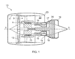
- a ducted fan gas turbine engine incorporating a series of turbines each having a plurality of aerofoil blades formed using a method according to an embodiment of the present invention is generally indicated at 10 and has a principal and rotational axis X-X.
- the engine comprises, in axial flow series, an air intake 11, the propulsive fan 12, an intermediate pressure compressor 13, a high-pressure compressor 14, combustion equipment 15, a high-pressure turbine 16, an intermediate pressure turbine 17, a low-pressure turbine 18 and a core engine exhaust nozzle 19.
- a nacelle 21 generally surrounds the engine 10 and defines the intake 11, a bypass duct 22 and a bypass exhaust nozzle 23.
- air entering the intake 11 is accelerated by the fan 12 to produce two air flows: a first air flow A into the intermediate pressure compressor 13 and a second air flow B which passes through the bypass duct 22 to provide propulsive thrust.
- the intermediate pressure compressor 13 compresses the air flow A directed into it before delivering that air to the high pressure compressor 14 where further compression takes place.
- the compressed air exhausted from the high-pressure compressor 14 is directed into the combustion equipment 15 where it is mixed with fuel and the mixture combusted.
- the resultant hot combustion products then expand through, and thereby drive the high, intermediate and low-pressure turbines 16, 17, 18 before being exhausted through the nozzle 19 to provide additional propulsive thrust.
- the high, intermediate and low-pressure turbines respectively drive the high and intermediate pressure compressors 14, 13 and the fan 12 by suitable interconnecting shafts.
- the turbines 16, 17 and 18 each comprise a plurality of turbine blades 24 formed according to a first embodiment of the present invention.
- Each turbine blade is cast from molten metal (e.g. a nickel-based super-alloy) using a directional solidification process. As seen in Figures 2a and 2b , the resulting cast component has a blade body 25 and two opposing tang portions 26 (only one shown).
- molten metal e.g. a nickel-based super-alloy
- the anterior surface 29 of the tang portion 26 comprises a series of elongated recesses 27 inter-spaced by a series of elongated ribs 28.
- the elongated recesses 27 and ribs 28 are axially aligned with the major axis (A-A) of the cast component.
- the posterior surface 30 of the tang portion 26 also comprises a series of elongated recesses 27' and ribs 28'.
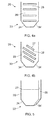
- the cross-sectional shape and/or cross-sectional area of the interspaced elongated ribs 28 may vary along the length of each rib. Examples of possible cross-sectional shapes (at 90 degrees to the direction of elongation/major axis (A-A) of the cast component) for the interspaced elongated ribs 28 are shown in Figures 3a-e .
- Figure 3a shows an elongated rib 28 with a semi-circular-shaped cross-section.
- Figure 3b shows an elongated rib 28 with a square-shaped cross-section.
- Figure 3c shows an elongated rib 28 with a triangular-shaped cross-section.
- Figure 3d shows an elongated rib 28 with a trapezoidal-shaped cross-section.
- Figure 3e shows an elongated rib 28 with a dovetail cross-section.
- the apices of the cross-sectional shapes shown in Figures 3b, 3c, 3d and 3e may optionally be rounded.
- FIGS 4a and 4b Alternative arrangements for the series of elongated recesses 27 inter-spaced by a series of elongated ribs 28 are shown in Figures 4a and 4b .
- the elongated recesses 27 and ribs 28 are aligned transverse to the major axis (A-A) of the cast component, i.e. at 90 degrees to the major axis.
- the elongated recesses 27 and ribs 28 are aligned at substantially 45 degrees to the major axis (A-A) of the cast component.
- the elongated recesses 27 are entirely contained within the anterior surface 29 of the tang portion 26.
- one or more of the elongated recesses 27 may extend into a side surface 31 of the tang portion 26, the side surface 31 separating the anterior and posterior surfaces 29, 30.
- Figures 6a-i show alternative arrangements for the series of recesses.
- the recesses are spaced circular recesses 27a, axially and transversely aligned with the major axis of the component.
- the recesses are elongated zig-zagged, axially aligned recesses 27b interspaced by elongated zig-zagged, axially aligned ribs 28b.
- the recesses are a series of rows of axially aligned, staggered rectangles 27c.
- the recesses are a series of axially aligned ovular recesses 27d.
- the recesses are a series of transversely aligned ovular recesses, 27e.
- the recesses are a series of transversely aligned dog-bone recesses, 27f.
- the recesses are spaced diamond-shaped recesses 27g, axially and transversely aligned with the major axis of the component.
- the recesses are elongated, axially aligned branched recesses 27h with the branch portions at least partly surrounding projections 32 on the anterior surface 29.
- the tip 33 of the anterior and posterior surfaces 29, 30 of the tang portion 26 is trapezoid-shaped.
- the angle of the two sloped edges 34, 34' is between 50 and 70 degrees to the vertical (where the vertical is at 90 degrees to the parallel edges).
- the tang portion is used to support the cast component during finishing and the tang portion is subsequently clipped from the cast component to form the turbine blade 24 for incorporation into the turbines 16, 17, 18 of the engine.
- the directional solidification process used for forming the cast component comprises forming a mould comprising a main body defining a cavity corresponding in shape to the blade body 25 and at least one mould portion defining a cavity with a reduced cross-sectional area corresponding in shape to the tang portion 26.
- the mould portion defining the tang cavity comprises the recess or series of recesses and ribs corresponding to those shown in Figures 2a-b , 3a-e , 4a-b, 5 and 6a-i since these recesses and ribs will define the recesses/ribs on the tang portion 26 of the cast component.
- the mould portion defining the tang cavity will be interposed between the main body of the mould and a selector portion, the selector portion defining a cavity corresponding to the shape of the pig-tail selector.
- molten metal will be poured into the mould and the mould slowly withdrawn (selector portion first) from a heating zone of a vacuum furnace into a cooling zone of the furnace towards an end chill plate.
- the mould portion defining the tang cavity enters the cooling zone, the increased surface area of the mould portion and the reduced thermal mass of the portion of the cast component within the mould portion results in increased radiative heat loss from the mould portion. This, in turn, results in a high thermal gradient across the solid/liquid metal interface which minimises defects in the single crystal structure of the component.
- the radiation of heat from the increased surface area is predominantly towards the walls of the cooling zone rather than the chill plate. This is because the increased surface area of the mould portion faces the walls of the cooling zone rather than the chill plate i.e. there is an increased view factor towards the walls of the cooling zone rather than towards the chill plate.
Landscapes
- Engineering & Computer Science (AREA)
- Mechanical Engineering (AREA)
- Physics & Mathematics (AREA)
- Fluid Mechanics (AREA)
- General Engineering & Computer Science (AREA)
- Turbine Rotor Nozzle Sealing (AREA)
Abstract
Description
- The present invention relates to component casting and, more particularly to component casting of directional solidification or single crystal components for engines such as a turbine blade having a portion with a reduced cross-sectional area e.g. a tang portion.
- The investment casting process is used to create metal components, e.g. turbine blades, by pouring molten metal into a ceramic shell of the desired final shape and subsequently removing the ceramic shell.
- The process is an evolution of the lost-wax process whereby a component of the size and shape required in metal is manufactured using a wax pattern die into which molten wax is injected. The wax pattern is then dipped in ceramic slurry to create a ceramic shell on the wax pattern. The wax is removed and the shell fired to harden it. The resulting ceramic shell has an open cavity of the size and shape of the final component into which the metal can be poured. The ceramic shell is subsequently removed, either physically or chemically.
- It is necessary to produce single crystal components for use in certain environments. For example, a turbine blade must be highly resistant to creep at high temperatures and so a single crystal with its absence of grain boundaries is the preferred structure.
- In order to achieve such a single crystal structure, a technique called directional solidification is used. This involves use of a spiral, "pig-tail" selector to initiate single crystal or grain growth followed by subsequent withdrawal of the mould (e.g. the ceramic shell) containing the cooling cast component from a heating zone into a cooling zone (having a chill plate) within a vacuum furnace at a predetermined rate such that the temperature gradient within the cast component is closely controlled. Generally, the "mushy zone" at the interface between the molten and solid metal in the cooling casting must be a calm (stagnant) interface with a flat temperature gradient in order to achieve a single crystal structure with no discontinuities. This is difficult to achieve in a component having a varying cross-sectional area along its profile because the heat radiated from the component will vary along its profile and convective instabilities will occur in the molten metal. As a result, an unacceptable proportion of cast components are rejected as a result of defects (e.g. freckling or secondary grains) formed during casting.
- It is known from
EP1452251-A1 to provide a horizontally oriented, displaced radiation deflector element in a mould for component casting. The radiation deflector element acts to reduce heat transfer between downward facing surfaces of the cast component (above the portions having a reduced cross sectional area) and the chill plate in the cooling zone of the furnace during directional solidification by acting as a barrier between the heating and cooling zones and reflecting heat back into the downward facing surfaces in the heating zone. This helps control (increase) the temperature gradient across the "mushy zone" which, in turn, helps reduce defects in the single crystal component by reducing buoyancy-induced defects such as freckling, sliver grains or high angle grain boundaries. - It is a preferred aim of the present invention to further control (increase) the temperature gradient at the liquid/solid metal interface ("mushy zone") upon cooling of cast component having a portion with a reduced cross-sectional area e.g. a tang portion of a turbine blade.
- In a first aspect, the present invention provides a mould for component casting using a directional solidification process, said mould comprising at least one mould portion defining a cavity with a reduced cross-sectional area which defines the shape of an element to be removed from the component in a subsequent manufacturing step, wherein said at least one mould portion comprises at least one recess which further reduces the cross-sectional area of the cavity and increases the surface area of the at least one mould portion or wherein said at least one mould portion comprises a plurality of projections which increase the surface area of the least one mould portion, such that, in use, the radiative heat loss from said at least one mould portion during said process is increased.
- In a second aspect, the mould of the first aspect can be used in a method of component casting using a directional solidification process comprising forming a mould, the mould having at least one mould portion defining a cavity with a reduced cross-sectional area which defines the shape of an element to be removed from the component in a subsequent manufacturing step, wherein said at least one mould portion comprises at least one recess which further reduces the cross-sectional area of the cavity and increases the surface area of the at least one mould portion or wherein said at least one mould portion comprises a plurality of projections which increase the surface area of the least one mould portion thereby increasing radiative heat loss from said at least one mould portion during said process.
- By providing the mould portion with a recess, the thermal mass of the portion of the cast component contained with the mould portion is reduced and the surface area of the mould portion is increased such that, during cooling of the cast component in the directional solidification process, the amount and rate of radiative heat loss from the mould portion in the cooling zone is increased. Similarly, by providing a portion of the mould with a plurality of projections, the surface area of the mould portion is increased such that, during cooling of the cast component in the directional solidification process, the amount and rate of radiative heat loss from the mould portion in the cooling zone is increased. This helps control (increase) the thermal gradient across the liquid/solid interface thus limiting defects in the single crystal structure of the component.
- In some embodiments, the element defined by the at least one mould portion may be a tang which serves not only to provide improved control of the temperature gradient, but can be used to support the component in post casting machining or surface finishing operations. The tang can be removed from the component as a subsequent post casting step in the manufacture of the finished component.
- Other optional features of the invention will now be set out. These are applicable singly or in any combination with any aspect of the invention.
- In some embodiments, there is a plurality of recesses in the at least one mould portion.
- In some embodiments, the or each recess is an elongated recess (or slot). Where there is a plurality of recesses, the recesses may be a series of elongated recesses (or slots) separated by one or more interspaced elongated ribs on the mould portion.
- The plurality of projections may be a series of elongated projections, e.g. elongated projecting ribs on the mould portion.
- The interspaced elongated rib(s) or plurality of projections/elongated projecting ribs may have a semi-circular-, square- (optionally with rounded vertices), triangular-, trapezoidal-, or dovetail-shaped cross section (at 90 degrees to the direction of elongation). The cross-section shape and/or cross-sectional area may vary along the length of the or each rib.
- The interspaced elongated rib(s) or plurality of projections/elongated projecting ribs may each have a through channel or bore to further increase the surface area of the mould portion.
- The recess, recesses and interspaced rib(s) or at least one of said plurality of projections/elongated projecting ribs may be zig-zagged.
- The or each recess may be branched with the branches at least partly surrounding a protrusion on the mould portion.
- At least one of the plurality of projections/elongated projecting ribs may be branched.
- In some embodiments, the elongated recess(es) or slot(s) or the plurality of projections/elongated projecting ribs is/are vertically aligned on the mould portion i.e. aligned with or parallel to the major axis of the mould. This major axis will be aligned with the vertical direction of withdrawal of the mould from the heating zone and aligned with the axis of the pig-tail selector.
- In these embodiments, the radiation of heat from the increased surface area is predominantly towards the walls of the cooling zone rather than the chill plate (which is typically provided at the end face of the cooling zone (towards which the mould is withdrawn during the directional solidification process)). This is because the increased surface area of the mould portion faces the walls of the cooling zone rather than the chill plate i.e. there is an increased view factor towards the walls of the cooling zone rather than (downwards) towards the chill plate.
- In other embodiments, the elongated recess(es) or slot(s) or the plurality of projections/elongated projecting ribs are aligned at an angle to the major axis of the mould. For example, they may be transversely aligned on the mould portion (i.e. at 90 degrees to the major axis of the mould) or they may be angled at angle less than 90 degrees, e.g. 45 degrees on the mould portion.
- In some embodiments, the or each recess or at least one of the plurality of projections may be a shaped recess/projection e.g. circular-, ovular-, diamond- or dog-bone-shaped recess/projection. A series of these shaped recesses may be provided and the series of recesses or the plurality of projections may be parallel to and/or transversely aligned with the major axis of the mould portion.
- The mould portion may have a posterior and anterior surface and the recess or series of recesses or plurality of projections/elongated projecting ribs as described above may be provided on one or both of said surfaces.
- The posterior and anterior surfaces may be separated by at least one side surface. The or each recess or each of said plurality of projections/elongated projecting ribs on the anterior and/or posterior surface may terminate before the side surface i.e. the recess or each recess/projection/projecting rib may be entirely contained within the respective surface. Alternatively, the recess or each recess/projection/projecting rib may extend into said at least one side surface.
- The mould may be for casting of a turbine blade and the mould may comprise a main body defining a cavity for forming a blade body. The mould portion defining the cavity with a reduced cross-sectional area may be for forming a tang portion of the turbine blade.
- Accordingly, in a third aspect, the present invention provides a method for casting a turbine blade using a directional solidification process comprising forming a mould, the mould having a main body defining a cavity corresponding in shape to a blade body and at least one mould portion defining a cavity with a reduced cross-sectional area corresponding in shape to a tang portion, wherein said at least one mould portion comprises at least one recess which further reduces the cross sectional area of the tang portion cavity and increases the surface area of the at least one mould portion or wherein said at least one mould portion comprises a plurality of projections which increase the surface area of the least one mould portion thereby increasing radiative heat loss from said at least one mould portion during said process.
- In a fourth aspect, the present invention provides a mould for casting a turbine blade using a directional solidification process, said mould comprising a main body defining a cavity corresponding in shape to a blade body and at least one mould portion defining a cavity with a reduced cross-sectional area corresponding in shape to a tang portion, wherein said at least one mould portion comprises at least one recess which further reduces the cross sectional area of the tang portion cavity and increases the surface area of the at least one mould portion or wherein said at least one mould portion comprises a plurality of projections which increase the surface area of the least one mould portion, such that, in use, the radiative heat loss from said at least one mould portion during said process is increased.
- For the third and fourth aspects, the mould portion comprising at least one recess or a plurality of projections is as described with reference to the first and second aspects.
- In some embodiments, the mould comprises two axially opposed mould portions defining cavities of reduced cross-sectional area corresponding in shape to the axially opposed tang portions.
- One mould portion defining the tang portion cavity will be located between the main body and a selector portion, the selector portion defining a cavity corresponding to the shape of the pig-tail selector.
- The anterior and posterior surfaces of the mould portion(s) defining the tang cavity/cavities may each have a tip which is trapezoid shaped (with the longest of the two parallel edges located proximal the main body of the mould). The angle of the two sloped edges may be between 50 and 70 degrees (preferably around 60 degrees) to the vertical (where the vertical is at 90 degrees to the parallel edges).
- In a fifth aspect, the present invention provides a turbine blade formed according to the method of the first aspect and using a mould according to the second aspect.
- After forming the turbine blade, the tang portion(s) are clipped from the blade body.
- In a sixth aspect, the present invention provides a turbine blade having a blade body and at least one tang portion having an anterior and posterior surface where at least one of said surfaces comprises at least one recess or wherein said at least one of said surfaces comprises a plurality of projections.
- The recessed tang has been found to retain its rigidity allowing its continued use for supporting the cast blade body during processing but with reduced metal content thus saving raw material costs during manufacturing.
- In some embodiments, the turbine blade has two axially opposed recessed tang portions.
- The anterior and/or posterior surface(s) of the tang portion(s) will include the recess(es)/plurality of projections/elongated projecting ribs described above for the mould portion of the first and second aspects (since the anterior/posterior surfaces of the mould portion(s) will define the anterior/posterior surfaces of the tang portions).
- The tips of the anterior and posterior surfaces of the tang portion(s) may be trapezoid shaped (with the longest of the two parallel edges located proximal the blade body). The angle of the two sloped edges may be between 50 and 70 degrees to the vertical (where the vertical is at 90 degrees to the parallel edges).
- In a seventh aspect, the present invention provides a turbine for a gas turbine engine, the turbine comprising a plurality of turbine blades according to the fifth or sixth aspect.
- In an eighth aspect, the present invention provides a gas turbine engine having a turbine according to the seventh aspect.
- Embodiments of the invention will now be described by way of example with reference to the accompanying drawings in which:
-
Figure 1 shows a ducted fan gas turbine engine incorporating a series of turbines each having a plurality of aerofoil blades formed using a method according to an embodiment of the present invention. -
Figure 2a shows a tang portion of a turbine blade cast using a method according to an embodiment of the present invention. -
Figure 2b shows a cross-sectional view of the tang portion ofFigure 2a . -
Figures 3a-e show possible cross-sectional shapes for the elongated ribs shown inFigures 2a and 2b . -
Figures 4a and 4b show second and third embodiments of a tang portion with alternative arrangements for the series of elongated recesses. -
Figure 5 shows a fourth embodiment of a tang portion with a recess extending into a side surface. -
Figures 6a-6i show further embodiments of a tang portion with shaped recesses. - With reference to
Figure 1 , a ducted fan gas turbine engine incorporating a series of turbines each having a plurality of aerofoil blades formed using a method according to an embodiment of the present invention is generally indicated at 10 and has a principal and rotational axis X-X. The engine comprises, in axial flow series, anair intake 11, thepropulsive fan 12, anintermediate pressure compressor 13, a high-pressure compressor 14,combustion equipment 15, a high-pressure turbine 16, anintermediate pressure turbine 17, a low-pressure turbine 18 and a coreengine exhaust nozzle 19. A nacelle 21 generally surrounds theengine 10 and defines theintake 11, abypass duct 22 and abypass exhaust nozzle 23. - During operation, air entering the
intake 11 is accelerated by thefan 12 to produce two air flows: a first air flow A into theintermediate pressure compressor 13 and a second air flow B which passes through thebypass duct 22 to provide propulsive thrust. Theintermediate pressure compressor 13 compresses the air flow A directed into it before delivering that air to thehigh pressure compressor 14 where further compression takes place. - The compressed air exhausted from the high-
pressure compressor 14 is directed into thecombustion equipment 15 where it is mixed with fuel and the mixture combusted. The resultant hot combustion products then expand through, and thereby drive the high, intermediate and low-pressure turbines nozzle 19 to provide additional propulsive thrust. The high, intermediate and low-pressure turbines respectively drive the high andintermediate pressure compressors fan 12 by suitable interconnecting shafts. - The
turbines - Each turbine blade is cast from molten metal (e.g. a nickel-based super-alloy) using a directional solidification process. As seen in
Figures 2a and 2b , the resulting cast component has ablade body 25 and two opposing tang portions 26 (only one shown). - The
anterior surface 29 of thetang portion 26 comprises a series ofelongated recesses 27 inter-spaced by a series ofelongated ribs 28. The elongated recesses 27 andribs 28 are axially aligned with the major axis (A-A) of the cast component. Theposterior surface 30 of thetang portion 26 also comprises a series of elongated recesses 27' and ribs 28'. - The cross-sectional shape and/or cross-sectional area of the interspaced
elongated ribs 28 may vary along the length of each rib. Examples of possible cross-sectional shapes (at 90 degrees to the direction of elongation/major axis (A-A) of the cast component) for the interspacedelongated ribs 28 are shown inFigures 3a-e . -
Figure 3a , shows anelongated rib 28 with a semi-circular-shaped cross-section.Figure 3b , shows anelongated rib 28 with a square-shaped cross-section.Figure 3c , shows anelongated rib 28 with a triangular-shaped cross-section.Figure 3d , shows anelongated rib 28 with a trapezoidal-shaped cross-section.Figure 3e , shows anelongated rib 28 with a dovetail cross-section. The apices of the cross-sectional shapes shown inFigures 3b, 3c, 3d and 3e may optionally be rounded. - Alternative arrangements for the series of
elongated recesses 27 inter-spaced by a series ofelongated ribs 28 are shown inFigures 4a and 4b . InFigure 4a , theelongated recesses 27 andribs 28 are aligned transverse to the major axis (A-A) of the cast component, i.e. at 90 degrees to the major axis. Infigure 4b , theelongated recesses 27 andribs 28 are aligned at substantially 45 degrees to the major axis (A-A) of the cast component. - In the embodiments, shown in
Figures 4a and 4b , theelongated recesses 27 are entirely contained within theanterior surface 29 of thetang portion 26. - As shown in
Figure 5 , one or more of theelongated recesses 27 may extend into a side surface 31 of thetang portion 26, the side surface 31 separating the anterior andposterior surfaces -
Figures 6a-i show alternative arrangements for the series of recesses. InFigure 6a , the recesses are spacedcircular recesses 27a, axially and transversely aligned with the major axis of the component. InFigure 6b , the recesses are elongated zig-zagged, axially alignedrecesses 27b interspaced by elongated zig-zagged, axially alignedribs 28b. InFigure 6c , the recesses are a series of rows of axially aligned, staggered rectangles 27c. InFigure 6d , the recesses are a series of axially alignedovular recesses 27d. InFigure 6e , the recesses are a series of transversely aligned ovular recesses, 27e. InFigure 6f , the recesses are a series of transversely aligned dog-bone recesses, 27f. InFigure 6g , the recesses are spaced diamond-shapedrecesses 27g, axially and transversely aligned with the major axis of the component. InFigures 6h and 6i , the recesses are elongated, axially aligned branchedrecesses 27h with the branch portions at least partly surroundingprojections 32 on theanterior surface 29. - The
tip 33 of the anterior andposterior surfaces tang portion 26 is trapezoid-shaped. The angle of the two slopededges 34, 34' is between 50 and 70 degrees to the vertical (where the vertical is at 90 degrees to the parallel edges). - The tang portion is used to support the cast component during finishing and the tang portion is subsequently clipped from the cast component to form the turbine blade 24 for incorporation into the
turbines - The directional solidification process used for forming the cast component comprises forming a mould comprising a main body defining a cavity corresponding in shape to the
blade body 25 and at least one mould portion defining a cavity with a reduced cross-sectional area corresponding in shape to thetang portion 26. - The mould portion defining the tang cavity comprises the recess or series of recesses and ribs corresponding to those shown in
Figures 2a-b ,3a-e ,4a-b, 5 and6a-i since these recesses and ribs will define the recesses/ribs on thetang portion 26 of the cast component. - The mould portion defining the tang cavity will be interposed between the main body of the mould and a selector portion, the selector portion defining a cavity corresponding to the shape of the pig-tail selector.
- During the directional solidification process, molten metal will be poured into the mould and the mould slowly withdrawn (selector portion first) from a heating zone of a vacuum furnace into a cooling zone of the furnace towards an end chill plate. As the mould portion defining the tang cavity enters the cooling zone, the increased surface area of the mould portion and the reduced thermal mass of the portion of the cast component within the mould portion results in increased radiative heat loss from the mould portion. This, in turn, results in a high thermal gradient across the solid/liquid metal interface which minimises defects in the single crystal structure of the component.
- In the embodiments shown in
figures 2a-b ,6b-d and 6g-i , the radiation of heat from the increased surface area is predominantly towards the walls of the cooling zone rather than the chill plate. This is because the increased surface area of the mould portion faces the walls of the cooling zone rather than the chill plate i.e. there is an increased view factor towards the walls of the cooling zone rather than towards the chill plate. - While the invention has been described in conjunction with the exemplary embodiments described above, many equivalent modifications and variations will be apparent to those skilled in the art when given this disclosure. Accordingly, the exemplary embodiments of the invention set forth above are considered to be illustrative and not limiting. Various changes to the described embodiments may be made without departing from the spirit and scope of the invention.
Claims (16)
- A mould for component (25) casting using a directional solidification process, said mould comprising at least one mould portion which defines the shape of an element (26) to be removed from the component (25) in a subsequent manufacturing step, the at least one mould portion defining a cavity with a reduced cross-sectional area, wherein said at least one mould portion comprises at least one recess which further reduces the cross sectional area of the cavity and increases the surface area of the at least one mould portion or a plurality of projections which increase the surface area of the least one mould portion, such that, in use, the radiative heat loss from said at least one mould portion during said directional solidification process is increased.
- A mould according to claim 1 wherein at least one mould portion comprises a plurality of recesses.
- A mould according to claim 1 or 2 wherein the at least one mould portion comprises a plurality of projections and the projections are elongated projecting ribs.
- A mould according to claim 3 wherein the plurality of recesses are elongated recesses and are separated by one or more interspaced elongated projecting ribs.
- A mould according to any preceding claim wherein the plurality of projections have a semi-circular-, square-, triangular-, trapezoidal-, or dovetail-shaped cross section (at 90 degrees to a direction of elongation of the projection).
- A mould according to any preceding claim wherein the recesses and/or projections, have a major axis and this axis is arranged parallel to the major axis of the mould portion.
- A mould according to any one of claims 1 to 5 wherein the recesses and/or projections, have a major axis and this axis is transversely aligned with the major axis of the mould portion.
- A mould according to any one of claims 1 to 7 wherein the recesses and/or projections are arranged in zig-zag pattern.
- A mould according to any one of claims 1 to 8 wherein the recesses and/or projections are branched.
- A mould according to claim 1, 2 or 3 wherein the or each recess or at least one of said plurality of projections is circular-, ovular-, diamond- or dog-bone-shaped.
- A mould according to any preceding claim wherein the mould portion has a posterior and anterior surface and the recess or series of recesses or plurality of projections/elongated projecting ribs is provided on one or both of said surfaces.
- A mould according to any preceding claim for casting a turbine blade wherein the mould comprises a main body defining a cavity for forming a blade body and the mould portion defining the cavity with a reduced cross-sectional area is for forming a tang portion of the turbine blade to be removed during subsequent manufacturing steps.
- A turbine blade (25) formed using a mould according to any one of claims 1 to 12.
- A gas turbine engine (10) having a turbine blade (25) according to claim 13.
- A turbine blade (25) according to claim 13 wherein the tang portion (26) has anterior (29) and posterior surfaces which are trapezoid shaped with the longest of the two parallel edges of the trapezoid located proximal the blade body and the angle of the two sloped edges is between 50 and 70 degrees to the vertical.
- A method for manufacturing a turbine blade comprising;
providing a mould said mould comprising a main body defining a main cavity for casting a blade body and at least one additional mould portion which defines the shape of a tang of reduced cross sectional area compared to the main body to be removed from the cast blade body in a subsequent manufacturing step, the at least one mould portion defining a cavity comprising at least one recess which further reduces the cross sectional area of the cavity and increases the surface area of the at least one mould portion or a plurality of projections which increase the surface area of the least one mould portion, such that, in use, the radiative heat loss from said at least one mould portion during said directional solidification process is increased;
casting the blade body and tang using a directional solidification process;
using the at least one tang to support the cast blade, machining additional features of the turbine blade into the cast blade body;
removing the at least one tang.
Applications Claiming Priority (1)
| Application Number | Priority Date | Filing Date | Title |
|---|---|---|---|
| GBGB1411680.0A GB201411680D0 (en) | 2014-07-01 | 2014-07-01 | Component casting |
Publications (2)
| Publication Number | Publication Date |
|---|---|
| EP2987570A1 true EP2987570A1 (en) | 2016-02-24 |
| EP2987570B1 EP2987570B1 (en) | 2019-08-07 |
Family
ID=51410422
Family Applications (1)
| Application Number | Title | Priority Date | Filing Date |
|---|---|---|---|
| EP15170445.9A Active EP2987570B1 (en) | 2014-07-01 | 2015-06-03 | Component casting |
Country Status (3)
| Country | Link |
|---|---|
| US (1) | US10399143B2 (en) |
| EP (1) | EP2987570B1 (en) |
| GB (1) | GB201411680D0 (en) |
Citations (3)
| Publication number | Priority date | Publication date | Assignee | Title |
|---|---|---|---|---|
| EP1452251A1 (en) * | 2003-02-26 | 2004-09-01 | ROLLS-ROYCE plc | Method and mould for component casting using a directional solidification process |
| FR2874340A1 (en) * | 2004-08-20 | 2006-02-24 | Snecma Moteurs Sa | Foundry method for fabricating jet engine blade, involves manufacturing shell whose additional part is arranged on another part, where additional part is plane and perpendicular to vertical axis of latter part |
| GB2432133A (en) * | 2005-11-15 | 2007-05-16 | Rolls Royce Plc | A feeder for a cast turbine blade |
Family Cites Families (7)
| Publication number | Priority date | Publication date | Assignee | Title |
|---|---|---|---|---|
| JPH1034280A (en) | 1996-05-24 | 1998-02-10 | Mitsubishi Heavy Ind Ltd | Mold for precision molding of single crystal |
| JPH10156484A (en) | 1996-11-20 | 1998-06-16 | Mitsubishi Heavy Ind Ltd | Mold for precision casting |
| JP2003529677A (en) | 1999-07-29 | 2003-10-07 | シーメンス アクチエンゲゼルシヤフト | Heat resistant structural member and method of manufacturing the same |
| JP2002178133A (en) | 2000-12-19 | 2002-06-25 | Suzuki Motor Corp | Aluminum or aluminum alloy casting method, and mold used in this casting method |
| JP3794993B2 (en) | 2002-07-29 | 2006-07-12 | 三菱重工業株式会社 | Unidirectional solidified blade molding mold, one-directional solidified blade manufacturing method using the mold, and one-directional solidified blade |
| JP2005238744A (en) * | 2004-02-27 | 2005-09-08 | Bridgestone Corp | Blade implantation method, tire vulcanization mold and blade |
| DE102007054520B4 (en) * | 2007-11-06 | 2013-01-17 | Electronics Gmbh Vertrieb Elektronischer Geräte | Venting device for a die casting device |
-
2014
- 2014-07-01 GB GBGB1411680.0A patent/GB201411680D0/en not_active Ceased
-
2015
- 2015-06-03 EP EP15170445.9A patent/EP2987570B1/en active Active
- 2015-06-03 US US14/729,912 patent/US10399143B2/en active Active
Patent Citations (3)
| Publication number | Priority date | Publication date | Assignee | Title |
|---|---|---|---|---|
| EP1452251A1 (en) * | 2003-02-26 | 2004-09-01 | ROLLS-ROYCE plc | Method and mould for component casting using a directional solidification process |
| FR2874340A1 (en) * | 2004-08-20 | 2006-02-24 | Snecma Moteurs Sa | Foundry method for fabricating jet engine blade, involves manufacturing shell whose additional part is arranged on another part, where additional part is plane and perpendicular to vertical axis of latter part |
| GB2432133A (en) * | 2005-11-15 | 2007-05-16 | Rolls Royce Plc | A feeder for a cast turbine blade |
Also Published As
| Publication number | Publication date |
|---|---|
| EP2987570B1 (en) | 2019-08-07 |
| US10399143B2 (en) | 2019-09-03 |
| US20160001360A1 (en) | 2016-01-07 |
| GB201411680D0 (en) | 2014-08-13 |
Similar Documents
| Publication | Publication Date | Title |
|---|---|---|
| US7780414B1 (en) | Turbine blade with multiple metering trailing edge cooling holes | |
| US7938624B2 (en) | Cooling arrangement for a component of a gas turbine engine | |
| US7674093B2 (en) | Cluster bridged casting core | |
| JP4416417B2 (en) | Method and apparatus for cooling a gas turbine nozzle | |
| US6340047B1 (en) | Core tied cast airfoil | |
| US9938837B2 (en) | Gas turbine engine airfoil trailing edge passage and core for making same | |
| EP3181263B1 (en) | Method and assembly for forming components having internal passages using a lattice structure | |
| JP2006300056A (en) | Airfoil and its forming method | |
| US8784044B2 (en) | Turbine shroud segment | |
| US6599092B1 (en) | Methods and apparatus for cooling gas turbine nozzles | |
| CN107849930B (en) | High pressure distributor vane arrangement with variable geometry insert | |
| US8303252B2 (en) | Airfoil with cooling passage providing variable heat transfer rate | |
| RU2687949C2 (en) | Method of making two-component blade for gas turbine engine and blade, obtainable by such method | |
| EP2959988A2 (en) | Core positioning | |
| JP7091019B2 (en) | Methods and assemblies for forming components with internal passages defined inside | |
| US12595742B2 (en) | Turbine component with a thin interior partition | |
| EP1801350A2 (en) | Apparatus for cooling turbine engine blade trailing edges | |
| EP2987570B1 (en) | Component casting | |
| CN107030260B (en) | Method and assembly for forming a member with internal passages using a sheathed core | |
| EP3181265A1 (en) | Method and assembly for forming components having internal passages using a lattice structure | |
| US10954799B2 (en) | Gas turbine engine blade with variable density and wide chord tip | |
| KR101875692B1 (en) | A gas turbine blade comprising an inner flow path structure in the form of a fabric for cooling a gas turbine |
Legal Events
| Date | Code | Title | Description |
|---|---|---|---|
| PUAI | Public reference made under article 153(3) epc to a published international application that has entered the european phase |
Free format text: ORIGINAL CODE: 0009012 |
|
| AK | Designated contracting states |
Kind code of ref document: A1 Designated state(s): AL AT BE BG CH CY CZ DE DK EE ES FI FR GB GR HR HU IE IS IT LI LT LU LV MC MK MT NL NO PL PT RO RS SE SI SK SM TR |
|
| AX | Request for extension of the european patent |
Extension state: BA ME |
|
| 17P | Request for examination filed |
Effective date: 20160302 |
|
| RBV | Designated contracting states (corrected) |
Designated state(s): AL AT BE BG CH CY CZ DE DK EE ES FI FR GB GR HR HU IE IS IT LI LT LU LV MC MK MT NL NO PL PT RO RS SE SI SK SM TR |
|
| STAA | Information on the status of an ep patent application or granted ep patent |
Free format text: STATUS: EXAMINATION IS IN PROGRESS |
|
| 17Q | First examination report despatched |
Effective date: 20180223 |
|
| GRAP | Despatch of communication of intention to grant a patent |
Free format text: ORIGINAL CODE: EPIDOSNIGR1 |
|
| STAA | Information on the status of an ep patent application or granted ep patent |
Free format text: STATUS: GRANT OF PATENT IS INTENDED |
|
| GRAS | Grant fee paid |
Free format text: ORIGINAL CODE: EPIDOSNIGR3 |
|
| INTG | Intention to grant announced |
Effective date: 20190417 |
|
| GRAA | (expected) grant |
Free format text: ORIGINAL CODE: 0009210 |
|
| STAA | Information on the status of an ep patent application or granted ep patent |
Free format text: STATUS: THE PATENT HAS BEEN GRANTED |
|
| AK | Designated contracting states |
Kind code of ref document: B1 Designated state(s): AL AT BE BG CH CY CZ DE DK EE ES FI FR GB GR HR HU IE IS IT LI LT LU LV MC MK MT NL NO PL PT RO RS SE SI SK SM TR |
|
| REG | Reference to a national code |
Ref country code: GB Ref legal event code: FG4D |
|
| REG | Reference to a national code |
Ref country code: CH Ref legal event code: EP Ref country code: AT Ref legal event code: REF Ref document number: 1163066 Country of ref document: AT Kind code of ref document: T Effective date: 20190815 |
|
| REG | Reference to a national code |
Ref country code: IE Ref legal event code: FG4D |
|
| REG | Reference to a national code |
Ref country code: DE Ref legal event code: R096 Ref document number: 602015035104 Country of ref document: DE |
|
| REG | Reference to a national code |
Ref country code: NL Ref legal event code: MP Effective date: 20190807 |
|
| REG | Reference to a national code |
Ref country code: LT Ref legal event code: MG4D |
|
| PG25 | Lapsed in a contracting state [announced via postgrant information from national office to epo] |
Ref country code: HR Free format text: LAPSE BECAUSE OF FAILURE TO SUBMIT A TRANSLATION OF THE DESCRIPTION OR TO PAY THE FEE WITHIN THE PRESCRIBED TIME-LIMIT Effective date: 20190807 Ref country code: NL Free format text: LAPSE BECAUSE OF FAILURE TO SUBMIT A TRANSLATION OF THE DESCRIPTION OR TO PAY THE FEE WITHIN THE PRESCRIBED TIME-LIMIT Effective date: 20190807 Ref country code: BG Free format text: LAPSE BECAUSE OF FAILURE TO SUBMIT A TRANSLATION OF THE DESCRIPTION OR TO PAY THE FEE WITHIN THE PRESCRIBED TIME-LIMIT Effective date: 20191107 Ref country code: SE Free format text: LAPSE BECAUSE OF FAILURE TO SUBMIT A TRANSLATION OF THE DESCRIPTION OR TO PAY THE FEE WITHIN THE PRESCRIBED TIME-LIMIT Effective date: 20190807 Ref country code: PT Free format text: LAPSE BECAUSE OF FAILURE TO SUBMIT A TRANSLATION OF THE DESCRIPTION OR TO PAY THE FEE WITHIN THE PRESCRIBED TIME-LIMIT Effective date: 20191209 Ref country code: LT Free format text: LAPSE BECAUSE OF FAILURE TO SUBMIT A TRANSLATION OF THE DESCRIPTION OR TO PAY THE FEE WITHIN THE PRESCRIBED TIME-LIMIT Effective date: 20190807 Ref country code: FI Free format text: LAPSE BECAUSE OF FAILURE TO SUBMIT A TRANSLATION OF THE DESCRIPTION OR TO PAY THE FEE WITHIN THE PRESCRIBED TIME-LIMIT Effective date: 20190807 Ref country code: NO Free format text: LAPSE BECAUSE OF FAILURE TO SUBMIT A TRANSLATION OF THE DESCRIPTION OR TO PAY THE FEE WITHIN THE PRESCRIBED TIME-LIMIT Effective date: 20191107 |
|
| REG | Reference to a national code |
Ref country code: AT Ref legal event code: MK05 Ref document number: 1163066 Country of ref document: AT Kind code of ref document: T Effective date: 20190807 |
|
| RAP2 | Party data changed (patent owner data changed or rights of a patent transferred) |
Owner name: ROLLS-ROYCE PLC |
|
| PG25 | Lapsed in a contracting state [announced via postgrant information from national office to epo] |
Ref country code: IS Free format text: LAPSE BECAUSE OF FAILURE TO SUBMIT A TRANSLATION OF THE DESCRIPTION OR TO PAY THE FEE WITHIN THE PRESCRIBED TIME-LIMIT Effective date: 20191207 Ref country code: GR Free format text: LAPSE BECAUSE OF FAILURE TO SUBMIT A TRANSLATION OF THE DESCRIPTION OR TO PAY THE FEE WITHIN THE PRESCRIBED TIME-LIMIT Effective date: 20191108 Ref country code: RS Free format text: LAPSE BECAUSE OF FAILURE TO SUBMIT A TRANSLATION OF THE DESCRIPTION OR TO PAY THE FEE WITHIN THE PRESCRIBED TIME-LIMIT Effective date: 20190807 Ref country code: ES Free format text: LAPSE BECAUSE OF FAILURE TO SUBMIT A TRANSLATION OF THE DESCRIPTION OR TO PAY THE FEE WITHIN THE PRESCRIBED TIME-LIMIT Effective date: 20190807 Ref country code: AL Free format text: LAPSE BECAUSE OF FAILURE TO SUBMIT A TRANSLATION OF THE DESCRIPTION OR TO PAY THE FEE WITHIN THE PRESCRIBED TIME-LIMIT Effective date: 20190807 Ref country code: LV Free format text: LAPSE BECAUSE OF FAILURE TO SUBMIT A TRANSLATION OF THE DESCRIPTION OR TO PAY THE FEE WITHIN THE PRESCRIBED TIME-LIMIT Effective date: 20190807 |
|
| PG25 | Lapsed in a contracting state [announced via postgrant information from national office to epo] |
Ref country code: TR Free format text: LAPSE BECAUSE OF FAILURE TO SUBMIT A TRANSLATION OF THE DESCRIPTION OR TO PAY THE FEE WITHIN THE PRESCRIBED TIME-LIMIT Effective date: 20190807 |
|
| PG25 | Lapsed in a contracting state [announced via postgrant information from national office to epo] |
Ref country code: DK Free format text: LAPSE BECAUSE OF FAILURE TO SUBMIT A TRANSLATION OF THE DESCRIPTION OR TO PAY THE FEE WITHIN THE PRESCRIBED TIME-LIMIT Effective date: 20190807 Ref country code: EE Free format text: LAPSE BECAUSE OF FAILURE TO SUBMIT A TRANSLATION OF THE DESCRIPTION OR TO PAY THE FEE WITHIN THE PRESCRIBED TIME-LIMIT Effective date: 20190807 Ref country code: AT Free format text: LAPSE BECAUSE OF FAILURE TO SUBMIT A TRANSLATION OF THE DESCRIPTION OR TO PAY THE FEE WITHIN THE PRESCRIBED TIME-LIMIT Effective date: 20190807 Ref country code: RO Free format text: LAPSE BECAUSE OF FAILURE TO SUBMIT A TRANSLATION OF THE DESCRIPTION OR TO PAY THE FEE WITHIN THE PRESCRIBED TIME-LIMIT Effective date: 20190807 Ref country code: IT Free format text: LAPSE BECAUSE OF FAILURE TO SUBMIT A TRANSLATION OF THE DESCRIPTION OR TO PAY THE FEE WITHIN THE PRESCRIBED TIME-LIMIT Effective date: 20190807 Ref country code: PL Free format text: LAPSE BECAUSE OF FAILURE TO SUBMIT A TRANSLATION OF THE DESCRIPTION OR TO PAY THE FEE WITHIN THE PRESCRIBED TIME-LIMIT Effective date: 20190807 |
|
| PG25 | Lapsed in a contracting state [announced via postgrant information from national office to epo] |
Ref country code: SM Free format text: LAPSE BECAUSE OF FAILURE TO SUBMIT A TRANSLATION OF THE DESCRIPTION OR TO PAY THE FEE WITHIN THE PRESCRIBED TIME-LIMIT Effective date: 20190807 Ref country code: SK Free format text: LAPSE BECAUSE OF FAILURE TO SUBMIT A TRANSLATION OF THE DESCRIPTION OR TO PAY THE FEE WITHIN THE PRESCRIBED TIME-LIMIT Effective date: 20190807 Ref country code: CZ Free format text: LAPSE BECAUSE OF FAILURE TO SUBMIT A TRANSLATION OF THE DESCRIPTION OR TO PAY THE FEE WITHIN THE PRESCRIBED TIME-LIMIT Effective date: 20190807 Ref country code: IS Free format text: LAPSE BECAUSE OF FAILURE TO SUBMIT A TRANSLATION OF THE DESCRIPTION OR TO PAY THE FEE WITHIN THE PRESCRIBED TIME-LIMIT Effective date: 20200224 |
|
| REG | Reference to a national code |
Ref country code: DE Ref legal event code: R097 Ref document number: 602015035104 Country of ref document: DE |
|
| PLBE | No opposition filed within time limit |
Free format text: ORIGINAL CODE: 0009261 |
|
| STAA | Information on the status of an ep patent application or granted ep patent |
Free format text: STATUS: NO OPPOSITION FILED WITHIN TIME LIMIT |
|
| PG2D | Information on lapse in contracting state deleted |
Ref country code: IS |
|
| 26N | No opposition filed |
Effective date: 20200603 |
|
| PG25 | Lapsed in a contracting state [announced via postgrant information from national office to epo] |
Ref country code: SI Free format text: LAPSE BECAUSE OF FAILURE TO SUBMIT A TRANSLATION OF THE DESCRIPTION OR TO PAY THE FEE WITHIN THE PRESCRIBED TIME-LIMIT Effective date: 20190807 |
|
| PG25 | Lapsed in a contracting state [announced via postgrant information from national office to epo] |
Ref country code: MC Free format text: LAPSE BECAUSE OF FAILURE TO SUBMIT A TRANSLATION OF THE DESCRIPTION OR TO PAY THE FEE WITHIN THE PRESCRIBED TIME-LIMIT Effective date: 20190807 |
|
| REG | Reference to a national code |
Ref country code: CH Ref legal event code: PL |
|
| PG25 | Lapsed in a contracting state [announced via postgrant information from national office to epo] |
Ref country code: LU Free format text: LAPSE BECAUSE OF NON-PAYMENT OF DUE FEES Effective date: 20200603 |
|
| REG | Reference to a national code |
Ref country code: BE Ref legal event code: MM Effective date: 20200630 |
|
| PG25 | Lapsed in a contracting state [announced via postgrant information from national office to epo] |
Ref country code: CH Free format text: LAPSE BECAUSE OF NON-PAYMENT OF DUE FEES Effective date: 20200630 Ref country code: IE Free format text: LAPSE BECAUSE OF NON-PAYMENT OF DUE FEES Effective date: 20200603 Ref country code: LI Free format text: LAPSE BECAUSE OF NON-PAYMENT OF DUE FEES Effective date: 20200630 |
|
| PG25 | Lapsed in a contracting state [announced via postgrant information from national office to epo] |
Ref country code: BE Free format text: LAPSE BECAUSE OF NON-PAYMENT OF DUE FEES Effective date: 20200630 |
|
| PGFP | Annual fee paid to national office [announced via postgrant information from national office to epo] |
Ref country code: FR Payment date: 20210625 Year of fee payment: 7 |
|
| PGFP | Annual fee paid to national office [announced via postgrant information from national office to epo] |
Ref country code: GB Payment date: 20210625 Year of fee payment: 7 |
|
| PGFP | Annual fee paid to national office [announced via postgrant information from national office to epo] |
Ref country code: DE Payment date: 20210827 Year of fee payment: 7 |
|
| PG25 | Lapsed in a contracting state [announced via postgrant information from national office to epo] |
Ref country code: MT Free format text: LAPSE BECAUSE OF FAILURE TO SUBMIT A TRANSLATION OF THE DESCRIPTION OR TO PAY THE FEE WITHIN THE PRESCRIBED TIME-LIMIT Effective date: 20190807 Ref country code: CY Free format text: LAPSE BECAUSE OF FAILURE TO SUBMIT A TRANSLATION OF THE DESCRIPTION OR TO PAY THE FEE WITHIN THE PRESCRIBED TIME-LIMIT Effective date: 20190807 |
|
| PG25 | Lapsed in a contracting state [announced via postgrant information from national office to epo] |
Ref country code: MK Free format text: LAPSE BECAUSE OF FAILURE TO SUBMIT A TRANSLATION OF THE DESCRIPTION OR TO PAY THE FEE WITHIN THE PRESCRIBED TIME-LIMIT Effective date: 20190807 |
|
| REG | Reference to a national code |
Ref country code: DE Ref legal event code: R119 Ref document number: 602015035104 Country of ref document: DE |
|
| GBPC | Gb: european patent ceased through non-payment of renewal fee |
Effective date: 20220603 |
|
| PG25 | Lapsed in a contracting state [announced via postgrant information from national office to epo] |
Ref country code: FR Free format text: LAPSE BECAUSE OF NON-PAYMENT OF DUE FEES Effective date: 20220630 |
|
| PG25 | Lapsed in a contracting state [announced via postgrant information from national office to epo] |
Ref country code: GB Free format text: LAPSE BECAUSE OF NON-PAYMENT OF DUE FEES Effective date: 20220603 Ref country code: DE Free format text: LAPSE BECAUSE OF NON-PAYMENT OF DUE FEES Effective date: 20230103 |