EP2987563A1 - Vibration generation device - Google Patents
Vibration generation device Download PDFInfo
- Publication number
- EP2987563A1 EP2987563A1 EP14785447.5A EP14785447A EP2987563A1 EP 2987563 A1 EP2987563 A1 EP 2987563A1 EP 14785447 A EP14785447 A EP 14785447A EP 2987563 A1 EP2987563 A1 EP 2987563A1
- Authority
- EP
- European Patent Office
- Prior art keywords
- rotary
- rotary shaft
- rotary shafts
- rotary drive
- shafts
- Prior art date
- Legal status (The legal status is an assumption and is not a legal conclusion. Google has not performed a legal analysis and makes no representation as to the accuracy of the status listed.)
- Granted
Links
Images





Classifications
-
- H—ELECTRICITY
- H02—GENERATION; CONVERSION OR DISTRIBUTION OF ELECTRIC POWER
- H02K—DYNAMO-ELECTRIC MACHINES
- H02K7/00—Arrangements for handling mechanical energy structurally associated with dynamo-electric machines, e.g. structural association with mechanical driving motors or auxiliary dynamo-electric machines
- H02K7/06—Means for converting reciprocating motion into rotary motion or vice versa
- H02K7/061—Means for converting reciprocating motion into rotary motion or vice versa using rotary unbalanced masses
-
- B—PERFORMING OPERATIONS; TRANSPORTING
- B07—SEPARATING SOLIDS FROM SOLIDS; SORTING
- B07B—SEPARATING SOLIDS FROM SOLIDS BY SIEVING, SCREENING, SIFTING OR BY USING GAS CURRENTS; SEPARATING BY OTHER DRY METHODS APPLICABLE TO BULK MATERIAL, e.g. LOOSE ARTICLES FIT TO BE HANDLED LIKE BULK MATERIAL
- B07B1/00—Sieving, screening, sifting, or sorting solid materials using networks, gratings, grids, or the like
- B07B1/42—Drive mechanisms, regulating or controlling devices, or balancing devices, specially adapted for screens
-
- B—PERFORMING OPERATIONS; TRANSPORTING
- B06—GENERATING OR TRANSMITTING MECHANICAL VIBRATIONS IN GENERAL
- B06B—METHODS OR APPARATUS FOR GENERATING OR TRANSMITTING MECHANICAL VIBRATIONS OF INFRASONIC, SONIC, OR ULTRASONIC FREQUENCY, e.g. FOR PERFORMING MECHANICAL WORK IN GENERAL
- B06B1/00—Methods or apparatus for generating mechanical vibrations of infrasonic, sonic, or ultrasonic frequency
- B06B1/10—Methods or apparatus for generating mechanical vibrations of infrasonic, sonic, or ultrasonic frequency making use of mechanical energy
- B06B1/16—Methods or apparatus for generating mechanical vibrations of infrasonic, sonic, or ultrasonic frequency making use of mechanical energy operating with systems involving rotary unbalanced masses
- B06B1/161—Adjustable systems, i.e. where amplitude or direction of frequency of vibration can be varied
- B06B1/166—Where the phase-angle of masses mounted on counter-rotating shafts can be varied, e.g. variation of the vibration phase
-
- H—ELECTRICITY
- H02—GENERATION; CONVERSION OR DISTRIBUTION OF ELECTRIC POWER
- H02K—DYNAMO-ELECTRIC MACHINES
- H02K33/00—Motors with reciprocating, oscillating or vibrating magnet, armature or coil system
Definitions
- the present invention relates to a vibration generating apparatus, and more particularly to a vibration generating apparatus having two rotary shafts each provided with an eccentric spindle disposed parallel to each other.
- Patent Documents 1-2 are identical to Patent Documents 1-2.
- the mechanism having two rotary shafts provided with eccentric spindle disposed parallel to each other is capable of setting the direction of vibration to be generated in a desired direction, and for example, in the mechanism disclosed in Patent Document 2, by cancelling the vibrations in the horizontal direction between two rotary shafts, it is intended to generate the vibration in the perpendicular direction only.
- the vibration generating machine having two rotary shafts provided with eccentric spindles disposed parallel to each other has an advantage of determining the direction of the vibration to be generated in a specific direction, but is known to have problems of increasing the motor capacity and the power consumption required to rotate and drive the two rotary shafts provided with eccentric spindles.
- the present invention relates to the problems of the conventional vibration generating machine having two rotary shafts provided with eccentric spindles disposed parallel to each other, and it is a primary object thereof to present a vibration generating machine capable of reducing the required motor capacity or the power consumption.
- the vibration generating machine in a first aspect of the invention relates to a vibration generating machine having two rotary shafts provided with eccentric spindles disposed parallel to each other, in which motors are disposed so that the two rotary shafts may be driven independently, and a rotary drive control mechanism is constituted so that either one of the two rotary shafts is started upon start, while the other rotary shaft is started after the rotary drive state of this rotary shaft is transferred to a stationary state.
- the expression that after the rotary drive state of this rotary shaft is transferred to a stationary state refers to the moment of reaching the state when the power consumption of the motor suddenly elevates when one rotary shaft is started, and then declines gradually, and converges on a nearly constant value when the rotating speed reaches a predetermined rotating speed.
- the vibration generating machine in a second aspect of the invention relates to a vibration generating machine having two rotary shafts provided with eccentric spindles disposed parallel to each other, in which motors are disposed so that the two rotary shafts may be driven independently, and a rotary drive control mechanism is constituted so that transmission of rotary drive force to either one of the two rotary shafts is suspended after the rotary drive state of the two rotary shafts is transferred to a stationary state, and that the rotary shaft having suspended the transmission of the rotary drive force is rotated along with cooperation of the other rotary shaft vibrated by the generation of the rotary drive of the other rotary shaft.
- the expression that after the rotary drive state of this rotary shaft is transferred to a stationary state refers to the moment of reaching the state when the power consumption of the motor suddenly elevates when the rotary shaft is started, and then declines gradually, and converges on a nearly constant value when the rotating speed reaches a predetermined rotating speed.
- selection of the rotary shaft for suspending transmission of rotary drive force may cause to create a difference in the angle of vibrating direction.
- eccentric spindle a rectangular eccentric spindle may be used.
- the vibration generating machine of the first aspect of the invention in the vibration generating machine having two rotary shafts each provided with an eccentric spindle disposed parallel to each other, motors are disposed so that the two rotary shafts may be driven independently, and a rotary drive control mechanism is constituted so that transmission of rotary drive force to either one of the two rotary shafts is suspended after the rotary drive state of the two rotary shafts is transferred to a stationary state, and that the rotary shaft having suspended the transmission of the rotary drive force is rotated along with cooperation of the other rotary shaft vibrated by the generation of the rotary drive of the other rotary shaft, and therefore the power consumption of the motors is saved.
- vibration generating machine of the second aspect of the invention in the vibration generating machine having two rotary shafts each provided with an eccentric spindle disposed parallel to each other, motors are disposed so that the two rotary shafts may be driven independently, and a rotary drive control mechanism is constituted so that transmission of rotary drive force to either one of the two rotary shafts is suspended after the rotary drive state of the two rotary shafts is transferred to a stationary state, and that the rotary shaft having suspended the transmission of the rotary drive force is rotated along with cooperation of the other rotary shaft vibrated by the generation of the rotary drive of the other rotary shaft, and therefore
- the rotary shaft for suspending transmission of rotary drive force, it may cause to create a difference in the angle of vibrating direction, and therefore in the vibratory sieving machine, for example, the transfer prior sieving operation and the sieving prior sieving operation can be selectively done, so that the sieving operation may be done efficiently.
- the eccentric spindle by using a rectangular eccentric spindle, as compared with the semicircular eccentric spindle conventionally used widely, the volume of the peak of the motor required to start the rotary shaft can be reduced, and selection of the rotary shaft for suspending transmission of rotary drive force may cause to create a difference in the angle of vibrating direction.
- the vibration generated by the vibration generating machine can be used as the driving source, and the lubricating oil can be supplied to the bearing of the rotary shaft.
- the power consumption of the motor can be saved.
- Fig. 1 shows an example of a vibratory sieving machine according to the vibration generating machine of the present invention.
- This vibratory sieving machine 1 is designed to convey the object W supplied on a sieving net 2 while vibrating and sieving through the sieving net 2, and it comprises a vibration generating device 3 having two rotary shafts 31 a, 31 b provided with eccentric spindles 32a, 32b disposed parallel to each other in order to applying vibrations to the sieving net 2.
- the vibration generating device 3 has motors Ma, Mb disposed so that the two rotary shafts 31a, 31b may be driven independently, and the rotary drive control mechanism (not shown) is constituted so as to start up one rotary shaft out of the two rotary shafts 31 a, 31 b upon start, and to start the other rotary shaft after the rotary drive state of this rotary shaft is transferred to a stationary state.
- the expression "when the rotary drive state of the rotary shaft is transferred to a stationary state” refers to a moment of reaching the state when the power consumption of the motor suddenly elevates after start of one rotary shaft, then declines gradually until the rotating speed reaches a predetermined speed, thereby converging on a nearly specific value.
- induction motors for motors Ma, Mb Using induction motors for motors Ma, Mb, a specific embodiment is explained herein on a basis of a more specific embodiment, in which two rotary shafts 31a, 31b are independently driven in reverse directions.
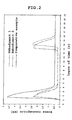
- Fig. 2 shows the power consumption when either one of the rotary shaft 31 a (embodiment 1) and the rotary shaft 31 b (embodiment 2) of the two rotary shafts 31a, 31b is started upon start, and the other rotary shaft 31 b (embodiment 1) or the rotary shaft 31 a (embodiment 2) is started after the rotary drive state of this rotary shaft 31 a or rotary shaft 31b is transferred to a stationary state, or when the both rotary shafts 31a, 31b are started (comparative example) simultaneously upon start.
- start of other rotary shaft 31b (embodiment 1) or rotary shaft 31a (embodiment 2) takes place 12 seconds after start of one rotary shaft 31 a (embodiment 1) or rotary shaft 31 b (embodiment 2).
- embodiment 1 and 2 as compared with the comparative example can reduce the peak capacity (power consumption) of the motor required for rotating and driving the two rotary shafts 31 a, 31 b (that is, the peak capacity of the motors of embodiments 1 and 2 is about 55% of the comparative example), and at the same time, the power consumption of the motors can be reduced.
- the motors Ma, Mb can be naturally synchronized in a specified relative phase state.
- the two motors Ma, Mb are can be started at a specific time difference (12 seconds in the embodiment).
- the vibration generating device 3 has motors Ma, Mb disposed so that the two rotary shafts 31 a, 31 b may be driven independently, and has the rotary drive control mechanism (not shown) constituted so as to stop transmission of rotary drive force to either one of the two rotary shafts 31 a, 31 b upon transfer of the two rotary shafts 31 a, 31 b to a stationary state, and to rotate the rotary motor having stopped the transmission of the rotary drive force in cooperation with the other rotary shaft having stopped the transmission of the rotary drive force.
- the rotary drive control mechanism not shown
- the expression "when the rotary drive state of the rotary shaft is transferred to a stationary state” refers to a moment of reaching the state when the power consumption of the motor suddenly elevates after start of one rotary shaft, then declines gradually until the rotating speed reaches a predetermined speed, thereby converging on a nearly specific value.
- induction motors for motors Ma, Mb Using induction motors for motors Ma, Mb, a specific embodiment is explained herein on a basis of a more specific embodiment, in which two rotary shafts 31 a, 31 b are independently driven in reverse directions.
- the sieving operation of the vibratory sieving machine 1 in addition to the reduction of power consumption of motors Ma, Mb, owing to the difference in the angle of vibrating direction, the sieving operation of the vibratory sieving machine 1 can be selected, so that the sieving efficiency may be enhanced.
- the convey prior sieving operation of [conveying force > sieving force] is executed, and while performing the transportation of the object W supplied on the sieving net 2 of the vibratory sieving machine 1, periodically, and operation is changed over to the operating method of embodiment 4 (in this case, as required, the operation may be interrupted by the operating method of driving the two rotary shafts 31 a, 31 b), and by conducting the sieving prior sieving operation of [sieving force > conveying force], it is possible to sieve by applying a large vibration on the work W by way of the sieving net 2.
- the operating method of embodiment 4 causes the angle of the vibrating direction to be closer to the perpendicular direction (55° to the horizontal plane), it is effective to function to maintain the sieving function of the sieving net 2 by poking into the meshes of the sieving net 2, or scraping off the object W of the broken meshes by vibrations.
- Stopping of either one of the two motors Ma, Mb may be done either continuously or intermittently.
- the two rotary shafts 31 a, 31 b may be started simultaneously, but, instead, upon start, either one rotary shaft of the two rotary shafts 31 a, 31 b may be started, and the other rotary shaft may be started after the rotary drive state of this rotary shaft is transferred to a stationary state.
- the angle of the vibrating direction may be set at an arbitrary angle by adjusting the angle formed by the plane including the central axis of the two rotary shafts 31a, 31 b, with the horizontal plane, for example, at ⁇ 15°, ⁇ 30° across 45° to the horizontal plane.
- the period of generation of vibration may be set in an arbitrary period depending on the rotating speed of the two rotary shafts 31 a, 31b (specifically by the rotating speed of the two motors Ma, Mb).
- Traces of generated vibrating directions may be either linear, or elliptical, for example, by providing with a difference in the mass or the eccentric amount of the eccentric spindles 32a, 32b of the two rotary shafts 31 a, 31 b.
- eccentric spindles usually, semicircular eccentric spindles or circular eccentric spindles having the rotary axis deviated from the center as shown in Fig. 6 (a-1) are widely used, or as shown in Fig. 6 (a-2) or (a-3), rectangular eccentric spindles may be also used.
- the rectangular eccentric spindles shown in Fig. 6 (a-2) and (a-3) is capable of reducing the capacity of the peak of the motor required for starting the rotary shaft as compared with the semicircular eccentric spindle shown in Fig. 6 (a-1), so that it is found that the power consumption of the motor can be decreased.
- Table 1 Eccentric spindle Starting peak power (ratio to eccentric spindle 1) [%] Eccentric spindle 1 (semicircular) 100 Eccentric spindle 2 (rectangular) 91 Eccentric spindle 3 (rectangular) 93
- lubricating oil Oi is reserved in a casing 34 accommodating the eccentric spindles 32a, 32b, and this lubricating oil Oi is sprinkled over the bearings 32a, 32b by scooping up in synchronism with the rotation of the rotary shaft 31b by a cylindrical lubricating oil collar 35 affixed on the rotary shaft 31b.
- this lubricating method has a problem of causing an energy loss due to generation of resistance force while the lubricating oil collar 35 moves in the reserved lubricating oil Oi.
- Fig. 8 it may be designed to supply lubricating oil Oi into the bearings 33a, 33b of the rotary shafts 31a, 31b by way of a vibratory pump 42 from the reservoir unit 41 of lubricating oil Oi, so that the lubricating oil Oi supplied in the bearings 33a, 33b may be sent back to the reservoir unit 41, by way of a strainer 43 for removing foreign matter in the casing 34 and in the lubricating oil Oi.
- the vibratory pump 42 is provided with, as shown in Fig. 9 , a valve disk 42a moved by receiving vibrations in the inside, and therefore the lubricating oil Oi reserved in the reservoir unit 41 is sent out intermittently from onside to other by the valve disk 42a moved reciprocally by receiving the vibration generated by the vibration generation device 3, and is thereby supplied into the bearings 33a, 33b.
- the lubricating oil Oi can be supplied into the bearings 33a, 33b of the rotary shafts 31a, 31b by using the vibration generated by the vibration generation device 3,
- the vibration generation device of the invention is specifically described, and examples of the vibratory sieving machines according to the vibration generation device are also described, but it must be noted that the invention is not limited to the constitution described in these examples or embodiments, but may be changed and modified in various forms within a scope not departing from the true spirit thereof, for example, the constitution comprising plural sets of the vibration generation device of the invention having two rotary shafts provided with eccentric spindles disposed parallel to each other, the plural sets of vibration generation device having common motors, and others.
- the vibration generation device of the invention is a vibration generation device having two rotary shafts provided with eccentric spindles disposed parallel to each other, in which the capacity and power consumption of the motors required herein can be decreased, and hence it is suitable for applications as vibratory sieving machine or vibratory piling machine, and it is widely usable in applications of vibration generation devices.
Landscapes
- Engineering & Computer Science (AREA)
- Mechanical Engineering (AREA)
- Power Engineering (AREA)
- Apparatuses For Generation Of Mechanical Vibrations (AREA)
- Combined Means For Separation Of Solids (AREA)
- Connection Of Motors, Electrical Generators, Mechanical Devices, And The Like (AREA)
- Wind Motors (AREA)
Abstract
Description
- The present invention relates to a vibration generating apparatus, and more particularly to a vibration generating apparatus having two rotary shafts each provided with an eccentric spindle disposed parallel to each other.
- Conventionally, in the vibration generating machine or vibratory pile driving machine of this type, or the like, it has been general to use a vibration generating machine designed to generate vibrations by rotating rotary shafts having eccentric spindles (see, for example,
- Incidentally, it is realized by various mechanisms as disclosed, for example, such as the one having one rotary shaft provided with a eccentric spindle as disclosed in
Patent Document 1, or the one having two rotary shafts parallel to each other having eccentric spindles as disclosed inPatent Document 2, or the one having a plurality of sets thereof - The mechanism having two rotary shafts provided with eccentric spindle disposed parallel to each other is capable of setting the direction of vibration to be generated in a desired direction, and for example, in the mechanism disclosed in
Patent Document 2, by cancelling the vibrations in the horizontal direction between two rotary shafts, it is intended to generate the vibration in the perpendicular direction only. -
- Patent Document 1: Japanese Laid-Open Patent Publication
2003-300019 - Patent Document2: Japanese Laid-Open Patent Publication
10-18288 - For instance, the vibration generating machine having two rotary shafts provided with eccentric spindles disposed parallel to each other has an advantage of determining the direction of the vibration to be generated in a specific direction, but is known to have problems of increasing the motor capacity and the power consumption required to rotate and drive the two rotary shafts provided with eccentric spindles.
- The present invention relates to the problems of the conventional vibration generating machine having two rotary shafts provided with eccentric spindles disposed parallel to each other, and it is a primary object thereof to present a vibration generating machine capable of reducing the required motor capacity or the power consumption. Means for Solving the Problems
- In order to achieve the object, the vibration generating machine in a first aspect of the invention relates to a vibration generating machine having two rotary shafts provided with eccentric spindles disposed parallel to each other, in which motors are disposed so that the two rotary shafts may be driven independently, and a rotary drive control mechanism is constituted so that either one of the two rotary shafts is started upon start, while the other rotary shaft is started after the rotary drive state of this rotary shaft is transferred to a stationary state.
- Herein, the expression that after the rotary drive state of this rotary shaft is transferred to a stationary state refers to the moment of reaching the state when the power consumption of the motor suddenly elevates when one rotary shaft is started, and then declines gradually, and converges on a nearly constant value when the rotating speed reaches a predetermined rotating speed.
- To achieve the same object, the vibration generating machine in a second aspect of the invention relates to a vibration generating machine having two rotary shafts provided with eccentric spindles disposed parallel to each other, in which motors are disposed so that the two rotary shafts may be driven independently, and a rotary drive control mechanism is constituted so that transmission of rotary drive force to either one of the two rotary shafts is suspended after the rotary drive state of the two rotary shafts is transferred to a stationary state, and that the rotary shaft having suspended the transmission of the rotary drive force is rotated along with cooperation of the other rotary shaft vibrated by the generation of the rotary drive of the other rotary shaft.
- Herein, the expression that after the rotary drive state of this rotary shaft is transferred to a stationary state refers to the moment of reaching the state when the power consumption of the motor suddenly elevates when the rotary shaft is started, and then declines gradually, and converges on a nearly constant value when the rotating speed reaches a predetermined rotating speed.
- In this case, selection of the rotary shaft for suspending transmission of rotary drive force may cause to create a difference in the angle of vibrating direction.
- As the eccentric spindle, a rectangular eccentric spindle may be used.
- It is also possible to supply lubricating oil into the bearing of the rotary shaft from the reserve unit of the lubricating oil by way of a vibration pump.
- According to the vibration generating machine of the first aspect of the invention, in the vibration generating machine having two rotary shafts each provided with an eccentric spindle disposed parallel to each other, motors are disposed so that the two rotary shafts may be driven independently, and a rotary drive control mechanism is constituted so that transmission of rotary drive force to either one of the two rotary shafts is suspended after the rotary drive state of the two rotary shafts is transferred to a stationary state, and that the rotary shaft having suspended the transmission of the rotary drive force is rotated along with cooperation of the other rotary shaft vibrated by the generation of the rotary drive of the other rotary shaft, and therefore the power consumption of the motors is saved.
- According to the vibration generating machine of the second aspect of the invention, in the vibration generating machine having two rotary shafts each provided with an eccentric spindle disposed parallel to each other, motors are disposed so that the two rotary shafts may be driven independently, and a rotary drive control mechanism is constituted so that transmission of rotary drive force to either one of the two rotary shafts is suspended after the rotary drive state of the two rotary shafts is transferred to a stationary state, and that the rotary shaft having suspended the transmission of the rotary drive force is rotated along with cooperation of the other rotary shaft vibrated by the generation of the rotary drive of the other rotary shaft, and therefore
- By selection of the rotary shaft for suspending transmission of rotary drive force, it may cause to create a difference in the angle of vibrating direction, and therefore in the vibratory sieving machine, for example, the transfer prior sieving operation and the sieving prior sieving operation can be selectively done, so that the sieving operation may be done efficiently.
- As the eccentric spindle, by using a rectangular eccentric spindle, as compared with the semicircular eccentric spindle conventionally used widely, the volume of the peak of the motor required to start the rotary shaft can be reduced, and selection of the rotary shaft for suspending transmission of rotary drive force may cause to create a difference in the angle of vibrating direction.
- By supplying lubricating oil into the bearing of the rotary shaft from the reserve unit of the lubricating oil by way of a vibration pump, without requiring another power source, the vibration generated by the vibration generating machine can be used as the driving source, and the lubricating oil can be supplied to the bearing of the rotary shaft. Hence there is no energy loss in the case of supplying the lubricating oil by using a lubricating oil collar, and the power consumption of the motor can be saved.
-
-
Fig. 1 is a front view showing an embodiment of a vibratory sieving machine according to the vibration generating machine of the invention. -
Fig. 2 is a graph showing an exemplary embodiment of the first aspect of the invention, and a comparative example. -
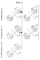
Fig. 3 is an explanatory diagram showing an exemplary embodiment of the second aspect of the invention. -
Fig. 4 is a graph showing the relationship between rotating speed and power consumption of a motor. -
Fig. 5 is a graph showing the relationship between traces of vibrating direction and power consumption. -
Fig. 6 (a-1) to (a-3) are exemplary diagrams showing shapes of various eccentric spindles, and (b) is a graph showing the relationship between the eccentric spindles and power consumption. -
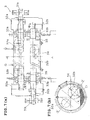
Fig. 7 is an explanatory diagram showing an example of using a lubricating oil collar in the mechanism for supplying lubricating oil into the bearing of the rotary shaft by using a vibratory pump, in which (a) is a longitudinal sectional view (B-B section diagram of (b)), and (b) is a lateral sectional view (A-A section diagram of (a)). -
Fig. 8 is an explanatory diagram showing an example of using a vibratory pump in the mechanism for supplying lubricating oil into the bearing of the rotary shaft by using a vibratory pump. -
Fig. 9 is an explanatory diagram of a vibratory pump, in which (a) is a sectional view of the vibratory pump, (b-1) is a plan view of a valve disc of the vibratory pump, (b-2) is a front view thereof, and (c) is a stroke explanatory diagram of the vibratory pump. -
Fig. 10 is a graph showing the relationship of power consumption when using a lubricating oil collar and a vibratory pump. Best Mode for Carrying Out the Invention - Hereinafter, an embodiment of the vibration generating machine of the invention is described specifically while referring to the accompanying drawings.
-
Fig. 1 shows an example of a vibratory sieving machine according to the vibration generating machine of the present invention. - This
vibratory sieving machine 1 is designed to convey the object W supplied on asieving net 2 while vibrating and sieving through thesieving net 2, and it comprises a vibration generatingdevice 3 having tworotary shafts eccentric spindles sieving net 2. - The vibration generating
device 3 has motors Ma, Mb disposed so that the tworotary shafts rotary shafts - Herein, the expression "when the rotary drive state of the rotary shaft is transferred to a stationary state" refers to a moment of reaching the state when the power consumption of the motor suddenly elevates after start of one rotary shaft, then declines gradually until the rotating speed reaches a predetermined speed, thereby converging on a nearly specific value.
- Using induction motors for motors Ma, Mb, a specific embodiment is explained herein on a basis of a more specific embodiment, in which two
rotary shafts -
Fig. 2 shows the power consumption when either one of therotary shaft 31 a (embodiment 1) and therotary shaft 31 b (embodiment 2) of the tworotary shafts rotary shaft 31 b (embodiment 1) or therotary shaft 31 a (embodiment 2) is started after the rotary drive state of thisrotary shaft 31 a orrotary shaft 31b is transferred to a stationary state, or when the bothrotary shafts - In
Fig. 2 , start of otherrotary shaft 31b (embodiment 1) orrotary shaft 31a (embodiment 2) takesplace 12 seconds after start of onerotary shaft 31 a (embodiment 1) orrotary shaft 31 b (embodiment 2). - As clear from
Fig. 2 , it is known thatembodiment rotary shafts embodiments - Meanwhile, if the two motors Ma, Mb are started without synchronism, by the generated vibrations, the motors Ma, Mb can be naturally synchronized in a specified relative phase state.
- Accordingly, as the rotary drive control device, by using simple relay circuits or timer circuits, the two motors Ma, Mb are can be started at a specific time difference (12 seconds in the embodiment).
- On the other hand, the vibration generating
device 3 has motors Ma, Mb disposed so that the tworotary shafts rotary shafts rotary shafts - Herein, the expression "when the rotary drive state of the rotary shaft is transferred to a stationary state" refers to a moment of reaching the state when the power consumption of the motor suddenly elevates after start of one rotary shaft, then declines gradually until the rotating speed reaches a predetermined speed, thereby converging on a nearly specific value.
- Using induction motors for motors Ma, Mb, a specific embodiment is explained herein on a basis of a more specific embodiment, in which two
rotary shafts - In
Fig. 3 , after the rotary drive state of the tworotary shafts rotary shafts 31b (embodiment 3) orrotary shaft 31a (embodiment 4) out of the tworotary shafts rotary shaft 31b orrotary shaft 31a having stopped the transmission of the rotary drive force is rotated in cooperation with the otherrotary shaft 31a orrotary shaft 31b by the vibration generated by rotary drive of therotary shaft 31a orrotary shaft 31 b due to other motor Ma or motor Mb. - As shown in
Fig. 3 , as compared with the angle of the vibrating direction being in a stationary state (45° to the horizontal plane) of the rotary drive state of the tworotary shafts embodiment 3, since therotary shaft 31b having stopped the transmission of rotary drive force is rotated along behind therotary shaft 31b being rotated and driven, and thereby approaching the horizontal direction (35° to the horizontal plane), and therefore in the case ofembodiment 4, since therotary shaft 31a having stopped transmission of the rotary drive force is rotated along behind the rotated and drivenrotary shaft 31 b, and thereby approaches in the vertical direction (55° to the horizontal plane). - It is therefore known that the power consumption of the motors Ma, Mb can be decreased by about 15% as compared with the conventional case of rotating and driving the two
rotary shafts - In the operating method of
embodiment 3 andembodiment 4, in addition to the reduction of power consumption of motors Ma, Mb, owing to the difference in the angle of vibrating direction, the sieving operation of thevibratory sieving machine 1 can be selected, so that the sieving efficiency may be enhanced. - In other words, in the operating method of
embodiment 3, since the angle of the vibrating direction is closer to the horizontal direction (35° to the horizontal plane), as compared with the stationary state (45° to the horizontal plane), the sieving operation is in the relation of [conveying force > sieving force], whereas in the operating method ofembodiment 4, since the angle of the vibrating direction is closer to the horizontal direction (55° to the horizontal plane), as compared with the stationary state (45° to the horizontal plane), the sieving operation is in the relation of [sieving force] > [conveying force]. - Incidentally, by making use of difference in the sieving operation due to the angle of the vibrating direction, for example, after the rotary drive state of the two
rotary shafts embodiment 3, the convey prior sieving operation of [conveying force > sieving force] is executed, and while performing the transportation of the object W supplied on thesieving net 2 of thevibratory sieving machine 1, periodically, and operation is changed over to the operating method of embodiment 4 (in this case, as required, the operation may be interrupted by the operating method of driving the tworotary shafts sieving net 2. - Since the operating method of
embodiment 4 causes the angle of the vibrating direction to be closer to the perpendicular direction (55° to the horizontal plane), it is effective to function to maintain the sieving function of thesieving net 2 by poking into the meshes of thesieving net 2, or scraping off the object W of the broken meshes by vibrations. - Herein, it is enough to stop either one of the two motors Ma, Mb, as the rotary drive control mechanism, simple relay circuits or timer circuits may be used, and driving of the two motors Ma, Mb may be controlled.
- Stopping of either one of the two motors Ma, Mb may be done either continuously or intermittently.
- As shown in
Fig. 3 , meanwhile, as for the angle of the vibrating direction, in order to maintain the rotary drive state of the tworotary shafts rotary shafts rotary shafts - Incidentally, the angle of the vibrating direction may be set at an arbitrary angle by adjusting the angle formed by the plane including the central axis of the two
rotary shafts - The period of generation of vibration may be set in an arbitrary period depending on the rotating speed of the two
rotary shafts - Herein, as shown in
Fig. 4 , a positive phase relationship is established among the rotating speed and power consumption of the two motors Ma, Mb. - Traces of generated vibrating directions may be either linear, or elliptical, for example, by providing with a difference in the mass or the eccentric amount of the
eccentric spindles rotary shafts - Herein, as clarified by the relation between the traces of the vibrating diction being generated and the power consumption shown in
Fig. 5 , it is learned that the power consumption is smaller in the elliptical profile than in the linear profile (about 7% upon start (peak) of the rotary shaft, about 2% upon migration of the rotary drive state of the rotary shaft to a stationary state.) - As eccentric spindles, usually, semicircular eccentric spindles or circular eccentric spindles having the rotary axis deviated from the center as shown in
Fig. 6 (a-1) are widely used, or as shown inFig. 6 (a-2) or (a-3), rectangular eccentric spindles may be also used. - Further, referring to Table 1 and
Fig. 6 (b) , as evident from the results of the experiment conducted by using eccentric spindles having the magnitude of the vibration to be generated at same values, the rectangular eccentric spindles shown inFig. 6 (a-2) and (a-3) is capable of reducing the capacity of the peak of the motor required for starting the rotary shaft as compared with the semicircular eccentric spindle shown inFig. 6 (a-1), so that it is found that the power consumption of the motor can be decreased.Table 1 Eccentric spindle Starting peak power (ratio to eccentric spindle 1) [%] Eccentric spindle 1 (semicircular) 100 Eccentric spindle 2 (rectangular) 91 Eccentric spindle 3 (rectangular) 93 - Incidentally, as shown in
Fig. 7 , in the vibration generating device of this kind, for lubrication of thebearings rotary shafts eccentric spindles casing 34 accommodating theeccentric spindles bearings rotary shaft 31b by a cylindricallubricating oil collar 35 affixed on therotary shaft 31b. - However, this lubricating method has a problem of causing an energy loss due to generation of resistance force while the lubricating
oil collar 35 moves in the reserved lubricating oil Oi. - To cope with this problem, as shown in
Fig. 8 , it may be designed to supply lubricating oil Oi into thebearings rotary shafts vibratory pump 42 from thereservoir unit 41 of lubricating oil Oi, so that the lubricating oil Oi supplied in thebearings reservoir unit 41, by way of astrainer 43 for removing foreign matter in thecasing 34 and in the lubricating oil Oi. - Herein, the
vibratory pump 42 is provided with, as shown inFig. 9 , avalve disk 42a moved by receiving vibrations in the inside, and therefore the lubricating oil Oi reserved in thereservoir unit 41 is sent out intermittently from onside to other by thevalve disk 42a moved reciprocally by receiving the vibration generated by thevibration generation device 3, and is thereby supplied into thebearings - As a result, without requiring another driving source, the lubricating oil Oi can be supplied into the
bearings rotary shafts vibration generation device 3, - Then, as clear from the results of experiment using the lubricating oil collar and the vibratory pump shown in
Fig. 10 , when using the vibratory pump, as compared with the case of using lubricating oil collar, it is found possible to reduce the power consumption of the motor consumed for rotating and driving the rotary shaft in a stationary state. - Herein, the vibration generation device of the invention is specifically described, and examples of the vibratory sieving machines according to the vibration generation device are also described, but it must be noted that the invention is not limited to the constitution described in these examples or embodiments, but may be changed and modified in various forms within a scope not departing from the true spirit thereof, for example, the constitution comprising plural sets of the vibration generation device of the invention having two rotary shafts provided with eccentric spindles disposed parallel to each other, the plural sets of vibration generation device having common motors, and others.
- The vibration generation device of the invention is a vibration generation device having two rotary shafts provided with eccentric spindles disposed parallel to each other, in which the capacity and power consumption of the motors required herein can be decreased, and hence it is suitable for applications as vibratory sieving machine or vibratory piling machine, and it is widely usable in applications of vibration generation devices.
-
- 1
- Vibratory sieving machine
- 2
- Sieving net
- 3
- Vibration generation device
- 31a
- Rotary shaft
- 31b
- Rotary shaft
- 32a
- Eccentric spindle
- 32b
- Eccentric spindle
- Ma
- Motor
- Mb
- Motor
- W
- Object
Claims (5)
- A vibration generating machine having two rotary shafts provided with eccentric spindles disposed parallel to each other, wherein motors are disposed so that the two rotary shafts may be driven independently, and a rotary drive control mechanism is constituted so that either one of the two rotary shafts is started upon start, while the other rotary shaft is started after the rotary drive state of this rotary shaft is transferred to a stationary state.
- A vibration generating machine having two rotary shafts provided with eccentric spindles disposed parallel to each other, wherein motors are disposed so that the two rotary shafts may be driven independently, and a rotary drive control mechanism is constituted so that transmission of rotary drive force to either one of the two rotary shafts is suspended after the rotary drive state of the two rotary shafts is transferred to a stationary state, and that the rotary shaft having suspended the transmission of the rotary drive force is rotated along with cooperation of the other rotary shaft vibrated by the generation of the rotary drive of the other rotary shaft.
- The vibration generating machine according to claim 2, wherein selection of the rotary shaft for stopping transmission of rotary drive force has caused difference in the angle of vibrating direction.
- The vibration generating machine according to claim 1, 2, or 3, wherein rectangular eccentric spindles are used for the eccentric spindles.
- The vibration generating machine according to claim 1, 2, 3 or 4, wherein lubricating oil is supplied into the bearings of the rotary shafts from the reservoir unit of the lubricating oil by way of a vibratory pump.
Applications Claiming Priority (2)
| Application Number | Priority Date | Filing Date | Title |
|---|---|---|---|
| JP2013085055 | 2013-04-15 | ||
| PCT/JP2014/060584 WO2014171416A1 (en) | 2013-04-15 | 2014-04-14 | Vibration generation device |
Publications (3)
| Publication Number | Publication Date |
|---|---|
| EP2987563A1 true EP2987563A1 (en) | 2016-02-24 |
| EP2987563A4 EP2987563A4 (en) | 2016-12-14 |
| EP2987563B1 EP2987563B1 (en) | 2021-07-21 |
Family
ID=51731357
Family Applications (1)
| Application Number | Title | Priority Date | Filing Date |
|---|---|---|---|
| EP14785447.5A Active EP2987563B1 (en) | 2013-04-15 | 2014-04-14 | Vibratory sieving machine |
Country Status (8)
| Country | Link |
|---|---|
| US (1) | US10263493B2 (en) |
| EP (1) | EP2987563B1 (en) |
| JP (1) | JP5969115B2 (en) |
| CN (1) | CN105102141B (en) |
| MY (1) | MY175485A (en) |
| PH (1) | PH12015502363B1 (en) |
| SG (1) | SG11201507746WA (en) |
| WO (1) | WO2014171416A1 (en) |
Cited By (1)
| Publication number | Priority date | Publication date | Assignee | Title |
|---|---|---|---|---|
| EP3388156A4 (en) * | 2015-12-08 | 2019-09-25 | Kabushiki Kaisha Kinki | METHOD OF CONTROLLING OPERATION OF VIBRANT TRIM SCREEN |
Families Citing this family (4)
| Publication number | Priority date | Publication date | Assignee | Title |
|---|---|---|---|---|
| US10201398B2 (en) | 2015-03-20 | 2019-02-12 | Kaltenbach & Voigt Gmbh | Dispensing material from a dental handpiece |
| CN108554802B (en) * | 2018-05-22 | 2023-08-01 | 西南石油大学 | A co-rotating multi-excitation motor device coupled with tension springs |
| US11801191B2 (en) * | 2019-12-10 | 2023-10-31 | Performance Health Systems, Llc | Hypotrochoid assembly for generating vibrations in an exercise machine and method for using same |
| JP7757662B2 (en) * | 2021-08-27 | 2025-10-22 | セイコーエプソン株式会社 | Vibration generator, vibration generator control method, and pickup system |
Family Cites Families (17)
| Publication number | Priority date | Publication date | Assignee | Title |
|---|---|---|---|---|
| NL42791C (en) * | ||||
| US3948354A (en) * | 1974-09-18 | 1976-04-06 | Hydrotile Machinery Company | Lubricator for concrete pipe vibrators |
| IT1073972B (en) * | 1975-07-29 | 1985-04-17 | Komatsu Mfg Co Ltd | VARIABLE FORCE VIBRATOR |
| DE2551396A1 (en) * | 1975-11-15 | 1977-05-18 | Licentia Gmbh | Horizontal force component prodn. for vibrating sieve - use two unbalanced motor one switchable to freewheel to change vibration vector |
| US4255254A (en) * | 1979-11-19 | 1981-03-10 | Faunce And Associates, Inc. | Delayed counterweight vibrator apparatus |
| CN85102855B (en) * | 1985-04-01 | 1987-09-23 | 曹培生 | Nonlinear electromagnetic oscillation device |
| US4793196A (en) * | 1987-03-24 | 1988-12-27 | Key Technology, Inc. | Gear coupled, counter-rotating vibratory drive assembly |
| JP2872880B2 (en) * | 1993-04-06 | 1999-03-24 | 調和工業株式会社 | Drive and control method of the exciter |
| CN2154131Y (en) * | 1993-05-04 | 1994-01-26 | 新乡市太行振动机械厂 | Double-axle vibrator |
| JP2790990B2 (en) * | 1995-07-31 | 1998-08-27 | 調和工業株式会社 | Rotary shaker and control method of rotary shaker |
| JP2724296B2 (en) * | 1995-09-14 | 1998-03-09 | 調和工業株式会社 | Excitation weight control method and control mechanism for eccentric weight |
| JP2911408B2 (en) | 1996-07-03 | 1999-06-23 | 株式会社キンキ | Vibratory pile driver with built-in radiator |
| JPH11182414A (en) * | 1997-12-18 | 1999-07-06 | Furukawa Co Ltd | Vibration pump and lubrication device using vibration pump |
| JP2001025293A (en) * | 1999-07-09 | 2001-01-26 | Nippon Signal Co Ltd:The | Motor control device |
| JP4027142B2 (en) | 2002-04-09 | 2007-12-26 | 株式会社キンキ | Vibrating sieve machine and sieve equipment equipped with it |
| TWI280842B (en) * | 2005-11-18 | 2007-05-01 | Delta Electronics Inc | Fan system and sequential starting module and delayed starting unit thereof |
| CN101864772B (en) * | 2010-06-24 | 2012-11-21 | 河海大学常州校区 | Vibrating pile head capable of automatically adjusting eccentric moment and piling efficiency |
-
2014
- 2014-04-14 MY MYPI2015702811A patent/MY175485A/en unknown
- 2014-04-14 SG SG11201507746WA patent/SG11201507746WA/en unknown
- 2014-04-14 US US14/783,098 patent/US10263493B2/en active Active
- 2014-04-14 CN CN201480018653.0A patent/CN105102141B/en active Active
- 2014-04-14 WO PCT/JP2014/060584 patent/WO2014171416A1/en not_active Ceased
- 2014-04-14 JP JP2015512468A patent/JP5969115B2/en active Active
- 2014-04-14 EP EP14785447.5A patent/EP2987563B1/en active Active
-
2015
- 2015-10-12 PH PH12015502363A patent/PH12015502363B1/en unknown
Cited By (1)
| Publication number | Priority date | Publication date | Assignee | Title |
|---|---|---|---|---|
| EP3388156A4 (en) * | 2015-12-08 | 2019-09-25 | Kabushiki Kaisha Kinki | METHOD OF CONTROLLING OPERATION OF VIBRANT TRIM SCREEN |
Also Published As
| Publication number | Publication date |
|---|---|
| JPWO2014171416A1 (en) | 2017-02-23 |
| PH12015502363A1 (en) | 2016-02-22 |
| CN105102141B (en) | 2017-11-14 |
| WO2014171416A1 (en) | 2014-10-23 |
| CN105102141A (en) | 2015-11-25 |
| SG11201507746WA (en) | 2015-10-29 |
| PH12015502363B1 (en) | 2016-02-22 |
| EP2987563B1 (en) | 2021-07-21 |
| US20160056685A1 (en) | 2016-02-25 |
| EP2987563A4 (en) | 2016-12-14 |
| US10263493B2 (en) | 2019-04-16 |
| MY175485A (en) | 2020-06-30 |
| JP5969115B2 (en) | 2016-08-10 |
Similar Documents
| Publication | Publication Date | Title |
|---|---|---|
| EP2987563B1 (en) | Vibratory sieving machine | |
| EA039947B1 (en) | Machine for stabilizing a track | |
| JP6078079B2 (en) | Machine and method for turning a flat shoulder surrounding at least a crankpin of a crankshaft | |
| CN204148131U (en) | Twin axle self-synchronization exciting device | |
| US9038491B2 (en) | Method of repositioning bearing wear in an industrial eccentric weight vibrator via power inversion and vibrator therefore | |
| JP6382457B2 (en) | Operation control method of vibrating screen | |
| JP2015196198A (en) | Tool vibration device for plane machining | |
| CN106000850A (en) | Exciting force adjusting device | |
| CA2570690A1 (en) | Servo stroking apparatus and system | |
| CN108620304B (en) | Slide belt type online variable force vibration exciter | |
| US20150375306A1 (en) | Vibrating System | |
| JP2018187726A (en) | Vibration cutting device and vibration apparatus | |
| CN108044695A (en) | A kind of mechanical torsional oscillation platform based on space cam | |
| KR102620726B1 (en) | machine tools | |
| CN208272784U (en) | A kind of double vibration motors | |
| US20180202522A1 (en) | Vibratory system having an oscillating plate | |
| RU2449875C1 (en) | Method of flat vibration grinding | |
| CN104549980B (en) | Reciprocating oscillation conveyor | |
| RU2449874C1 (en) | Device for surface flat vibrogrinding | |
| RU2516262C2 (en) | Method of starting vibro machine with two autosynchronous unbalance vibration exciters | |
| CN207951959U (en) | A kind of multilayer variation ellipse vibrating screen of four shock electric machines | |
| KR101539620B1 (en) | Lateral vibration generator generating various vibration mode using rotational speed and phase difference | |
| JP5991417B2 (en) | Rotating machine | |
| JP4360987B2 (en) | Vibrator | |
| RU2537103C2 (en) | Vibration unit |
Legal Events
| Date | Code | Title | Description |
|---|---|---|---|
| PUAI | Public reference made under article 153(3) epc to a published international application that has entered the european phase |
Free format text: ORIGINAL CODE: 0009012 |
|
| 17P | Request for examination filed |
Effective date: 20150818 |
|
| AK | Designated contracting states |
Kind code of ref document: A1 Designated state(s): AL AT BE BG CH CY CZ DE DK EE ES FI FR GB GR HR HU IE IS IT LI LT LU LV MC MK MT NL NO PL PT RO RS SE SI SK SM TR |
|
| AX | Request for extension of the european patent |
Extension state: BA ME |
|
| DAX | Request for extension of the european patent (deleted) | ||
| A4 | Supplementary search report drawn up and despatched |
Effective date: 20161115 |
|
| RIC1 | Information provided on ipc code assigned before grant |
Ipc: E02D 7/18 20060101ALI20161109BHEP Ipc: B07B 1/42 20060101ALI20161109BHEP Ipc: B06B 1/16 20060101AFI20161109BHEP |
|
| STAA | Information on the status of an ep patent application or granted ep patent |
Free format text: STATUS: EXAMINATION IS IN PROGRESS |
|
| 17Q | First examination report despatched |
Effective date: 20201015 |
|
| GRAP | Despatch of communication of intention to grant a patent |
Free format text: ORIGINAL CODE: EPIDOSNIGR1 |
|
| STAA | Information on the status of an ep patent application or granted ep patent |
Free format text: STATUS: GRANT OF PATENT IS INTENDED |
|
| INTG | Intention to grant announced |
Effective date: 20210506 |
|
| GRAS | Grant fee paid |
Free format text: ORIGINAL CODE: EPIDOSNIGR3 |
|
| GRAA | (expected) grant |
Free format text: ORIGINAL CODE: 0009210 |
|
| STAA | Information on the status of an ep patent application or granted ep patent |
Free format text: STATUS: THE PATENT HAS BEEN GRANTED |
|
| AK | Designated contracting states |
Kind code of ref document: B1 Designated state(s): AL AT BE BG CH CY CZ DE DK EE ES FI FR GB GR HR HU IE IS IT LI LT LU LV MC MK MT NL NO PL PT RO RS SE SI SK SM TR |
|
| REG | Reference to a national code |
Ref country code: GB Ref legal event code: FG4D |
|
| REG | Reference to a national code |
Ref country code: CH Ref legal event code: EP |
|
| REG | Reference to a national code |
Ref country code: DE Ref legal event code: R096 Ref document number: 602014078914 Country of ref document: DE |
|
| REG | Reference to a national code |
Ref country code: AT Ref legal event code: REF Ref document number: 1412112 Country of ref document: AT Kind code of ref document: T Effective date: 20210815 |
|
| REG | Reference to a national code |
Ref country code: IE Ref legal event code: FG4D |
|
| REG | Reference to a national code |
Ref country code: NL Ref legal event code: FP |
|
| REG | Reference to a national code |
Ref country code: LT Ref legal event code: MG9D |
|
| REG | Reference to a national code |
Ref country code: AT Ref legal event code: MK05 Ref document number: 1412112 Country of ref document: AT Kind code of ref document: T Effective date: 20210721 |
|
| PG25 | Lapsed in a contracting state [announced via postgrant information from national office to epo] |
Ref country code: NO Free format text: LAPSE BECAUSE OF FAILURE TO SUBMIT A TRANSLATION OF THE DESCRIPTION OR TO PAY THE FEE WITHIN THE PRESCRIBED TIME-LIMIT Effective date: 20211021 Ref country code: PT Free format text: LAPSE BECAUSE OF FAILURE TO SUBMIT A TRANSLATION OF THE DESCRIPTION OR TO PAY THE FEE WITHIN THE PRESCRIBED TIME-LIMIT Effective date: 20211122 Ref country code: FI Free format text: LAPSE BECAUSE OF FAILURE TO SUBMIT A TRANSLATION OF THE DESCRIPTION OR TO PAY THE FEE WITHIN THE PRESCRIBED TIME-LIMIT Effective date: 20210721 Ref country code: ES Free format text: LAPSE BECAUSE OF FAILURE TO SUBMIT A TRANSLATION OF THE DESCRIPTION OR TO PAY THE FEE WITHIN THE PRESCRIBED TIME-LIMIT Effective date: 20210721 Ref country code: BG Free format text: LAPSE BECAUSE OF FAILURE TO SUBMIT A TRANSLATION OF THE DESCRIPTION OR TO PAY THE FEE WITHIN THE PRESCRIBED TIME-LIMIT Effective date: 20211021 Ref country code: AT Free format text: LAPSE BECAUSE OF FAILURE TO SUBMIT A TRANSLATION OF THE DESCRIPTION OR TO PAY THE FEE WITHIN THE PRESCRIBED TIME-LIMIT Effective date: 20210721 Ref country code: LT Free format text: LAPSE BECAUSE OF FAILURE TO SUBMIT A TRANSLATION OF THE DESCRIPTION OR TO PAY THE FEE WITHIN THE PRESCRIBED TIME-LIMIT Effective date: 20210721 Ref country code: RS Free format text: LAPSE BECAUSE OF FAILURE TO SUBMIT A TRANSLATION OF THE DESCRIPTION OR TO PAY THE FEE WITHIN THE PRESCRIBED TIME-LIMIT Effective date: 20210721 Ref country code: SE Free format text: LAPSE BECAUSE OF FAILURE TO SUBMIT A TRANSLATION OF THE DESCRIPTION OR TO PAY THE FEE WITHIN THE PRESCRIBED TIME-LIMIT Effective date: 20210721 Ref country code: HR Free format text: LAPSE BECAUSE OF FAILURE TO SUBMIT A TRANSLATION OF THE DESCRIPTION OR TO PAY THE FEE WITHIN THE PRESCRIBED TIME-LIMIT Effective date: 20210721 |
|
| PG25 | Lapsed in a contracting state [announced via postgrant information from national office to epo] |
Ref country code: PL Free format text: LAPSE BECAUSE OF FAILURE TO SUBMIT A TRANSLATION OF THE DESCRIPTION OR TO PAY THE FEE WITHIN THE PRESCRIBED TIME-LIMIT Effective date: 20210721 Ref country code: LV Free format text: LAPSE BECAUSE OF FAILURE TO SUBMIT A TRANSLATION OF THE DESCRIPTION OR TO PAY THE FEE WITHIN THE PRESCRIBED TIME-LIMIT Effective date: 20210721 Ref country code: GR Free format text: LAPSE BECAUSE OF FAILURE TO SUBMIT A TRANSLATION OF THE DESCRIPTION OR TO PAY THE FEE WITHIN THE PRESCRIBED TIME-LIMIT Effective date: 20211022 |
|
| REG | Reference to a national code |
Ref country code: DE Ref legal event code: R097 Ref document number: 602014078914 Country of ref document: DE |
|
| PG25 | Lapsed in a contracting state [announced via postgrant information from national office to epo] |
Ref country code: DK Free format text: LAPSE BECAUSE OF FAILURE TO SUBMIT A TRANSLATION OF THE DESCRIPTION OR TO PAY THE FEE WITHIN THE PRESCRIBED TIME-LIMIT Effective date: 20210721 |
|
| PLBE | No opposition filed within time limit |
Free format text: ORIGINAL CODE: 0009261 |
|
| STAA | Information on the status of an ep patent application or granted ep patent |
Free format text: STATUS: NO OPPOSITION FILED WITHIN TIME LIMIT |
|
| PG25 | Lapsed in a contracting state [announced via postgrant information from national office to epo] |
Ref country code: SM Free format text: LAPSE BECAUSE OF FAILURE TO SUBMIT A TRANSLATION OF THE DESCRIPTION OR TO PAY THE FEE WITHIN THE PRESCRIBED TIME-LIMIT Effective date: 20210721 Ref country code: SK Free format text: LAPSE BECAUSE OF FAILURE TO SUBMIT A TRANSLATION OF THE DESCRIPTION OR TO PAY THE FEE WITHIN THE PRESCRIBED TIME-LIMIT Effective date: 20210721 Ref country code: RO Free format text: LAPSE BECAUSE OF FAILURE TO SUBMIT A TRANSLATION OF THE DESCRIPTION OR TO PAY THE FEE WITHIN THE PRESCRIBED TIME-LIMIT Effective date: 20210721 Ref country code: EE Free format text: LAPSE BECAUSE OF FAILURE TO SUBMIT A TRANSLATION OF THE DESCRIPTION OR TO PAY THE FEE WITHIN THE PRESCRIBED TIME-LIMIT Effective date: 20210721 Ref country code: CZ Free format text: LAPSE BECAUSE OF FAILURE TO SUBMIT A TRANSLATION OF THE DESCRIPTION OR TO PAY THE FEE WITHIN THE PRESCRIBED TIME-LIMIT Effective date: 20210721 Ref country code: AL Free format text: LAPSE BECAUSE OF FAILURE TO SUBMIT A TRANSLATION OF THE DESCRIPTION OR TO PAY THE FEE WITHIN THE PRESCRIBED TIME-LIMIT Effective date: 20210721 |
|
| 26N | No opposition filed |
Effective date: 20220422 |
|
| REG | Reference to a national code |
Ref country code: BE Ref legal event code: MM Effective date: 20220430 |
|
| PG25 | Lapsed in a contracting state [announced via postgrant information from national office to epo] |
Ref country code: MC Free format text: LAPSE BECAUSE OF FAILURE TO SUBMIT A TRANSLATION OF THE DESCRIPTION OR TO PAY THE FEE WITHIN THE PRESCRIBED TIME-LIMIT Effective date: 20210721 Ref country code: LU Free format text: LAPSE BECAUSE OF NON-PAYMENT OF DUE FEES Effective date: 20220414 |
|
| PG25 | Lapsed in a contracting state [announced via postgrant information from national office to epo] |
Ref country code: BE Free format text: LAPSE BECAUSE OF NON-PAYMENT OF DUE FEES Effective date: 20220430 |
|
| PG25 | Lapsed in a contracting state [announced via postgrant information from national office to epo] |
Ref country code: IE Free format text: LAPSE BECAUSE OF NON-PAYMENT OF DUE FEES Effective date: 20220414 |
|
| PG25 | Lapsed in a contracting state [announced via postgrant information from national office to epo] |
Ref country code: HU Free format text: LAPSE BECAUSE OF FAILURE TO SUBMIT A TRANSLATION OF THE DESCRIPTION OR TO PAY THE FEE WITHIN THE PRESCRIBED TIME-LIMIT; INVALID AB INITIO Effective date: 20140414 |
|
| PG25 | Lapsed in a contracting state [announced via postgrant information from national office to epo] |
Ref country code: MK Free format text: LAPSE BECAUSE OF FAILURE TO SUBMIT A TRANSLATION OF THE DESCRIPTION OR TO PAY THE FEE WITHIN THE PRESCRIBED TIME-LIMIT Effective date: 20210721 Ref country code: CY Free format text: LAPSE BECAUSE OF FAILURE TO SUBMIT A TRANSLATION OF THE DESCRIPTION OR TO PAY THE FEE WITHIN THE PRESCRIBED TIME-LIMIT Effective date: 20210721 |
|
| PG25 | Lapsed in a contracting state [announced via postgrant information from national office to epo] |
Ref country code: TR Free format text: LAPSE BECAUSE OF FAILURE TO SUBMIT A TRANSLATION OF THE DESCRIPTION OR TO PAY THE FEE WITHIN THE PRESCRIBED TIME-LIMIT Effective date: 20210721 |
|
| PG25 | Lapsed in a contracting state [announced via postgrant information from national office to epo] |
Ref country code: MT Free format text: LAPSE BECAUSE OF FAILURE TO SUBMIT A TRANSLATION OF THE DESCRIPTION OR TO PAY THE FEE WITHIN THE PRESCRIBED TIME-LIMIT Effective date: 20210721 |
|
| PGFP | Annual fee paid to national office [announced via postgrant information from national office to epo] |
Ref country code: GB Payment date: 20260325 Year of fee payment: 13 |
|
| PGFP | Annual fee paid to national office [announced via postgrant information from national office to epo] |
Ref country code: IT Payment date: 20260324 Year of fee payment: 13 |
|
| PGFP | Annual fee paid to national office [announced via postgrant information from national office to epo] |
Ref country code: NL Payment date: 20260327 Year of fee payment: 13 |
|
| REG | Reference to a national code |
Ref country code: CH Ref legal event code: U11 Free format text: ST27 STATUS EVENT CODE: U-0-0-U10-U11 (AS PROVIDED BY THE NATIONAL OFFICE) Effective date: 20260501 |
|
| PGFP | Annual fee paid to national office [announced via postgrant information from national office to epo] |
Ref country code: DE Payment date: 20260326 Year of fee payment: 13 |
|
| PGFP | Annual fee paid to national office [announced via postgrant information from national office to epo] |
Ref country code: CH Payment date: 20260501 Year of fee payment: 13 |
|
| PGFP | Annual fee paid to national office [announced via postgrant information from national office to epo] |
Ref country code: FR Payment date: 20260420 Year of fee payment: 13 |