EP2987550A1 - Method and system for NOx removal - Google Patents
Method and system for NOx removal Download PDFInfo
- Publication number
- EP2987550A1 EP2987550A1 EP14181291.7A EP14181291A EP2987550A1 EP 2987550 A1 EP2987550 A1 EP 2987550A1 EP 14181291 A EP14181291 A EP 14181291A EP 2987550 A1 EP2987550 A1 EP 2987550A1
- Authority
- EP
- European Patent Office
- Prior art keywords
- flue gas
- reagent
- oxidizer
- removal
- supply
- Prior art date
- Legal status (The legal status is an assumption and is not a legal conclusion. Google has not performed a legal analysis and makes no representation as to the accuracy of the status listed.)
- Granted
Links
Images
Classifications
-
- B—PERFORMING OPERATIONS; TRANSPORTING
- B01—PHYSICAL OR CHEMICAL PROCESSES OR APPARATUS IN GENERAL
- B01D—SEPARATION
- B01D53/00—Separation of gases or vapours; Recovering vapours of volatile solvents from gases; Chemical or biological purification of waste gases, e.g. engine exhaust gases, smoke, fumes, flue gases, aerosols
- B01D53/34—Chemical or biological purification of waste gases
- B01D53/74—General processes for purification of waste gases; Apparatus or devices specially adapted therefor
- B01D53/77—Liquid phase processes
- B01D53/78—Liquid phase processes with gas-liquid contact
-
- B—PERFORMING OPERATIONS; TRANSPORTING
- B01—PHYSICAL OR CHEMICAL PROCESSES OR APPARATUS IN GENERAL
- B01D—SEPARATION
- B01D53/00—Separation of gases or vapours; Recovering vapours of volatile solvents from gases; Chemical or biological purification of waste gases, e.g. engine exhaust gases, smoke, fumes, flue gases, aerosols
- B01D53/34—Chemical or biological purification of waste gases
- B01D53/46—Removing components of defined structure
- B01D53/54—Nitrogen compounds
- B01D53/56—Nitrogen oxides
-
- B—PERFORMING OPERATIONS; TRANSPORTING
- B01—PHYSICAL OR CHEMICAL PROCESSES OR APPARATUS IN GENERAL
- B01D—SEPARATION
- B01D53/00—Separation of gases or vapours; Recovering vapours of volatile solvents from gases; Chemical or biological purification of waste gases, e.g. engine exhaust gases, smoke, fumes, flue gases, aerosols
- B01D53/34—Chemical or biological purification of waste gases
- B01D53/74—General processes for purification of waste gases; Apparatus or devices specially adapted therefor
- B01D53/75—Multi-step processes
-
- B—PERFORMING OPERATIONS; TRANSPORTING
- B01—PHYSICAL OR CHEMICAL PROCESSES OR APPARATUS IN GENERAL
- B01D—SEPARATION
- B01D53/00—Separation of gases or vapours; Recovering vapours of volatile solvents from gases; Chemical or biological purification of waste gases, e.g. engine exhaust gases, smoke, fumes, flue gases, aerosols
- B01D53/34—Chemical or biological purification of waste gases
- B01D53/74—General processes for purification of waste gases; Apparatus or devices specially adapted therefor
- B01D53/86—Catalytic processes
- B01D53/8621—Removing nitrogen compounds
- B01D53/8625—Nitrogen oxides
-
- B—PERFORMING OPERATIONS; TRANSPORTING
- B01—PHYSICAL OR CHEMICAL PROCESSES OR APPARATUS IN GENERAL
- B01D—SEPARATION
- B01D2251/00—Reactants
- B01D2251/10—Oxidants
- B01D2251/106—Peroxides
-
- B—PERFORMING OPERATIONS; TRANSPORTING
- B01—PHYSICAL OR CHEMICAL PROCESSES OR APPARATUS IN GENERAL
- B01D—SEPARATION
- B01D2251/00—Reactants
- B01D2251/20—Reductants
- B01D2251/206—Ammonium compounds
- B01D2251/2062—Ammonia
-
- B—PERFORMING OPERATIONS; TRANSPORTING
- B01—PHYSICAL OR CHEMICAL PROCESSES OR APPARATUS IN GENERAL
- B01D—SEPARATION
- B01D2251/00—Reactants
- B01D2251/20—Reductants
- B01D2251/206—Ammonium compounds
- B01D2251/2067—Urea
-
- B—PERFORMING OPERATIONS; TRANSPORTING
- B01—PHYSICAL OR CHEMICAL PROCESSES OR APPARATUS IN GENERAL
- B01D—SEPARATION
- B01D2251/00—Reactants
- B01D2251/60—Inorganic bases or salts
-
- B—PERFORMING OPERATIONS; TRANSPORTING
- B01—PHYSICAL OR CHEMICAL PROCESSES OR APPARATUS IN GENERAL
- B01D—SEPARATION
- B01D2257/00—Components to be removed
- B01D2257/40—Nitrogen compounds
- B01D2257/404—Nitrogen oxides other than dinitrogen oxide
-
- B—PERFORMING OPERATIONS; TRANSPORTING
- B01—PHYSICAL OR CHEMICAL PROCESSES OR APPARATUS IN GENERAL
- B01D—SEPARATION
- B01D2258/00—Sources of waste gases
- B01D2258/02—Other waste gases
- B01D2258/0283—Flue gases
Definitions
- the present invention relates to a method and system for NO x removal.
- the method can be used to remove NO x from flue gas at elevated pressures generated by combustion of fossil fuel, for example in a power plant or in an industrial plant.
- SCR is a well-known technology to remove NO x from flue gas. It includes supplying a reagent such as ammonia or urea in the flue gas being treated and then contacting the flue gas with a catalyst at a temperature between 250-400°C. The consequent reaction causes conversion of NO x into N 2 and water.
- the amount of reagent supplied into the flue gas is higher that the stoichiometric amount.
- reagent such as ammonia or urea is contained in the flue gas after the SCR reaction.
- Reagent slip is undesirable because of the costs for the reagent and in addition the risk of salt precipitation. This is preferably happening at elevated pressures (>1.5 bar absolute) when the flue gas is rich in CO 2 , H 2 O and O 2 . If for example ammonia is used as the reagent, residual ammonia contained in the flue gas after SCR reaction is precipitated as carbonate/bicarbonate when the flue gas becomes colder, with risks of plugging or corrosion.
- DE 10 2008 062 496 discloses a flue gas treatment system with a SCR and oxidant injection upstream of the compressor for NO conversion into NO 2 (embodiment A).
- DE 10 2008 062 496 also discloses a flue gas treatment system with a SCR downstream of a compressor, for NO conversion into NO 2 by pressure and oxygen contained in the flue gas.
- An aspect of the invention includes providing a method and system that prevent reagent slip, i.e. the flue gas after SCR reaction does not contain remaining reagent.
- a boiler 1 combusts a fuel such as coal with an oxidizer, such as air or oxygen or oxygen enriched air, and generates flue gas that is forwarded to a flue gas treatment system 2.
- a fuel such as coal
- an oxidizer such as air or oxygen or oxygen enriched air
- the flue gas treatment system 2 can include a dedusting unit 5 such as filters or electrostatic precipitators, a mercury removal unit 6, a sulphur removal unit 7 and a condenser 8 for water removal.
- a dedusting unit 5 such as filters or electrostatic precipitators
- a mercury removal unit 6 such as filters or electrostatic precipitators
- a sulphur removal unit 7 such as a mercury removal unit 6
- a condenser 8 for water removal.
- the sequence in which these components are arranged is not relevant for the present invention and the presence of one or more of these components is also not relevant for the present invention. Thus the sequence of the components could be different and one or more of these components could not be present without affecting the present invention.
- the flue gas treatment system 2 Downstream of these components the flue gas treatment system 2 has a system 9 for NO x removal.
- the system 9 for NO x removal comprises a supply 10 for a reagent into the flue gas, and a reactor 11 including a catalyst 12 for SCR reaction downstream of the supply 10.
- the reagent can be one or a mixture of the reagents commonly used for SCR, such as for example ammonia or urea. Other reagents can anyhow be used.
- the catalyst is likewise a catalyst commonly used for SCR, and can for example include vanadium, molybdenum, tungsten, zeolites, etc.
- the system 9 for NO x removal includes means for final NO x removal.
- the means for final NO x removal includes a compressor 15 like for example a multistage compressor able to compress the flue gas in a plurality of compression stages; in fact when considering the equilibrium NO + 1 ⁇ 2 O 2 ⁇ NO 2 [1] the high pressure pushes the equilibrium to the right, such that NO is converted into NO 2 that forms acidic solutions when liquid water is present. So NO x as such can easily be removed by cooling the gas below the dew point together with the forming water condensate. Alternately also a water injection could be done to achieve the same effect.
- a compressor 15 like for example a multistage compressor able to compress the flue gas in a plurality of compression stages; in fact when considering the equilibrium NO + 1 ⁇ 2 O 2 ⁇ NO 2 [1] the high pressure pushes the equilibrium to the right, such that NO is converted into NO 2 that forms acidic solutions when liquid water is present. So NO x as such can easily be removed by cooling the gas below the dew point together with the forming water condensate. Alternately also
- the means for final NO x removal includes a supply 16 for oxidizer.
- the oxidizer can be hydrogen peroxide H 2 O 2 , other oxidizers are anyhow possible.
- the oxidizer causes oxidation of NO into NO 2 according to the reaction NO + H 2 O 2 ⁇ NO 2 + H 2 O [2]
- NO 2 is then removed with the water like in the first example.
- Different embodiments of the system 9 for NO x removal can be provided with either the compressor 15 or the supply 16 for oxidizer or both the compressor 15 and the supply 16 for oxidizer. Adding of oxidizer in addition to increasing the pressure allows to speed up the reaction and reduce the residence time.
- the supply for oxidizer 16 can be located upstream of the compressor or between two compression stages. Naturally also more than one supply 16 can be provided, upstream and/or between two compression stages.
- a compressor 17 is also provided upstream of the reactor 11; the compressor 17 can be for example a multistage compressor able to compress the flue gas in a plurality of compression stages.
- This compressor 17 allows operation of the SCR at relatively high pressure. High pressure allows to minimize the SCR equipment size.
- the flue gas at that location already has a low content of sulphur and particulate thus extending the lifetime of the catalyst.
- the flue gas treatment system 2 may include further process steps like a mercury removal unit 20, a water separator 21 and conditionally also a dryer 22 and a CO 2 separator 23. From the CO 2 separator 23 a line 24 forwards CO 2 to further treatments or sequestration, and a line 25 forwards the flue gas deprived from CO 2 to the stack 26. Also in this case, the sequence of the components could be different and one or more of these components could not be present without affecting the present invention.
- the boiler 1 generates flue gas by combusting a fuel such as coal with an oxidizer.
- the flue gas is cleaned by passing it through the dedusting unit 5, mercury removal unit 6, sulphur removal unit 7 and its mass flow is reduced by passing it through the condenser 8.
- the flue gas is then compressed at the compressor 17 to a pressure below 10 bar, for example between 5-8 bar.
- a reagent is added to the flue gas via the supply 10.
- the reagent could be for example ammonia NH 3 .
- Ammonia reacts with NO and NO 2 for example according to the reactions 4NO + 4NH 3 ⁇ 4N 2 + 6H 2 O [3] 2NO 2 + 4NH 3 ⁇ 3N 2 + 6H 2 O [4] 2NO + 2NO 2 + 4NH 3 ⁇ 4N 2 + 6H 2 O. [5]
- the conversion of NO and NO 2 into N 2 and water in the reactor 11 is not complete because of the less than stoichiometric amount of reagent added to the flue gas.
- the conversion is anyhow such that the final conversion is economically feasible.
- the oxidizer such as hydrogen peroxide H 2 O 2 is added into the flue gas through the supply 16.
- the oxidizer causes further conversion of NO into NO 2 according to the reaction NO + H 2 O 2 ⁇ NO 2 + H 2 O [6] such that the flue gas downstream of the supply for oxidizer 16 is practically free of NO, the whole NO having being converted into NO 2 .
- the flue gas is further compressed at the compressors 15 to a pressure of more than for example 10 bar. This pushes the equilibrium [1] to the right, increasing the amount of NO 2 in the flue gas and in parallel decreasing the amount of NO in the flue gas and thus enhancing the conversion of NO into NO 2 .
- NO 2 reacts with water (for example the water coming out of the reactions above or additional water supplied via a supply 27 for water) according to the reaction 3 NO 2 + H 2 O ⁇ 2 HNO 3 + NO [7] that is soluble in water and can easily be removed with water.
- the flue gas is thus further treated at the mercury removal unit 20, water separator 21 and dryer 22.
- water separator 21 water is removed and together with the water also the HNO 3 generated according to the reaction [7] is removed.
- the present invention also refers to a method for removing NO x from flue gas by SCR.
- the method comprises supplying a reagent for the SCR reaction of NO x into the flue gas, and then contacting the flue gas with a catalyst.
- supplying the reagent includes supplying a less than stoichiometric amount of reagent, and after contacting the flue gas with a catalyst a final NO x removal step is provided.
- the less than stoichiometric amount of reagent is arranged to remove at least 80%, more preferably between 80-95% and more preferably between 85-90% of NO x by volume from the flue gas.
- the flue gas is compressed before contacting the flue gas with the catalyst.
- the stoichiometric and/or less than stoichiometric amount of reagent can be determined on the basis of measured or calculated NO x content of the flue gas.
- the final NO x removal step comprises compressing the flue gas in at least one compression stage and/or supplying an oxidizer into the flue gas after contacting the flue gas with a catalyst.
- the supply of oxidizer can be carried out upstream and/or between the compression stages.
- the flue gas is preferably cooled between each compression stage.
Landscapes
- Engineering & Computer Science (AREA)
- Chemical & Material Sciences (AREA)
- Environmental & Geological Engineering (AREA)
- Health & Medical Sciences (AREA)
- Biomedical Technology (AREA)
- Analytical Chemistry (AREA)
- General Chemical & Material Sciences (AREA)
- Oil, Petroleum & Natural Gas (AREA)
- Chemical Kinetics & Catalysis (AREA)
- Treating Waste Gases (AREA)
- Exhaust Gas Treatment By Means Of Catalyst (AREA)
Description
- The present invention relates to a method and system for NOx removal.
- The method can be used to remove NOx from flue gas at elevated pressures generated by combustion of fossil fuel, for example in a power plant or in an industrial plant.
- SCR is a well-known technology to remove NOx from flue gas. It includes supplying a reagent such as ammonia or urea in the flue gas being treated and then contacting the flue gas with a catalyst at a temperature between 250-400°C. The consequent reaction causes conversion of NOx into N2 and water.
- In order to get complete conversion of NOx, the amount of reagent supplied into the flue gas is higher that the stoichiometric amount.
- This causes a slip of reagent into the reaction product, i.e. reagent such as ammonia or urea is contained in the flue gas after the SCR reaction.
- Reagent slip is undesirable because of the costs for the reagent and in addition the risk of salt precipitation. This is preferably happening at elevated pressures (>1.5 bar absolute) when the flue gas is rich in CO2, H2O and O2. If for example ammonia is used as the reagent, residual ammonia contained in the flue gas after SCR reaction is precipitated as carbonate/bicarbonate when the flue gas becomes colder, with risks of plugging or corrosion.
- Examples of the described traditional process are explained below.
-
DE 10 2008 062 495 -
DE 10 2008 062 496DE 10 2008 062 496 also discloses a flue gas treatment system with a SCR downstream of a compressor, for NO conversion into NO2 by pressure and oxygen contained in the flue gas. - An aspect of the invention includes providing a method and system that prevent reagent slip, i.e. the flue gas after SCR reaction does not contain remaining reagent.
- These and further aspects are attained by providing a method and a system in accordance with the accompanying claims.
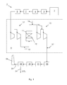
- Further characteristics and advantages will be more apparent from the description of a preferred but non-exclusive embodiment of the method and system, illustrated by way of non-limiting example in the accompanying drawing, in which:
-
Figure 1 shows an example of a system that implements the method of the invention. - In the following, the system for removing NOx from flue gas by SCR is described first.
- A
boiler 1 combusts a fuel such as coal with an oxidizer, such as air or oxygen or oxygen enriched air, and generates flue gas that is forwarded to a fluegas treatment system 2. - The flue
gas treatment system 2 can include adedusting unit 5 such as filters or electrostatic precipitators, amercury removal unit 6, asulphur removal unit 7 and acondenser 8 for water removal. The sequence in which these components are arranged is not relevant for the present invention and the presence of one or more of these components is also not relevant for the present invention. Thus the sequence of the components could be different and one or more of these components could not be present without affecting the present invention. Downstream of these components the fluegas treatment system 2 has asystem 9 for NOx removal. - The
system 9 for NOx removal comprises asupply 10 for a reagent into the flue gas, and areactor 11 including acatalyst 12 for SCR reaction downstream of thesupply 10. - The reagent can be one or a mixture of the reagents commonly used for SCR, such as for example ammonia or urea. Other reagents can anyhow be used. The catalyst is likewise a catalyst commonly used for SCR, and can for example include vanadium, molybdenum, tungsten, zeolites, etc.
- Downstream of the
reactor 11, thesystem 9 for NOx removal includes means for final NOx removal. - In a first example the means for final NOx removal includes a
compressor 15 like for example a multistage compressor able to compress the flue gas in a plurality of compression stages; in fact when considering the equilibrium
NO + ½ O2 ↔ NO2 [1]
the high pressure pushes the equilibrium to the right, such that NO is converted into NO2 that forms acidic solutions when liquid water is present. So NOx as such can easily be removed by cooling the gas below the dew point together with the forming water condensate. Alternately also a water injection could be done to achieve the same effect. - In a second example, the means for final NOx removal includes a
supply 16 for oxidizer. The oxidizer can be hydrogen peroxide H2O2, other oxidizers are anyhow possible. The oxidizer causes oxidation of NO into NO2 according to the reaction
NO + H2O2 → NO2 + H2O [2]
- NO2 is then removed with the water like in the first example.
- Different embodiments of the
system 9 for NOx removal can be provided with either thecompressor 15 or thesupply 16 for oxidizer or both thecompressor 15 and thesupply 16 for oxidizer. Adding of oxidizer in addition to increasing the pressure allows to speed up the reaction and reduce the residence time. When both thecompressor 15 and thesupply 16 for oxidizer are provided, the supply foroxidizer 16 can be located upstream of the compressor or between two compression stages. Naturally also more than onesupply 16 can be provided, upstream and/or between two compression stages. - In addition, according to a preferred embodiment of the
system 9 for NOx removal, acompressor 17 is also provided upstream of thereactor 11; thecompressor 17 can be for example a multistage compressor able to compress the flue gas in a plurality of compression stages. Thiscompressor 17 allows operation of the SCR at relatively high pressure. High pressure allows to minimize the SCR equipment size. Furthermore advantageously the flue gas at that location already has a low content of sulphur and particulate thus extending the lifetime of the catalyst. - Downstream of the
reactor 11 and, when provided, either of thecompressor 12, theperoxide injection 16 or both, the equilibrium of the reaction [1] above is pushed to the right such that NO conversion into NO2 is enhanced and NOx removal is more efficient. - Downstream of the reactor the flue
gas treatment system 2 may include further process steps like amercury removal unit 20, a water separator 21 and conditionally also adryer 22 and a CO2 separator 23. From the CO2 separator 23 aline 24 forwards CO2 to further treatments or sequestration, and a line 25 forwards the flue gas deprived from CO2 to thestack 26. Also in this case, the sequence of the components could be different and one or more of these components could not be present without affecting the present invention. - The operation of the flue
gas treatment system 2 having the system for NOx removal 9 is apparent from what described and illustrated and is substantially the following. - The
boiler 1 generates flue gas by combusting a fuel such as coal with an oxidizer. The flue gas is cleaned by passing it through thededusting unit 5,mercury removal unit 6,sulphur removal unit 7 and its mass flow is reduced by passing it through thecondenser 8. - The flue gas is then compressed at the
compressor 17 to a pressure below 10 bar, for example between 5-8 bar. - Then a reagent is added to the flue gas via the
supply 10. The reagent could be for example ammonia NH3. Ammonia reacts with NO and NO2 for example according to the reactions
4NO + 4NH3 → 4N2 + 6H2O [3]
2NO2 + 4NH3 → 3N2 + 6H2O [4]
2NO + 2NO2 + 4NH3 → 4N2 + 6H2O. [5]
- The conversion of NO and NO2 into N2 and water in the
reactor 11 is not complete because of the less than stoichiometric amount of reagent added to the flue gas. The conversion is anyhow such that the final conversion is economically feasible. Downstream of thereactor 11, the oxidizer such as hydrogen peroxide H2O2 is added into the flue gas through thesupply 16. - The oxidizer causes further conversion of NO into NO2 according to the reaction
NO + H2O2 → NO2 + H2O [6]
such that the flue gas downstream of the supply foroxidizer 16 is practically free of NO, the whole NO having being converted into NO2. - In addition, the flue gas is further compressed at the
compressors 15 to a pressure of more than for example 10 bar. This pushes the equilibrium [1] to the right, increasing the amount of NO2 in the flue gas and in parallel decreasing the amount of NO in the flue gas and thus enhancing the conversion of NO into NO2. - NO2 reacts with water (for example the water coming out of the reactions above or additional water supplied via a
supply 27 for water) according to the reaction
3 NO2 + H2O → 2 HNO3 + NO [7]
that is soluble in water and can easily be removed with water. - The flue gas is thus further treated at the
mercury removal unit 20, water separator 21 anddryer 22. At the water separator 21 water is removed and together with the water also the HNO3 generated according to the reaction [7] is removed. - Thus flue gas free of water and other contaminants like NOx is forwarded from the water separator 21 via the
dryer 22 to the CO2 separator 23. At the CO2 separator 23 CO2 is separated and collected via theline 24, while the flue gas deprived of CO2 and contaminants is sent to the atmosphere via thestack 26. - The present invention also refers to a method for removing NOx from flue gas by SCR.
- The method comprises supplying a reagent for the SCR reaction of NOx into the flue gas, and then contacting the flue gas with a catalyst.
- Advantageously, supplying the reagent includes supplying a less than stoichiometric amount of reagent, and after contacting the flue gas with a catalyst a final NOx removal step is provided.
- The less than stoichiometric amount of reagent is arranged to remove at least 80%, more preferably between 80-95% and more preferably between 85-90% of NOx by volume from the flue gas.
- In addition, preferably the flue gas is compressed before contacting the flue gas with the catalyst.
- The stoichiometric and/or less than stoichiometric amount of reagent can be determined on the basis of measured or calculated NOx content of the flue gas.
- The final NOx removal step comprises compressing the flue gas in at least one compression stage and/or supplying an oxidizer into the flue gas after contacting the flue gas with a catalyst. When both compression and supply of oxidizer are provided as the final NOx removal step, the supply of oxidizer can be carried out upstream and/or between the compression stages. In addition, the flue gas is preferably cooled between each compression stage.
- Naturally the features described may be independently provided from one another.
- In practice the materials used and the dimensions can be chosen at will according to requirements and to the state of the art.
-
- 1
- boiler
- 2
- flue gas treatment system
- 5
- dedusting unit
- 6
- mercury removal unit
- 7
- sulfur removal unit
- 8
- condenser
- 9
- system for NOx removal
- 10
- supply for reagent
- 11
- reactor
- 12
- catalyst
- 15
- compressor
- 16
- supply for oxidizer
- 17
- compressor
- 20
- mercury removal unit
- 21
- water separator
- 22
- dryer
- 23
- CO2 separator
- 24
- line
- 25
- line
- 26
- stack
- 27
- supply for water
Claims (15)
- A method for removing NOx from flue gas by SCR, comprising
supplying a reagent for the SCR reaction of NOx into the flue gas, then
contacting the flue gas with a catalyst (12), characterised in that
supplying the reagent includes supplying a less than stoichiometric amount of reagent,
and in that after contacting the flue gas with a catalyst (12) a final NOx removal step is provided. - The method of claim 1, characterized in that the less than stoichiometric amount of reagent is arranged to remove at least 80%, more preferably between 80-95% and more preferably between 85-90% of NOx by volume from the flue gas.
- The method of claim 1, characterized in that the final NOx removal step comprises compressing the flue gas.
- The method of claim 3, characterized in that compressing the flue gas comprises compressing the flue gas in a plurality of compression stages.
- The method of claim 1, characterized in that the final NOx removal step comprises supplying an oxidizer into the flue gas after contacting the flue gas with a catalyst (12).
- The method of claims 3 and 5 or 4 and 5, characterized by supplying the oxidizer before compressing.
- The method of claims 4 and 5, characterized by supplying the oxidizer between two compression stages.
- The method of claim 6 or 7, characterized by cooling the flue gas after compressing or after each compression stage.
- The method of claim 1, characterized by compressing the flue gas before contacting the flue gas with a catalyst (12).
- The method of claim 1, characterized by determining the stoichiometric and/or less than stoichiometric amount of reagent on the basis of measured or calculated NOx content of the flue gas.
- A system (9) for removing NOx from flue gas by SCR, comprising
a supply (10) for a reagent into the flue gas,
a reactor (11) including a catalyst (12) for SCR reaction downstream of the supply (10) for reagent, characterised by further comprising
means (15, 16) for final NOx removal downstream of the reactor (11). - The system (9) of claim 11, characterized in that the the means (15, 16) for final NOx removal includes a compressor (15).
- The system (9) of claim 11, characterized in that the the means (15, 16) for final NOx removal includes a supply (16) for oxidizer.
- The system (9) of claim 11, characterized by further comprising a compressor (17) upstream of the reactor (11).
- The system (9) of claim 11, characterized by further comprising a supply (27) for water downstream of the reactor (11).
Priority Applications (5)
| Application Number | Priority Date | Filing Date | Title |
|---|---|---|---|
| EP14181291.7A EP2987550B1 (en) | 2014-08-18 | 2014-08-18 | Method for nox removal |
| US14/813,630 US10821400B2 (en) | 2014-08-18 | 2015-07-30 | Method and system for NOx removal |
| AU2015210359A AU2015210359A1 (en) | 2014-08-18 | 2015-08-05 | Method and system for NOx removal |
| CA2899921A CA2899921A1 (en) | 2014-08-18 | 2015-08-10 | Method and system for nox removal |
| CN201510506448.5A CN105363345A (en) | 2014-08-18 | 2015-08-18 | METHOD AND SYSTEM FOR NOx REMOVAL |
Applications Claiming Priority (1)
| Application Number | Priority Date | Filing Date | Title |
|---|---|---|---|
| EP14181291.7A EP2987550B1 (en) | 2014-08-18 | 2014-08-18 | Method for nox removal |
Publications (2)
| Publication Number | Publication Date |
|---|---|
| EP2987550A1 true EP2987550A1 (en) | 2016-02-24 |
| EP2987550B1 EP2987550B1 (en) | 2019-03-20 |
Family
ID=51352464
Family Applications (1)
| Application Number | Title | Priority Date | Filing Date |
|---|---|---|---|
| EP14181291.7A Active EP2987550B1 (en) | 2014-08-18 | 2014-08-18 | Method for nox removal |
Country Status (5)
| Country | Link |
|---|---|
| US (1) | US10821400B2 (en) |
| EP (1) | EP2987550B1 (en) |
| CN (1) | CN105363345A (en) |
| AU (1) | AU2015210359A1 (en) |
| CA (1) | CA2899921A1 (en) |
Families Citing this family (2)
| Publication number | Priority date | Publication date | Assignee | Title |
|---|---|---|---|---|
| CN110559826A (en) * | 2019-08-02 | 2019-12-13 | 华中科技大学 | An oxidation absorption equipment for the integrated removal of multiple pollutants in coal-fired flue gas |
| TW202442296A (en) * | 2023-03-29 | 2024-11-01 | 美商美國農業能源公司 | Systems and methods for obtaining nitrogen and carbon dioxide from a flue gas |
Citations (6)
| Publication number | Priority date | Publication date | Assignee | Title |
|---|---|---|---|---|
| CA2299701A1 (en) * | 1995-08-23 | 1997-02-24 | The Boc Group, Inc. | Process for the production of high purity carbon dioxide |
| WO2006025900A2 (en) * | 2004-08-27 | 2006-03-09 | Cichanowicz J Edward | Multi-stage heat absorbing reactor and process for scr of nox and for oxidation of elemental mercury |
| DE102008062495A1 (en) | 2008-12-16 | 2010-06-17 | Linde-Kca-Dresden Gmbh | Process and apparatus for catalytic denitrification of gas streams from large combustion plant |
| DE102008062496A1 (en) | 2008-12-16 | 2010-06-17 | Linde-Kca-Dresden Gmbh | Process for the removal of impurities from oxygen-containing gas streams |
| US20100290965A1 (en) * | 2009-05-15 | 2010-11-18 | Fmc Corporation | COMBUSTION FLUE GAS NOx TREATMENT |
| EP2481471A1 (en) * | 2011-02-01 | 2012-08-01 | Alstom Technology Ltd | Apparatus and system for NOx reduction in wet flue gas |
Family Cites Families (2)
| Publication number | Priority date | Publication date | Assignee | Title |
|---|---|---|---|---|
| US4781902A (en) * | 1986-10-29 | 1988-11-01 | Haldor Topsoe A/S | Process for the removal of nitrogen oxides and sulphur oxides from flue gases |
| US8323602B2 (en) * | 2010-07-08 | 2012-12-04 | Air Products And Chemicals, Inc. | Treatment of flue gas from an oxyfuel combustion process |
-
2014
- 2014-08-18 EP EP14181291.7A patent/EP2987550B1/en active Active
-
2015
- 2015-07-30 US US14/813,630 patent/US10821400B2/en active Active
- 2015-08-05 AU AU2015210359A patent/AU2015210359A1/en not_active Abandoned
- 2015-08-10 CA CA2899921A patent/CA2899921A1/en not_active Abandoned
- 2015-08-18 CN CN201510506448.5A patent/CN105363345A/en active Pending
Patent Citations (6)
| Publication number | Priority date | Publication date | Assignee | Title |
|---|---|---|---|---|
| CA2299701A1 (en) * | 1995-08-23 | 1997-02-24 | The Boc Group, Inc. | Process for the production of high purity carbon dioxide |
| WO2006025900A2 (en) * | 2004-08-27 | 2006-03-09 | Cichanowicz J Edward | Multi-stage heat absorbing reactor and process for scr of nox and for oxidation of elemental mercury |
| DE102008062495A1 (en) | 2008-12-16 | 2010-06-17 | Linde-Kca-Dresden Gmbh | Process and apparatus for catalytic denitrification of gas streams from large combustion plant |
| DE102008062496A1 (en) | 2008-12-16 | 2010-06-17 | Linde-Kca-Dresden Gmbh | Process for the removal of impurities from oxygen-containing gas streams |
| US20100290965A1 (en) * | 2009-05-15 | 2010-11-18 | Fmc Corporation | COMBUSTION FLUE GAS NOx TREATMENT |
| EP2481471A1 (en) * | 2011-02-01 | 2012-08-01 | Alstom Technology Ltd | Apparatus and system for NOx reduction in wet flue gas |
Also Published As
| Publication number | Publication date |
|---|---|
| US10821400B2 (en) | 2020-11-03 |
| EP2987550B1 (en) | 2019-03-20 |
| CN105363345A (en) | 2016-03-02 |
| CA2899921A1 (en) | 2016-02-18 |
| US20160045864A1 (en) | 2016-02-18 |
| AU2015210359A1 (en) | 2016-03-03 |
Similar Documents
| Publication | Publication Date | Title |
|---|---|---|
| CA2743713C (en) | Process for removing impurities from oxygen-containing gas streams | |
| EP2404655B1 (en) | Removal of SOx from compressed oxyfuel-derived CO2 | |
| US8282901B2 (en) | Integration of catalytic CO2 oxidation and oxyfuel sour compression | |
| EP4371650B1 (en) | Prevention of nitro-amine formation in carbon dioxide absorption processes | |
| EP2404660B1 (en) | Sorbent use with oxyfuel sour compression | |
| EP2987550B1 (en) | Method for nox removal | |
| EP2939727A1 (en) | Apparatus and method for integrating desulfurization and carbon dioxide capture | |
| CN205032068U (en) | Buggy oxygen boosting burning flue gas demercuration system | |
| CN104971596A (en) | Demercuration system and method for pulverized coal oxygen-enriched combustion smoke | |
| CN105561747A (en) | Combined removal process for flue gas in coal-fired boiler | |
| WO2013144833A1 (en) | Method and apparatus for nox removal from co2 rich flue stream | |
| CN113117491A (en) | Desulfurization and denitrification process based on calcium-based absorbent |
Legal Events
| Date | Code | Title | Description |
|---|---|---|---|
| PUAI | Public reference made under article 153(3) epc to a published international application that has entered the european phase |
Free format text: ORIGINAL CODE: 0009012 |
|
| AK | Designated contracting states |
Kind code of ref document: A1 Designated state(s): AL AT BE BG CH CY CZ DE DK EE ES FI FR GB GR HR HU IE IS IT LI LT LU LV MC MK MT NL NO PL PT RO RS SE SI SK SM TR |
|
| AX | Request for extension of the european patent |
Extension state: BA ME |
|
| RAP1 | Party data changed (applicant data changed or rights of an application transferred) |
Owner name: GENERAL ELECTRIC TECHNOLOGY GMBH |
|
| 17P | Request for examination filed |
Effective date: 20160824 |
|
| RBV | Designated contracting states (corrected) |
Designated state(s): AL AT BE BG CH CY CZ DE DK EE ES FI FR GB GR HR HU IE IS IT LI LT LU LV MC MK MT NL NO PL PT RO RS SE SI SK SM TR |
|
| GRAP | Despatch of communication of intention to grant a patent |
Free format text: ORIGINAL CODE: EPIDOSNIGR1 |
|
| STAA | Information on the status of an ep patent application or granted ep patent |
Free format text: STATUS: GRANT OF PATENT IS INTENDED |
|
| RIC1 | Information provided on ipc code assigned before grant |
Ipc: B01D 53/86 20060101ALI20180913BHEP Ipc: B01D 53/78 20060101ALI20180913BHEP Ipc: B01D 53/56 20060101AFI20180913BHEP Ipc: B01D 53/75 20060101ALI20180913BHEP |
|
| INTG | Intention to grant announced |
Effective date: 20181017 |
|
| GRAS | Grant fee paid |
Free format text: ORIGINAL CODE: EPIDOSNIGR3 |
|
| GRAA | (expected) grant |
Free format text: ORIGINAL CODE: 0009210 |
|
| STAA | Information on the status of an ep patent application or granted ep patent |
Free format text: STATUS: THE PATENT HAS BEEN GRANTED |
|
| AK | Designated contracting states |
Kind code of ref document: B1 Designated state(s): AL AT BE BG CH CY CZ DE DK EE ES FI FR GB GR HR HU IE IS IT LI LT LU LV MC MK MT NL NO PL PT RO RS SE SI SK SM TR |
|
| REG | Reference to a national code |
Ref country code: GB Ref legal event code: FG4D |
|
| REG | Reference to a national code |
Ref country code: CH Ref legal event code: EP |
|
| REG | Reference to a national code |
Ref country code: DE Ref legal event code: R096 Ref document number: 602014043162 Country of ref document: DE |
|
| REG | Reference to a national code |
Ref country code: AT Ref legal event code: REF Ref document number: 1109953 Country of ref document: AT Kind code of ref document: T Effective date: 20190415 |
|
| REG | Reference to a national code |
Ref country code: IE Ref legal event code: FG4D |
|
| REG | Reference to a national code |
Ref country code: NL Ref legal event code: MP Effective date: 20190320 |
|
| PG25 | Lapsed in a contracting state [announced via postgrant information from national office to epo] |
Ref country code: SE Free format text: LAPSE BECAUSE OF FAILURE TO SUBMIT A TRANSLATION OF THE DESCRIPTION OR TO PAY THE FEE WITHIN THE PRESCRIBED TIME-LIMIT Effective date: 20190320 Ref country code: LT Free format text: LAPSE BECAUSE OF FAILURE TO SUBMIT A TRANSLATION OF THE DESCRIPTION OR TO PAY THE FEE WITHIN THE PRESCRIBED TIME-LIMIT Effective date: 20190320 Ref country code: FI Free format text: LAPSE BECAUSE OF FAILURE TO SUBMIT A TRANSLATION OF THE DESCRIPTION OR TO PAY THE FEE WITHIN THE PRESCRIBED TIME-LIMIT Effective date: 20190320 Ref country code: NO Free format text: LAPSE BECAUSE OF FAILURE TO SUBMIT A TRANSLATION OF THE DESCRIPTION OR TO PAY THE FEE WITHIN THE PRESCRIBED TIME-LIMIT Effective date: 20190620 |
|
| REG | Reference to a national code |
Ref country code: LT Ref legal event code: MG4D |
|
| PG25 | Lapsed in a contracting state [announced via postgrant information from national office to epo] |
Ref country code: GR Free format text: LAPSE BECAUSE OF FAILURE TO SUBMIT A TRANSLATION OF THE DESCRIPTION OR TO PAY THE FEE WITHIN THE PRESCRIBED TIME-LIMIT Effective date: 20190621 Ref country code: BG Free format text: LAPSE BECAUSE OF FAILURE TO SUBMIT A TRANSLATION OF THE DESCRIPTION OR TO PAY THE FEE WITHIN THE PRESCRIBED TIME-LIMIT Effective date: 20190620 Ref country code: HR Free format text: LAPSE BECAUSE OF FAILURE TO SUBMIT A TRANSLATION OF THE DESCRIPTION OR TO PAY THE FEE WITHIN THE PRESCRIBED TIME-LIMIT Effective date: 20190320 Ref country code: LV Free format text: LAPSE BECAUSE OF FAILURE TO SUBMIT A TRANSLATION OF THE DESCRIPTION OR TO PAY THE FEE WITHIN THE PRESCRIBED TIME-LIMIT Effective date: 20190320 Ref country code: NL Free format text: LAPSE BECAUSE OF FAILURE TO SUBMIT A TRANSLATION OF THE DESCRIPTION OR TO PAY THE FEE WITHIN THE PRESCRIBED TIME-LIMIT Effective date: 20190320 Ref country code: RS Free format text: LAPSE BECAUSE OF FAILURE TO SUBMIT A TRANSLATION OF THE DESCRIPTION OR TO PAY THE FEE WITHIN THE PRESCRIBED TIME-LIMIT Effective date: 20190320 |
|
| REG | Reference to a national code |
Ref country code: AT Ref legal event code: MK05 Ref document number: 1109953 Country of ref document: AT Kind code of ref document: T Effective date: 20190320 |
|
| PG25 | Lapsed in a contracting state [announced via postgrant information from national office to epo] |
Ref country code: SK Free format text: LAPSE BECAUSE OF FAILURE TO SUBMIT A TRANSLATION OF THE DESCRIPTION OR TO PAY THE FEE WITHIN THE PRESCRIBED TIME-LIMIT Effective date: 20190320 Ref country code: IT Free format text: LAPSE BECAUSE OF FAILURE TO SUBMIT A TRANSLATION OF THE DESCRIPTION OR TO PAY THE FEE WITHIN THE PRESCRIBED TIME-LIMIT Effective date: 20190320 Ref country code: EE Free format text: LAPSE BECAUSE OF FAILURE TO SUBMIT A TRANSLATION OF THE DESCRIPTION OR TO PAY THE FEE WITHIN THE PRESCRIBED TIME-LIMIT Effective date: 20190320 Ref country code: CZ Free format text: LAPSE BECAUSE OF FAILURE TO SUBMIT A TRANSLATION OF THE DESCRIPTION OR TO PAY THE FEE WITHIN THE PRESCRIBED TIME-LIMIT Effective date: 20190320 Ref country code: RO Free format text: LAPSE BECAUSE OF FAILURE TO SUBMIT A TRANSLATION OF THE DESCRIPTION OR TO PAY THE FEE WITHIN THE PRESCRIBED TIME-LIMIT Effective date: 20190320 Ref country code: ES Free format text: LAPSE BECAUSE OF FAILURE TO SUBMIT A TRANSLATION OF THE DESCRIPTION OR TO PAY THE FEE WITHIN THE PRESCRIBED TIME-LIMIT Effective date: 20190320 Ref country code: AL Free format text: LAPSE BECAUSE OF FAILURE TO SUBMIT A TRANSLATION OF THE DESCRIPTION OR TO PAY THE FEE WITHIN THE PRESCRIBED TIME-LIMIT Effective date: 20190320 Ref country code: PT Free format text: LAPSE BECAUSE OF FAILURE TO SUBMIT A TRANSLATION OF THE DESCRIPTION OR TO PAY THE FEE WITHIN THE PRESCRIBED TIME-LIMIT Effective date: 20190720 |
|
| PG25 | Lapsed in a contracting state [announced via postgrant information from national office to epo] |
Ref country code: PL Free format text: LAPSE BECAUSE OF FAILURE TO SUBMIT A TRANSLATION OF THE DESCRIPTION OR TO PAY THE FEE WITHIN THE PRESCRIBED TIME-LIMIT Effective date: 20190320 Ref country code: SM Free format text: LAPSE BECAUSE OF FAILURE TO SUBMIT A TRANSLATION OF THE DESCRIPTION OR TO PAY THE FEE WITHIN THE PRESCRIBED TIME-LIMIT Effective date: 20190320 |
|
| PG25 | Lapsed in a contracting state [announced via postgrant information from national office to epo] |
Ref country code: AT Free format text: LAPSE BECAUSE OF FAILURE TO SUBMIT A TRANSLATION OF THE DESCRIPTION OR TO PAY THE FEE WITHIN THE PRESCRIBED TIME-LIMIT Effective date: 20190320 Ref country code: IS Free format text: LAPSE BECAUSE OF FAILURE TO SUBMIT A TRANSLATION OF THE DESCRIPTION OR TO PAY THE FEE WITHIN THE PRESCRIBED TIME-LIMIT Effective date: 20190720 |
|
| REG | Reference to a national code |
Ref country code: DE Ref legal event code: R097 Ref document number: 602014043162 Country of ref document: DE |
|
| PLBE | No opposition filed within time limit |
Free format text: ORIGINAL CODE: 0009261 |
|
| STAA | Information on the status of an ep patent application or granted ep patent |
Free format text: STATUS: NO OPPOSITION FILED WITHIN TIME LIMIT |
|
| PG25 | Lapsed in a contracting state [announced via postgrant information from national office to epo] |
Ref country code: DK Free format text: LAPSE BECAUSE OF FAILURE TO SUBMIT A TRANSLATION OF THE DESCRIPTION OR TO PAY THE FEE WITHIN THE PRESCRIBED TIME-LIMIT Effective date: 20190320 |
|
| 26N | No opposition filed |
Effective date: 20200102 |
|
| PG25 | Lapsed in a contracting state [announced via postgrant information from national office to epo] |
Ref country code: SI Free format text: LAPSE BECAUSE OF FAILURE TO SUBMIT A TRANSLATION OF THE DESCRIPTION OR TO PAY THE FEE WITHIN THE PRESCRIBED TIME-LIMIT Effective date: 20190320 |
|
| PG25 | Lapsed in a contracting state [announced via postgrant information from national office to epo] |
Ref country code: TR Free format text: LAPSE BECAUSE OF FAILURE TO SUBMIT A TRANSLATION OF THE DESCRIPTION OR TO PAY THE FEE WITHIN THE PRESCRIBED TIME-LIMIT Effective date: 20190320 |
|
| GBPC | Gb: european patent ceased through non-payment of renewal fee |
Effective date: 20190818 |
|
| PG25 | Lapsed in a contracting state [announced via postgrant information from national office to epo] |
Ref country code: LU Free format text: LAPSE BECAUSE OF NON-PAYMENT OF DUE FEES Effective date: 20190818 Ref country code: CH Free format text: LAPSE BECAUSE OF NON-PAYMENT OF DUE FEES Effective date: 20190831 Ref country code: MC Free format text: LAPSE BECAUSE OF FAILURE TO SUBMIT A TRANSLATION OF THE DESCRIPTION OR TO PAY THE FEE WITHIN THE PRESCRIBED TIME-LIMIT Effective date: 20190320 Ref country code: LI Free format text: LAPSE BECAUSE OF NON-PAYMENT OF DUE FEES Effective date: 20190831 |
|
| REG | Reference to a national code |
Ref country code: BE Ref legal event code: MM Effective date: 20190831 |
|
| PG25 | Lapsed in a contracting state [announced via postgrant information from national office to epo] |
Ref country code: IE Free format text: LAPSE BECAUSE OF NON-PAYMENT OF DUE FEES Effective date: 20190818 Ref country code: FR Free format text: LAPSE BECAUSE OF NON-PAYMENT OF DUE FEES Effective date: 20190831 |
|
| PG25 | Lapsed in a contracting state [announced via postgrant information from national office to epo] |
Ref country code: BE Free format text: LAPSE BECAUSE OF NON-PAYMENT OF DUE FEES Effective date: 20190831 Ref country code: GB Free format text: LAPSE BECAUSE OF NON-PAYMENT OF DUE FEES Effective date: 20190818 |
|
| PG25 | Lapsed in a contracting state [announced via postgrant information from national office to epo] |
Ref country code: CY Free format text: LAPSE BECAUSE OF FAILURE TO SUBMIT A TRANSLATION OF THE DESCRIPTION OR TO PAY THE FEE WITHIN THE PRESCRIBED TIME-LIMIT Effective date: 20190320 |
|
| PG25 | Lapsed in a contracting state [announced via postgrant information from national office to epo] |
Ref country code: MT Free format text: LAPSE BECAUSE OF FAILURE TO SUBMIT A TRANSLATION OF THE DESCRIPTION OR TO PAY THE FEE WITHIN THE PRESCRIBED TIME-LIMIT Effective date: 20190320 Ref country code: HU Free format text: LAPSE BECAUSE OF FAILURE TO SUBMIT A TRANSLATION OF THE DESCRIPTION OR TO PAY THE FEE WITHIN THE PRESCRIBED TIME-LIMIT; INVALID AB INITIO Effective date: 20140818 |
|
| PG25 | Lapsed in a contracting state [announced via postgrant information from national office to epo] |
Ref country code: MK Free format text: LAPSE BECAUSE OF FAILURE TO SUBMIT A TRANSLATION OF THE DESCRIPTION OR TO PAY THE FEE WITHIN THE PRESCRIBED TIME-LIMIT Effective date: 20190320 |
|
| PGFP | Annual fee paid to national office [announced via postgrant information from national office to epo] |
Ref country code: DE Payment date: 20250724 Year of fee payment: 12 |